EP2812574B1 - Systeme und verfahren zur überwachung von durch ein scheibenpumpsystem abgegebenem reduziertem druck - Google Patents
Systeme und verfahren zur überwachung von durch ein scheibenpumpsystem abgegebenem reduziertem druck Download PDFInfo
- Publication number
- EP2812574B1 EP2812574B1 EP13705084.5A EP13705084A EP2812574B1 EP 2812574 B1 EP2812574 B1 EP 2812574B1 EP 13705084 A EP13705084 A EP 13705084A EP 2812574 B1 EP2812574 B1 EP 2812574B1
- Authority
- EP
- European Patent Office
- Prior art keywords
- end wall
- disc pump
- driven end
- pressure
- actuator
- Prior art date
- Legal status (The legal status is an assumption and is not a legal conclusion. Google has not performed a legal analysis and makes no representation as to the accuracy of the status listed.)
- Active
Links
- 238000000034 method Methods 0.000 title claims description 13
- 230000002829 reductive effect Effects 0.000 title description 12
- 238000012544 monitoring process Methods 0.000 title 1
- 238000006073 displacement reaction Methods 0.000 claims description 86
- 230000010355 oscillation Effects 0.000 claims description 77
- 239000012530 fluid Substances 0.000 claims description 68
- 239000000463 material Substances 0.000 claims description 34
- 230000033001 locomotion Effects 0.000 claims description 22
- 230000002093 peripheral effect Effects 0.000 claims description 20
- 230000004044 response Effects 0.000 claims description 18
- 230000008859 change Effects 0.000 claims description 16
- 230000003534 oscillatory effect Effects 0.000 claims description 13
- 238000007789 sealing Methods 0.000 description 33
- 230000014759 maintenance of location Effects 0.000 description 28
- 230000006870 function Effects 0.000 description 16
- 238000005452 bending Methods 0.000 description 9
- 230000007423 decrease Effects 0.000 description 7
- 239000000758 substrate Substances 0.000 description 7
- 239000002184 metal Substances 0.000 description 6
- 229910052751 metal Inorganic materials 0.000 description 6
- 238000004891 communication Methods 0.000 description 5
- 230000001276 controlling effect Effects 0.000 description 5
- 230000001965 increasing effect Effects 0.000 description 5
- 238000005086 pumping Methods 0.000 description 5
- 239000000919 ceramic Substances 0.000 description 4
- 238000012545 processing Methods 0.000 description 4
- 230000009467 reduction Effects 0.000 description 4
- 230000009471 action Effects 0.000 description 3
- 230000000694 effects Effects 0.000 description 3
- 230000000670 limiting effect Effects 0.000 description 3
- 229920000728 polyester Polymers 0.000 description 3
- -1 polyethylene Polymers 0.000 description 3
- 239000007787 solid Substances 0.000 description 3
- 230000003068 static effect Effects 0.000 description 3
- RYGMFSIKBFXOCR-UHFFFAOYSA-N Copper Chemical compound [Cu] RYGMFSIKBFXOCR-UHFFFAOYSA-N 0.000 description 2
- 239000004697 Polyetherimide Substances 0.000 description 2
- 239000004642 Polyimide Substances 0.000 description 2
- 239000000853 adhesive Substances 0.000 description 2
- 230000001070 adhesive effect Effects 0.000 description 2
- 230000008901 benefit Effects 0.000 description 2
- 238000003486 chemical etching Methods 0.000 description 2
- 238000013016 damping Methods 0.000 description 2
- 230000001419 dependent effect Effects 0.000 description 2
- 238000013461 design Methods 0.000 description 2
- 238000010586 diagram Methods 0.000 description 2
- 239000011521 glass Substances 0.000 description 2
- 230000007246 mechanism Effects 0.000 description 2
- 229920001601 polyetherimide Polymers 0.000 description 2
- 229920001721 polyimide Polymers 0.000 description 2
- 229920000642 polymer Polymers 0.000 description 2
- 230000008569 process Effects 0.000 description 2
- 230000001105 regulatory effect Effects 0.000 description 2
- 238000003860 storage Methods 0.000 description 2
- 229920000106 Liquid crystal polymer Polymers 0.000 description 1
- 239000004977 Liquid-crystal polymers (LCPs) Substances 0.000 description 1
- 239000004698 Polyethylene Substances 0.000 description 1
- 229910000831 Steel Inorganic materials 0.000 description 1
- 239000011149 active material Substances 0.000 description 1
- 230000003190 augmentative effect Effects 0.000 description 1
- 238000005422 blasting Methods 0.000 description 1
- 238000009530 blood pressure measurement Methods 0.000 description 1
- 230000008602 contraction Effects 0.000 description 1
- 229910052802 copper Inorganic materials 0.000 description 1
- 239000010949 copper Substances 0.000 description 1
- 239000011889 copper foil Substances 0.000 description 1
- 230000003247 decreasing effect Effects 0.000 description 1
- 230000007547 defect Effects 0.000 description 1
- 230000032798 delamination Effects 0.000 description 1
- 238000011161 development Methods 0.000 description 1
- 230000018109 developmental process Effects 0.000 description 1
- 230000003467 diminishing effect Effects 0.000 description 1
- 238000009826 distribution Methods 0.000 description 1
- 238000005553 drilling Methods 0.000 description 1
- 238000004070 electrodeposition Methods 0.000 description 1
- 230000002708 enhancing effect Effects 0.000 description 1
- 229920005570 flexible polymer Polymers 0.000 description 1
- 239000011888 foil Substances 0.000 description 1
- 230000001939 inductive effect Effects 0.000 description 1
- 230000002452 interceptive effect Effects 0.000 description 1
- 239000003562 lightweight material Substances 0.000 description 1
- 239000007788 liquid Substances 0.000 description 1
- 238000003754 machining Methods 0.000 description 1
- 238000004519 manufacturing process Methods 0.000 description 1
- 239000012528 membrane Substances 0.000 description 1
- 230000000116 mitigating effect Effects 0.000 description 1
- 238000012986 modification Methods 0.000 description 1
- 230000004048 modification Effects 0.000 description 1
- 239000002991 molded plastic Substances 0.000 description 1
- 230000036961 partial effect Effects 0.000 description 1
- 230000021715 photosynthesis, light harvesting Effects 0.000 description 1
- 239000004033 plastic Substances 0.000 description 1
- 229920003023 plastic Polymers 0.000 description 1
- 229920000573 polyethylene Polymers 0.000 description 1
- 229920000139 polyethylene terephthalate Polymers 0.000 description 1
- 239000005020 polyethylene terephthalate Substances 0.000 description 1
- 229920006254 polymer film Polymers 0.000 description 1
- 239000000843 powder Substances 0.000 description 1
- 239000012858 resilient material Substances 0.000 description 1
- 238000005096 rolling process Methods 0.000 description 1
- 238000005070 sampling Methods 0.000 description 1
- 239000010703 silicon Substances 0.000 description 1
- 229910052710 silicon Inorganic materials 0.000 description 1
- 239000010959 steel Substances 0.000 description 1
- 239000000126 substance Substances 0.000 description 1
- 230000001502 supplementing effect Effects 0.000 description 1
- 230000002195 synergetic effect Effects 0.000 description 1
- 230000007704 transition Effects 0.000 description 1
Images


Classifications
-
- F—MECHANICAL ENGINEERING; LIGHTING; HEATING; WEAPONS; BLASTING
- F04—POSITIVE - DISPLACEMENT MACHINES FOR LIQUIDS; PUMPS FOR LIQUIDS OR ELASTIC FLUIDS
- F04B—POSITIVE-DISPLACEMENT MACHINES FOR LIQUIDS; PUMPS
- F04B51/00—Testing machines, pumps, or pumping installations
-
- F—MECHANICAL ENGINEERING; LIGHTING; HEATING; WEAPONS; BLASTING
- F04—POSITIVE - DISPLACEMENT MACHINES FOR LIQUIDS; PUMPS FOR LIQUIDS OR ELASTIC FLUIDS
- F04B—POSITIVE-DISPLACEMENT MACHINES FOR LIQUIDS; PUMPS
- F04B43/00—Machines, pumps, or pumping installations having flexible working members
- F04B43/02—Machines, pumps, or pumping installations having flexible working members having plate-like flexible members, e.g. diaphragms
- F04B43/04—Pumps having electric drive
- F04B43/043—Micropumps
- F04B43/046—Micropumps with piezoelectric drive
-
- F—MECHANICAL ENGINEERING; LIGHTING; HEATING; WEAPONS; BLASTING
- F04—POSITIVE - DISPLACEMENT MACHINES FOR LIQUIDS; PUMPS FOR LIQUIDS OR ELASTIC FLUIDS
- F04B—POSITIVE-DISPLACEMENT MACHINES FOR LIQUIDS; PUMPS
- F04B43/00—Machines, pumps, or pumping installations having flexible working members
- F04B43/08—Machines, pumps, or pumping installations having flexible working members having tubular flexible members
- F04B43/09—Pumps having electric drive
- F04B43/095—Piezo-electric drive
-
- F—MECHANICAL ENGINEERING; LIGHTING; HEATING; WEAPONS; BLASTING
- F04—POSITIVE - DISPLACEMENT MACHINES FOR LIQUIDS; PUMPS FOR LIQUIDS OR ELASTIC FLUIDS
- F04F—PUMPING OF FLUID BY DIRECT CONTACT OF ANOTHER FLUID OR BY USING INERTIA OF FLUID TO BE PUMPED; SIPHONS
- F04F7/00—Pumps displacing fluids by using inertia thereof, e.g. by generating vibrations therein
-
- G—PHYSICS
- G01—MEASURING; TESTING
- G01L—MEASURING FORCE, STRESS, TORQUE, WORK, MECHANICAL POWER, MECHANICAL EFFICIENCY, OR FLUID PRESSURE
- G01L1/00—Measuring force or stress, in general
- G01L1/20—Measuring force or stress, in general by measuring variations in ohmic resistance of solid materials or of electrically-conductive fluids; by making use of electrokinetic cells, i.e. liquid-containing cells wherein an electrical potential is produced or varied upon the application of stress
- G01L1/22—Measuring force or stress, in general by measuring variations in ohmic resistance of solid materials or of electrically-conductive fluids; by making use of electrokinetic cells, i.e. liquid-containing cells wherein an electrical potential is produced or varied upon the application of stress using resistance strain gauges
-
- G—PHYSICS
- G01—MEASURING; TESTING
- G01L—MEASURING FORCE, STRESS, TORQUE, WORK, MECHANICAL POWER, MECHANICAL EFFICIENCY, OR FLUID PRESSURE
- G01L9/00—Measuring steady of quasi-steady pressure of fluid or fluent solid material by electric or magnetic pressure-sensitive elements; Transmitting or indicating the displacement of mechanical pressure-sensitive elements, used to measure the steady or quasi-steady pressure of a fluid or fluent solid material, by electric or magnetic means
- G01L9/0001—Transmitting or indicating the displacement of elastically deformable gauges by electric, electro-mechanical, magnetic or electro-magnetic means
- G01L9/0002—Transmitting or indicating the displacement of elastically deformable gauges by electric, electro-mechanical, magnetic or electro-magnetic means using variations in ohmic resistance
Definitions
- the illustrative embodiments of the invention relate generally to a disc pump for fluid and, more specifically, to a disc pump in which the pumping cavity is substantially cylindrically shaped having end walls and a side wall between the end walls with an actuator disposed between the end walls.
- the illustrative embodiments of the invention relate more specifically to a disc pump having a valve mounted in the actuator and at least one additional valve mounted in one of the end walls.
- thermo-acoustics The generation of high amplitude pressure oscillations in closed cavities has received significant attention in the fields of thermo-acoustics and disc pump type compressors. Recent developments in non-linear acoustics have allowed the generation of pressure waves with higher amplitudes than previously thought possible.
- acoustic resonance it is known to use acoustic resonance to achieve fluid pumping from defined inlets and outlets. This can be achieved using a cylindrical cavity with an acoustic driver at one end, which drives an acoustic standing wave. In such a cylindrical cavity, the acoustic pressure wave has limited amplitude. Varying cross-section cavities, such as cone, horn-cone, and bulb shapes have been used to achieve high amplitude pressure oscillations, thereby significantly increasing the pumping effect. In such high amplitude waves, the non-linear mechanisms with energy dissipation have been suppressed. However, high amplitude acoustic resonance has not been employed within disc-shaped cavities in which radial pressure oscillations are excited until recently.
- International Patent Application No. PCT/GB2006/001487 published as WO 2006/111775 , discloses a disc pump having a substantially disc-shaped cavity with a high aspect ratio, i.e., the ratio of the radius of the cavity to the height of the cavity
- Such a disc pump has a substantially cylindrical cavity comprising a side wall closed at each end by end walls.
- the disc pump also comprises an actuator that drives either one of the end walls to oscillate in a direction substantially perpendicular to the surface of the driven end wall.
- the spatial profile of the motion of the driven end wall is described as being matched to the spatial profile of the fluid pressure oscillations within the cavity, a state described herein as mode-matching.
- work done by the actuator on the fluid in the cavity adds constructively across the driven end wall surface, thereby enhancing the amplitude of the pressure oscillation in the cavity and delivering high disc pump efficiency.
- the efficiency of a mode-matched disc pump is dependent upon the interface between the driven end wall and the side wall. It is desirable to maintain the efficiency of such a disc pump by structuring the interface so that it does not decrease or dampen the motion of the driven end wall, thereby mitigating any reduction in the amplitude of the fluid pressure oscillations within the cavity.
- the actuator of the disc pump described above causes an oscillatory motion of the driven end wall ("displacement oscillations") in a direction substantially perpendicular to the end wall or substantially parallel to the longitudinal axis of the cylindrical cavity, referred to hereinafter as “axial oscillations" of the driven end wall within the cavity.
- the axial oscillations of the driven end wall generate substantially proportional "pressure oscillations" of fluid within the cavity creating a radial pressure distribution approximating that of a Bessel function of the first kind as described in International Patent Application No. PCT/GB2006/001487 , such oscillations referred to hereinafter as “radial oscillations" of the fluid pressure within the cavity.
- a portion of the driven end wall between the actuator and the side wall provides an interface with the side wall of the disc pump that decreases dampening of the displacement oscillations to mitigate any reduction of the pressure oscillations within the cavity.
- the portion of the driven end wall between the actuator and the sidewall is hereinafter referred to as an "isolator" and is described more specifically in U.S. Patent Application No. 12/477,594 .
- the illustrative embodiments of the isolator are operatively associated with the peripheral portion of the driven end wall to reduce dampening of the displacement oscillations.
- Such disc pumps also require one or more valves for controlling the flow of fluid through the disc pump and, more specifically, valves being capable of operating at high frequencies.
- Conventional valves typically operate at lower frequencies below 500 Hz for a variety of applications.
- many conventional compressors typically operate at 50 or 60 Hz.
- Linear resonance compressors that are known in the art operate between 150 and 350 Hz.
- many portable electronic devices, including medical devices require disc pumps for delivering a positive pressure or providing a vacuum that are relatively small in size, and it is advantageous for such disc pumps to be inaudible in operation so as to provide discrete operation. To achieve these objectives, such disc pumps must operate at very high frequencies, requiring valves capable of operating at about 20 kHz and higher.
- valve To operate at these high frequencies, the valve must be responsive to a high frequency oscillating pressure that can be rectified to create a net flow of fluid through the disc pump. Such a valve is described more specifically in International Patent Application No. PCT/GB2009/050614 .
- Valves may be disposed in either a first or a second aperture, or both apertures, for controlling the flow of fluid through the disc pump.
- Each valve comprises a first plate having apertures extending generally perpendicular therethrough and a second plate also having apertures extending generally perpendicular therethrough, wherein the apertures of the second plate are substantially offset from the apertures of the first plate.
- the valve further comprises a sidewall disposed between the first and second plate, wherein the sidewall is closed around the perimeter of the first and second plates to form a cavity between the first and second plates in fluid communication with the apertures of the first and second plates.
- the valve further comprises a flap disposed and moveable between the first and second plates, wherein the flap has apertures substantially offset from the apertures of the first plate and substantially aligned with the apertures of the second plate.
- the flap is motivated between the first and second plates in response to a change in direction of the differential pressure of the fluid across the valve.
- US 20120034109 discloses a system and method for measuring the pressure provided by a disc pump.
- the disc pump comprises an actuator mounted within the disc pump on a flexible skirt that allows the actuator to oscillate for generating air flow through the cavity of the pump and allows the actuator to be displaced with increasing pressure to a load.
- WO 2010139918 discloses a pump having a cylindrical shape and defining a cavity formed by a side wall closed at both ends by end walls.
- the pump further comprises an actuator operatively associated with at least one of the end walls to cause an oscillatory motion of the driven end wall to generate displacement oscillations of the driven end wall within the cavity.
- US 5224843 discloses pumping within a micro-pump as a result of the deformation of a plate using a piezo-electric pad. The deformation produces a variation in volume within a pumping chamber defined inside a plate made of a material made by photolithographic processes.
- EP 0435653 discloses a micropump with a substrate having an inlet port and an outlet port; pump plate means, portions of the pump plate means forming an inlet valve and an outlet valve; and a diaphragm forming a wall of a pump chamber in the pump plate.
- EP1489306 discloses a pump comprising a primary pump chamber whose volume can be varied by driving a diaphragm, an inlet passage for allowing a working fluid to flow into the primary pump chamber, an outlet passage for allowing the working fluid to flow out of the primary pump chamber, and check valves for opening and closing at least the inlet passage.
- a disc pump system comprises a pump body having a substantially cylindrical shape defining a cavity for containing a fluid, the cavity being formed by a side wall closed at both ends by substantially circular end walls. At least one of the circular end walls is a driven end wall having a central portion and a peripheral portion extending radially outwardly from the central portion of the driven end wall.
- the system includes an actuator operatively associated with the central portion of the driven end wall to cause an oscillatory motion of the driven end wall, thereby generating displacement oscillations of the driven end wall in a direction substantially perpendicular thereto with an annular node between the center of the driven end wall and the side wall when in use.
- the system also includes an isolator inserted between the peripheral portion of the driven end wall and the side wall to reduce dampening of the displacement oscillations, the isolator comprising a flexible material that stretches and contracts in response to the oscillatory motion of the driven end wall.
- a first aperture is disposed at any location in either one of the end walls other than at the annular node and extending through the pump body, and a second aperture is disposed at any location in the pump body other than the location of the first aperture and extending through the pump body.
- a valve is disposed in the first aperture or the second aperture, and displacement oscillations generate corresponding pressure oscillations of the fluid within the cavity of the pump body, causing fluid flow through the first and second apertures when in use.
- the system includes a strain gauge integral to and operatively associated with the flexible material of the isolator to measure the displacement oscillations of the driven end wall for determining the change in pressure caused by the pressure oscillations of the fluid within the cavity.
- a method for measuring the displacement of a driven end wall of a disc pump includes measuring the change in the electrical resistance of a strain gauge, wherein the strain gauge is integral to and operatively associated with an isolator of the disc pump.
- the driven end wall comprises an actuator mounted within the disc pump on the isolator, and the disc pump comprises: a pump body having a substantially cylindrical shape defining a cavity for containing a fluid, the cavity being formed by a side wall closed at both ends by substantially circular end walls, at least one of the circular end walls being the driven end wall and having a central portion and a peripheral portion extending radially outwardly from the central portion of the driven end wall.
- the disc pump includes an actuator operatively associated with the central portion of the driven end wall to cause an oscillatory motion of the driven end wall, thereby generating displacement oscillations of the driven end wall in a direction substantially perpendicular thereto with an annular node between the center of the driven end wall and the side wall when in use.
- the isolator is inserted between the peripheral portion of the driven end wall and the side wall to reduce dampening of the displacement oscillations and comprises a flexible material that stretches and contracts in response to the oscillatory motion of the driven end wall.
- the disc pump includes a first aperture disposed at any location in either one of the end walls other than at the annular node and extending through the pump body and a second aperture disposed at any location in the pump body other than the location of the first aperture and extending through the pump body.
- the disc pump also includes a valve disposed in the first aperture or the second aperture, whereby the displacement oscillations generate corresponding pressure oscillations of the fluid within the cavity of the pump body causing fluid flow through the first and second apertures when in use.
- Figure 1A is a side, cross-section view of a disc pump system 100 that includes a disc pump 10, a substrate 28 on which the disc pump 10 is mounted, and a load 38 that is fluidly coupled to the disc pump 10.
- the disc pump 10 is operable to supply a positive or negative pressure to the load 38, as described in more detail below.
- the disc pump 10 includes an actuator 40 coupled to a cylindrical wall 11 of the disc pump 10 by an isolator 30.
- the isolator 30 comprises a flexible material.
- the flexible material is a flexible, printed circuit material.
- Figure 1B is a top view of a section of the disc pump system 100 that includes a detail showing a portion of the actuator 40 and the isolator 30.
- the isolator 30 is formed from a flexible printed circuit material that includes a strain gauge 50.
- the flexible printed circuit material comprises a flexible polymer film that provides a foundation layer for the isolator 30.
- the polymer may be a polyester (PET), polyimide (PI), polyethylene napthalate (PEN), polyetherimide (PEI), or a material with similar mechanical and electrical properties.
- the flexible circuit material may include one or more laminate layers formed of a bonding adhesive.
- a metal foil such as a copper foil, may be used to provide one or more conductive layers to the flexible printed circuit material.
- the conductive layer is used to form circuit elements. For example, circuit paths may be etched into the conductive layer.
- the conductive layer may be applied to the foundation layer by rolling (with or without an adhesive) or by electro-deposition.
- the isolator 30 includes a strain gauge 50 that is operable to measure the displacement ( ⁇ y) of the actuator.
- FIG 2A is a cross-section view of a disc pump 10 according to an illustrative embodiment.
- the disc pump 10 comprises a disc pump body having a substantially elliptical shape including a cylindrical wall 11 closed at each end by end plates 12, 13.
- the cylindrical wall 11 may be mounted to a substrate 28, which forms the end plate 13.
- the substrate 28 may be a printed circuit board or another suitable material.
- the disc pump 10 further comprises a pair of disc-shaped interior plates 14, 15 supported within the disc pump 10 by a ring-shaped isolator 30 affixed to the cylindrical wall 11 of the disc pump body.
- the internal surfaces of the cylindrical wall 11, the end plate 12, the interior plate 14, and the ring-shaped isolator 30 form a cavity 16 within the disc pump 10.
- the internal surfaces of the cavity 16 comprise a side wall 18 which is a first portion of the inside surface of the cylindrical wall 11 that is closed at both ends by end walls 20, 22 wherein the end wall 20 is the internal surface of the end plate 12, and the end wall 22 comprises the internal surface of the interior plate 14 and a first side of the isolator 30.
- the end wall 22 thus comprises a central portion corresponding to the inside surface of the interior plate 14 and a peripheral portion corresponding to the inside surface of the ring-shaped isolator 30.
- the cylindrical wall 11 and the end plates 12, 13 may be a single component comprising the disc pump body, or separate components, as shown in Figure 2A , wherein the end plate 13 is formed by a separate substrate that may be a printed circuit board, an assembly board, or printed wire assembly (PWA) on which the disc pump 10 is mounted.
- the cavity 16 is substantially circular in shape, the cavity 16 may also be more generally elliptical in shape.
- the end wall 20 defining the cavity 16 is shown as being generally frusto-conical.
- the end wall 20 defining the inside surfaces of the cavity 16 may include a generally planar surface that is parallel to the actuator 40, discussed below.
- a disc pump comprising frusto-conical surfaces is described in more detail in the WO 2006/111775 publication.
- the end plates 12, 13 and cylindrical wall 11 of the disc pump body may be formed from any suitable rigid material including, without limitation, metal, ceramic, glass, or plastic including, without limitation, inject-molded plastic.
- the interior plates 14, 15 of the disc pump 10 together form the actuator 40 that is operatively associated with the central portion of the end wall 22, which forms the internal surfaces of the cavity 16.
- One of the interior plates 14, 15 must be formed of a piezoelectric material which may include any electrically active material that exhibits strain in response to an applied electrical signal, such as, for example, an electrostrictive or magnetostrictive material.
- the interior plate 15 is formed of piezoelectric material that exhibits strain in response to an applied electrical signal, i.e., the active interior plate.
- the other one of the interior plates 14, 15 preferably possesses a bending stiffness similar to the active interior plate and may be formed of a piezoelectric material or an electrically inactive material, such as a metal or ceramic.
- the interior plate 14 possesses a bending stiffness similar to the active interior plate 15 and is formed of an electrically inactive material, such as a metal or ceramic, i.e., the inert interior plate.
- an electrically inactive material such as a metal or ceramic, i.e., the inert interior plate.
- the active interior plate 15 When the active interior plate 15 is excited by an electrical current, the active interior plate 15 expands and contracts in a radial direction relative to a longitudinal axis of the cavity 16. The expansion and contraction of the interior plate 15 causes the interior plates 14, 15 to bend, thereby inducing an axial deflection of the end walls 22 in a direction substantially perpendicular to the end walls 22 (See Figure 3A ).
- the isolator 30 may support either one of the interior plates 14, 15, whether the active interior plate 15 or inert interior plate 14, from the top or the bottom surfaces depending on the specific design and orientation of the disc pump 10.
- the actuator 40 may be replaced by a device in a force-transmitting relation with only one of the interior plates 14, 15 such as, for example, a mechanical, magnetic or electrostatic device.
- the interior plate 15 may be formed as an electrically inactive or passive layer of material driven into oscillation by such device (not shown) in the same manner as described above.
- the disc pump 10 further comprises at least one aperture extending from the cavity 16 to the outside of the disc pump 10, wherein the at least one aperture contains a valve to control the flow of fluid through the aperture.
- the aperture may be located at any position in the cavity 16 where the actuator 40 generates a pressure differential, as described below in more detail
- one embodiment of the disc pump 10 shown in Figures 2A-2B comprises an outlet aperture 27, located at approximately the center of and extending through the end plate 12.
- the aperture 27 contains at least one end valve 29.
- the aperture 27 contains end valve 29 which regulates the flow of fluid in one direction, as indicated by the arrows, so that end valve 29 functions as an outlet valve for the disc pump 10. Any reference to the aperture 27 that includes the end valve 29 refers to that portion of the opening outside of the end valve 29, i.e., outside the cavity 16 of the disc pump 10.
- the disc pump 10 further comprises at least one aperture extending through the actuator 40, wherein the at least one aperture contains a valve to control the flow of fluid through the aperture.
- the aperture may be located at any position on the actuator 40 where the actuator 40 generates a pressure differential.
- the illustrative embodiment of the disc pump 10 shown in Figures 2A-2B comprises an actuator aperture 31 located at approximately the center of and extending through the interior plates 14, 15.
- the actuator aperture 31 contains an actuator valve 32 which regulates the flow of fluid in one direction into the cavity 16, as indicated by the arrow, so that the actuator valve 32 functions as an inlet valve to the cavity 16.
- the actuator valve 32 enhances the output of the disc pump 10 by augmenting the flow of fluid into the cavity 16 and supplementing the operation of the outlet valve 29, as described in more detail below.
- the dimensions of the cavity 16 described herein should preferably satisfy certain inequalities with respect to the relationship between the height (h) of the cavity 16 at the side wall 18 and its radius (r) which is the distance from the longitudinal axis of the cavity 16 to the side wall 18. These equations are as follows: r / h > 1.2 ; and h 2 / r > 4 ⁇ 10 ⁇ 10 meters .
- the ratio of the cavity radius to the cavity height is between about 10 and about 50 when the fluid within the cavity 16 is a gas.
- the volume of the cavity 16 may be less than about 10 ml.
- the ratio of h 2 /r is preferably within a range between about 10 -6 meters and about 10 -7 meters, where the working fluid is a gas as opposed to a liquid.
- the cavity 16 disclosed herein should preferably satisfy the following inequality relating the cavity radius (r) and operating frequency (f), which is the frequency at which the actuator 40 vibrates to generate the axial displacement of the end wall 22.
- the frequency of the oscillatory motion of the actuator 40 is preferably about equal to the lowest resonant frequency of radial pressure oscillations in the cavity 16, but may be within 20% of that value.
- the lowest resonant frequency of radial pressure oscillations in the cavity 16 is preferably greater than about 500 Hz.
- the cavity 16 disclosed herein should satisfy individually the inequalities identified above, the relative dimensions of the cavity 16 should not be limited to cavities having the same height and radius.
- the cavity 16 may have a slightly different shape requiring different radii or heights creating different frequency responses so that the cavity 16 resonates in a desired fashion to generate the optimal output from the disc pump 10.
- the disc pump 10 may function as a source of positive pressure adjacent the outlet valve 29 to pressurize a load 38 or as a source of negative or reduced pressure adjacent the actuator inlet valve 32 to depressurize a load 38, as illustrated by the arrows.
- the load may be a tissue treatment system that utilizes negative pressure for treatment.
- reduced pressure generally refers to a pressure less than the ambient pressure where the disc pump 10 is located.
- vacuum and “negative pressure” may be used to describe the reduced pressure, the actual pressure reduction may be significantly less than the pressure reduction normally associated with a complete vacuum.
- the pressure is "negative” in the sense that it is a gauge pressure, i.e., the pressure is reduced below ambient atmospheric pressure. Unless otherwise indicated, values of pressure stated herein are gauge pressures. References to increases in reduced pressure typically refer to a decrease in absolute pressure, while decreases in reduced pressure typically refer to an increase in absolute pressure.
- the disc pump 10 comprises at least one actuator valve 32 and at least one end valve 29.
- the disc pump 10 may comprise a two cavity disc pump having an end valve 29 on each side of the actuator 40.
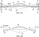
- Figure 3A shows one possible displacement profile illustrating the axial oscillation of the driven end wall 22 of the cavity 16.
- the solid curved line and arrows represent the displacement of the driven end wall 22 at one point in time, and the dashed curved line represents the displacement of the driven end wall 22 one half-cycle later.
- the displacement as shown in this figure and the other figures is exaggerated.
- the actuator 40 is not rigidly mounted at its perimeter, and is instead suspended by the ring-shaped isolator 30, the actuator 40 is free to oscillate about its center of mass in its fundamental mode. In this fundamental mode, the amplitude of the displacement oscillations of the actuator 40 is substantially zero at an annular displacement node 42 located between the center of the driven end wall 22 and the side wall 18.
- a central displacement anti-node 43 exists near the center of the actuator 40 and a peripheral displacement anti-node 43' exists near the perimeter of the actuator 40.
- the central displacement anti-node 43 is represented by the dashed curve after one half-cycle.
- Figure 3B shows one possible pressure oscillation profile illustrating the pressure oscillation within the cavity 16 resulting from the axial displacement oscillations shown in Figure 3A .
- the solid curved line and arrows represent the pressure at one point in time.
- the amplitude of the pressure oscillations has a peripheral pressure anti-node 45' near the side wall 18 of the cavity 16.
- the amplitude of the pressure oscillations is substantially zero at the annular pressure node 44 between the central pressure anti-node 45 and the peripheral pressure anti-node 45'.
- the amplitude of the pressure oscillations as represented by the dashed line that has a negative central pressure anti-node 47 near the center of the cavity 16 with a peripheral pressure anti-node 47' and the same annular pressure node 44.
- the radial dependence of the amplitude of the pressure oscillations in the cavity 16 may be approximated by a Bessel function of the first kind.
- the pressure oscillations described above result from the radial movement of the fluid in the cavity 16 and so will be referred to as the "radial pressure oscillations" of the fluid within the cavity 16 as distinguished from the axial displacement oscillations of the actuator 40.
- the radial dependence of the amplitude of the axial displacement oscillations of the actuator 40 should approximate a Bessel function of the first kind so as to match more closely the radial dependence of the amplitude of the desired pressure oscillations in the cavity 16 (the “mode-shape” of the pressure oscillation).
- the mode-shape of the displacement oscillations substantially matches the mode-shape of the pressure oscillations in the cavity 16, thus achieving mode-shape matching or, more simply, mode-matching.
- the axial displacement oscillations of the actuator 40 and the corresponding pressure oscillations in the cavity 16 have substantially the same relative phase across the full surface of the actuator 40, wherein the radial position of the annular pressure node 44 of the pressure oscillations in the cavity 16 and the radial position of the annular displacement node 42 of the axial displacement oscillations of actuator 40 are substantially coincident.
- the radius of the actuator should preferably be greater than the radius of the annular pressure node 44 to optimize mode-matching.
- the radius of the annular pressure node 44 would be approximately 0.63 of the radius from the center of the end wall 22 to the side wall 18, i.e., the radius of the cavity 16 ("r"), as shown in Figure 2A . Therefore, the radius of the actuator 40 (r act ) should preferably satisfy the following inequality: r act ⁇ 0.63 r .
- the ring-shaped isolator 30 may be a flexible membrane that enables the edge of the actuator 40 to move more freely, as described above, by bending and stretching in response to the vibration of the actuator 40 as shown by the displacement at the peripheral displacement anti-node 43' in Figure 3A .
- the isolator 30 overcomes the potential damping effects of the side wall 18 on the actuator 40 by providing a low mechanical impedance support between the actuator 40 and the cylindrical wall 11 of the disc pump 10, thereby reducing the damping of the axial oscillations at the peripheral displacement anti-node 43' of the actuator 40. Essentially, the isolator 30 minimizes the energy being transferred from the actuator 40 to the side wall 18 with the outer peripheral edge of the isolator 30 remaining substantially stationary.
- the annular displacement node 42 will remain substantially aligned with the annular pressure node 44 to maintain the mode-matching condition of the disc pump 10.
- the axial displacement oscillations of the driven end wall 22 continue to efficiently generate oscillations of the pressure within the cavity 16 from the central pressure anti-nodes 45, 47 to the peripheral pressure anti-nodes 45', 47' at the side wall 18 as shown in Figure 3B .
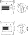
- Figure 4A is a detail view of a portion of the disc pump 10 that includes a strain gauge 50 mounted on the isolator 30 of the disc pump 10.
- the isolator 30 comprises a flexible printed circuit material.
- the strain gauge 50 is attached to the isolator 30 and may be used to compute the displacement of the edge of the actuator 40.
- the strain gauge 50 indirectly measures the displacement of the edge of the actuator 40, thereby alleviating the need to include a sensor on the substrate 28.
- the strain gauge 50 measures the strain, i.e., deformation, of the isolator 30 and the measured deformation of the isolator 30 is used to derive the displacement of the edge of the actuator 40.
- the strain gauge 50 may comprise a metallic pattern that is integrated into the flexible printed circuit material that forms the isolator 30.
- the strain gauge 50 is integral to the isolator 30 so that the strain gauge 50 deforms as the isolator 30 deforms.
- the strain gauge 50 is affixed to the surface of the isolator 30. The deformation of the strain gauge 50 results in a change in the electrical resistance of the strain gauge 50, which can be measured using, for example, a Wheatstone bridge. The change in electrical resistance is related to the deformation of the isolator 30 and, therefore, the displacement of the actuator 40, by a gauge factor. As described in more detail below, the displacement of the edge of the actuator 40 and the associated pressure differential across the disc pump 10 can be determined by analyzing the changes in the electrical resistance of the strain gauge 50.
- the strain gauge 50 is integral to the isolator 30 and formed within the isolator 30 during the manufacturing process.
- the strain gauge 50 may be formed by circuit elements included in an etched copper layer of a flexible printed circuit board material.
- the strain gauge 50 may be manufactured separately and attached to the isolator 30 during the assembly of the disc pump 10.
- Figure 4B is a detail view of a section of a disc pump 10 that shows the strain gauge 50 in a deformed state.
- the strain gauge 50 of Figure 4B has a length (l 2 ) that is longer than the initial length (l 1 ) of the strain gauge 50 in its non-deformed state.
- Figure 4C is a side, detail view of a cross section of the portion of the disc pump 10 shown in Figure 4A
- Figure 4D is a side, detail view of a cross section of the portion of the disc pump 10 shown in Figure 4B .
- the initial length (l 1 ) of the portion of the isolator 30 shown in Figure 4D is known and the deformed length (l 2 ) of the portion of the isolator can be computed by analyzing the change in the electrical resistance of the strain gauge 50 .
- the displacement ( ⁇ y) of the edge of the actuator 40 may be computed by considering the three dimensions (l 1 , l 2 and ⁇ y) as the three sides of a right triangle.
- the displacement ( ⁇ y) of the edge of the actuator 40 is a function of both the bending of the actuator 40 in response to a piezoelectric drive signal and the bulk displacement of the actuator 40 resulting from the difference in pressure on either side of the actuator 40.
- the displacement of the edge of the actuator 40 that results from the bending of the actuator 40 changes at a high frequency that corresponds to the resonant frequency of the disc pump 10.
- the displacement of the edge of actuator 40 that results from a difference in pressure on opposing sides of the actuator 40, the pressure-related displacement of the actuator 40 may be viewed as a quasi-static displacement that changes much more gradually as the disc pump 10 supplies pressure to (or removes pressure from) the load 38.
- the pressure-related displacement ( ⁇ y) of the edge of the actuator 40 bears a direct correlation to the pressure differential across the actuator 40 and the corresponding pressure differential across the disc pump 10.
- non-linear spring characteristics of an isolator may also be determined in order to equate the pressure-related displacement of the edge of the actuator 40 to the pressure differential across the disc pump system 100.
- the displacement ( ⁇ y) may be measured or calculated in real-time or utilizing a specified sampling frequency of strain gauge data to determine the position of the edge of the actuator 40 relative to the substrate 28.
- the position of the edge of the actuator 40 is computed as an average or mean position over a given time period to indicate the displacement ( ⁇ y) resulting from the pressure differential rather than the displacement ( ⁇ y) resulting from the bending of the actuator 40.
- the reduced pressure within the cavity 16 of the disc pump 10 may be determined by sensing the displacement ( ⁇ y) of the edge of the actuator 40 without the need for pressure sensors that directly measure the pressure provided to a load.
- the disc pump 10 of Figure 1A is shown with the valves 29, 32, both of which are substantially similar in structure as represented, for example, by a valve 110 shown in Figures 7A-7D and having a center portion 111 shown in Figure 5B .
- the following description associated with Figures 5-9 are all based on the function of a single valve 110 that may be positioned in any one of the apertures 27, 31 of the disc pump 10.
- Figure 6 shows a graph of the pressure oscillations of fluid within the disc pump 10 as shown in Figure 3B .
- the valve 110 allows fluid to flow in only one direction as described above.
- the valve 110 may be a check valve or any other valve that allows fluid to flow in only one direction. Some valve types may regulate fluid flow by switching between an open and closed position.
- valves 29, 32 For such valves to operate at the high frequencies generated by the actuator 40, the valves 29, 32 must have an extremely fast response time such that they are able to open and close on a timescale significantly shorter than the timescale of the pressure variation.
- One embodiment of the valves 29, 32 achieves this by employing an extremely light flap valve which has low inertia and consequently is able to move rapidly in response to changes in relative pressure across the valve structure.
- valve 110 is such a flap valve for the disc pump 10 according to an illustrative embodiment.
- the valve 110 comprises a substantially cylindrical wall 112 that is ring-shaped and closed at one end by a retention plate 114 and at the other end by a sealing plate 116.
- the inside surface of the wall 112, the retention plate 114, and the sealing plate 116 form a cavity 115 within the valve 110.
- the valve 110 further comprises a substantially circular flap 117 disposed between the retention plate 114 and the sealing plate 116, but adjacent the sealing plate 116.
- the circular flap 117 may be disposed adjacent the retention plate 114 in an alternative embodiment as will be described in more detail below, and in this sense the flap 117 is considered to be "biased" against either one of the sealing plate 116 or the retention plate 114.
- the peripheral portion of the flap 117 is sandwiched between the sealing plate 116 and the ring-shaped wall 112 so that the motion of the flap 117 is restrained in the plane substantially perpendicular the surface of the flap 117.
- the motion of the flap 117 in such plane may also be restrained by the peripheral portion of the flap 117 being attached directly to either the sealing plate 116 or the wall 112, or by the flap 117 being a close fit within the ring-shaped wall 112, in an alternative embodiment.
- the remainder of the flap 117 is sufficiently flexible and movable in a direction substantially perpendicular to the surface of the flap 117, so that a force applied to either surface of the flap 117 will motivate the flap 117 between the sealing plate 116 and the retention plate 114.
- the retention plate 114 and the sealing plate 116 both have holes 118 and 120, respectively, which extend through each plate.
- the flap 117 also has holes 122 that are generally aligned with the holes 118 of the retention plate 114 to provide a passage through which fluid may flow as indicated by the dashed arrows 124 in Figures 5B and 8A .
- the holes 122 in the flap 117 may also be partially aligned, i.e., having only a partial overlap, with the holes 118 in the retention plate 114.
- the holes 118, 120, 122 are shown to be of substantially uniform size and shape, they may be of different diameters or even different shapes without limiting the scope of the invention.
- the holes 118 and 120 form an alternating pattern across the surface of the plates as shown by the solid and dashed circles, respectively, in Figure 7D .
- the holes 118, 120, 122 may be arranged in different patterns without affecting the operation of the valve 110 with respect to the functioning of the individual pairings of holes 118, 120, 122 as illustrated by individual sets of the dashed arrows 124.
- the pattern of holes 118, 120, 122 may be designed to increase or decrease the number of holes to control the total flow of fluid through the valve 110 as required. For example, the number of holes 118, 120, 122 may be increased to reduce the flow resistance of the valve 110 to increase the total flow rate of the valve 110.
- the center portion 111 of the valve 110 illustrates how the flap 117 is motivated between the sealing plate 116 and the retention plate 114 when a force is applied to either surface of the flap 117.
- the valve 110 is in a "normally closed” position because the flap 117 is disposed adjacent the sealing plate 116 where the holes 122 of the flap are offset or not aligned with the holes 118 of the sealing plate 116.
- this "normally closed” position the flow of fluid through the sealing plate 116 is substantially blocked or covered by the non-perforated portions of the flap 117 as shown in Figures 7A and 7B .
- valve 110 moves from the normally closed position to an "open" position over a time period, i.e., an opening time delay (T o ), allowing fluid to flow in the direction indicated by the dashed arrows 124.
- T o opening time delay
- a closing time delay T c
- the flap 117 may be biased against the retention plate 114 with the holes 118, 122 aligned in a "normally open” position. In this embodiment, applying positive pressure against the flap 117 will be necessary to motivate the flap 117 into a "closed” position.
- the operation of the valve 110 is a function of the change in direction of the differential pressure ( ⁇ P) of the fluid across the valve 110.
- the differential pressure has been assigned a negative value (- ⁇ P) as indicated by the downward pointing arrow.
- - ⁇ P negative value
- the fluid pressure at the outside surface of the retention plate 114 is greater than the fluid pressure at the outside surface of the sealing plate 116.
- This negative differential pressure (- ⁇ P) drives the flap 117 into the fully closed position as described above wherein the flap 117 is pressed against the sealing plate 116 to block the holes 120 in the sealing plate 116, thereby substantially preventing the flow of fluid through the valve 110.
- the changing differential pressure cycles the valve 110 between closed and open positions based on the direction (i.e., positive or negative) of the differential pressure across the valve 110. It should be understood that the flap 117 could be biased against the retention plate 114 in an open position when no differential pressure is applied across the valve 110, i.e., the valve 110 would then be in a "normally open” position.
- the operation of the valve 110 is a function of the change in direction of the differential pressure ( ⁇ P) of the fluid across the valve 110.
- the differential pressure ( ⁇ P) is assumed to be substantially uniform across the entire surface of the retention plate 114 because (1) the diameter of the retention plate 114 is small relative to the wavelength of the pressure oscillations in the cavity 115, and (2) the valve 110 is located near the center of the cavity 16 where the amplitude of the positive central pressure anti-node 45 is relatively constant as indicated by the positive square-shaped portion 55 of the positive central pressure anti-node 45 and the negative square-shaped portion 65 of the negative central pressure anti-node 47 shown in Figure 6 . Therefore, there is virtually no spatial variation in the pressure across the center portion 111 of the valve 110.
- Figure 9A further illustrates the dynamic operation of the valve 110 when it is subject to a differential pressure that varies in time between a positive value (+ ⁇ P) and a negative value (- ⁇ P). While in practice the time-dependence of the differential pressure across the valve 110 may be approximately sinusoidal, the time-dependence of the differential pressure across the valve 110 is approximated as varying in the square-wave form shown in Figure 9A to facilitate explanation of the operation of the valve.
- the positive differential pressure 55 is applied across the valve 110 over the positive pressure time period (tp+) and the negative differential pressure 65 is applied across the valve 110 over the negative pressure time period (tp-) of the square wave.
- Figure 9B illustrates the motion of the flap 117 in response to this time-varying pressure.
- the retention plate 114 and the sealing plate 116 should be strong enough to withstand the fluid pressure oscillations to which they are subjected without significant mechanical deformation.
- the retention plate 114 and the sealing plate 116 may be formed from any suitable rigid material, such as glass, silicon, ceramic, or metal.
- the holes 118, 120 in the retention plate 114 and the sealing plate 116 may be formed by any suitable process including chemical etching, laser machining, mechanical drilling, powder blasting, and stamping.
- the retention plate 114 and the sealing plate 116 are formed from sheet steel between 100 and 200 microns thick, and the holes 118, 120 therein are formed by chemical etching.
- the flap 117 may be formed from any lightweight material, such as a metal or polymer film.
- the flap 117 when fluid pressure oscillations of 20 kHz or greater are present on either the retention plate side or the sealing plate side of the valve 110, the flap 117 may be formed from a thin polymer sheet between 1 micron and 20 microns in thickness.
- the flap 117 may be formed from polyethylene terephthalate (PET) or a liquid crystal polymer film approximately 3 microns in thickness.
- valve 110 as valves 29 and 32.
- the actuator valve 32 gates airflow 232 between the actuator aperture 31 and cavity 16 of the disc pump 10 ( Figure 10A ), while end valve 29 gates airflow between the cavity 16 and the outlet aperture 27 of the disc pump 10 ( Figure 10B ).
- Each of the figures also shows the pressure generated in the cavity 16 as the actuator 40 oscillates.
- Both of the valves 29 and 32 are located near the center of the cavity 16 where the amplitudes of the positive and negative central pressure anti-nodes 45 and 47, respectively, are relatively constant as indicated by the positive and negative square-shaped portions 55 and 65, respectively.
- valves 29 and 32 are both biased in the closed position as shown by the flap 117 and operate as described above when the flap 117 is motivated to the open position as indicated by flap 117'.
- the figures also show an exploded view of the positive and negative square-shaped portions 55, 65 of the central pressure anti-nodes 45, 47 and their simultaneous impact on the operation of both valves 29, 32 and the corresponding airflow 229 and 232, respectively, generated through each one.
- the actuator aperture 31 of the disc pump 10 may be supplied with air at ambient pressure while the outlet aperture 27 of the disc pump 10 is pneumatically coupled to a load (not shown) that becomes pressurized through the action of the disc pump 10.
- the actuator aperture 31 of the disc pump 10 may be pneumatically coupled to a load (not shown) that becomes depressurized to generate a negative pressure in the load, such as a wound dressing, through the action of the disc pump 10.
- the square-shaped portion 55 of the positive central pressure anti-node 45 is generated within the cavity 16 by the vibration of the actuator 40 during one half of the disc pump cycle as described above.
- the square-shaped portion 55 of the positive central anti-node 45 creates a positive differential pressure across the end valve 29 and a negative differential pressure across the actuator valve 32.
- the actuator valve 32 begins closing and the end valve 29 begins opening so that the actuator valve 32 blocks the airflow 232x through the actuator aperture 31, while the end valve 29 opens to release air from within the cavity 16 allowing the airflow 229 to exit the cavity 16 through the outlet aperture 27.
- the airflow 229 at the outlet aperture 27 of the disc pump 10 increases to a maximum value dependent on the design characteristics of the end valve 29 ( Figure 11A ).
- the opened end valve 29 allows airflow 229 to exit the disc pump cavity 16 ( Figure 11B ) while the actuator valve 32 is closed.
- the positive differential pressure across end valve 29 begins to decrease, the airflow 229 begins to drop until the differential pressure across the end valve 29 reaches zero.
- the differential pressure across the end valve 29 falls below zero, the end valve 29 begins to close allowing some back-flow 329 of air through the end valve 29 until the end valve 29 is fully closed to block the airflow 229x as shown in Figure 10B .
- the square-shaped portion 65 of the negative central anti-node 47 is generated within the cavity 16 by the vibration of the actuator 40 during the second half of the disc pump cycle as described above.
- the square-shaped portion 65 of the negative central anti-node 47 creates a negative differential pressure across the end valve 29 and a positive differential pressure across the actuator valve 32.
- the actuator valve 32 begins opening and the end valve 29 begins closing so that the end valve 29 blocks the airflow 229x through the outlet aperture 27, while the actuator valve 32 opens allowing air to flow into the cavity 16 as shown by the airflow 232 through the actuator aperture 31.
- the airflow at the outlet aperture 27 of the disc pump 10 is substantially zero except for the small amount of backflow 329 as described above ( Figure 11A ).
- the opened actuator valve 32 allows airflow 232 into the disc pump cavity 16 ( Figure 11B ) while the end valve 29 is closed.
- the airflow 232 begins to drop until the differential pressure across the actuator valve 32 reaches zero.
- the actuator valve 32 begins to close again allowing some back-flow 332 of air through the actuator valve 32 until the actuator valve 32 is fully closed to block the airflow 232x as shown in Figure 10A .
- the actuator aperture 31 of the disc pump 10 is held at ambient pressure and the outlet aperture 27 of the disc pump 10 is pneumatically coupled to a load that becomes pressurized through the action of the disc pump 10, the pressure at the outlet aperture 27 of the disc pump 10 begins to increase until the outlet aperture 27 of the disc pump 10 reaches a maximum pressure at which time the airflow from the actuator aperture 31 to the outlet aperture 27 is negligible, i.e., the "stall" condition.
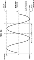
- Figure 12 illustrates the pressures within the cavity 16 and outside the cavity 16 at the actuator aperture 31 and the outlet aperture 27 when the disc pump 10 is in the stall condition. More specifically, the mean pressure in the cavity 16 is approximately IP above the inlet pressure (i.e.
- the pressure at the center of the cavity 16 varies between approximately ambient pressure and approximately ambient pressure plus 2P.
- the pressure oscillation in the cavity 16 results in a sufficient positive differential pressure across either inlet valve 32 or outlet valve 29 to significantly open either valve to allow any airflow through the disc pump 10.
- the synergistic action of the two valves 29, 32 described above is capable of increasing the differential pressure between the outlet aperture 27 and the actuator aperture 31 to a maximum differential pressure of 2P, double that of a single valve disc pump.
- the outlet pressure of the two-valve disc pump 10 increases from ambient in the free-flow mode to a pressure of approximately ambient plus 2P when the disc pump 10 reaches the stall condition.
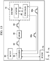
- FIG 13 is a block diagram that illustrates the functionality of the disc pump system of Figure 1A .
- the disc pump system 100 includes a first disc pump 10.
- the disc pump 10 includes a strain gauge 50 that is operable to measure the displacement of an actuator 40, as described above with regard to Figure 1A . It should be understood that other sensors may also be utilized as part of the disc pump system 100.
- the disc pump system 100 comprises a battery 60 to power the disc pump system 100.
- the elements of the disc pump system 100 are interconnected and communicate through wires, paths, traces, leads, and other conductive elements.
- the disc pump system 100 also includes a controller or processor 56 and a driver 58.
- the processor 56 is adapted to communicate with the driver 58.
- the driver 58 is functional to receive a control signal 62 from the processor 56.
- the driver 58 generates a drive signal 64 that energizes the actuator 40 in the first disc pump 10.
- the actuator 40 may include a piezoelectric component that generates the radial pressure oscillations of the fluid within the cavities of the disc pump 10 when energized, causing fluid flow through the cavity to pressurize or depressurize the load as described above.
- the actuators 40 may be driven by an electrostatic or electromagnetic drive mechanism.
- the processor 56 may be coupled to the strain gauge 50 to determine the electrical resistance of the strain gauge 50.
- the isolator 30 When the disc pump 10 is operational, or when a pressure differential is developed across the disc pump 10, the isolator 30 will be deformed as a function of the displacement of the edge of the actuator 40. For example, if the edge of the actuator 40 is displaced from a rest position, the isolator 30 will be under tensile strain. Thus, the change in the electrical resistance of the strain gauge 50 is indicative of the displacement of the actuator 40, as described above.
- the displacement of the edge of the actuator 40 and the corresponding electrical resistance of the strain gauge 50 may have a dynamic value or a static value, depending on whether the pump is operational.
- the strain gauge 50 will return dynamic values of the displacement of the edge of the isolator 40 that can be used to determine the characteristics of the pressure oscillations of the disc pump system 100.
- the strain gauge 50 may be used to determine the pressure differential across the pump in a static condition, i.e., when the disc pump 10 is stopped or when the pump has reached the stall condition.
- the processor 56 utilizes the displacement determination as feedback to adjust the control signal 62 and corresponding drive signals 64 for regulating the pressure at the load 38.
- the processor 56, driver 58, and other control circuitry of the disc pump system 100 may be referred to as an electronic circuit.
- the processor 56 may be circuitry or logic enabled to control functionality of the disc pump 10.
- the processor 56 may function as, or comprise, microprocessors, digital signal processors, application-specific integrated circuits (ASIC), central processing units, digital logic or other devices suitable for controlling an electronic device including one or more hardware and software elements, executing software, instructions, programs, and applications, converting and processing signals and information, and performing other related tasks.
- the processor 56 may be a single chip or integrated with other computing or communications elements.
- the processor 56 may include, or communicate with, a memory.
- the memory may be a hardware element, device, or recording media configured to store data for subsequent retrieval or access at a later time.
- the memory may be static or dynamic memory in the form of random access memory, cache, or other miniaturized storage medium suitable for storage of data, instructions, and information.
- the electronic circuit may be analog circuitry that is configured to perform the same or analogous functionality for measuring the pressure and controlling the displacement of the actuators 40 in the cavities of the disc pump 10, as described above.
- the disc pump system 100 may also include an RF transceiver 70 for communicating information and data relating to the performance of the disc pump system 100.
- the information and data may include, for example, the flow rate, the current pressure measurements, the actual displacement ( ⁇ y) of the actuator 40, and the current life of the battery 60.
- the information and data may be communicated via wireless signals 72 and 74 transmitted from and received by the RF transceiver 70.
- the disc pump system 100 may utilize a communications interface that comprises RF transceiver 70, infrared, or other wired or wireless signals to communicate with one or more external devices.
- the RF transceiver 70 may utilize Bluetooth, WiFi, WiMAX, or other communications standards or proprietary communications systems.
- the RF transceiver 70 may send the signals 72 to a computing device that stores a database of pressure readings for reference by a medical professional.
- the computing device may be a computer, mobile device, or medical equipment device that may perform processing locally or further communicate the information to a central or remote computer for processing of the information and data.
- the RF transceiver 70 may receive the signals 72 for externally regulating the pressure generated by the disc pump system 100 at the load 38 based on the motion of the actuators 40.
- the driver 58 is an electrical circuit that energizes and controls the actuator 40.
- the driver 58 may be a high-power transistor, amplifier, bridge, and/or filters for generating a specific waveform as part of the drive signal 64.
- Such a waveform may be configured by the processor 56 and the driver 58 to provide drive signal 64 that causes the actuator 40 to vibrate in an oscillatory motion at the frequency (f), as described in more detail above.
- the oscillatory displacement motion of the actuator 40 generates the radial pressure oscillations of the fluid within the cavities of the disc pump 10 in response to the drive signal 64 to generate pressure at the load 38.
- the disc pump system 100 may include a user interface for displaying information to a user.
- the user interface may include a display, audio interface, or tactile interface for providing information, data, or signals to a user.
- a miniature LED screen may display the pressure being applied by the disc pump system 100.
- the user interface may also include buttons, dials, knobs, or other electrical or mechanical interfaces for adjusting the performance of the disc pump, and particularly, the reduced pressure generated. For example, the pressure may be increased or decreased by adjusting a knob or other control element that is part of the user interface.
- the use of a strain gauge 50 can negate the need for a separate pressure sensor to measure the displacement of an actuator in a twin-valve or other disc pump.
- the measured displacement can be used to determine the pressure differential generated by the disc pump.
- the strain gauge can be manufactured directly onto the isolator and used to directly measure the strain on the isolator.
- the strain on the isolator may be used to determine the corresponding displacement of the actuator, which enables the computation of the differential pressure generated by the disc pump.
- null electrical resistance of the strain gauge 50 By measuring the null electrical resistance of the strain gauge 50 when the actuator 40 is in a rest, or unbiased position, and comparing the null electrical resistance of the strain gauge 50 to the electrical resistance of the strain gauge 50 over time, data can also be gathered to indicate damage or the effect of wear on the isolator. It is noted that, in this embodiment, the null electrical resistance of the strain gauge 50 may be measured before the disc pump system 100 is coupled to the load 38 to ensure that there is not an externally generated, or pre-existing pressure differential across the actuator 40.
- the strain gauge data can be monitored and evaluated over time to detect changes in the resiliency of the isolator 30.
- this strain gauge data may be gathered to indicate the condition of the isolator 30.
- strain gauge data that indicates that the resiliency of the isolator 30 is diminishing may indicate a worn or damaged isolator 30.
- strain gauge data indicating that there is less strain, or less deformation of the isolator 30 despite the application of a drive signal to the actuator 40 may indicate a pump defect, such as delamination of the isolator 30.
- the rate of change of pressure which can be measured using data gathered by the strain gauge, may be used to indicate a flow rate of the disc pump 10.
Claims (15)
- Scheibenpumpensystem (10), das umfasst:einen Pumpenkörper, der eine im Wesentlichen zylindrische Form aufweist, die einen Hohlraum (16) zum Enthalten eines Fluids definiert, wobei der Hohlraum (16) von einer Seitenwand (18) gebildet ist, die an beiden Enden durch im Wesentlichen kreisförmige Endwände (20, 22) geschlossen ist, wobei mindestens eine der kreisförmigen Endwände eine angetriebene Endwand (22) ist, die einen zentralen Abschnitt und einen peripheren Abschnitt, der sich radial von dem zentralen Abschnitt der angetriebenen Endwand (22) nach außen erstreckt, aufweist;einen Aktuator (40), der betrieblich mit dem zentralen Abschnitt der angetriebenen Endwand (22) assoziiert ist, um eine oszillierende Bewegung der angetriebenen Endwand (22) zu veranlassen, wodurch Verlagerungsoszillationen der angetriebenen Endwand (22) in eine Richtung im Wesentlichen senkrecht dazu erzeugt werden; dadurch gekennzeichnet, dassein Isolator (30) zwischen dem peripheren Abschnitt der angetriebenen Endwand (22) und der Seitenwand (18) positioniert ist, um Dämpfen der Verlagerungsoszillationen zu reduzieren, wobei der Isolator (30) ein biegsames Material umfasst, das sich als Reaktion auf die oszillierende Bewegung der angetriebenen Endwand (22) streckt und zusammenzieht;eine erste Öffnung (27), die in einer der Endwände (20, 22) angeordnet ist und sich durch den Pumpenkörper erstreckt;eine zweite Öffnung (31), die in dem Pumpenkörper angeordnet ist und sich durch den Pumpenkörper erstreckt;ein Ventil (29, 32), das entweder in der ersten Öffnung (27) oder der zweiten Öffnung (31) angeordnet ist, oder ein erstes Ventil (29), das in der ersten Öffnung (27) angeordnet ist, und ein zweites Ventil (32), das in der zweiten Öffnung (31) angeordnet ist; undeinen Dehnungsmesser (50), der mit dem biegsamen Material des Isolators integral und damit betrieblich assoziiert ist, um die Verlagerungsoszillationen der angetriebenen Endwand (22) zu messen, um eine Druckänderung über den Aktuator zu bestimmen.
- Scheibenpumpensystem (10) nach Anspruch 1, wobei das biegsame Material ein biegsames Leiterplattenmaterial umfasst.
- Scheibenpumpensystem (10) nach Anspruch 1, wobei der Dehnungsmesser (50) mit einem Schaltungselement des Isolators (30) gekoppelt ist.
- Scheibenpumpensystem (10) nach Anspruch 1, das weiter einen Prozessor (56) umfasst, der elektrisch mit dem Dehnungsmesser (50) gekoppelt ist, wobei der Prozessor (56) betreibbar ist, um ein Signal von dem Dehnungsmesser (50) zu empfangen, wobei das Signal die Änderung des elektrischen Widerstands des Dehnungsmessers (50) angibt.
- Scheibenpumpensystem (10) nach Anspruch 4, wobei der Prozessor (56) betreibbar ist, um i); i) und ii); oder i), ii) und iii) der Folgenden auszuführen:i) Bestimmen der Verlagerung der angetriebenen Endwand (22) an einem Knoten, basierend auf dem Signal, das von dem Dehnungsmesser (50) empfangen wird,ii) Bestimmen der mittleren Verlagerung der angetriebenen Endwand (22) über eine Zeitspanne,iii) Bestimmen des Druckunterschieds über die Scheibenpumpe basierend auf der mittleren Verlagerung der angetriebenen Endwand (22) über eine Zeitspanne.
- Scheibenpumpensystem (10) nach Anspruch 4, das weiter einen Speicher umfasst, wobei der Prozessor (56) betreibbar ist, um Dehnungsmesserdaten basierend auf Signalen zu erzeugen, die von dem Dehnungsmesser (50) erhalten werden, und wobei der Speicher betreibbar ist, um die Dehnungsmesserdaten zu speichern.
- Scheibenpumpensystem (10) nach Anspruch 6, wobei:der Hohlraum des Pumpenkörpers fluidisch mit einer Last über eine der ersten und zweiten Öffnungen gekoppelt ist,der Prozessor (56) betreibbar ist, um erste Daten von dem Dehnungsmesser (50) in einem ersten Zeitpunkt zu empfangender Prozessor (56) betreibbar ist, um zweite Daten von dem Dehnungsmesser (50) in einem zweiten Zeitpunkt zu empfangen;der Prozessor (56) betreibbar ist, um die ersten Daten mit den zweiten Daten zu vergleichen; undder Prozessor (56) betreibbar ist, um basierend auf dem Vergleich der ersten Daten mit den zweiten Daten zu bestimmen, dass der Isolator (30) beschädigt ist.
- Scheibenpumpensystem nach Anspruch 7, wobei der Prozessor (56) betreibbar ist, um das Scheibenpumpensystem als Reaktion auf das Bestimmen, dass der Isolator (30) beschädigt ist, zu stoppen.
- Verfahren zum Messen der Verlagerung einer angetriebenen Endwand (22) einer Scheibenpumpe (10), wobei das Verfahren umfasst:
Messen einer Änderung des elektrischen Widerstands eines Dehnungsmessers (50), wobei der Dehnungsmesser (50) mit einem Isolator (30) der Scheibenpumpe (10) integral und betrieblich damit assoziiert ist, um die Verlagerung der angetriebenen Endwand (22) zu messen, und wobei die angetriebene Endwand (22) einen Aktuator (40) umfasst, der innerhalb der Scheibenpumpe (10) auf dem Isolator (30) montiert ist, wobei die Scheibenpumpe (10) umfasst:einen Pumpenkörper, der eine im Wesentlichen zylindrische Form aufweist, die einen Hohlraum (16) zum Enthalten eines Fluids definiert, wobei der Hohlraum (16) von einer Seitenwand (18) gebildet ist, die an beiden Enden durch im Wesentlichen kreisförmige Endwände (20, 22) geschlossen ist, wobei mindestens eine der kreisförmigen Endwände die angetriebene Endwand (22) ist, die einen zentralen Abschnitt und einen peripheren Abschnitt, der sich radial von dem zentralen Abschnitt der angetriebenen Endwand (22) nach außen erstreckt, aufweist;den Aktuator (40), der betrieblich mit dem zentralen Abschnitt der angetriebenen Endwand (22) assoziiert ist, um eine oszillierende Bewegung der angetriebenen Endwand (22) zu verursachen, wodurch Verlagerungsoszillationen der angetriebenen Endwand in eine Richtung im Wesentlichen senkrecht dazu, mit einem ringförmigen Knoten zwischen der Mitte der angetriebenen Endwand (22) und der Seitenwand bei Verwendung erzeugt werden;den Isolator (30), der zwischen dem peripheren Abschnitt der angetriebenen Endwand (22) und der Seitenwand (18) eingefügt ist, um Dämpfen der Verlagerungsoszillationen zu reduzieren, wobei der Isolator (30) ein biegsames Material umfasst, das sich als Reaktion auf die oszillierende Bewegung der angetriebenen Endwand (22) streckt und zusammenzieht;eine erste Öffnung (27), die an einer Stelle in einer der Endwände, die nicht an dem ringförmigen Knoten ist und sich durch den Pumpenkörper erstreckt, angeordnet ist;eine zweite Öffnung (31), die an einer anderen Stelle in dem Pumpenkörper als der Stelle der ersten Öffnung angeordnet ist und sich durch den Pumpenkörper erstreckt; undein Ventil (29, 32), das in der ersten Öffnung (27) oder der zweiten Öffnung (31) angeordnet ist, oder ein erstes Ventil (29), das in der ersten Öffnung (27) angeordnet ist, und ein zweites Ventil (32), das in der zweiten Öffnung (31) angeordnet ist, wodurch die Verlagerungsoszillationen entsprechende Druckoszillationen des Fluids innerhalb des Hohlraums des Pumpenkörpers verursachen, die veranlassen, dass bei Verwendung Fluid durch die erste Öffnung (27) und die zweite Öffnung (31) fließt. - Verfahren nach Anspruch 9, das weiter das Korrelieren der Änderung des elektrischen Widerstands des Dehnungsmessers (50) mit der Verlagerung der angetriebenen Endwand (22) oder das Korrelieren der Änderung des elektrischen Widerstands des Dehnungsmessers (50) mit einem Druck, der zu einer Last bereitgestellt wird, umfasst.
- Verfahren nach Anspruch 9, wobei das biegsame Material ein biegsames Leiterplattenmaterial umfasst.
- Verfahren nach Anspruch 9, das weiter das Kommunizieren eines Signals zu einem Prozessor (56) umfasst, wobei das Signal die Änderung des elektrischen Widerstands des Dehnungsmessers (50) angibt.
- Verfahren nach Anspruch 12, das weiter das Verwenden des Prozessors (56) zum Ausführen von i); i) und ii); oder i), ii) und iii) der Folgenden umfasst:i) Bestimmen der Verlagerung der angetriebenen Endwand (22) basierend auf dem Signal,ii) Bestimmen einer mittleren Verlagerung der angetriebenen Endwand (22) über eine Zeitspanne,iii) Bestimmen des Druckunterschieds über die Scheibenpumpe basierend auf der mittleren Verlagerung der angetriebenen Endwand (22) über eine Zeitspanne.
- Verfahren nach Anspruch 12, wobei das Signal ein erstes Signal ist, und das weiter das Empfangen des ersten Signals von dem Dehnungsmesser (50) in einem ersten Zeitpunkt umfasst
das Empfangen eines zweiten Signals von dem Dehnungsmesser (50) in einem zweiten Zeitpunkt;
das Vergleichen des ersten Signals mit dem zweiten Signal; und
basierend auf dem Vergleich des ersten Signals mit dem zweiten Signal das Bestimmen, dass der Isolator (30) beschädigt ist. - Verfahren nach Anspruch 14, das weiter das Stoppen der Scheibenpumpe (10) als Reaktion auf das Bestimmen, dass der Isolator (30) beschädigt ist, umfasst.
Applications Claiming Priority (2)
| Application Number | Priority Date | Filing Date | Title |
|---|---|---|---|
| US201261597463P | 2012-02-10 | 2012-02-10 | |
| PCT/US2013/025181 WO2013119837A2 (en) | 2012-02-10 | 2013-02-07 | Systems and methods for monitoring reduced pressure supplied by a disc pump system |
Publications (2)
| Publication Number | Publication Date |
|---|---|
| EP2812574A2 EP2812574A2 (de) | 2014-12-17 |
| EP2812574B1 true EP2812574B1 (de) | 2021-07-28 |
Family
ID=47739520
Family Applications (1)
| Application Number | Title | Priority Date | Filing Date |
|---|---|---|---|
| EP13705084.5A Active EP2812574B1 (de) | 2012-02-10 | 2013-02-07 | Systeme und verfahren zur überwachung von durch ein scheibenpumpsystem abgegebenem reduziertem druck |
Country Status (6)
| Country | Link |
|---|---|
| US (1) | US9234518B2 (de) |
| EP (1) | EP2812574B1 (de) |
| JP (1) | JP2015510072A (de) |
| AU (1) | AU2013216967A1 (de) |
| CA (1) | CA2863847A1 (de) |
| WO (1) | WO2013119837A2 (de) |
Families Citing this family (16)
| Publication number | Priority date | Publication date | Assignee | Title |
|---|---|---|---|---|
| US7753894B2 (en) | 2004-04-27 | 2010-07-13 | Smith & Nephew Plc | Wound cleansing apparatus with stress |
| WO2009066106A1 (en) | 2007-11-21 | 2009-05-28 | Smith & Nephew Plc | Wound dressing |
| US9084845B2 (en) | 2011-11-02 | 2015-07-21 | Smith & Nephew Plc | Reduced pressure therapy apparatuses and methods of using same |
| TW201326773A (zh) * | 2011-12-30 | 2013-07-01 | Ind Tech Res Inst | 壓力感測器的電性量測裝置及其方法 |
| RU2014138377A (ru) | 2012-03-20 | 2016-05-20 | СМИТ ЭНД НЕФЬЮ ПиЭлСи | Управление работой системы терапии пониженным давлением, основанное на определении порога продолжительности включения |
| US9427505B2 (en) | 2012-05-15 | 2016-08-30 | Smith & Nephew Plc | Negative pressure wound therapy apparatus |
| AU2015370583B2 (en) | 2014-12-22 | 2020-08-20 | Smith & Nephew Plc | Negative pressure wound therapy apparatus and methods |
| JP6572619B2 (ja) * | 2015-05-11 | 2019-09-11 | 株式会社村田製作所 | ブロア |
| US10132706B2 (en) * | 2015-09-28 | 2018-11-20 | Apple Inc. | Waterproof barometric sensor in an electronic device |
| US10466047B2 (en) * | 2015-09-30 | 2019-11-05 | Apple Inc. | Barometric sensor integration in a water resistant electronic device |
| JP7231227B2 (ja) * | 2017-02-22 | 2023-03-01 | コーネル ユニヴァーシティー | 小さい切開創を機械式に管理、保護及び吸引するための機械式真空ドレッシング |
| US11839527B2 (en) | 2017-12-06 | 2023-12-12 | Cornell University | Manually-operated negative pressure wound therapy (NPWT) bandage with improved pump efficiency, automatic pressure indicator and automatic pressure limiter |
| US10119869B1 (en) * | 2017-12-21 | 2018-11-06 | Tactotek Oy | Method for manufacturing a strain gauge device, a strain gauge device, and the use of the device |
| WO2019159501A1 (ja) * | 2018-02-16 | 2019-08-22 | 株式会社村田製作所 | 流体制御装置 |
| DE102018203098B3 (de) * | 2018-03-01 | 2019-06-19 | Infineon Technologies Ag | MEMS-Sensor |
| WO2022025230A1 (ja) * | 2020-07-31 | 2022-02-03 | Tdk株式会社 | ポンプ及び流体制御装置 |
Family Cites Families (129)
| Publication number | Priority date | Publication date | Assignee | Title |
|---|---|---|---|---|
| US1355846A (en) | 1920-02-06 | 1920-10-19 | David A Rannells | Medical appliance |
| US2547758A (en) | 1949-01-05 | 1951-04-03 | Wilmer B Keeling | Instrument for treating the male urethra |
| US2632443A (en) | 1949-04-18 | 1953-03-24 | Eleanor P Lesher | Surgical dressing |
| GB692578A (en) | 1949-09-13 | 1953-06-10 | Minnesota Mining & Mfg | Improvements in or relating to drape sheets for surgical use |
| US2682873A (en) | 1952-07-30 | 1954-07-06 | Johnson & Johnson | General purpose protective dressing |
| NL189176B (nl) | 1956-07-13 | 1900-01-01 | Hisamitsu Pharmaceutical Co | Pleister op basis van een synthetische rubber. |
| US2969057A (en) | 1957-11-04 | 1961-01-24 | Brady Co W H | Nematodic swab |
| US3066672A (en) | 1960-09-27 | 1962-12-04 | Jr William H Crosby | Method and apparatus for serial sampling of intestinal juice |
| US3367332A (en) | 1965-08-27 | 1968-02-06 | Gen Electric | Product and process for establishing a sterile area of skin |
| US3520300A (en) | 1967-03-15 | 1970-07-14 | Amp Inc | Surgical sponge and suction device |
| US3568675A (en) | 1968-08-30 | 1971-03-09 | Clyde B Harvey | Fistula and penetrating wound dressing |
| US3682180A (en) | 1970-06-08 | 1972-08-08 | Coilform Co Inc | Drain clip for surgical drain |
| BE789293Q (fr) | 1970-12-07 | 1973-01-15 | Parke Davis & Co | Pansement medico-chirugical pour brulures et lesions analogues |
| US3826254A (en) | 1973-02-26 | 1974-07-30 | Verco Ind | Needle or catheter retaining appliance |
| DE2527706A1 (de) | 1975-06-21 | 1976-12-30 | Hanfried Dr Med Weigand | Einrichtung zum einleiten von kontrastmittel in einen kuenstlichen darmausgang |
| DE2640413C3 (de) | 1976-09-08 | 1980-03-27 | Richard Wolf Gmbh, 7134 Knittlingen | Katheter-Überwachungsgerät |
| NL7710909A (nl) | 1976-10-08 | 1978-04-11 | Smith & Nephew | Samengestelde hechtstrook. |
| GB1562244A (en) | 1976-11-11 | 1980-03-05 | Lock P M | Wound dressing materials |
| US4080970A (en) | 1976-11-17 | 1978-03-28 | Miller Thomas J | Post-operative combination dressing and internal drain tube with external shield and tube connector |
| US4139004A (en) | 1977-02-17 | 1979-02-13 | Gonzalez Jr Harry | Bandage apparatus for treating burns |
| US4184510A (en) | 1977-03-15 | 1980-01-22 | Fibra-Sonics, Inc. | Valued device for controlling vacuum in surgery |
| US4165748A (en) | 1977-11-07 | 1979-08-28 | Johnson Melissa C | Catheter tube holder |
| US4256109A (en) | 1978-07-10 | 1981-03-17 | Nichols Robert L | Shut off valve for medical suction apparatus |
| SE414994B (sv) | 1978-11-28 | 1980-09-01 | Landstingens Inkopscentral | Venkateterforband |
| DE2953373A1 (en) | 1978-12-06 | 1981-01-08 | P Svedman | Device for treating tissues,for example skin |
| US4266545A (en) | 1979-04-06 | 1981-05-12 | Moss James P | Portable suction device for collecting fluids from a closed wound |
| US4284079A (en) | 1979-06-28 | 1981-08-18 | Adair Edwin Lloyd | Method for applying a male incontinence device |
| US4261363A (en) | 1979-11-09 | 1981-04-14 | C. R. Bard, Inc. | Retention clips for body fluid drains |
| US4569348A (en) | 1980-02-22 | 1986-02-11 | Velcro Usa Inc. | Catheter tube holder strap |
| EP0035583B1 (de) | 1980-03-11 | 1985-08-14 | Schmid, Eduard, Dr.Dr.med. | Hauttransplantations-Druckverband |
| US4297995A (en) | 1980-06-03 | 1981-11-03 | Key Pharmaceuticals, Inc. | Bandage containing attachment post |
| US4333468A (en) | 1980-08-18 | 1982-06-08 | Geist Robert W | Mesentery tube holder apparatus |
| US4465485A (en) | 1981-03-06 | 1984-08-14 | Becton, Dickinson And Company | Suction canister with unitary shut-off valve and filter features |
| US4392853A (en) | 1981-03-16 | 1983-07-12 | Rudolph Muto | Sterile assembly for protecting and fastening an indwelling device |
| US4373519A (en) | 1981-06-26 | 1983-02-15 | Minnesota Mining And Manufacturing Company | Composite wound dressing |
| US4392858A (en) | 1981-07-16 | 1983-07-12 | Sherwood Medical Company | Wound drainage device |
| US4419097A (en) | 1981-07-31 | 1983-12-06 | Rexar Industries, Inc. | Attachment for catheter tube |
| AU550575B2 (en) | 1981-08-07 | 1986-03-27 | Richard Christian Wright | Wound drainage device |
| SE429197B (sv) | 1981-10-14 | 1983-08-22 | Frese Nielsen | Anordning for behandling av sar |
| DE3146266A1 (de) | 1981-11-21 | 1983-06-01 | B. Braun Melsungen Ag, 3508 Melsungen | Kombinierte vorrichtung fuer eine medizinische saugdrainage |
| US4551139A (en) | 1982-02-08 | 1985-11-05 | Marion Laboratories, Inc. | Method and apparatus for burn wound treatment |
| US4475909A (en) | 1982-05-06 | 1984-10-09 | Eisenberg Melvin I | Male urinary device and method for applying the device |
| EP0100148B1 (de) | 1982-07-06 | 1986-01-08 | Dow Corning Limited | Medizinischer chirurgischer Wundverband und Verfahren zu seiner Herstellung |
| NZ206837A (en) | 1983-01-27 | 1986-08-08 | Johnson & Johnson Prod Inc | Thin film adhesive dressing:backing material in three sections |
| US4548202A (en) | 1983-06-20 | 1985-10-22 | Ethicon, Inc. | Mesh tissue fasteners |
| US4540412A (en) | 1983-07-14 | 1985-09-10 | The Kendall Company | Device for moist heat therapy |
| US4543100A (en) | 1983-11-01 | 1985-09-24 | Brodsky Stuart A | Catheter and drain tube retainer |
| US4525374A (en) | 1984-02-27 | 1985-06-25 | Manresa, Inc. | Treating hydrophobic filters to render them hydrophilic |
| GB2157958A (en) | 1984-05-03 | 1985-11-06 | Ernest Edward Austen Bedding | Ball game net support |
| US4897081A (en) | 1984-05-25 | 1990-01-30 | Thermedics Inc. | Percutaneous access device |
| US5215522A (en) | 1984-07-23 | 1993-06-01 | Ballard Medical Products | Single use medical aspirating device and method |
| GB8419745D0 (en) | 1984-08-02 | 1984-09-05 | Smith & Nephew Ass | Wound dressing |
| US4872450A (en) | 1984-08-17 | 1989-10-10 | Austad Eric D | Wound dressing and method of forming same |
| US4826494A (en) | 1984-11-09 | 1989-05-02 | Stryker Corporation | Vacuum wound drainage system |
| US4655754A (en) | 1984-11-09 | 1987-04-07 | Stryker Corporation | Vacuum wound drainage system and lipids baffle therefor |
| US4605399A (en) | 1984-12-04 | 1986-08-12 | Complex, Inc. | Transdermal infusion device |
| US5037397A (en) | 1985-05-03 | 1991-08-06 | Medical Distributors, Inc. | Universal clamp |
| US4640688A (en) | 1985-08-23 | 1987-02-03 | Mentor Corporation | Urine collection catheter |
| US4710165A (en) | 1985-09-16 | 1987-12-01 | Mcneil Charles B | Wearable, variable rate suction/collection device |
| US4758220A (en) | 1985-09-26 | 1988-07-19 | Alcon Laboratories, Inc. | Surgical cassette proximity sensing and latching apparatus |
| US4733659A (en) | 1986-01-17 | 1988-03-29 | Seton Company | Foam bandage |
| WO1987004626A1 (en) | 1986-01-31 | 1987-08-13 | Osmond, Roger, L., W. | Suction system for wound and gastro-intestinal drainage |
| US4838883A (en) | 1986-03-07 | 1989-06-13 | Nissho Corporation | Urine-collecting device |
| JPS62281965A (ja) | 1986-05-29 | 1987-12-07 | テルモ株式会社 | カテ−テルおよびカテ−テル用固定部材 |
| GB8621884D0 (en) | 1986-09-11 | 1986-10-15 | Bard Ltd | Catheter applicator |
| GB2195255B (en) | 1986-09-30 | 1991-05-01 | Vacutec Uk Limited | Apparatus for vacuum treatment of an epidermal surface |
| US4743232A (en) | 1986-10-06 | 1988-05-10 | The Clinipad Corporation | Package assembly for plastic film bandage |
| DE3634569A1 (de) | 1986-10-10 | 1988-04-21 | Sachse Hans E | Kondomkatheter, ein harnroehrenkatheter zur verhinderung von aufsteigenden infektionen |
| JPS63135179A (ja) | 1986-11-26 | 1988-06-07 | 立花 俊郎 | 薬物の経皮投与具 |
| GB8628564D0 (en) | 1986-11-28 | 1987-01-07 | Smiths Industries Plc | Anti-foaming agent suction apparatus |
| GB8706116D0 (en) | 1987-03-14 | 1987-04-15 | Smith & Nephew Ass | Adhesive dressings |
| US4787888A (en) | 1987-06-01 | 1988-11-29 | University Of Connecticut | Disposable piezoelectric polymer bandage for percutaneous delivery of drugs and method for such percutaneous delivery (a) |
| US4863449A (en) | 1987-07-06 | 1989-09-05 | Hollister Incorporated | Adhesive-lined elastic condom cathether |
| US5176663A (en) | 1987-12-02 | 1993-01-05 | Pal Svedman | Dressing having pad with compressibility limiting elements |
| US4906240A (en) | 1988-02-01 | 1990-03-06 | Matrix Medica, Inc. | Adhesive-faced porous absorbent sheet and method of making same |
| US4985019A (en) | 1988-03-11 | 1991-01-15 | Michelson Gary K | X-ray marker |
| GB8812803D0 (en) | 1988-05-28 | 1988-06-29 | Smiths Industries Plc | Medico-surgical containers |
| US4919654A (en) | 1988-08-03 | 1990-04-24 | Kalt Medical Corporation | IV clamp with membrane |
| US5000741A (en) | 1988-08-22 | 1991-03-19 | Kalt Medical Corporation | Transparent tracheostomy tube dressing |
| JPH02270874A (ja) | 1989-01-16 | 1990-11-05 | Roussel Uclaf | アザビシクロ化合物及びそれらの塩、それらの製造方法、それらを含有する製薬組成物並びにそれらの薬剤としての使用 |
| GB8906100D0 (en) | 1989-03-16 | 1989-04-26 | Smith & Nephew | Laminates |
| US5100396A (en) | 1989-04-03 | 1992-03-31 | Zamierowski David S | Fluidic connection system and method |
| US4969880A (en) | 1989-04-03 | 1990-11-13 | Zamierowski David S | Wound dressing and treatment method |
| US5527293A (en) | 1989-04-03 | 1996-06-18 | Kinetic Concepts, Inc. | Fastening system and method |
| US5261893A (en) | 1989-04-03 | 1993-11-16 | Zamierowski David S | Fastening system and method |
| US5224843A (en) * | 1989-06-14 | 1993-07-06 | Westonbridge International Ltd. | Two valve micropump with improved outlet |
| US5358494A (en) | 1989-07-11 | 1994-10-25 | Svedman Paul | Irrigation dressing |
| JP2719671B2 (ja) | 1989-07-11 | 1998-02-25 | 日本ゼオン株式会社 | 創傷被覆材 |
| US5232453A (en) | 1989-07-14 | 1993-08-03 | E. R. Squibb & Sons, Inc. | Catheter holder |
| GB2235877A (en) | 1989-09-18 | 1991-03-20 | Antonio Talluri | Closed wound suction apparatus |
| EP0435653B1 (de) | 1989-12-27 | 1994-06-01 | Seiko Epson Corporation | Mikropumpe |
| US5134994A (en) | 1990-02-12 | 1992-08-04 | Say Sam L | Field aspirator in a soft pack with externally mounted container |
| US5092858A (en) | 1990-03-20 | 1992-03-03 | Becton, Dickinson And Company | Liquid gelling agent distributor device |
| US5149331A (en) | 1991-05-03 | 1992-09-22 | Ariel Ferdman | Method and device for wound closure |
| US5278100A (en) | 1991-11-08 | 1994-01-11 | Micron Technology, Inc. | Chemical vapor deposition technique for depositing titanium silicide on semiconductor wafers |
| US5645081A (en) | 1991-11-14 | 1997-07-08 | Wake Forest University | Method of treating tissue damage and apparatus for same |
| US5636643A (en) | 1991-11-14 | 1997-06-10 | Wake Forest University | Wound treatment employing reduced pressure |
| US5279550A (en) | 1991-12-19 | 1994-01-18 | Gish Biomedical, Inc. | Orthopedic autotransfusion system |
| US5167613A (en) | 1992-03-23 | 1992-12-01 | The Kendall Company | Composite vented wound dressing |
| FR2690617B1 (fr) | 1992-04-29 | 1994-06-24 | Cbh Textile | Pansement adhesif transparent. |
| DE4306478A1 (de) | 1993-03-02 | 1994-09-08 | Wolfgang Dr Wagner | Drainagevorrichtung, insbesondere Pleuradrainagevorrichtung, und Drainageverfahren |
| US5342376A (en) | 1993-05-03 | 1994-08-30 | Dermagraphics, Inc. | Inserting device for a barbed tissue connector |
| US6241747B1 (en) | 1993-05-03 | 2001-06-05 | Quill Medical, Inc. | Barbed Bodily tissue connector |
| US5344415A (en) | 1993-06-15 | 1994-09-06 | Deroyal Industries, Inc. | Sterile system for dressing vascular access site |
| US5437651A (en) | 1993-09-01 | 1995-08-01 | Research Medical, Inc. | Medical suction apparatus |
| US5549584A (en) | 1994-02-14 | 1996-08-27 | The Kendall Company | Apparatus for removing fluid from a wound |
| US5607388A (en) | 1994-06-16 | 1997-03-04 | Hercules Incorporated | Multi-purpose wound dressing |
| US5556375A (en) | 1994-06-16 | 1996-09-17 | Hercules Incorporated | Wound dressing having a fenestrated base layer |
| US5664270A (en) | 1994-07-19 | 1997-09-09 | Kinetic Concepts, Inc. | Patient interface system |
| EP0853950B1 (de) | 1994-08-22 | 2002-10-30 | Kinetic Concepts, Inc. | Kanister für Wunddrainagen |
| DE29504378U1 (de) | 1995-03-15 | 1995-09-14 | Mtg Medizinisch Tech Geraeteba | Elektronisch geregelte Niedervakuumpumpe für die Thorax- und Wunddrainage |
| GB9523253D0 (en) | 1995-11-14 | 1996-01-17 | Mediscus Prod Ltd | Portable wound treatment apparatus |
| JPH09149941A (ja) * | 1995-12-01 | 1997-06-10 | Tokai Rika Co Ltd | 体内挿入用医療器具のセンサ |
| US6135116A (en) | 1997-07-28 | 2000-10-24 | Kci Licensing, Inc. | Therapeutic method for treating ulcers |
| GB9719520D0 (en) | 1997-09-12 | 1997-11-19 | Kci Medical Ltd | Surgical drape and suction heads for wound treatment |
| AU755496B2 (en) | 1997-09-12 | 2002-12-12 | Kci Licensing, Inc. | Surgical drape and suction head for wound treatment |
| US6071267A (en) | 1998-02-06 | 2000-06-06 | Kinetic Concepts, Inc. | Medical patient fluid management interface system and method |
| US6488643B1 (en) | 1998-10-08 | 2002-12-03 | Kci Licensing, Inc. | Wound healing foot wrap |
| US6287316B1 (en) | 1999-03-26 | 2001-09-11 | Ethicon, Inc. | Knitted surgical mesh |
| US6856821B2 (en) | 2000-05-26 | 2005-02-15 | Kci Licensing, Inc. | System for combined transcutaneous blood gas monitoring and vacuum assisted wound closure |
| US7799004B2 (en) | 2001-03-05 | 2010-09-21 | Kci Licensing, Inc. | Negative pressure wound treatment apparatus and infection identification system and method |
| US6991643B2 (en) | 2000-12-20 | 2006-01-31 | Usgi Medical Inc. | Multi-barbed device for retaining tissue in apposition and methods of use |
| CA2400895C (en) | 2000-02-24 | 2011-09-13 | Venetec International, Inc. | Universal catheter anchoring system |
| US6540705B2 (en) | 2001-02-22 | 2003-04-01 | Core Products International, Inc. | Ankle brace providing upper and lower ankle adjustment |
| JP4678135B2 (ja) | 2003-06-17 | 2011-04-27 | セイコーエプソン株式会社 | ポンプ |
| GB0508194D0 (en) | 2005-04-22 | 2005-06-01 | The Technology Partnership Plc | Pump |
| EP2185904A2 (de) * | 2007-08-27 | 2010-05-19 | Koninklijke Philips Electronics N.V. | Drucksensor, sensorsonde mit einem drucksensor, medizinische vorrichtung mit einer sensorsonde und verfahren zur herstellung einer sensorsonde |
| BRPI0924510B8 (pt) * | 2009-06-03 | 2022-08-02 | Ttp Ventus Ltd | Bomba |
| WO2012021412A1 (en) * | 2010-08-09 | 2012-02-16 | Kci Licensing, Inc. | System and method for measuring pressure applied by a piezo-electric pump |
-
2013
- 2013-02-07 US US13/762,034 patent/US9234518B2/en active Active
- 2013-02-07 EP EP13705084.5A patent/EP2812574B1/de active Active
- 2013-02-07 CA CA2863847A patent/CA2863847A1/en not_active Abandoned
- 2013-02-07 WO PCT/US2013/025181 patent/WO2013119837A2/en active Application Filing
- 2013-02-07 JP JP2014556681A patent/JP2015510072A/ja active Pending
- 2013-02-07 AU AU2013216967A patent/AU2013216967A1/en not_active Abandoned
Also Published As
| Publication number | Publication date |
|---|---|
| US9234518B2 (en) | 2016-01-12 |
| WO2013119837A3 (en) | 2014-08-07 |
| WO2013119837A2 (en) | 2013-08-15 |
| EP2812574A2 (de) | 2014-12-17 |
| AU2013216967A1 (en) | 2014-08-28 |
| JP2015510072A (ja) | 2015-04-02 |
| CA2863847A1 (en) | 2013-08-15 |
| US20130209281A1 (en) | 2013-08-15 |
Similar Documents
| Publication | Publication Date | Title |
|---|---|---|
| EP2812574B1 (de) | Systeme und verfahren zur überwachung von durch ein scheibenpumpsystem abgegebenem reduziertem druck | |
| US10221843B2 (en) | Systems and methods for supplying reduced pressure and measuring flow using a disc pump system | |
| US9422934B2 (en) | Systems and methods for monitoring a disc pump system using RFID | |
| US10502199B2 (en) | Systems and methods for supplying reduced pressure using a disc pump with electrostatic actuation | |
| EP2888478B1 (de) | Systeme und verfahren zur regelung der resonanzfrequenz des hohlraums einer scheibenpumpe | |
| EP2758666B1 (de) | Doppelkammerpumpe | |
| EP2812575B1 (de) | Systeme und verfahren zur regelung der temperatur eines plattenpumpsystems | |
| EP2438302B1 (de) | Pumpe mit sceibenförmigem hohlraum | |
| US9279421B2 (en) | Systems and methods for electrochemical detection in a disc pump |
Legal Events
| Date | Code | Title | Description |
|---|---|---|---|
| PUAI | Public reference made under article 153(3) epc to a published international application that has entered the european phase |
Free format text: ORIGINAL CODE: 0009012 |
|
| 17P | Request for examination filed |
Effective date: 20140908 |
|
| AK | Designated contracting states |
Kind code of ref document: A2 Designated state(s): AL AT BE BG CH CY CZ DE DK EE ES FI FR GB GR HR HU IE IS IT LI LT LU LV MC MK MT NL NO PL PT RO RS SE SI SK SM TR |
|
| AX | Request for extension of the european patent |
Extension state: BA ME |
|
| DAX | Request for extension of the european patent (deleted) | ||
| RAP1 | Party data changed (applicant data changed or rights of an application transferred) |
Owner name: KCI LICENSING, INC. |
|
| RAP1 | Party data changed (applicant data changed or rights of an application transferred) |
Owner name: KCI LICENSING, INC. |
|
| STAA | Information on the status of an ep patent application or granted ep patent |
Free format text: STATUS: EXAMINATION IS IN PROGRESS |
|
| 17Q | First examination report despatched |
Effective date: 20200128 |
|
| STAA | Information on the status of an ep patent application or granted ep patent |
Free format text: STATUS: EXAMINATION IS IN PROGRESS |
|
| RAP1 | Party data changed (applicant data changed or rights of an application transferred) |
Owner name: 3M INNOVATIVE PROPERTIES COMPANY |
|
| GRAP | Despatch of communication of intention to grant a patent |
Free format text: ORIGINAL CODE: EPIDOSNIGR1 |
|
| STAA | Information on the status of an ep patent application or granted ep patent |
Free format text: STATUS: GRANT OF PATENT IS INTENDED |
|
| INTG | Intention to grant announced |
Effective date: 20210222 |
|
| GRAS | Grant fee paid |
Free format text: ORIGINAL CODE: EPIDOSNIGR3 |
|
| GRAA | (expected) grant |
Free format text: ORIGINAL CODE: 0009210 |
|
| STAA | Information on the status of an ep patent application or granted ep patent |
Free format text: STATUS: THE PATENT HAS BEEN GRANTED |
|
| AK | Designated contracting states |
Kind code of ref document: B1 Designated state(s): AL AT BE BG CH CY CZ DE DK EE ES FI FR GB GR HR HU IE IS IT LI LT LU LV MC MK MT NL NO PL PT RO RS SE SI SK SM TR |
|
| REG | Reference to a national code |
Ref country code: GB Ref legal event code: FG4D |
|
| REG | Reference to a national code |
Ref country code: CH Ref legal event code: EP |
|
| REG | Reference to a national code |
Ref country code: DE Ref legal event code: R096 Ref document number: 602013078522 Country of ref document: DE |
|
| REG | Reference to a national code |
Ref country code: AT Ref legal event code: REF Ref document number: 1414962 Country of ref document: AT Kind code of ref document: T Effective date: 20210815 |
|
| REG | Reference to a national code |
Ref country code: IE Ref legal event code: FG4D |
|
| REG | Reference to a national code |
Ref country code: LT Ref legal event code: MG9D |
|
| REG | Reference to a national code |
Ref country code: NL Ref legal event code: MP Effective date: 20210728 |
|
| REG | Reference to a national code |
Ref country code: AT Ref legal event code: MK05 Ref document number: 1414962 Country of ref document: AT Kind code of ref document: T Effective date: 20210728 |
|
| PG25 | Lapsed in a contracting state [announced via postgrant information from national office to epo] |
Ref country code: NL Free format text: LAPSE BECAUSE OF FAILURE TO SUBMIT A TRANSLATION OF THE DESCRIPTION OR TO PAY THE FEE WITHIN THE PRESCRIBED TIME-LIMIT Effective date: 20210728 Ref country code: NO Free format text: LAPSE BECAUSE OF FAILURE TO SUBMIT A TRANSLATION OF THE DESCRIPTION OR TO PAY THE FEE WITHIN THE PRESCRIBED TIME-LIMIT Effective date: 20211028 Ref country code: PT Free format text: LAPSE BECAUSE OF FAILURE TO SUBMIT A TRANSLATION OF THE DESCRIPTION OR TO PAY THE FEE WITHIN THE PRESCRIBED TIME-LIMIT Effective date: 20211129 Ref country code: RS Free format text: LAPSE BECAUSE OF FAILURE TO SUBMIT A TRANSLATION OF THE DESCRIPTION OR TO PAY THE FEE WITHIN THE PRESCRIBED TIME-LIMIT Effective date: 20210728 Ref country code: ES Free format text: LAPSE BECAUSE OF FAILURE TO SUBMIT A TRANSLATION OF THE DESCRIPTION OR TO PAY THE FEE WITHIN THE PRESCRIBED TIME-LIMIT Effective date: 20210728 Ref country code: FI Free format text: LAPSE BECAUSE OF FAILURE TO SUBMIT A TRANSLATION OF THE DESCRIPTION OR TO PAY THE FEE WITHIN THE PRESCRIBED TIME-LIMIT Effective date: 20210728 Ref country code: BG Free format text: LAPSE BECAUSE OF FAILURE TO SUBMIT A TRANSLATION OF THE DESCRIPTION OR TO PAY THE FEE WITHIN THE PRESCRIBED TIME-LIMIT Effective date: 20211028 Ref country code: AT Free format text: LAPSE BECAUSE OF FAILURE TO SUBMIT A TRANSLATION OF THE DESCRIPTION OR TO PAY THE FEE WITHIN THE PRESCRIBED TIME-LIMIT Effective date: 20210728 Ref country code: LT Free format text: LAPSE BECAUSE OF FAILURE TO SUBMIT A TRANSLATION OF THE DESCRIPTION OR TO PAY THE FEE WITHIN THE PRESCRIBED TIME-LIMIT Effective date: 20210728 Ref country code: HR Free format text: LAPSE BECAUSE OF FAILURE TO SUBMIT A TRANSLATION OF THE DESCRIPTION OR TO PAY THE FEE WITHIN THE PRESCRIBED TIME-LIMIT Effective date: 20210728 Ref country code: SE Free format text: LAPSE BECAUSE OF FAILURE TO SUBMIT A TRANSLATION OF THE DESCRIPTION OR TO PAY THE FEE WITHIN THE PRESCRIBED TIME-LIMIT Effective date: 20210728 |
|
| PG25 | Lapsed in a contracting state [announced via postgrant information from national office to epo] |
Ref country code: PL Free format text: LAPSE BECAUSE OF FAILURE TO SUBMIT A TRANSLATION OF THE DESCRIPTION OR TO PAY THE FEE WITHIN THE PRESCRIBED TIME-LIMIT Effective date: 20210728 Ref country code: LV Free format text: LAPSE BECAUSE OF FAILURE TO SUBMIT A TRANSLATION OF THE DESCRIPTION OR TO PAY THE FEE WITHIN THE PRESCRIBED TIME-LIMIT Effective date: 20210728 Ref country code: GR Free format text: LAPSE BECAUSE OF FAILURE TO SUBMIT A TRANSLATION OF THE DESCRIPTION OR TO PAY THE FEE WITHIN THE PRESCRIBED TIME-LIMIT Effective date: 20211029 |
|
| PG25 | Lapsed in a contracting state [announced via postgrant information from national office to epo] |
Ref country code: DK Free format text: LAPSE BECAUSE OF FAILURE TO SUBMIT A TRANSLATION OF THE DESCRIPTION OR TO PAY THE FEE WITHIN THE PRESCRIBED TIME-LIMIT Effective date: 20210728 |
|
| REG | Reference to a national code |
Ref country code: DE Ref legal event code: R097 Ref document number: 602013078522 Country of ref document: DE |
|
| PG25 | Lapsed in a contracting state [announced via postgrant information from national office to epo] |
Ref country code: SM Free format text: LAPSE BECAUSE OF FAILURE TO SUBMIT A TRANSLATION OF THE DESCRIPTION OR TO PAY THE FEE WITHIN THE PRESCRIBED TIME-LIMIT Effective date: 20210728 Ref country code: SK Free format text: LAPSE BECAUSE OF FAILURE TO SUBMIT A TRANSLATION OF THE DESCRIPTION OR TO PAY THE FEE WITHIN THE PRESCRIBED TIME-LIMIT Effective date: 20210728 Ref country code: RO Free format text: LAPSE BECAUSE OF FAILURE TO SUBMIT A TRANSLATION OF THE DESCRIPTION OR TO PAY THE FEE WITHIN THE PRESCRIBED TIME-LIMIT Effective date: 20210728 Ref country code: EE Free format text: LAPSE BECAUSE OF FAILURE TO SUBMIT A TRANSLATION OF THE DESCRIPTION OR TO PAY THE FEE WITHIN THE PRESCRIBED TIME-LIMIT Effective date: 20210728 Ref country code: CZ Free format text: LAPSE BECAUSE OF FAILURE TO SUBMIT A TRANSLATION OF THE DESCRIPTION OR TO PAY THE FEE WITHIN THE PRESCRIBED TIME-LIMIT Effective date: 20210728 Ref country code: AL Free format text: LAPSE BECAUSE OF FAILURE TO SUBMIT A TRANSLATION OF THE DESCRIPTION OR TO PAY THE FEE WITHIN THE PRESCRIBED TIME-LIMIT Effective date: 20210728 |
|
| PLBE | No opposition filed within time limit |
Free format text: ORIGINAL CODE: 0009261 |
|
| STAA | Information on the status of an ep patent application or granted ep patent |
Free format text: STATUS: NO OPPOSITION FILED WITHIN TIME LIMIT |
|
| 26N | No opposition filed |
Effective date: 20220429 |
|
| PG25 | Lapsed in a contracting state [announced via postgrant information from national office to epo] |
Ref country code: IT Free format text: LAPSE BECAUSE OF FAILURE TO SUBMIT A TRANSLATION OF THE DESCRIPTION OR TO PAY THE FEE WITHIN THE PRESCRIBED TIME-LIMIT Effective date: 20210728 |
|
| PG25 | Lapsed in a contracting state [announced via postgrant information from national office to epo] |
Ref country code: MC Free format text: LAPSE BECAUSE OF FAILURE TO SUBMIT A TRANSLATION OF THE DESCRIPTION OR TO PAY THE FEE WITHIN THE PRESCRIBED TIME-LIMIT Effective date: 20210728 |
|
| REG | Reference to a national code |
Ref country code: CH Ref legal event code: PL |
|
| REG | Reference to a national code |
Ref country code: BE Ref legal event code: MM Effective date: 20220228 |
|
| PG25 | Lapsed in a contracting state [announced via postgrant information from national office to epo] |
Ref country code: LU Free format text: LAPSE BECAUSE OF NON-PAYMENT OF DUE FEES Effective date: 20220207 |
|
| PG25 | Lapsed in a contracting state [announced via postgrant information from national office to epo] |
Ref country code: FR Free format text: LAPSE BECAUSE OF NON-PAYMENT OF DUE FEES Effective date: 20220228 |
|
| PG25 | Lapsed in a contracting state [announced via postgrant information from national office to epo] |
Ref country code: LI Free format text: LAPSE BECAUSE OF NON-PAYMENT OF DUE FEES Effective date: 20220228 Ref country code: IE Free format text: LAPSE BECAUSE OF NON-PAYMENT OF DUE FEES Effective date: 20220207 Ref country code: CH Free format text: LAPSE BECAUSE OF NON-PAYMENT OF DUE FEES Effective date: 20220228 |
|
| PG25 | Lapsed in a contracting state [announced via postgrant information from national office to epo] |
Ref country code: BE Free format text: LAPSE BECAUSE OF NON-PAYMENT OF DUE FEES Effective date: 20220228 |
|
| P01 | Opt-out of the competence of the unified patent court (upc) registered |
Effective date: 20230530 |
|
| REG | Reference to a national code |
Ref country code: GB Ref legal event code: 732E Free format text: REGISTERED BETWEEN 20240208 AND 20240214 |
|
| REG | Reference to a national code |
Ref country code: DE Ref legal event code: R081 Ref document number: 602013078522 Country of ref document: DE Owner name: SOLVENTUM INTELLECTUAL PROPERTIES CO. (N.D.GES, US Free format text: FORMER OWNER: 3M INNOVATIVE PROPERTIES COMPANY, ST. PAUL, MN, US |
|
| PG25 | Lapsed in a contracting state [announced via postgrant information from national office to epo] |
Ref country code: HU Free format text: LAPSE BECAUSE OF FAILURE TO SUBMIT A TRANSLATION OF THE DESCRIPTION OR TO PAY THE FEE WITHIN THE PRESCRIBED TIME-LIMIT; INVALID AB INITIO Effective date: 20130207 |
|
| PG25 | Lapsed in a contracting state [announced via postgrant information from national office to epo] |
Ref country code: MK Free format text: LAPSE BECAUSE OF FAILURE TO SUBMIT A TRANSLATION OF THE DESCRIPTION OR TO PAY THE FEE WITHIN THE PRESCRIBED TIME-LIMIT Effective date: 20210728 Ref country code: CY Free format text: LAPSE BECAUSE OF FAILURE TO SUBMIT A TRANSLATION OF THE DESCRIPTION OR TO PAY THE FEE WITHIN THE PRESCRIBED TIME-LIMIT Effective date: 20210728 |
|
| PGFP | Annual fee paid to national office [announced via postgrant information from national office to epo] |
Ref country code: DE Payment date: 20240123 Year of fee payment: 12 Ref country code: GB Payment date: 20240123 Year of fee payment: 12 |