EP2812509B1 - A floor tile - Google Patents
A floor tile Download PDFInfo
- Publication number
- EP2812509B1 EP2812509B1 EP13707566.9A EP13707566A EP2812509B1 EP 2812509 B1 EP2812509 B1 EP 2812509B1 EP 13707566 A EP13707566 A EP 13707566A EP 2812509 B1 EP2812509 B1 EP 2812509B1
- Authority
- EP
- European Patent Office
- Prior art keywords
- substrate
- base substrate
- laminate layer
- tile
- floor tile
- Prior art date
- Legal status (The legal status is an assumption and is not a legal conclusion. Google has not performed a legal analysis and makes no representation as to the accuracy of the status listed.)
- Active
Links
Images




Classifications
-
- E—FIXED CONSTRUCTIONS
- E04—BUILDING
- E04F—FINISHING WORK ON BUILDINGS, e.g. STAIRS, FLOORS
- E04F15/00—Flooring
- E04F15/02—Flooring or floor layers composed of a number of similar elements
- E04F15/10—Flooring or floor layers composed of a number of similar elements of other materials, e.g. fibrous or chipped materials, organic plastics, magnesite tiles, hardboard, or with a top layer of other materials
-
- E—FIXED CONSTRUCTIONS
- E04—BUILDING
- E04F—FINISHING WORK ON BUILDINGS, e.g. STAIRS, FLOORS
- E04F15/00—Flooring
- E04F15/02—Flooring or floor layers composed of a number of similar elements
- E04F15/02038—Flooring or floor layers composed of a number of similar elements characterised by tongue and groove connections between neighbouring flooring elements
-
- B—PERFORMING OPERATIONS; TRANSPORTING
- B32—LAYERED PRODUCTS
- B32B—LAYERED PRODUCTS, i.e. PRODUCTS BUILT-UP OF STRATA OF FLAT OR NON-FLAT, e.g. CELLULAR OR HONEYCOMB, FORM
- B32B37/00—Methods or apparatus for laminating, e.g. by curing or by ultrasonic bonding
- B32B37/10—Methods or apparatus for laminating, e.g. by curing or by ultrasonic bonding characterised by the pressing technique, e.g. using action of vacuum or fluid pressure
- B32B37/1027—Pressing using at least one press band
-
- B—PERFORMING OPERATIONS; TRANSPORTING
- B32—LAYERED PRODUCTS
- B32B—LAYERED PRODUCTS, i.e. PRODUCTS BUILT-UP OF STRATA OF FLAT OR NON-FLAT, e.g. CELLULAR OR HONEYCOMB, FORM
- B32B37/00—Methods or apparatus for laminating, e.g. by curing or by ultrasonic bonding
- B32B37/12—Methods or apparatus for laminating, e.g. by curing or by ultrasonic bonding characterised by using adhesives
- B32B37/1284—Application of adhesive
-
- B—PERFORMING OPERATIONS; TRANSPORTING
- B32—LAYERED PRODUCTS
- B32B—LAYERED PRODUCTS, i.e. PRODUCTS BUILT-UP OF STRATA OF FLAT OR NON-FLAT, e.g. CELLULAR OR HONEYCOMB, FORM
- B32B37/00—Methods or apparatus for laminating, e.g. by curing or by ultrasonic bonding
- B32B37/14—Methods or apparatus for laminating, e.g. by curing or by ultrasonic bonding characterised by the properties of the layers
- B32B37/24—Methods or apparatus for laminating, e.g. by curing or by ultrasonic bonding characterised by the properties of the layers with at least one layer not being coherent before laminating, e.g. made up from granular material sprinkled onto a substrate
-
- E—FIXED CONSTRUCTIONS
- E04—BUILDING
- E04F—FINISHING WORK ON BUILDINGS, e.g. STAIRS, FLOORS
- E04F15/00—Flooring
- E04F15/02—Flooring or floor layers composed of a number of similar elements
- E04F15/10—Flooring or floor layers composed of a number of similar elements of other materials, e.g. fibrous or chipped materials, organic plastics, magnesite tiles, hardboard, or with a top layer of other materials
- E04F15/107—Flooring or floor layers composed of a number of similar elements of other materials, e.g. fibrous or chipped materials, organic plastics, magnesite tiles, hardboard, or with a top layer of other materials composed of several layers, e.g. sandwich panels
-
- B—PERFORMING OPERATIONS; TRANSPORTING
- B32—LAYERED PRODUCTS
- B32B—LAYERED PRODUCTS, i.e. PRODUCTS BUILT-UP OF STRATA OF FLAT OR NON-FLAT, e.g. CELLULAR OR HONEYCOMB, FORM
- B32B2471/00—Floor coverings
-
- E—FIXED CONSTRUCTIONS
- E04—BUILDING
- E04F—FINISHING WORK ON BUILDINGS, e.g. STAIRS, FLOORS
- E04F2201/00—Joining sheets or plates or panels
- E04F2201/09—Puzzle-type connections for interlocking male and female panel edge-parts
- E04F2201/091—Puzzle-type connections for interlocking male and female panel edge-parts with the edge-parts forming part of the panel body
-
- E—FIXED CONSTRUCTIONS
- E04—BUILDING
- E04F—FINISHING WORK ON BUILDINGS, e.g. STAIRS, FLOORS
- E04F2201/00—Joining sheets or plates or panels
- E04F2201/09—Puzzle-type connections for interlocking male and female panel edge-parts
- E04F2201/095—Puzzle-type connections for interlocking male and female panel edge-parts with both connection parts, i.e. male and female connection parts alternating on one edge
-
- E—FIXED CONSTRUCTIONS
- E04—BUILDING
- E04F—FINISHING WORK ON BUILDINGS, e.g. STAIRS, FLOORS
- E04F2201/00—Joining sheets or plates or panels
- E04F2201/09—Puzzle-type connections for interlocking male and female panel edge-parts
- E04F2201/098—Puzzle-type connections for interlocking male and female panel edge-parts wherein the interlocking male and female edge-parts have a dovetail, mushroom or similar shape
-
- E—FIXED CONSTRUCTIONS
- E04—BUILDING
- E04F—FINISHING WORK ON BUILDINGS, e.g. STAIRS, FLOORS
- E04F2203/00—Specially structured or shaped covering, lining or flooring elements not otherwise provided for
- E04F2203/06—Specially structured or shaped covering, lining or flooring elements not otherwise provided for comprising two layers fixedly secured to one another, in offset relationship in order to form a rebate
- E04F2203/065—Specially structured or shaped covering, lining or flooring elements not otherwise provided for comprising two layers fixedly secured to one another, in offset relationship in order to form a rebate in offset relationship longitudinally as well as transversely
-
- Y—GENERAL TAGGING OF NEW TECHNOLOGICAL DEVELOPMENTS; GENERAL TAGGING OF CROSS-SECTIONAL TECHNOLOGIES SPANNING OVER SEVERAL SECTIONS OF THE IPC; TECHNICAL SUBJECTS COVERED BY FORMER USPC CROSS-REFERENCE ART COLLECTIONS [XRACs] AND DIGESTS
- Y10—TECHNICAL SUBJECTS COVERED BY FORMER USPC
- Y10T—TECHNICAL SUBJECTS COVERED BY FORMER US CLASSIFICATION
- Y10T156/00—Adhesive bonding and miscellaneous chemical manufacture
- Y10T156/10—Methods of surface bonding and/or assembly therefor
Definitions
- the present invention relates to a floor tile and method of forming same. More particularly, the present invention relates to a modular flooring system comprising interconnecting floor tiles.
- Modular flooring system having tiles with an interlocking structure are known in the prior art.
- US2011/0011020 discloses an interlocking plastic tile structure having a PVC base layer in which a plurality of protruding tongues and grooves are provided at respective sides of the tile for connecting with an adjacent tile.
- Each tile comprises a PVC base or substrate layer, a surface layer with an attractive pattern (such as stone material leather, ceramic, rubber, wood and the like) thereon adhered to the base layer, and a transparent protective layer on the surface layer to protect the pattern.
- the tiles are interconnected using the tongue and groove system to provide an modular flooring arrangement which eliminates the need to apply adhesive to the floor when laying the tiles, thereby making installation of the tiles more
- EP2210995 A1 or WO2009055852 A1 represent further alternatives of floor tiles.
- significant problems arise in the tile manufacturing process, including difficulties in accurately positioning the surface pattern layer on the base layer, and shrinkage of layers during the moulding and curing process causing the layers not to be perfectly square, thereby resulting in an imperfect fit between the base and the surface layer.
- the present invention provides a floor tile as claimed in Claim 1.
- the rim extends around the full perimeter of the top surface of the substrate to form a nest with the top surface on the substrate.
- the connecting means engage with connecting means of a substrate of a further floor tile to form an interconnected flooring system.
- a protruding tongue of the substrate is engaged in a groove of the substrate of another tile to connect adjacent tiles to form the flooring system.
- engaging the connecting means of a tile with a further tile aligns and positions a side edge of the tile with the side edge of the further tile in a side by side arrangement. This provides a grout effect for the tiles when connected.
- the laminate layer is bonded to the substrate layer using an adhesive.
- the method comprises the step of: operating an injection moulding machine to form the base substrate.
- the method comprises the step of: removing the base substrate from the injection moulding machine and allowing the base substrate to cool.
- the method comprises the step of: operating a roller coater machine to apply adhesive to the laminate layer.
- the method comprises the step of: applying pressure to the laminate layer on the substrate.
- the step of applying pressure to the laminate layer on the substrate comprises operating a nip-roller machine.
- the injection moulding tool is manufactured with a machined recess on one half of the tool to create the rim which extends around the full perimeter of the top surface of the substrate and also a raised insert to create the nest area within the top surface of the substrate to accept the laminate layer.
- a tile comprising a base substrate, indicated generally by the reference numeral 2 and a laminate layer 3.
- the substrate layer 2 has an upstanding edge 4 on a top surface 5 thereof, the edge 4 defining a rim at a perimeter of the substrate 2 for aligning the laminate layer 3 on the top surface 5.
- the rim 4 extends around the full perimeter of the top surface 5 of the substrate 2 to form a nest on the substrate 2.
- the laminate layer 3 is bonded to the substrate layer 2 within the nest using an adhesive which may be applied to the laminate 3 or the substrate 2.
- the substrate 2 comprises connecting means, indicated generally by the reference numeral 6, for engaging with connecting means 6 of a substrate layer 2 of a further tile 1 to form an interconnected flooring system (see Figs. 6 and 7 ).
- the connecting means 6 comprises a plurality of protruding tongues 7 and grooves 8 at adjacent sides of the substrate 2.
- the top surface 5 of the substrate 2 extends over connecting means 6 on at least one side of the substrate layer 2.
- a protruding tongue 7 of the substrate layer 2 of one tile 1 is engaged in a groove 8 of the substrate layer 2 of another tile 1' to connect adjacent tiles 1, 1' to form a flooring system 10 (see Figs. 6 and 7 ).
- the laminate 3 of the tiles 1, 1' is shown removed so that the connecting means 6 of the substrates 2, 2' can be clearly illustrated, and it should be understood that when tiles 1,1' are being interconnected they may be done so with or without the laminate 3 bonded to the substrate layer 2. Any number of tiles 1 may be joined to form the required flooring system 10.
- the portion of the top surface 5 of the substrate layer 2 which extends over the connecting means 6 of tile 1 will cover the connecting means 6 of the adjacent tile 1' when the two tiles 1, 1' are interconnected.
- engaging the connecting means 6 of adjacent tiles 1,1' aligns and positions the side edge 4 of the tile 1 with the side edge 4 of the further adjacent tile 1' in a side by side arrangement.
- This provides a grout effect consisting of the edges 4 of two interconnected tiles 1, 1.
- the substrate layer 2 may be made of any colour as required to provide the required colour for the grout effect.
- a method of forming a tile 1 comprising the initial step of forming a base substrate 2 having upstanding edges 4 which define a rim 4 at a perimeter of the top surface of the substrate 2.
- An injection moulding tool may be fitted to an injection moulding machine an appropriately operated to form the base substrate 2 and the base substrate 2 removed from the machine when formed and allowed to dry. Such a tool is fitted to the machine between the machine plates and secured using mould clamps. Flexible PVC in any of various colours is then vacuum fed to a hopper of the moulding machine and gravity feed into a barrel of the machine where it is melted at between 180-190 degrees Celsius.
- the injection moulding machine is set to allow a screw inside the barrel to pick up sufficient melted material that is then injected through a nozzle of the barrel and into the closed mould at pre-set speeds and pressures.
- the mould remains closed for a pre-set time to allow cooling.
- the mould then opens and the substrate with moulded edges all around forming a receiving nest and interlocking keys is manually or automatically ejected from the mould.
- This moulded interlocking tile substrate 2 is then stacked on cooling racks for about 24 hours. It will be understood that the dimensions for the substrate may be moulded as required or as desired.
- an adhesive is applied to a bottom surface of a laminate layer 3.
- a step may be performed by operating a roller coater machine to apply adhesive to the laminate layer.
- the adhesive may be a hot melt polyurethane adhesive or any other suitable adhesive and the laminate layer 3 may comprise a PVC backing layer, a printed middle layer having a desired surface finish or effect for the tile 1, such as wood, porcelain, plastic etc, and a clear PVC top layer.
- the laminate layer 3 is sized as appropriate to sit in the nest on the substrate.
- the laminate layer 3 is oriented as required and placed into the receiving nest of the substrate and aligned within the rim 4 so that the bottom surface of the laminate layer 3 sits on the top surface 5 of the substrate 2. Pressure is then applied to the laminate layer 3 on the substrate 2, such as by operating a nip-roller machine, so that the laminate layer 3 is bonded to the substrate 2 to form the tile 1.
- the completed interlocking tile 1 is then stacked flat on a cooling rack for a further 24 hours before packaging.
Landscapes
- Engineering & Computer Science (AREA)
- Architecture (AREA)
- Civil Engineering (AREA)
- Structural Engineering (AREA)
- Physics & Mathematics (AREA)
- Fluid Mechanics (AREA)
- Floor Finish (AREA)
- Finishing Walls (AREA)
- Road Paving Structures (AREA)
Description
- The present invention relates to a floor tile and method of forming same. More particularly, the present invention relates to a modular flooring system comprising interconnecting floor tiles.
- Modular flooring system having tiles with an interlocking structure are known in the prior art. For example,
US2011/0011020 discloses an interlocking plastic tile structure having a PVC base layer in which a plurality of protruding tongues and grooves are provided at respective sides of the tile for connecting with an adjacent tile. Each tile comprises a PVC base or substrate layer, a surface layer with an attractive pattern (such as stone material leather, ceramic, rubber, wood and the like) thereon adhered to the base layer, and a transparent protective layer on the surface layer to protect the pattern. In use, the tiles are interconnected using the tongue and groove system to provide an modular flooring arrangement which eliminates the need to apply adhesive to the floor when laying the tiles, thereby making installation of the tiles more -
EP2210995 A1 orWO2009055852 A1 represent further alternatives of floor tiles. However, in the above system significant problems arise in the tile manufacturing process, including difficulties in accurately positioning the surface pattern layer on the base layer, and shrinkage of layers during the moulding and curing process causing the layers not to be perfectly square, thereby resulting in an imperfect fit between the base and the surface layer. - It is therefore an object of the present invention to provide a tile and method of forming a tile which alleviates the above-mentioned disadvantages.
- Accordingly, the present invention provides a floor tile as claimed in
Claim 1. - In another embodiment of the invention, the rim extends around the full perimeter of the top surface of the substrate to form a nest with the top surface on the substrate.
- The connecting means engage with connecting means of a substrate of a further floor tile to form an interconnected flooring system.
- Preferably, a protruding tongue of the substrate is engaged in a groove of the substrate of another tile to connect adjacent tiles to form the flooring system.
- In another embodiment of the invention, engaging the connecting means of a tile with a further tile aligns and positions a side edge of the tile with the side edge of the further tile in a side by side arrangement. This provides a grout effect for the tiles when connected.
- In another embodiment of the invention, the laminate layer is bonded to the substrate layer using an adhesive.
- In a further aspect of the present invention there is provided a method of forming a floor tile as claimed in
Claim 5. - In another embodiment of the invention, the method comprises the step of: operating an injection moulding machine to form the base substrate.
- In another embodiment of the invention, the method comprises the step of: removing the base substrate from the injection moulding machine and allowing the base substrate to cool.
- In another embodiment of the invention, the method comprises the step of: operating a roller coater machine to apply adhesive to the laminate layer.
- In another embodiment of the invention, the method comprises the step of: applying pressure to the laminate layer on the substrate.
- Preferably, the step of applying pressure to the laminate layer on the substrate comprises operating a nip-roller machine.
- In another embodiment of the invention, the injection moulding tool is manufactured with a machined recess on one half of the tool to create the rim which extends around the full perimeter of the top surface of the substrate and also a raised insert to create the nest area within the top surface of the substrate to accept the laminate layer.
- The present invention will now be described with reference to the accompanying drawings which show, by way of example only, embodiments of a duvet cover according to the invention. In the drawings:
-
Fig. 1 is a perspective view of a substrate layer of a tile according to the invention; -
Fig. 2 is an underside view of the substrate layer inFig. 1 ; -
Fig. 3 is a perspective view of the substrate layer inFig. 1 receiving a laminate; -
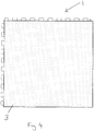
Fig. 4 is a top view of the tile according to the invention; -
Fig. 5 is a perspective view showing the interconnection of two tiles with the laminate removed for exemplary purposes; -
Fig. 6 is a perspective view showing two interconnected tiles, and -
Fig. 7 is a top view showing four interconnected tiles. - Referring to the drawings, there is shown a tile, indicated generally by the
reference numeral 1, comprising a base substrate, indicated generally by thereference numeral 2 and alaminate layer 3. Thesubstrate layer 2 has anupstanding edge 4 on atop surface 5 thereof, theedge 4 defining a rim at a perimeter of thesubstrate 2 for aligning thelaminate layer 3 on thetop surface 5. In the instance shown, therim 4 extends around the full perimeter of thetop surface 5 of thesubstrate 2 to form a nest on thesubstrate 2. Thelaminate layer 3 is bonded to thesubstrate layer 2 within the nest using an adhesive which may be applied to thelaminate 3 or thesubstrate 2. - The
substrate 2 comprises connecting means, indicated generally by thereference numeral 6, for engaging withconnecting means 6 of asubstrate layer 2 of afurther tile 1 to form an interconnected flooring system (seeFigs. 6 and7 ). Theconnecting means 6 comprises a plurality of protrudingtongues 7 andgrooves 8 at adjacent sides of thesubstrate 2. Thetop surface 5 of thesubstrate 2 extends over connecting means 6 on at least one side of thesubstrate layer 2. - As shown in
Fig. 5 , a protrudingtongue 7 of thesubstrate layer 2 of onetile 1 is engaged in agroove 8 of thesubstrate layer 2 of another tile 1' to connectadjacent tiles 1, 1' to form a flooring system 10 (seeFigs. 6 and7 ). InFig. 5 , for exemplary purposes thelaminate 3 of thetiles 1, 1' is shown removed so that theconnecting means 6 of thesubstrates 2, 2' can be clearly illustrated, and it should be understood that whentiles 1,1' are being interconnected they may be done so with or without thelaminate 3 bonded to thesubstrate layer 2. Any number oftiles 1 may be joined to form the requiredflooring system 10. - As shown, the portion of the
top surface 5 of thesubstrate layer 2 which extends over theconnecting means 6 oftile 1 will cover theconnecting means 6 of the adjacent tile 1' when the twotiles 1, 1' are interconnected. In this way engaging theconnecting means 6 ofadjacent tiles 1,1' aligns and positions theside edge 4 of thetile 1 with theside edge 4 of the further adjacent tile 1' in a side by side arrangement. This provides a grout effect consisting of theedges 4 of two interconnectedtiles substrate layer 2 may be made of any colour as required to provide the required colour for the grout effect. - There is also provided a method of forming a
tile 1 comprising the initial step of forming abase substrate 2 havingupstanding edges 4 which define arim 4 at a perimeter of the top surface of thesubstrate 2. An injection moulding tool may be fitted to an injection moulding machine an appropriately operated to form thebase substrate 2 and thebase substrate 2 removed from the machine when formed and allowed to dry. Such a tool is fitted to the machine between the machine plates and secured using mould clamps. Flexible PVC in any of various colours is then vacuum fed to a hopper of the moulding machine and gravity feed into a barrel of the machine where it is melted at between 180-190 degrees Celsius. The injection moulding machine is set to allow a screw inside the barrel to pick up sufficient melted material that is then injected through a nozzle of the barrel and into the closed mould at pre-set speeds and pressures. The mould remains closed for a pre-set time to allow cooling. The mould then opens and the substrate with moulded edges all around forming a receiving nest and interlocking keys is manually or automatically ejected from the mould. This moulded interlockingtile substrate 2 is then stacked on cooling racks for about 24 hours. It will be understood that the dimensions for the substrate may be moulded as required or as desired. - Next, an adhesive is applied to a bottom surface of a
laminate layer 3. Such a step may be performed by operating a roller coater machine to apply adhesive to the laminate layer. The adhesive may be a hot melt polyurethane adhesive or any other suitable adhesive and thelaminate layer 3 may comprise a PVC backing layer, a printed middle layer having a desired surface finish or effect for thetile 1, such as wood, porcelain, plastic etc, and a clear PVC top layer. Thelaminate layer 3 is sized as appropriate to sit in the nest on the substrate. - Next, the
laminate layer 3 is oriented as required and placed into the receiving nest of the substrate and aligned within therim 4 so that the bottom surface of thelaminate layer 3 sits on thetop surface 5 of thesubstrate 2. Pressure is then applied to thelaminate layer 3 on thesubstrate 2, such as by operating a nip-roller machine, so that thelaminate layer 3 is bonded to thesubstrate 2 to form thetile 1. The completedinterlocking tile 1 is then stacked flat on a cooling rack for a further 24 hours before packaging. - Aspects of the present invention have been described by way of example only and it should be appreciated that additions and/or modifications may be made thereto without departing from the appended claims.
Claims (10)
- A floor tile (1) comprising a base substrate (2) and a laminate layer (3), the base substrate (2) comprising:a top surface (5) and an upstanding edge (4) at a perimeter thereof defining a rim for aligning the laminate layer (3) on the top surface, andconnecting means (6) are located at each side of the base substrate (2) for connecting the floor tile (1) with an adjacent floor tile (1') to form a floor system of interconnected tiles (1, 1'),characterised in that the connecting means (6) comprises protruding tongues (7) and grooves (8) at each side of the base substrate (2), and the top surface (5) of the base substrate (2) extends fully over the protruding tongues (7) and grooves (8) on at least one side of the base substrate (2) andwhereby, when the tiles (1, 1') are connected, the top surface (5) of the base substrate (2) extends over to thereby fully cover protruding tongues (7) and grooves (8) forming a connecting means (6) at a side of the adjacent tile (1') to align and position the upstanding edge (4) of the base substrate (2) with an upstanding edge (4) on a top surface (5) of the adjacent tile (1') in a side by side arrangement to provide a grout effect comprising the upstanding edges (4) of the connected tiles (1, 1').
- A floor tile (1) as claimed in Claim 1, in which the laminate layer (3) is bonded to the substrate (2) using an adhesive.
- A floor tile (1) as claimed in any one of the preceding claims, in which the base substrate (2) is formed by injection moulding.
- A floor system comprising a plurality of floor tiles (1) according to any one of the preceding claims.
- A method of forming a floor tile (1) according to any one of Claims 1 to 3 comprising the steps of:forming the base substrate (2) ;applying an adhesive to a bottom surface of a laminate layer (3);aligning the laminate layer (3) within the rim such that the bottom surface of the laminate layer (3) sits on the top surface (5) of the substrate (2), andbonding the laminate layer (3) to the substrate (2) to form the tile (1).
- A method of forming a floor tile (1) as claimed in Claim 5, comprising the step of: operating an injection moulding machine to form the base substrate (2), whereby the injection moulding tool is manufactured with a machined recess on one half of the tool to create the rim which extends around the full perimeter of the top surface (5) of the substrate (2) and also a raised insert to create a nest area on the top surface (5) of the substrate (2) to receive the laminate layer (3).
- A method of forming a floor tile (1) as claimed in Claim 6, comprising the step of: removing the base substrate (2) from the injection moulding machine and allowing the base substrate (2) to cool.
- A method of forming a floor tile (1) as claimed in any one of Claims 5 to 7, the method comprising the step of: operating a roller coater machine to apply adhesive to the laminate layer (3).
- A method of forming a floor tile (1) as claimed in Claim 8, the method comprising the step of: applying pressure to the laminate layer (3) on the substrate (2).
- A method of forming a floor tile (1) as claimed in Claim 9, the method comprising the step of: operating a nip-roller machine to apply pressure to the laminate layer (3) on the base substrate (2).
Priority Applications (1)
| Application Number | Priority Date | Filing Date | Title |
|---|---|---|---|
| PL13707566T PL2812509T3 (en) | 2012-02-07 | 2013-02-07 | A floor tile |
Applications Claiming Priority (2)
| Application Number | Priority Date | Filing Date | Title |
|---|---|---|---|
| GB1202084.8A GB2495790B (en) | 2012-02-07 | 2012-02-07 | A floor tile |
| PCT/EP2013/052447 WO2013117653A2 (en) | 2012-02-07 | 2013-02-07 | A floor tile |
Publications (2)
| Publication Number | Publication Date |
|---|---|
| EP2812509A2 EP2812509A2 (en) | 2014-12-17 |
| EP2812509B1 true EP2812509B1 (en) | 2018-04-11 |
Family
ID=45896731
Family Applications (1)
| Application Number | Title | Priority Date | Filing Date |
|---|---|---|---|
| EP13707566.9A Active EP2812509B1 (en) | 2012-02-07 | 2013-02-07 | A floor tile |
Country Status (11)
| Country | Link |
|---|---|
| US (1) | US9771722B2 (en) |
| EP (1) | EP2812509B1 (en) |
| KR (2) | KR20170034442A (en) |
| CN (1) | CN104093922B (en) |
| AU (1) | AU2013218023B2 (en) |
| DK (1) | DK2812509T3 (en) |
| ES (1) | ES2676728T3 (en) |
| GB (1) | GB2495790B (en) |
| PL (1) | PL2812509T3 (en) |
| PT (1) | PT2812509T (en) |
| WO (1) | WO2013117653A2 (en) |
Cited By (1)
| Publication number | Priority date | Publication date | Assignee | Title |
|---|---|---|---|---|
| CZ309215B6 (en) * | 2021-03-23 | 2022-05-25 | Novotek Limited | Floor tiles |
Families Citing this family (25)
| Publication number | Priority date | Publication date | Assignee | Title |
|---|---|---|---|---|
| GB2541358B (en) | 2015-06-25 | 2017-12-13 | Evans Hurson Agnes | A floor tile |
| DE202016101245U1 (en) * | 2016-03-08 | 2016-04-14 | Selit Dämmtechnik GmbH | Underlay insulation for parquet and laminate flooring with side connectors and adhesive strips |
| KR101975949B1 (en) * | 2016-08-23 | 2019-05-07 | 정순업 | Prefabricated floor plate for saltern |
| US9938726B2 (en) | 2016-08-26 | 2018-04-10 | Quickstyle Industries Inc. | Densified foam core (DFC) tile with imitation grout line |
| US10544595B2 (en) | 2016-08-26 | 2020-01-28 | Quickstyle Industries Inc. | Tile with protected imitation grout line |
| US12392139B2 (en) | 2016-08-26 | 2025-08-19 | Quickstyle Industries, Inc. | Tile with imitation grout line |
| US10233656B2 (en) | 2016-08-26 | 2019-03-19 | Quickstyle Industries Inc. | Densified foam core (DFC) tile with imitation grout line |
| US10584498B2 (en) * | 2016-09-20 | 2020-03-10 | Tarkett Inc. | Floor panels |
| US10753100B2 (en) | 2017-08-11 | 2020-08-25 | Ecointeriors Corp. | Flooring panel equipped with quick-release adhesive sheet |
| US10914081B2 (en) | 2017-12-15 | 2021-02-09 | Wearwell, Llc | Interlocking modular mat with sponge insert |
| KR102074769B1 (en) * | 2018-02-22 | 2020-02-07 | 삼원액트 주식회사 | The metal interior material and interior material attachment structure |
| CN110886461B (en) * | 2018-09-10 | 2021-11-12 | 广东博智林机器人有限公司 | Floor chassis, raised floor system and laying method of system |
| TWM579195U (en) * | 2019-02-22 | 2019-06-11 | 鴻耀新技股份有限公司 | Assembled type plastic floor |
| USD895161S1 (en) * | 2019-04-12 | 2020-09-01 | Signature Systems Group Llc | Modular flooring tile |
| GB2584860B (en) * | 2019-06-18 | 2021-08-25 | Hurson Niall | Floor tile with waterproof connection |
| US11596253B2 (en) * | 2019-07-31 | 2023-03-07 | R&L Marketing & Sales, Inc. | Modular mat system |
| IT201900015117A1 (en) * | 2019-08-29 | 2021-03-01 | Flooring Ind Ltd Sarl | A floor covering element and a floor covering |
| CN110886459B (en) * | 2019-12-06 | 2024-07-12 | 浙江亚厦装饰股份有限公司 | Novel connection structure of floor tiles and application method |
| GB2593149B (en) * | 2020-03-05 | 2022-09-21 | R Tek Mfg Ltd | Tile manufacturing process |
| TW202144657A (en) * | 2020-05-25 | 2021-12-01 | 佳瑤企業股份有限公司 | Floor mat with moisture-proof effect comprising a base and a mat body that are not easy to produce peculiar smell and breed bacteria |
| KR102317642B1 (en) * | 2020-12-22 | 2021-10-26 | 삼원액트 주식회사 | Unit bracket, bracket |
| NL2028782B1 (en) | 2021-07-19 | 2023-01-25 | Jan Benninga Sievert | Method of laying a modular surface covering system and underlayment tile |
| CN216822705U (en) * | 2022-03-01 | 2022-06-28 | 苏州恒瑞达家用地垫有限公司 | Hidden concatenation ground mat |
| US12338648B2 (en) * | 2022-11-07 | 2025-06-24 | Sean Dehlinger | Modular tent floor assembly |
| US20240301707A1 (en) * | 2023-03-06 | 2024-09-12 | Cover Me, LLC | Hole cover system |
Citations (1)
| Publication number | Priority date | Publication date | Assignee | Title |
|---|---|---|---|---|
| EP2210995A1 (en) * | 2007-11-21 | 2010-07-28 | Alaves Montajes Y Realizaciones, SL | Tile for covering surfaces |
Family Cites Families (29)
| Publication number | Priority date | Publication date | Assignee | Title |
|---|---|---|---|---|
| US4287693A (en) * | 1980-03-26 | 1981-09-08 | Pawling Rubber Corporation | Interlocking rubber mat |
| FR2658225A1 (en) * | 1990-02-09 | 1991-08-16 | Soprema Sa | PLASTIC MATERIAL SLAB FOR THE COVERING OF BUILDING TERRACES. |
| US5212842A (en) * | 1992-09-17 | 1993-05-25 | Pi Consumer Products Corporation | Child's interlockable foam pad, foam pad structure and method |
| US5616389A (en) * | 1995-10-30 | 1997-04-01 | Blatz; Warren J. | Surface covering tile |
| AUPP137798A0 (en) * | 1998-01-16 | 1998-02-05 | Ezydeck Pty Ltd | Decking tile |
| US20060210762A1 (en) * | 2005-03-17 | 2006-09-21 | Tachauer Ernesto S | Rigid subtrates having molded projections, and methods of making the same |
| US6751912B2 (en) * | 2001-01-29 | 2004-06-22 | Spider Court, Inc. | Modular tile and tile flooring system |
| DK1323521T3 (en) | 2001-12-24 | 2008-11-24 | Forbo Giubiasco Sa | Hard cover plate |
| US20060062955A1 (en) * | 2003-08-14 | 2006-03-23 | Wen-Feng Liu | Self-adhesive laminate and method of making it |
| US7340865B2 (en) * | 2004-01-30 | 2008-03-11 | Selectech Inc. | Interlocking tile |
| US7748177B2 (en) * | 2004-02-25 | 2010-07-06 | Connor Sport Court International, Inc. | Modular tile with controlled deflection |
| US10390647B2 (en) * | 2004-04-08 | 2019-08-27 | Parallax Group International, Llc | Floor matting |
| US8397466B2 (en) * | 2004-10-06 | 2013-03-19 | Connor Sport Court International, Llc | Tile with multiple-level surface |
| US7610731B1 (en) * | 2005-01-10 | 2009-11-03 | Comc, Llc | Snap together floor structure |
| US7487622B2 (en) * | 2005-05-17 | 2009-02-10 | Wang Dennis H | Interlocking frame system for floor and wall structures |
| US20080127593A1 (en) * | 2006-07-14 | 2008-06-05 | Janesky Lawrence M | Moisture-resistant cover floor system for concrete floors |
| CA2596576C (en) * | 2007-08-08 | 2013-12-24 | Thomas Spencer Stanhope | Softwood-ceiling/hardwood-floor structure comprised of a single set of bonded boards |
| US20090047451A1 (en) * | 2007-08-17 | 2009-02-19 | Huss Philip C | Molded mat, and a method and a mold for making the mat |
| CA2704240A1 (en) * | 2007-10-30 | 2009-05-07 | Unika (Australia) Pty Limited | Tile tray |
| CN102251632A (en) | 2007-10-30 | 2011-11-23 | 优尼卡澳大利亚有限公司 | Ceramic tile bottom board |
| US8048506B2 (en) * | 2008-02-12 | 2011-11-01 | Ronald Wise | Carpet |
| US20110011020A1 (en) * | 2009-07-15 | 2011-01-20 | Chi-Feng Shen | Interlocking type plastic tile structure |
| US8535785B2 (en) * | 2009-10-30 | 2013-09-17 | Macneil Ip Llc | Floor tile |
| US20130111836A1 (en) * | 2009-10-30 | 2013-05-09 | Macneil Ip Llc | Injection molded floor tiles with drainage vents |
| US9339981B2 (en) * | 2009-10-30 | 2016-05-17 | Macneil Ip Llc | Method of making a floor tile with elastomer jacketed support members |
| US9181697B2 (en) * | 2009-10-30 | 2015-11-10 | Macneil Ip Llc | Floor tile having a latch and loop structure |
| US8539727B2 (en) * | 2009-11-19 | 2013-09-24 | Sun Wah Lui | Mechanically-held tile |
| US20110183101A1 (en) * | 2010-01-15 | 2011-07-28 | TPS TechnoPartner Samtronic GmbH | Floor covering and method for its production |
| US8806831B1 (en) * | 2010-03-10 | 2014-08-19 | Steven Ivan Dreyer | Interlocking floor tiles |
-
2012
- 2012-02-07 GB GB1202084.8A patent/GB2495790B/en active Active
-
2013
- 2013-02-07 EP EP13707566.9A patent/EP2812509B1/en active Active
- 2013-02-07 US US14/453,130 patent/US9771722B2/en active Active
- 2013-02-07 WO PCT/EP2013/052447 patent/WO2013117653A2/en not_active Ceased
- 2013-02-07 ES ES13707566.9T patent/ES2676728T3/en active Active
- 2013-02-07 KR KR1020177007201A patent/KR20170034442A/en not_active Ceased
- 2013-02-07 PT PT137075669T patent/PT2812509T/en unknown
- 2013-02-07 AU AU2013218023A patent/AU2013218023B2/en active Active
- 2013-02-07 CN CN201380008155.3A patent/CN104093922B/en active Active
- 2013-02-07 PL PL13707566T patent/PL2812509T3/en unknown
- 2013-02-07 KR KR1020147023720A patent/KR20140128352A/en not_active Ceased
- 2013-02-07 DK DK13707566.9T patent/DK2812509T3/en active
Patent Citations (1)
| Publication number | Priority date | Publication date | Assignee | Title |
|---|---|---|---|---|
| EP2210995A1 (en) * | 2007-11-21 | 2010-07-28 | Alaves Montajes Y Realizaciones, SL | Tile for covering surfaces |
Cited By (2)
| Publication number | Priority date | Publication date | Assignee | Title |
|---|---|---|---|---|
| CZ309215B6 (en) * | 2021-03-23 | 2022-05-25 | Novotek Limited | Floor tiles |
| EP4063583A1 (en) | 2021-03-23 | 2022-09-28 | Novotek Limited | Floor tile |
Also Published As
| Publication number | Publication date |
|---|---|
| AU2013218023B2 (en) | 2017-08-03 |
| GB201202084D0 (en) | 2012-03-21 |
| KR20170034442A (en) | 2017-03-28 |
| CN104093922A (en) | 2014-10-08 |
| ES2676728T3 (en) | 2018-07-24 |
| AU2013218023A1 (en) | 2014-09-11 |
| WO2013117653A2 (en) | 2013-08-15 |
| PL2812509T3 (en) | 2019-05-31 |
| US20150284965A1 (en) | 2015-10-08 |
| EP2812509A2 (en) | 2014-12-17 |
| WO2013117653A3 (en) | 2013-12-12 |
| CN104093922B (en) | 2017-10-31 |
| GB2495790B (en) | 2014-07-16 |
| KR20140128352A (en) | 2014-11-05 |
| PT2812509T (en) | 2018-07-11 |
| US9771722B2 (en) | 2017-09-26 |
| DK2812509T3 (en) | 2018-07-30 |
| GB2495790A (en) | 2013-04-24 |
Similar Documents
| Publication | Publication Date | Title |
|---|---|---|
| AU2013218023B2 (en) | A floor tile | |
| US10279560B2 (en) | Floor tile | |
| EP3931410B1 (en) | Floor tile with waterproof connection | |
| HK40064663A (en) | Floor tile with waterproof connection | |
| HK40064663B (en) | Floor tile with waterproof connection | |
| CA3167891C (en) | Tile manufacturing process | |
| HK40050581A (en) | Tile manufacturing process | |
| KR200433618Y1 (en) | Protective film support of the floor carpet |
Legal Events
| Date | Code | Title | Description |
|---|---|---|---|
| PUAI | Public reference made under article 153(3) epc to a published international application that has entered the european phase |
Free format text: ORIGINAL CODE: 0009012 |
|
| 17P | Request for examination filed |
Effective date: 20140818 |
|
| AK | Designated contracting states |
Kind code of ref document: A2 Designated state(s): AL AT BE BG CH CY CZ DE DK EE ES FI FR GB GR HR HU IE IS IT LI LT LU LV MC MK MT NL NO PL PT RO RS SE SI SK SM TR |
|
| AX | Request for extension of the european patent |
Extension state: BA ME |
|
| DAX | Request for extension of the european patent (deleted) | ||
| 17Q | First examination report despatched |
Effective date: 20160317 |
|
| STAA | Information on the status of an ep patent application or granted ep patent |
Free format text: STATUS: EXAMINATION IS IN PROGRESS |
|
| GRAP | Despatch of communication of intention to grant a patent |
Free format text: ORIGINAL CODE: EPIDOSNIGR1 |
|
| STAA | Information on the status of an ep patent application or granted ep patent |
Free format text: STATUS: GRANT OF PATENT IS INTENDED |
|
| INTG | Intention to grant announced |
Effective date: 20171108 |
|
| RIN1 | Information on inventor provided before grant (corrected) |
Inventor name: HURSON, RYAN PATRICK |
|
| GRAS | Grant fee paid |
Free format text: ORIGINAL CODE: EPIDOSNIGR3 |
|
| GRAA | (expected) grant |
Free format text: ORIGINAL CODE: 0009210 |
|
| STAA | Information on the status of an ep patent application or granted ep patent |
Free format text: STATUS: THE PATENT HAS BEEN GRANTED |
|
| AK | Designated contracting states |
Kind code of ref document: B1 Designated state(s): AL AT BE BG CH CY CZ DE DK EE ES FI FR GB GR HR HU IE IS IT LI LT LU LV MC MK MT NL NO PL PT RO RS SE SI SK SM TR |
|
| REG | Reference to a national code |
Ref country code: GB Ref legal event code: FG4D |
|
| REG | Reference to a national code |
Ref country code: CH Ref legal event code: EP |
|
| REG | Reference to a national code |
Ref country code: AT Ref legal event code: REF Ref document number: 988187 Country of ref document: AT Kind code of ref document: T Effective date: 20180415 |
|
| REG | Reference to a national code |
Ref country code: IE Ref legal event code: FG4D |
|
| REG | Reference to a national code |
Ref country code: DE Ref legal event code: R096 Ref document number: 602013035686 Country of ref document: DE |
|
| REG | Reference to a national code |
Ref country code: PT Ref legal event code: SC4A Ref document number: 2812509 Country of ref document: PT Date of ref document: 20180711 Kind code of ref document: T Free format text: AVAILABILITY OF NATIONAL TRANSLATION Effective date: 20180705 |
|
| REG | Reference to a national code |
Ref country code: ES Ref legal event code: FG2A Ref document number: 2676728 Country of ref document: ES Kind code of ref document: T3 Effective date: 20180724 |
|
| REG | Reference to a national code |
Ref country code: DK Ref legal event code: T3 Effective date: 20180719 |
|
| REG | Reference to a national code |
Ref country code: SE Ref legal event code: TRGR |
|
| REG | Reference to a national code |
Ref country code: NL Ref legal event code: FP |
|
| REG | Reference to a national code |
Ref country code: LT Ref legal event code: MG4D |
|
| REG | Reference to a national code |
Ref country code: CH Ref legal event code: NV Representative=s name: FREI PATENTANWALTSBUERO AG, CH |
|
| REG | Reference to a national code |
Ref country code: NO Ref legal event code: T2 Effective date: 20180411 |
|
| GRAT | Correction requested after decision to grant or after decision to maintain patent in amended form |
Free format text: ORIGINAL CODE: EPIDOSNCDEC |
|
| PG25 | Lapsed in a contracting state [announced via postgrant information from national office to epo] |
Ref country code: BG Free format text: LAPSE BECAUSE OF FAILURE TO SUBMIT A TRANSLATION OF THE DESCRIPTION OR TO PAY THE FEE WITHIN THE PRESCRIBED TIME-LIMIT Effective date: 20180711 Ref country code: LT Free format text: LAPSE BECAUSE OF FAILURE TO SUBMIT A TRANSLATION OF THE DESCRIPTION OR TO PAY THE FEE WITHIN THE PRESCRIBED TIME-LIMIT Effective date: 20180411 Ref country code: AL Free format text: LAPSE BECAUSE OF FAILURE TO SUBMIT A TRANSLATION OF THE DESCRIPTION OR TO PAY THE FEE WITHIN THE PRESCRIBED TIME-LIMIT Effective date: 20180411 |
|
| REG | Reference to a national code |
Ref country code: CH Ref legal event code: PCAR Free format text: NEW ADDRESS: POSTFACH, 8032 ZUERICH (CH) |
|
| PG25 | Lapsed in a contracting state [announced via postgrant information from national office to epo] |
Ref country code: LV Free format text: LAPSE BECAUSE OF FAILURE TO SUBMIT A TRANSLATION OF THE DESCRIPTION OR TO PAY THE FEE WITHIN THE PRESCRIBED TIME-LIMIT Effective date: 20180411 Ref country code: HR Free format text: LAPSE BECAUSE OF FAILURE TO SUBMIT A TRANSLATION OF THE DESCRIPTION OR TO PAY THE FEE WITHIN THE PRESCRIBED TIME-LIMIT Effective date: 20180411 Ref country code: RS Free format text: LAPSE BECAUSE OF FAILURE TO SUBMIT A TRANSLATION OF THE DESCRIPTION OR TO PAY THE FEE WITHIN THE PRESCRIBED TIME-LIMIT Effective date: 20180411 Ref country code: GR Free format text: LAPSE BECAUSE OF FAILURE TO SUBMIT A TRANSLATION OF THE DESCRIPTION OR TO PAY THE FEE WITHIN THE PRESCRIBED TIME-LIMIT Effective date: 20180712 |
|
| REG | Reference to a national code |
Ref country code: DE Ref legal event code: R097 Ref document number: 602013035686 Country of ref document: DE |
|
| PG25 | Lapsed in a contracting state [announced via postgrant information from national office to epo] |
Ref country code: EE Free format text: LAPSE BECAUSE OF FAILURE TO SUBMIT A TRANSLATION OF THE DESCRIPTION OR TO PAY THE FEE WITHIN THE PRESCRIBED TIME-LIMIT Effective date: 20180411 Ref country code: SK Free format text: LAPSE BECAUSE OF FAILURE TO SUBMIT A TRANSLATION OF THE DESCRIPTION OR TO PAY THE FEE WITHIN THE PRESCRIBED TIME-LIMIT Effective date: 20180411 Ref country code: RO Free format text: LAPSE BECAUSE OF FAILURE TO SUBMIT A TRANSLATION OF THE DESCRIPTION OR TO PAY THE FEE WITHIN THE PRESCRIBED TIME-LIMIT Effective date: 20180411 |
|
| PLBE | No opposition filed within time limit |
Free format text: ORIGINAL CODE: 0009261 |
|
| STAA | Information on the status of an ep patent application or granted ep patent |
Free format text: STATUS: NO OPPOSITION FILED WITHIN TIME LIMIT |
|
| PG25 | Lapsed in a contracting state [announced via postgrant information from national office to epo] |
Ref country code: SM Free format text: LAPSE BECAUSE OF FAILURE TO SUBMIT A TRANSLATION OF THE DESCRIPTION OR TO PAY THE FEE WITHIN THE PRESCRIBED TIME-LIMIT Effective date: 20180411 |
|
| 26N | No opposition filed |
Effective date: 20190114 |
|
| PG25 | Lapsed in a contracting state [announced via postgrant information from national office to epo] |
Ref country code: SI Free format text: LAPSE BECAUSE OF FAILURE TO SUBMIT A TRANSLATION OF THE DESCRIPTION OR TO PAY THE FEE WITHIN THE PRESCRIBED TIME-LIMIT Effective date: 20180411 |
|
| PG25 | Lapsed in a contracting state [announced via postgrant information from national office to epo] |
Ref country code: MC Free format text: LAPSE BECAUSE OF FAILURE TO SUBMIT A TRANSLATION OF THE DESCRIPTION OR TO PAY THE FEE WITHIN THE PRESCRIBED TIME-LIMIT Effective date: 20180411 |
|
| PG25 | Lapsed in a contracting state [announced via postgrant information from national office to epo] |
Ref country code: TR Free format text: LAPSE BECAUSE OF FAILURE TO SUBMIT A TRANSLATION OF THE DESCRIPTION OR TO PAY THE FEE WITHIN THE PRESCRIBED TIME-LIMIT Effective date: 20180411 |
|
| PG25 | Lapsed in a contracting state [announced via postgrant information from national office to epo] |
Ref country code: MT Free format text: LAPSE BECAUSE OF NON-PAYMENT OF DUE FEES Effective date: 20190207 |
|
| REG | Reference to a national code |
Ref country code: AT Ref legal event code: UEP Ref document number: 988187 Country of ref document: AT Kind code of ref document: T Effective date: 20180411 |
|
| PG25 | Lapsed in a contracting state [announced via postgrant information from national office to epo] |
Ref country code: CY Free format text: LAPSE BECAUSE OF FAILURE TO SUBMIT A TRANSLATION OF THE DESCRIPTION OR TO PAY THE FEE WITHIN THE PRESCRIBED TIME-LIMIT Effective date: 20180411 |
|
| PG25 | Lapsed in a contracting state [announced via postgrant information from national office to epo] |
Ref country code: IS Free format text: LAPSE BECAUSE OF FAILURE TO SUBMIT A TRANSLATION OF THE DESCRIPTION OR TO PAY THE FEE WITHIN THE PRESCRIBED TIME-LIMIT Effective date: 20180811 |
|
| PG25 | Lapsed in a contracting state [announced via postgrant information from national office to epo] |
Ref country code: HU Free format text: LAPSE BECAUSE OF FAILURE TO SUBMIT A TRANSLATION OF THE DESCRIPTION OR TO PAY THE FEE WITHIN THE PRESCRIBED TIME-LIMIT; INVALID AB INITIO Effective date: 20130207 |
|
| PG25 | Lapsed in a contracting state [announced via postgrant information from national office to epo] |
Ref country code: MK Free format text: LAPSE BECAUSE OF FAILURE TO SUBMIT A TRANSLATION OF THE DESCRIPTION OR TO PAY THE FEE WITHIN THE PRESCRIBED TIME-LIMIT Effective date: 20180411 |
|
| REG | Reference to a national code |
Ref country code: GB Ref legal event code: 732E Free format text: REGISTERED BETWEEN 20230427 AND 20230503 |
|
| P01 | Opt-out of the competence of the unified patent court (upc) registered |
Effective date: 20230509 |
|
| REG | Reference to a national code |
Ref country code: DE Ref legal event code: R081 Ref document number: 602013035686 Country of ref document: DE Owner name: R-TEK MANUFACTURING LTD., GB Free format text: FORMER OWNERS: ATKINS, MICHAEL PAUL NICHOLAS, PULLOXHILL, BEDFORDSHIRE, GB; HURSON, RYAN PATRICK, WARRENPOINT, COUNTY DOWN, GB; VAN LEUSDEN, EVERARDUS JOHANNES MARIA, MAARSSEN, NL Ref country code: NO Ref legal event code: CHAD Owner name: R-TEK MANUFACTURING LTD, GB |
|
| REG | Reference to a national code |
Ref country code: AT Ref legal event code: PC Ref document number: 988187 Country of ref document: AT Kind code of ref document: T Owner name: R-TEK MANUFACTURING LTD, GB Effective date: 20230704 |
|
| REG | Reference to a national code |
Ref country code: FI Ref legal event code: PCE Owner name: R-TEK MANUFACTURING LTD |
|
| REG | Reference to a national code |
Ref country code: BE Ref legal event code: PD Owner name: R-TEK MANUFACTURING LTD; GB Free format text: DETAILS ASSIGNMENT: CHANGE OF OWNER(S), ASSIGNMENT; FORMER OWNER NAME: VAN LEUSDEN, EVERARDUS JOHANNES MARIA Effective date: 20230712 |
|
| REG | Reference to a national code |
Ref country code: NL Ref legal event code: PD Owner name: R-TEK MANUFACTURING LTD; GB Free format text: DETAILS ASSIGNMENT: CHANGE OF OWNER(S), ASSIGNMENT; FORMER OWNER NAME: VAN LEUSDEN, EVERARDUS JOHANNES MARIA Effective date: 20231013 |
|
| REG | Reference to a national code |
Ref country code: ES Ref legal event code: PC2A Owner name: R-TEK MANUFACTURING LTD Effective date: 20240603 |
|
| PGFP | Annual fee paid to national office [announced via postgrant information from national office to epo] |
Ref country code: LU Payment date: 20260127 Year of fee payment: 14 Ref country code: NL Payment date: 20260127 Year of fee payment: 14 |
|
| REG | Reference to a national code |
Ref country code: CH Ref legal event code: U11 Free format text: ST27 STATUS EVENT CODE: U-0-0-U10-U11 (AS PROVIDED BY THE NATIONAL OFFICE) Effective date: 20260301 |
|
| PGFP | Annual fee paid to national office [announced via postgrant information from national office to epo] |
Ref country code: SE Payment date: 20260219 Year of fee payment: 14 |
|
| PGFP | Annual fee paid to national office [announced via postgrant information from national office to epo] |
Ref country code: GB Payment date: 20260219 Year of fee payment: 14 |
|
| PGFP | Annual fee paid to national office [announced via postgrant information from national office to epo] |
Ref country code: ES Payment date: 20260309 Year of fee payment: 14 |
|
| PGFP | Annual fee paid to national office [announced via postgrant information from national office to epo] |
Ref country code: NO Payment date: 20260127 Year of fee payment: 14 Ref country code: DK Payment date: 20260129 Year of fee payment: 14 Ref country code: IE Payment date: 20260121 Year of fee payment: 14 Ref country code: DE Payment date: 20260206 Year of fee payment: 14 |
|
| PGFP | Annual fee paid to national office [announced via postgrant information from national office to epo] |
Ref country code: AT Payment date: 20260120 Year of fee payment: 14 |
|
| PGFP | Annual fee paid to national office [announced via postgrant information from national office to epo] |
Ref country code: BE Payment date: 20260223 Year of fee payment: 14 Ref country code: FI Payment date: 20260120 Year of fee payment: 14 Ref country code: IT Payment date: 20260210 Year of fee payment: 14 |
|
| PGFP | Annual fee paid to national office [announced via postgrant information from national office to epo] |
Ref country code: FR Payment date: 20260227 Year of fee payment: 14 |
|
| PGFP | Annual fee paid to national office [announced via postgrant information from national office to epo] |
Ref country code: CH Payment date: 20260301 Year of fee payment: 14 Ref country code: PT Payment date: 20260119 Year of fee payment: 14 Ref country code: CZ Payment date: 20260130 Year of fee payment: 14 |
|
| PGFP | Annual fee paid to national office [announced via postgrant information from national office to epo] |
Ref country code: PL Payment date: 20260119 Year of fee payment: 14 |