EP2812469B1 - Modified polylactic acid fibers - Google Patents
Modified polylactic acid fibers Download PDFInfo
- Publication number
- EP2812469B1 EP2812469B1 EP13746953.2A EP13746953A EP2812469B1 EP 2812469 B1 EP2812469 B1 EP 2812469B1 EP 13746953 A EP13746953 A EP 13746953A EP 2812469 B1 EP2812469 B1 EP 2812469B1
- Authority
- EP
- European Patent Office
- Prior art keywords
- fibers
- fiber
- polylactic acid
- component
- mpm
- Prior art date
- Legal status (The legal status is an assumption and is not a legal conclusion. Google has not performed a legal analysis and makes no representation as to the accuracy of the status listed.)
- Not-in-force
Links
Images


Classifications
-
- D—TEXTILES; PAPER
- D04—BRAIDING; LACE-MAKING; KNITTING; TRIMMINGS; NON-WOVEN FABRICS
- D04H—MAKING TEXTILE FABRICS, e.g. FROM FIBRES OR FILAMENTARY MATERIAL; FABRICS MADE BY SUCH PROCESSES OR APPARATUS, e.g. FELTS, NON-WOVEN FABRICS; COTTON-WOOL; WADDING ; NON-WOVEN FABRICS FROM STAPLE FIBRES, FILAMENTS OR YARNS, BONDED WITH AT LEAST ONE WEB-LIKE MATERIAL DURING THEIR CONSOLIDATION
- D04H1/00—Non-woven fabrics formed wholly or mainly of staple fibres or like relatively short fibres
- D04H1/40—Non-woven fabrics formed wholly or mainly of staple fibres or like relatively short fibres from fleeces or layers composed of fibres without existing or potential cohesive properties
- D04H1/42—Non-woven fabrics formed wholly or mainly of staple fibres or like relatively short fibres from fleeces or layers composed of fibres without existing or potential cohesive properties characterised by the use of certain kinds of fibres insofar as this use has no preponderant influence on the consolidation of the fleece
- D04H1/4326—Condensation or reaction polymers
-
- D—TEXTILES; PAPER
- D04—BRAIDING; LACE-MAKING; KNITTING; TRIMMINGS; NON-WOVEN FABRICS
- D04H—MAKING TEXTILE FABRICS, e.g. FROM FIBRES OR FILAMENTARY MATERIAL; FABRICS MADE BY SUCH PROCESSES OR APPARATUS, e.g. FELTS, NON-WOVEN FABRICS; COTTON-WOOL; WADDING ; NON-WOVEN FABRICS FROM STAPLE FIBRES, FILAMENTS OR YARNS, BONDED WITH AT LEAST ONE WEB-LIKE MATERIAL DURING THEIR CONSOLIDATION
- D04H1/00—Non-woven fabrics formed wholly or mainly of staple fibres or like relatively short fibres
- D04H1/40—Non-woven fabrics formed wholly or mainly of staple fibres or like relatively short fibres from fleeces or layers composed of fibres without existing or potential cohesive properties
- D04H1/42—Non-woven fabrics formed wholly or mainly of staple fibres or like relatively short fibres from fleeces or layers composed of fibres without existing or potential cohesive properties characterised by the use of certain kinds of fibres insofar as this use has no preponderant influence on the consolidation of the fleece
- D04H1/4382—Stretched reticular film fibres; Composite fibres; Mixed fibres; Ultrafine fibres; Fibres for artificial leather
- D04H1/43838—Ultrafine fibres, e.g. microfibres
-
- D—TEXTILES; PAPER
- D01—NATURAL OR MAN-MADE THREADS OR FIBRES; SPINNING
- D01F—CHEMICAL FEATURES IN THE MANUFACTURE OF ARTIFICIAL FILAMENTS, THREADS, FIBRES, BRISTLES OR RIBBONS; APPARATUS SPECIALLY ADAPTED FOR THE MANUFACTURE OF CARBON FILAMENTS
- D01F6/00—Monocomponent artificial filaments or the like of synthetic polymers; Manufacture thereof
- D01F6/88—Monocomponent artificial filaments or the like of synthetic polymers; Manufacture thereof from mixtures of polycondensation products as major constituent with other polymers or low-molecular-weight compounds
- D01F6/92—Monocomponent artificial filaments or the like of synthetic polymers; Manufacture thereof from mixtures of polycondensation products as major constituent with other polymers or low-molecular-weight compounds of polyesters
-
- D—TEXTILES; PAPER
- D01—NATURAL OR MAN-MADE THREADS OR FIBRES; SPINNING
- D01F—CHEMICAL FEATURES IN THE MANUFACTURE OF ARTIFICIAL FILAMENTS, THREADS, FIBRES, BRISTLES OR RIBBONS; APPARATUS SPECIALLY ADAPTED FOR THE MANUFACTURE OF CARBON FILAMENTS
- D01F8/00—Conjugated, i.e. bi- or multicomponent, artificial filaments or the like; Manufacture thereof
- D01F8/04—Conjugated, i.e. bi- or multicomponent, artificial filaments or the like; Manufacture thereof from synthetic polymers
- D01F8/14—Conjugated, i.e. bi- or multicomponent, artificial filaments or the like; Manufacture thereof from synthetic polymers with at least one polyester as constituent
-
- D—TEXTILES; PAPER
- D04—BRAIDING; LACE-MAKING; KNITTING; TRIMMINGS; NON-WOVEN FABRICS
- D04H—MAKING TEXTILE FABRICS, e.g. FROM FIBRES OR FILAMENTARY MATERIAL; FABRICS MADE BY SUCH PROCESSES OR APPARATUS, e.g. FELTS, NON-WOVEN FABRICS; COTTON-WOOL; WADDING ; NON-WOVEN FABRICS FROM STAPLE FIBRES, FILAMENTS OR YARNS, BONDED WITH AT LEAST ONE WEB-LIKE MATERIAL DURING THEIR CONSOLIDATION
- D04H1/00—Non-woven fabrics formed wholly or mainly of staple fibres or like relatively short fibres
- D04H1/40—Non-woven fabrics formed wholly or mainly of staple fibres or like relatively short fibres from fleeces or layers composed of fibres without existing or potential cohesive properties
- D04H1/42—Non-woven fabrics formed wholly or mainly of staple fibres or like relatively short fibres from fleeces or layers composed of fibres without existing or potential cohesive properties characterised by the use of certain kinds of fibres insofar as this use has no preponderant influence on the consolidation of the fleece
- D04H1/4382—Stretched reticular film fibres; Composite fibres; Mixed fibres; Ultrafine fibres; Fibres for artificial leather
- D04H1/43825—Composite fibres
- D04H1/43828—Composite fibres sheath-core
-
- D—TEXTILES; PAPER
- D04—BRAIDING; LACE-MAKING; KNITTING; TRIMMINGS; NON-WOVEN FABRICS
- D04H—MAKING TEXTILE FABRICS, e.g. FROM FIBRES OR FILAMENTARY MATERIAL; FABRICS MADE BY SUCH PROCESSES OR APPARATUS, e.g. FELTS, NON-WOVEN FABRICS; COTTON-WOOL; WADDING ; NON-WOVEN FABRICS FROM STAPLE FIBRES, FILAMENTS OR YARNS, BONDED WITH AT LEAST ONE WEB-LIKE MATERIAL DURING THEIR CONSOLIDATION
- D04H3/00—Non-woven fabrics formed wholly or mainly of yarns or like filamentary material of substantial length
- D04H3/02—Non-woven fabrics formed wholly or mainly of yarns or like filamentary material of substantial length characterised by the method of forming fleeces or layers, e.g. reorientation of yarns or filaments
-
- D—TEXTILES; PAPER
- D01—NATURAL OR MAN-MADE THREADS OR FIBRES; SPINNING
- D01D—MECHANICAL METHODS OR APPARATUS IN THE MANUFACTURE OF ARTIFICIAL FILAMENTS, THREADS, FIBRES, BRISTLES OR RIBBONS
- D01D5/00—Formation of filaments, threads, or the like
- D01D5/28—Formation of filaments, threads, or the like while mixing different spinning solutions or melts during the spinning operation; Spinnerette packs therefor
- D01D5/30—Conjugate filaments; Spinnerette packs therefor
- D01D5/34—Core-skin structure; Spinnerette packs therefor
-
- D—TEXTILES; PAPER
- D01—NATURAL OR MAN-MADE THREADS OR FIBRES; SPINNING
- D01F—CHEMICAL FEATURES IN THE MANUFACTURE OF ARTIFICIAL FILAMENTS, THREADS, FIBRES, BRISTLES OR RIBBONS; APPARATUS SPECIALLY ADAPTED FOR THE MANUFACTURE OF CARBON FILAMENTS
- D01F1/00—General methods for the manufacture of artificial filaments or the like
- D01F1/02—Addition of substances to the spinning solution or to the melt
- D01F1/10—Other agents for modifying properties
-
- D—TEXTILES; PAPER
- D01—NATURAL OR MAN-MADE THREADS OR FIBRES; SPINNING
- D01F—CHEMICAL FEATURES IN THE MANUFACTURE OF ARTIFICIAL FILAMENTS, THREADS, FIBRES, BRISTLES OR RIBBONS; APPARATUS SPECIALLY ADAPTED FOR THE MANUFACTURE OF CARBON FILAMENTS
- D01F8/00—Conjugated, i.e. bi- or multicomponent, artificial filaments or the like; Manufacture thereof
- D01F8/04—Conjugated, i.e. bi- or multicomponent, artificial filaments or the like; Manufacture thereof from synthetic polymers
- D01F8/06—Conjugated, i.e. bi- or multicomponent, artificial filaments or the like; Manufacture thereof from synthetic polymers with at least one polyolefin as constituent
-
- D—TEXTILES; PAPER
- D04—BRAIDING; LACE-MAKING; KNITTING; TRIMMINGS; NON-WOVEN FABRICS
- D04H—MAKING TEXTILE FABRICS, e.g. FROM FIBRES OR FILAMENTARY MATERIAL; FABRICS MADE BY SUCH PROCESSES OR APPARATUS, e.g. FELTS, NON-WOVEN FABRICS; COTTON-WOOL; WADDING ; NON-WOVEN FABRICS FROM STAPLE FIBRES, FILAMENTS OR YARNS, BONDED WITH AT LEAST ONE WEB-LIKE MATERIAL DURING THEIR CONSOLIDATION
- D04H1/00—Non-woven fabrics formed wholly or mainly of staple fibres or like relatively short fibres
- D04H1/40—Non-woven fabrics formed wholly or mainly of staple fibres or like relatively short fibres from fleeces or layers composed of fibres without existing or potential cohesive properties
- D04H1/42—Non-woven fabrics formed wholly or mainly of staple fibres or like relatively short fibres from fleeces or layers composed of fibres without existing or potential cohesive properties characterised by the use of certain kinds of fibres insofar as this use has no preponderant influence on the consolidation of the fleece
- D04H1/4382—Stretched reticular film fibres; Composite fibres; Mixed fibres; Ultrafine fibres; Fibres for artificial leather
-
- D—TEXTILES; PAPER
- D04—BRAIDING; LACE-MAKING; KNITTING; TRIMMINGS; NON-WOVEN FABRICS
- D04H—MAKING TEXTILE FABRICS, e.g. FROM FIBRES OR FILAMENTARY MATERIAL; FABRICS MADE BY SUCH PROCESSES OR APPARATUS, e.g. FELTS, NON-WOVEN FABRICS; COTTON-WOOL; WADDING ; NON-WOVEN FABRICS FROM STAPLE FIBRES, FILAMENTS OR YARNS, BONDED WITH AT LEAST ONE WEB-LIKE MATERIAL DURING THEIR CONSOLIDATION
- D04H3/00—Non-woven fabrics formed wholly or mainly of yarns or like filamentary material of substantial length
- D04H3/005—Synthetic yarns or filaments
- D04H3/009—Condensation or reaction polymers
- D04H3/011—Polyesters
Definitions
- PLA polylactic acid
- PLA nonwoven webs generally possess a low bond flexibility and high roughness due to the high glass transition temperature and slow crystallization rate of polylactic acid.
- thermally bonded PLA nonwoven webs often exhibit low elongations that are not acceptable in certain applications, such as in an absorbent article.
- polylactic acid may withstand high draw ratios, it requires high levels of draw energy to achieve the crystallization needed to overcome heat shrinkage.
- plasticizers have been employed in an attempt to reduce the glass transition temperature and improve bonding and softness.
- One common plasticizer is polyethylene glycol.
- polyethylene glycol tends to phase separate from polylactic acid during aging, especially in high humidity and elevated temperature environment, which deteriorates the mechanical properties of the resulting fibers over time.
- the addition of plasticizers also causes other problems, such as degradation in melt spinning, and a reduction in melt strength and drawability.
- a method for forming a multi-component fiber comprises blending a polylactic acid, polymeric toughening additive, and polyepoxide modifier to form a thermoplastic composition, and thereafter extruding the thermoplastic composition through a die to form a fiber.
- the fiber contains a core component surrounded by a sheath component, and the polylactic acid constitutes about 50 wt.% or more of the polymer content of the core component and the polymeric toughening additive constitutes about 50 wt.% or more of the polymer content of the sheath component.
- a multi-component fiber contains a core component surrounded by a sheath component.
- Polylactic acid constitutes about 50 wt.% or more of the polymer content of the core component and a polymeric toughening additive constitutes about 50 wt.% or more of the polymer content of the sheath component.
- the polylactic acid in the core component and the polymeric toughening additive in the sheath component are derived from a single thermoplastic composition in which the polylactic acid is blended with the polymeric toughening additive.
- biodegradable or “biodegradable polymer” generally refers to a material that degrades from the action of naturally occurring microorganisms, such as bacteria, fungi, and algae; environmental heat; moisture; or other environmental factors.
- the biodegradability of a material may be determined using ASTM Test Method 5338.92.
- fibers refer to elongated extrudates formed by passing a polymer through a forming orifice such as a die. Unless noted otherwise, the term “fibers” includes both discontinuous fibers having a definite length and substantially continuous filaments. Substantially filaments may, for instance, have a length much greater than their diameter, such as a length to diameter ratio (“aspect ratio") greater than about 15,000 to 1, and in some cases, greater than about 50,000 to 1.
- aspect ratio length to diameter ratio
- nonwoven web refers to a web having a structure of individual fibers that are randomly interlaid, not in an identifiable manner as in a knitted fabric.
- Nonwoven webs include, for example, meltblown webs, spunbond webs, carded webs, wet-laid webs, airlaid webs, coform webs, hydraulically entangled webs, etc.
- the basis weight of the nonwoven web may generally vary, but is typically from about 5 grams per square meter ("gsm") to 200 gsm, in some embodiments from about 10 gsm to about 150 gsm, and in some embodiments, from about 15 gsm to about 100 gsm.
- meltblown web or layer generally refers to a nonwoven web that is formed by a process in which a molten thermoplastic material is extruded through a plurality of fine, usually circular, die capillaries as molten fibers into converging high velocity gas (e.g., air) streams that attenuate the fibers of molten thermoplastic material to reduce their diameter, which may be to microfiber diameter. Thereafter, the meltblown fibers are carried by the high velocity gas stream and are deposited on a collecting surface to form a web of randomly dispersed meltblown fibers.
- high velocity gas e.g., air
- Meltblown fibers may be substantially continuous or discontinuous, and are generally tacky when deposited onto a collecting surface.
- spunbond web or layer generally refers to a nonwoven web containing small diameter substantially continuous filaments.
- the filaments are formed by extruding a molten thermoplastic material from a plurality of fine, usually circular, capillaries of a spinnerette with the diameter of the extruded filaments then being rapidly reduced as by, for example, eductive drawing and/or other well-known spunbonding mechanisms.
- the production of spunbond webs is described and illustrated, for example, in U.S. Patent Nos. 4,340,563 to Appel, et al. , 3,692,618 to Dorschner, et al. , 3,802,817 to Matsuki, et al.
- Spunbond filaments are generally not tacky when they are deposited onto a collecting surface. Spunbond filaments may sometimes have diameters less than about 40 micrometers, and are often between about 5 to about 20 micrometers.
- melt flow rate is the weight of a polymer (in grams) forced through an extrusion rheometer orifice (0.0825-inch diameter) when subjected to a load of 2160 grams in 10 minutes, typically at 190°C or 230°C. Unless otherwise indicated, melt flow rate is measured in accordance with ASTM Test Method D1239 with a Tinius Olsen Extrusion Plastometer.
- the melting temperature and glass transition temperature may be determined by differential scanning calorimetry (DSC).
- the differential scanning calorimeter may be a DSC Q100 Differential Scanning Calorimeter, which was outfitted with a liquid nitrogen cooling accessory and with a UNIVERSAL ANALYSIS 2000 (version 4.6.6) analysis software program, both of which are available from T.A. Instruments Inc. of New Castle, Delaware.
- tweezers or other tools are used to avoid directly handling the samples.
- the samples are placed into an aluminum pan and weighed to an accuracy of 0.01 milligram on an analytical balance. A lid is crimped over the material sample onto the pan.
- the resin pellets are placed directly in the weighing pan, and the fibers are cut to accommodate placement on the weighing pan and covering by the lid.
- the differential scanning calorimeter is calibrated using an indium metal standard and a baseline correction is performed, as described in the operating manual for the differential scanning calorimeter.
- a material sample is placed into the test chamber of the differential scanning calorimeter for testing, and an empty pan is used as a reference. All testing is run with a 55-cubic centimeter per minute nitrogen (industrial grade) purge on the test chamber.
- the heating and cooling program is a 2-cycle test that began with an equilibration of the chamber to -30°C, followed by a first heating period at a heating rate of 10°C per minute to a temperature of 200°C, followed by equilibration of the sample at 200°C for 3 minutes, followed by a first cooling period at a cooling rate of 10°C per minute to a temperature of -30°C, followed by equilibration of the sample at - 30°C for 3 minutes, and then a second heating period at a heating rate of 10°C per minute to a temperature of 200°C.
- the heating and cooling program is a 1-cycle test that began with an equilibration of the chamber to -25°C, followed by a heating period at a heating rate of 10°C per minute to a temperature of 200°C, followed by equilibration of the sample at 200°C for 3 minutes, and then a cooling period at a cooling rate of 10°C per minute to a temperature of -30°C. All testing is run with a 55-cubic centimeter per minute nitrogen (industrial grade) purge on the test chamber.
- the results are evaluated using the UNIVERSAL ANALYSIS 2000 analysis software program, which identified and quantified the glass transition temperature (Tg) of inflection, the endothermic and exothermic peaks, and the areas under the peaks on the DSC plots.
- Tg glass transition temperature
- the glass transition temperature is identified as the region on the plot-line where a distinct change in slope occurred, and the melting temperature is determined using an automatic inflection calculation.
- Individual fiber specimens are shortened (e.g., cut with scissors) to 38 millimeters in length, and placed separately on a black velvet cloth. 10 to 15 fiber specimens are collected in this manner.
- the fiber specimens are then mounted in a substantially straight condition on a rectangular paper frame having external dimension of 51 millimeters x 51 millimeters and internal dimension of 25 millimeters x 25 millimeters.
- the ends of each fiber specimen are operatively attached to the frame by carefully securing the fiber ends to the sides of the frame with adhesive tape.
- Each fiber specimen is then measured for its external, relatively shorter, cross-fiber dimension employing a conventional laboratory microscope, which has been properly calibrated and set at 40X magnification. This cross-fiber dimension is recorded as the diameter of the individual fiber specimen.
- the frame helps to mount the ends of the sample fiber specimens in the upper and lower grips of a constant rate of extension type tensile tester in a manner that avoids excessive damage to the fiber specimens.
- a constant rate of extension type of tensile tester and an appropriate load cell are employed for the testing.
- the load cell is chosen (e.g., 1 ON) so that the test value falls within 10-90% of the full scale load.
- the tensile tester i.e., MTS SYNERGY 200
- load cell are obtained from MTS Systems Corporation of Eden Prairie, Michigan.
- the fiber specimens in the frame assembly are then mounted between the grips of the tensile tester such that the ends of the fibers are operatively held by the grips of the tensile tester. Then, the sides of the paper frame that extend parallel to the fiber length are cut or otherwise separated so that the tensile tester applies the test force only to the fibers.
- the fibers are then subjected to a pull test at a pull rate and grip speed of 12 inches per minute.
- the resulting data is analyzed using a TESTWORKS 4 software program from the MTS Corporation with the following test settings: Calculation Inputs Test Inputs Break mark drop 50% Break sensitivity 90% Break marker elongation 0.1 in Break threshold 10 g f Nominal gage length 1 in Data Acq. Rate 10 Hz Slack pre-load 1 lb f Denier length 9000 m Slope segment length 20% Density 1.25 g/cm 3 Yield offset 0.20% Initial speed 12 in/min Yield segment length 2% Secondary speed 2 in/min
- the tenacity values are expressed in terms of gram-force per denier. Peak elongation (% strain at break) is also measured.
- Moisture content may be determined using an Arizona Instruments Computrac Vapor Pro moisture analyzer (Model No. 3100) in substantial accordance with ASTM D 7191-05, which is incorporated herein in its entirety by reference thereto for all purposes.
- the test temperature ( ⁇ X2.1.2) may be 130°C
- the sample size ( ⁇ X2.1.1) may be 2 to 4 grams
- the vial purge time ( ⁇ X2.1.4) may be 30 seconds.
- the ending criteria ( ⁇ X2.1.3) may be defined as a "prediction" mode, which means that the test is ended when the built-in programmed criteria (which mathematically calculates the end point moisture content) is satisfied.
- the present invention is directed to a multi-component fiber that includes a core component surrounded by a distinct sheath component, which can be continuous or discontinuous (e.g., fragmented) along the surface of the fiber.
- the core component is formed primarily from polylactic acid and the sheath component is formed primarily from a polymeric toughening additive.
- polylactic acid may constitute about 50 wt.% or more, in some embodiments from about 75 wt.% or more, and in some embodiments, from about 90 wt.% to 100 wt.% of the polymer content of the core component
- the polymeric toughening additive may constitute about 50 wt.% or more, in some embodiments from about 75 wt.% or more, and in some embodiments, from about 90 wt.% to 100 wt.% of the polymer content of the sheath component.
- the relative thickness of the sheath component is typically small.
- the sheath component typically constitutes only from about 0.5% to about 25%, in some embodiments from about 1% to about 20%, and in some embodiments, from about 2% to about 15% of the diameter of the fiber, while the core component typically constitutes from about 75% to about 99.5%, in some embodiments from about 80% to about 99%, and in some embodiments, from about 85% to about 98% of the diameter of the fiber.
- the thickness of the sheath component may, for instance, be from about 100 nanometers to about 5 micrometers, in some embodiments from about 200 nanometers to about 4 micrometers, and in some embodiments, from about 500 nanometers to about 2 micrometers.
- the sheath/core configuration of the fiber of the present invention may provide a variety of different benefits to the resulting fiber.
- the polymeric toughening additive can help increase the ability of the fiber to absorb energy that arises from stresses imparted during fiber drawing, which increases the overall toughness and strength of the fibers.
- the presence of the toughening additive in the sheath component can enhance the degree of bonding to other fibers (the same or different), such as when employed in a nonwoven web material.
- the sheath component can also provide screw lubrication and reduce the level of torque needed during fiber extrusion.
- the sheath/core configuration may be formed from a thermoplastic composition in which the polylactic acid and polymeric toughening additive are blended together.
- the use of a blended thermoplastic composition can reduce costs and manufacturing complexity. Without intending to be limited by theory, the present inventors believe that the use of a blended thermoplastic composition to form the sheath/core configuration is possible due to the unique manner in which the polymeric components are dispersed within the blend, and the manner in which the melt blending and extrusion conditions are controlled so that the polymeric toughening additive is able to migrate to the surface of the core.
- a polyepoxide modifier is employed in the composition that acts as a compatibilizer to enhance the homogeneity of the dispersion, and thus increase the likelihood that the polymeric toughening additive can migrate to the surface and form a distinct zone or layer over the polylactic acid core.
- the polyepoxide modifier also has an additional benefit in that it can react with the polylactic acid, thereby improving its melt strength and stability during fiber spinning without significantly reducing glass transition temperature.
- Polylactic acid may generally be derived from monomer units of any isomer of lactic acid, such as levorotory-lactic acid (“L-lactic acid”), dextrorotatory-lactic acid (“D-lactic acid”), meso-lactic acid, or mixtures thereof. Monomer units may also be formed from anhydrides of any isomer of lactic acid, including L-lactide, D-lactide, meso-lactide, or mixtures thereof. Cyclic dimers of such lactic acids and/or lactides may also be employed. Any known polymerization method, such as polycondensation or ring-opening polymerization, may be used to polymerize lactic acid.
- L-lactic acid levorotory-lactic acid
- D-lactic acid dextrorotatory-lactic acid
- meso-lactic acid or mixtures thereof.
- Monomer units may also be formed from anhydrides of any isomer of lactic acid, including L-lactide, D-lactide, meso-lact
- a small amount of a chain-extending agent may also be employed.
- the polylactic acid may be a homopolymer or a copolymer, such as one that contains monomer units derived from L-lactic acid and monomer units derived from D-lactic acid.
- the rate of content of one of the monomer unit derived from L-lactic acid and the monomer unit derived from D-lactic acid is preferably about 85 mole% or more, in some embodiments about 90 mole% or more, and in some embodiments, about 95 mole% or more.
- polylactic acids each having a different ratio between the monomer unit derived from L-lactic acid and the monomer unit derived from D-lactic acid, may be blended at an arbitrary percentage.
- polylactic acid may also be blended with other types of polymers (e.g., polyolefins, polyesters, etc.) to provided a variety of different of benefits, such as processing, fiber formation, etc.
- the polylactic acid has the following general structure:
- a suitable polylactic acid polymer that may be used in the present invention is commercially available from Biomer, Inc. of Krailling, Germany) under the name BIOMERTM L9000.
- Other suitable polylactic acid polymers are commercially available from Natureworks LLC of Minnetonka, Minnesota (NATUREWORKS®) or Mitsui Chemical (LACEATM).
- Still other suitable polylactic acids may be described in U.S. Patent Nos. 4,797,468 ; 5,470,944 ; 5,770,682 ; 5,821,327 ; 5,880,254 ; and 6,326,458 , which are incorporated herein in their entirety by reference thereto for all purposes.
- the polylactic acid typically has a melting point of from about 140°C to about 260°C, in some embodiments from about 150°C to about 250°C, and in some embodiments, from about 160°C to about 220°C. Such polylactic acids are useful in that they biodegrade at a fast rate.
- the glass transition temperature (“Tg") of the polylactic acid may be relatively high, such as from about 40°C to about 80°C, in some embodiments from about 50°C to about 80°C, and in some embodiments, from about 55°C to about 65°C.
- the melting temperature and glass transition temperature may be determined using differential scanning calorimetry ("DSC") in accordance with ASTM D-3417.
- the polylactic acid typically has a number average molecular weight (“M n ”) ranging from about 40,000 to about 160,000 grams per mole, in some embodiments from about 50,000 to about 140,000 grams per mole, and in some embodiments, from about 80,000 to about 120,000 grams per mole.
- M n number average molecular weight
- M w weight average molecular weight
- the ratio of the weight average molecular weight to the number average molecular weight (“M w /M n "), i.e., the "polydispersity index" is also relatively low.
- the polydispersity index typically ranges from about 1.0 to about 3.0, in some embodiments from about 1.1 to about 2.0, and in some embodiments, from about 1.2 to about 1.8.
- the weight and number average molecular weights may be determined by methods known to those skilled in the art.
- the polylactic acid may also have an apparent viscosity of from about 50 to about 600 Pascal seconds (Pa ⁇ s), in some embodiments from about 100 to about 500 Pa ⁇ s, and in some embodiments, from about 200 to about 400 Pa ⁇ s, as determined at a temperature of 190°C and a shear rate of 1000 sec -1 .
- the melt flow rate of the polylactic acid (on a dry basis) may also range from about 0.1 to about 40 grams per 10 minutes, in some embodiments from about 0.5 to about 20 grams per 10 minutes, and in some embodiments, from about 5 to about 15 grams per 10 minutes, determined at a load of 2160 grams and at 190°C.
- Neat polylactic acid will generally absorb water from the ambient environment such that it has a moisture content of about 500 to 600 parts per million (“ppm"), or even greater, based on the dry weight of the starting polylactic acid. Moisture content may be determined in a variety of ways as is known in the art, such as in accordance with ASTM D 7191-05, such as described above. Because the presence of water during melt processing can hydrolytically degrade polylactic acid and reduce its molecular weight, it is sometimes desired to dry the polylactic acid prior to blending with polymeric toughening additive and polyepoxide modifier.
- the polylactic acid have a moisture content of about 200 parts per million (“ppm") or less, in some embodiments from about 1 to about 100 ppm, and in some embodiments, from about 2 to about 80 ppm prior to blending with the polyepoxide modifier. Drying of the polylactic acid may occur, for instance, at a temperature of from about 50°C to about 100°C, and in some embodiments, from about 70°C to about 80°C.
- ppm parts per million
- the toughening additive Due to its polymeric nature, the toughening additive possesses a relatively high molecular weight that can help improve the melt strength and stability of the thermoplastic composition. It is typically desired that the polymeric toughening additive is generally immiscible with the polylactic acid. In this manner, the toughening additive can become dispersed as discrete phase domains within a continuous phase of the polylactic acid in the core component, and also more easily migrate to the boundaries of the continuous phase to form the sheath component. The discrete domains in the core component are also capable of absorbing energy that arises from stress imparted during elongation of the composition during fiber drawing, which increases the overall toughness and strength of the resulting fibers.
- the polymeric toughening additive may be selected to have a certain melt flow rate (or viscosity).
- a certain melt flow rate or viscosity
- the toughening additive is capable of migrating to the surface of the polylactic acid phase, it is generally desired that it possesses a higher melt flow rate (or lower viscosity) than the polylactic acid. Nevertheless, if the melt flow rate of the toughening additive is too high, it tends to flow and disperse uncontrollably through the continuous phase. This results in lamellar or plate-like domains that are difficult to maintain and also likely to prematurely fracture during fiber drawing.
- the ratio of the melt flow rate of the polylactic acid to the melt flow rate of the polymeric toughening additive is typically from about 0.1 to about 0.9, in some embodiments from about 0.15 to about 0.8, and in some embodiments, from about 0.2 to about 0.6.
- the polymeric toughening additive may, for example, have a melt flow rate of from about 1 to about 100 grams per 10 minutes, in some embodiments from about 5 to about 75 grams per 10 minutes, and in some embodiments, from about 10 to about 50 grams per 10 minutes, determined at a load of 2160 grams and at 230°C.
- the toughening additive may nevertheless be selected to have a solubility parameter that is relatively similar to that of polylactic acid. This generally improves the interfacial adhesion and physical interaction of the boundaries of the discrete and continuous phases, and thus reduces the likelihood that the composition will fracture upon stretching.
- the ratio of the solubility parameter for polylactic acid to that of the toughening additive is typically from about 0.5 to about 1.5, and in some embodiments, from about 0.8 to about 1.2.
- the polymeric toughening additive may have a solubility parameter of from about 15 to about 30 MJoules 1/2 /m 3/2 , and in some embodiments, from about 18 to about 22 MJoules 1/2 /m 3/2 , while the polylactic acid may have a solubility parameter of about 20.5 MJoules 1/2 /m 3/2 .
- the mechanical characteristics of the polymeric toughening additive may also be selected to achieve the desired increase in fiber toughness.
- the toughening additive may have a relatively low Young's modulus of elasticity in comparison to the polylactic acid.
- the ratio of the modulus of elasticity of polylactic acid to that of the toughening additive is typically from about 1 to about 250, in some embodiments from about 2 to about 100, and in some embodiments, from about 2 to about 50.
- the modulus of elasticity of the toughening additive may, for instance, range from about 2 to about 500 Megapascals (MPa), in some embodiments from about 5 to about 300 MPa, and in some embodiments, from about 10 to about 200 MPa.
- the modulus of elasticity of polylactic acid is typically from about 800 MPa to about 2000 MPa.
- the polymeric toughening additive may also exhibit a peak elongation (i.e., the percent elongation of the polymer at its peak load) greater than polylactic acid.
- the polymeric toughening additive of the present invention may exhibit a peak elongation of about 50% or more, in some embodiments about 100% or more, in some embodiments from about 100% to about 2000%, and in some embodiments, from about 250% to about 1500%.
- polymeric additives may include, for instance, polyolefins (e.g., polyethylene, polypropylene, polybutylene, etc.); polytetrafluoroethylenes; polyesters (e.g., recycled polyester, polyethylene terephthalate, etc.); polyvinyl acetates (e.g., poly(ethylene vinyl acetate), polyvinyl chloride acetate, etc.); polyvinyl alcohols (e.g., polyvinyl alcohol, poly(ethylene vinyl alcohol), etc.); polyvinyl butyrals; acrylic resins (e.g., polyacrylate, polymethylacrylate, polymethylmethacrylate, etc.); polyamides (e.g., nylon); polyvinyl chlorides; polyvinylidene chlorides; polystyrenes; polyurethanes; etc.
- polyolefins e.g., polyethylene, polypropylene, polybutylene, etc.
- polytetrafluoroethylenes e.
- Suitable polyolefins may, for instance, include ethylene polymers (e.g., low density polyethylene (“LDPE”), high density polyethylene (“HDPE”), linear low density polyethylene (“LLDPE”), etc.), propylene homopolymers (e.g., syndiotactic, atactic, isotactic, etc.), propylene copolymers, and so forth.
- ethylene polymers e.g., low density polyethylene (“LDPE”), high density polyethylene (“HDPE”), linear low density polyethylene (“LLDPE”), etc.
- propylene homopolymers e.g., syndiotactic, atactic, isotactic, etc.
- the polymer is a propylene polymer, such as homopolypropylene or a copolymer of propylene.
- the propylene polymer may, for instance, be formed a substantially isotactic polypropylene homopolymer or a copolymer containing equal to or less than about 10 wt.% of other monomer, i.e., at least about 90% by weight propylene.
- Such homopolymers may have a melting point of from about 160°C to about 170°C.
- the polyolefin may be a copolymer of ethylene or propylene with another ⁇ -olefin, such as a C 3 -C 20 ⁇ -olefin or C 3 -C 12 ⁇ -olefin.
- Suitable ⁇ -olefins include 1-butene; 3-methyl-1-butene; 3,3-dimethyl-1-butene; 1-pentene; 1-pentene with one or more methyl, ethyl or propyl substituents; 1-hexene with one or more methyl, ethyl or propyl substituents; 1-heptene with one or more methyl, ethyl or propyl substituents; 1-octene with one or more methyl, ethyl or propyl substituents; 1-nonene with one or more methyl, ethyl or propyl substituents; ethyl, methyl or dimethyl-substituted 1-decene; 1-dodecene; and styrene.
- Particularly desired ⁇ -olefin comonomers are 1-butene, 1-hexene and 1-octene.
- the ethylene or propylene content of such copolymers may be from about 60 mole% to about 99 mole%, in some embodiments from about 80 mole% to about 98.5 mole%, and in some embodiments, from about 87 mole% to about 97.5 mole%.
- the ⁇ -olefin content may likewise range from about 1 mole% to about 40 mole%, in some embodiments from about 1.5 mole% to about 15 mole%, and in some embodiments, from about 2.5 mole% to about 13 mole%.
- Exemplary olefin copolymers for use in the present invention include ethylene-based copolymers available under the designation EXACTTM from ExxonMobil Chemical Company of Houston, Texas. Other suitable ethylene copolymers are available under the designation ENGAGETM, AFFINITYTM, DOWLEXTM (LLDPE) and ATTANETM (ULDPE) from Dow Chemical Company of Midland, Michigan. Other suitable ethylene polymers are described in U.S. Patent Nos. 4,937,299 to Ewen et al. ; 5,218,071 to Tsutsui et al. ; 5,272,236 to Lai, et al. ; and 5,278,272 to Lai, et al.
- Suitable propylene copolymers are also commercially available under the designations VISTAMAXXTM from ExxonMobil Chemical Co. of Houston, Texas; FINATM (e.g., 8573) from Atofina Chemicals of Feluy, Belgium; TAFMERTM available from Mitsui Petrochemical Industries; and VERSIFYTM available from Dow Chemical Co. of Midland, Michigan.
- Other examples of suitable propylene polymers are described in U.S. Patent Nos. 6,500,563 to Datta, et al. ; 5,539,056 to Yang, et al. ; and 5,596,052 to Resconi, et al. , which are incorporated herein in their entirety by reference thereto for all purposes.
- olefin copolymers may be formed using a free radical or a coordination catalyst (e.g., Ziegler-Natta).
- a coordination catalyst e.g., Ziegler-Natta
- the olefin polymer is formed from a single-site coordination catalyst, such as a metallocene catalyst.
- a metallocene catalyst Such a catalyst system produces ethylene copolymers in which the comonomer is randomly distributed within a molecular chain and uniformly distributed across the different molecular weight fractions.
- Metallocene-catalyzed polyolefins are described, for instance, in U.S. Patent Nos. 5,571,619 to McAlpin et al.
- metallocene catalysts include bis(n-butylcyclopentadienyl)titanium dichloride, bis(n-butylcyclopentadienyl)zirconium dichloride, bis(cyclopentadienyl)scandium chloride, bis(indenyl)zirconium dichloride, bis(methylcyclopentadienyl)titanium dichloride, bis(methylcyclopentadienyl)zirconium dichloride, cobaltocene, cyclopentadienyltitanium trichloride, ferrocene, hafnocene dichloride, isopropyl(cyclopentadienyl,-1-flourenyl)zirconium dichloride, molybdocene dichloride, nickelocene, niobocene dichloride, ruthenocene, titanocene dichloride, zirconocene chloride hydr
- metallocene catalysts typically have a narrow molecular weight range.
- metallocene-catalyzed polymers may have polydispersity numbers (M w /M n ) of below 4, controlled short chain branching distribution, and controlled isotacticity.
- the amount of the toughening additive is typically from about 1 wt.% to about 25 wt.%, in some embodiments from about 2 wt.% to about 20 wt.%, and in some embodiments, from about 5 wt.% to about 15 wt.% of the thermoplastic composition.
- a polyepoxide modifier is also employed in the thermoplastic composition to help improve the ability of the polymeric toughening additive to become dispersed and migrate to the surface of the fiber.
- the polyepoxide modifier can also improve the melt stability and strength of the composition.
- the polyepoxide modifier is a polymer that contains, on average, at least two oxirane rings per molecule. Without intending to be limited by theory, it is believed that the polyepoxide molecules can induce reaction of the polylactic acid under certain conditions, thereby improving its melt strength without significantly reducing glass transition temperature.
- the reaction may involve chain extension, side chain branching, grafting, copolymer formation, etc. Chain extension, for instance, may occur through a variety of different reaction pathways.
- the modifier may enable a nucleophilic ring-opening reaction via the carboxyl terminal group of the polylactic acid (esterification) or via a hydroxyl group (etherification). Oxazoline side reactions may likewise occur to form esteramide moieties. Through such reactions, the molecular weight of the polylactic acid may be increased to counteract the degradation often observed during melt processing. While it is desirable to induce a reaction with polylactic acid as described above, the present inventors have discovered that the too much of a reaction can lead to crosslinking between polylactic backbones. If such crosslinking is allowed to proceed to a significant extent, the resulting polymer blend can become brittle and difficult to draw into fibers with the desired strength and elongation properties.
- polyepoxide modifiers having a relatively low epoxy functionality are particularly effective, which may be quantified by its "epoxy equivalent weight.”
- the epoxy equivalent weight reflects the amount of resin that contains one molecule of an epoxy group, and it may be calculated by dividing the number average molecular weight of the modifier by the number of epoxy groups in the molecule.
- the polyepoxide modifier of the present invention typically has a number average molecular weight from about 7,500 to about 250,000 grams per mole, in some embodiments from about 15,000 to about 150,000 grams per mole, and in some embodiments, from about 20,000 to 100,000 grams per mole, with a polydispersity index typically ranging from 2.5 to 7.
- the polyepoxide modifier may contain less than 50, in some embodiments from 5 to 45, and in some embodiments, from 15 to 40 epoxy groups.
- the epoxy equivalent weight may be less than about 15,000 grams per mole, in some embodiments from about 200 to about 10,000 grams per mole, and in some embodiments, from about 500 to about 7,000 grams per mole.
- the polyepoxide may be a linear or branched, homopolymer or copolymer (e.g., random, graft, block, etc.) containing terminal epoxy groups, skeletal oxirane units, and/or pendent epoxy groups.
- the monomers employed to form such polyepoxides may vary.
- the polyepoxide modifier contains at least one epoxy-functional (meth)acrylic monomeric component.
- (meth)acrylic includes acrylic and methacrylic monomers, as well as salts or esters thereof, such as acrylate and methacrylate monomers.
- suitable epoxy-functional (meth)acrylic monomers may include, but are not limited to, those containing 1,2-epoxy groups, such as glycidyl acrylate and glycidyl methacrylate.
- suitable epoxy-functional monomers include allyl glycidyl ether, glycidyl ethacrylate, and glycidyl itoconate.
- the polyepoxide typically has a relatively high molecular weight, as indicated above, so that it can not only result in chain extension of the polylactic acid, but also help to achieve the desired blend morphology, as will be described in more detail below.
- the resulting melt flow rate of the polymer is thus typically within a range of from about 10 to about 200 grams per 10 minutes, in some embodiments from about 40 to about 150 grams per 10 minutes, and in some embodiments, from about 60 to about 120 grams per 10 minutes, determined at a load of 2160 grams and at a temperature of 190°C.
- the polyepoxide modifier includes at least one linear or branched ⁇ -olefin monomer, such as those having from 2 to 20 carbon atoms and preferably from 2 to 8 carbon atoms.
- ⁇ -olefin comonomers are ethylene and propylene.
- Another suitable monomer may include a (meth)acrylic monomer that is not epoxy-functional.
- (meth)acrylic monomers may include methyl acrylate, ethyl acrylate, n-propyl acrylate, i-propyl acrylate, n-butyl acrylate, s-butyl acrylate, i-butyl acrylate, t-butyl acrylate, n-amyl acrylate, i-amyl acrylate, isobornyl acrylate, n-hexyl acrylate, 2-ethylbutyl acrylate, 2-ethylhexyl acrylate, n-octyl acrylate, n-decyl acrylate, methylcyclohexyl acrylate, cyclopentyl acrylate, cyclohexyl acrylate, methyl methacrylate, ethyl methacrylate, 2-hydroxyethyl
- the polyepoxide modifier is a terpolymer formed from an epoxy-functional (meth)acrylic monomeric component, ⁇ -olefin monomeric component, and non-epoxy functional (meth)acrylic monomeric component.
- the polyepoxide modifier may be poly(ethylene-co-methylacrylate-co-glycidyl methacrylate), which has the following structure: wherein, x, y, and z are 1 or greater.
- the epoxy functional monomer may be formed into a polymer using a variety of known techniques.
- a monomer containing polar functional groups may be grafted onto a polymer backbone to form a graft copolymer.
- Such grafting techniques are well known in the art and described, for instance, in U.S. Patent No. 5,179,164 , which is incorporated herein in its entirety by reference thereto for all purposes.
- a monomer containing epoxy functional groups may be copolymerized with a monomer to form a block or random copolymer using known free radical polymerization techniques, such as high pressure reactions, Ziegler-Natta catalyst reaction systems, single site catalyst (e.g., metallocene) reaction systems, etc.
- the relative portion of the monomeric component(s) may be selected to achieve a balance between epoxy-reactivity and melt flow rate. More particularly, high epoxy monomer contents can result in good reactivity with polylactic acid, but too high of a content may reduce the melt flow rate to such an extent that the polyepoxide modifier adversely impacts the melt strength of the polymer blend.
- the epoxy-functional (meth)acrylic monomer(s) constitute from about 1 wt.% to about 25 wt.%, in some embodiments from about 2 wt.% to about 20 wt.%, and in some embodiments, from about 4 wt.% to about 15 wt.% of the copolymer.
- the ⁇ -olefin monomer(s) may likewise constitute from about 55 wt.% to about 95 wt.%, in some embodiments from about 60 wt.% to about 90 wt.%, and in some embodiments, from about 65 wt.% to about 85 wt.% of the copolymer.
- other monomeric components e.g., non-epoxy functional (meth)acrylic monomers
- Lotader® AX8950 has a melt flow rate of 70 to 100 g/10 min and has a glycidyl methacrylate monomer content of 7 wt.% to 11 wt.%, a methyl acrylate monomer content of 13 wt.% to 17 wt.%, and an ethylene monomer content of 72 wt.% to 80 wt.%.
- the overall weight percentage may also be controlled to achieve the desired benefits. For example, if the modification level is too low, the desired increase in melt strength and mechanical properties may not be achieved. The present inventors have also discovered, however, that if the modification level is too high, fiber drawing may be restricted due to strong molecular interactions (e.g., crosslinking) and physical network formation by the epoxy functional groups.
- the polyepoxide modifier is typically employed in an amount of from about 0.01 wt.% to about 10 wt.%, in some embodiments from about 0.05 wt.% to about 5 wt.%, in some embodiments from about 0.1 wt.% to about 1.5 wt.%, and in some embodiments, from about 0.2 wt.% to about 0.8 wt.%, based on the weight of the polylactic acid employed in the composition.
- the concentration of the polyepoxide modifier in the entire thermoplastic composition may be the same or less than the ranges noted above.
- the polyepoxide modifier constitutes from about 0.01 wt.% to about 10 wt.%, in some embodiments from about 0.05 wt.% to about 5 wt.%, in some embodiments from about 0.1 wt.% to about 1.5 wt.%, and in some embodiments, from about 0.2 wt.% to about 0.8 wt.%, based on the total weight of the composition.
- polylactic acid typically constitutes about 70 wt.% or more, in some embodiments, from about 80 wt.% to about 99 wt.%, and in some embodiments, from about 85 wt.% to about 95 wt.% of the composition.
- One beneficial aspect of the present invention is that good mechanical properties (e.g., elongation) may be provided without the need for conventional plasticizers, such as alkylene glycols (e.g., polyethylene glycols, such as those available from Dow Chemical under the name CarbowaxTM), alkane diols, and alkylene oxides that possess one or more hydroxyl groups which attack the ester linkages of the polylactic acid and result in hydrolytic degradation.
- alkylene glycols e.g., polyethylene glycols, such as those available from Dow Chemical under the name CarbowaxTM
- alkane diols e.g., alkane diols
- alkylene oxides that possess one or more hydroxyl groups which attack the ester linkages of the polylactic acid and result in hydrolytic degradation.
- Other examples of such plasticizers are described in U.S. Patent No. 2010/0048082 to Topolkaraev, et al. , which is incorporated herein in its entirety by
- plasticizers may be used in certain embodiments of the present invention. When utilized, however, the plasticizers are typically present in an amount of less than about 10 wt.%, in some embodiments from about 0.1 wt.% to about 5 wt.%, and in some embodiments, from about 0.2 wt.% to about 2 wt.% of the thermoplastic composition.
- ingredients may be utilized for a variety of different reasons.
- materials that may be used include, without limitation, catalysts, pigments, antioxidants, stabilizers, surfactants, waxes, flow promoters, solid solvents, compatibilizers, nucleating agents (e.g., titanium dioxide, calcium carbonate, etc.), particulates, and other materials added to enhance the processability of the thermoplastic composition.
- nucleating agents e.g., titanium dioxide, calcium carbonate, etc.
- particulates e.g., titanium dioxide, calcium carbonate, etc.
- thermoplastic composition may include other components, including aliphatic polyesters, such as polycaprolactone, polyesteramides, modified polyethylene terephthalate, polylactic acid (PLA) and its copolymers, terpolymers based on polylactic acid, polyglycolic acid, polyalkylene carbonates (e.g., polyethylene carbonate), poly-3-hydroxybutyrate (PHB), poly-3-hydroxyvalerate (PHV), poly-3-hydroxybutyrate-co-4-hydroybutyrate, poly-3-hydroxybutyrate-co-3-hydroxyvalerate copolymers (P H BV), poly-3-hydroxybutyrate-co-3-hydroxyhexanoate, poly-3-hydroxybutyrate-co-3-hydroxyoctanoate, poly-3-hydroxybutyrate-co-3-hydroxydecanoate, poly-3-hydroxybutyrate-co-3-hydroxyoctadecanoate, and succinate
- aliphatic polyesters such as polycaprolactone, polyesteramides, modified polyethylene
- the blending of the components of the thermoplastic composition may be performed using any of a variety of known techniques.
- the raw materials e.g., polylactic acid, polyepoxide modifier, and polymeric toughening additive
- the raw materials may be supplied separately or in combination.
- the raw materials may first be dry mixed together to form an essentially homogeneous dry mixture.
- the raw materials may likewise be supplied either simultaneously or in sequence to a melt processing device that dispersively blends the materials.
- Batch and/or continuous melt processing techniques may be employed.
- a mixer/kneader, Banbury mixer, Farrel continuous mixer, single-screw extruder, twin-screw extruder, roll mill, etc. may be utilized to blend and melt process the materials.
- Particularly suitable melt processing devices may be a co-rotating, twin-screw extruder (e.g., ZSK-30 extruder available from Werner & Pfleiderer Corporation of Ramsey, New Jersey or a Thermo PrismTM USALAB 16 extruder available from Thermo Electron Corp., Stone, England).
- extruders may include feeding and venting ports and provide high intensity distributive and dispersive mixing.
- the materials may be fed to the same or different feeding ports of the twin-screw extruder and melt blended to form a substantially homogeneous melted mixture.
- additives may also be injected into the polymer melt and/or separately fed into the extruder at a different point along its length.
- the additives may be pre-blended with the polylactic acid, polymeric toughening agent, and/or the polyepoxide modifier.
- the raw materials may be blended under high shear/pressure and low heat to ensure sufficient dispersion without causing the polyepoxide modifier to prematurely undergo a substantial reaction with the polylactic acid.
- blending typically occurs at a temperature of above the melting point of the polylactic acid but below the temperature used to initiate the reaction of the polyepoxide modifier to a significant extent (e.g., about 230°C), such as from about 170°C to about 230°C, in some embodiments from about 180°C to about 220°C, and in some embodiments, from about 185°C to about 215°C.
- the apparent shear rate during melt processing may range from about 100 seconds -1 to about 10,000 seconds -1 , in some embodiments from about 200 seconds -1 to about 5000 seconds -1 , and in some embodiments, from about 500 seconds -1 to about 1200 seconds -1 .
- the apparent shear rate is equal to 4Q / ⁇ R 3 , where Q is the volumetric flow rate ("m 3 /s") of the polymer melt and R is the radius ("m") of the capillary (e.g., extruder die) through which the melted polymer flows.
- Q is the volumetric flow rate ("m 3 /s") of the polymer melt
- R is the radius ("m" of the capillary (e.g., extruder die) through which the melted polymer flows.
- other variables such as the residence time during melt processing, which is inversely proportional to throughput rate, may also be controlled to achieve the desired degree of homogeneity.
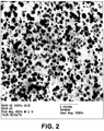
- the present inventors Due to the selective control over the polyepoxide modifier (e.g., activity, molecular weight, etc.) and the particular melt blending conditions, the present inventors have discovered that a morphology may be formed that enhances the reactivity with polylactic acid. More particularly, the resulting morphology may have a plurality of discrete phase domains of the polyepoxide modifier distributed throughout a continuous polylactic acid matrix. The domains may have a variety of different shapes, such as elliptical, spherical, cylindrical, etc. Regardless of the shape, however, the size of an individual domain, after blending, is small to provide an increased surface area for subsequent reaction with the polylactic acid.
- the polyepoxide modifier e.g., activity, molecular weight, etc.
- the size of a domain typically ranges from about 10 to about 1000 nanometers, in some embodiments from about 20 to about 800 nanometers, in some embodiments from about 40 to about 600 nanometers, and in some embodiments from about 50 to about 400 nanometers.
- the toughening additive may also form discrete domains within the polylactic acid matrix. When formed, such domains are typically larger than the polyepoxide domains.
- the toughening additive domains may have a dimension (e.g., length) of from about 0.5 ⁇ m to about 30 ⁇ m, and in some embodiments from about 1 ⁇ m to about 10 ⁇ m.
- the domains may be formed by a combination of the polyepoxide, toughening additive, and/or other components of the blend.
- the thermoplastic composition may nevertheless retain other properties of the starting polymer.
- the glass transition temperature (T g ) of the composition is typically the same as the glass transition temperature of polylactic acid. That is, the thermoplastic composition may have a T g of from about 50°C to about 80°C, and in some embodiments, from about 55°C to about 65°C.
- the melting point of the thermoplastic composition may also range from about 150°C to about 250°C, and in some embodiments, from about 160°C to about 220°C.
- the composition may be extruded through a spinneret, quenched, and drawn into the vertical passage of a fiber draw unit.
- the reaction of the polyepoxide modifier and polylactic acid may occur during this process, or it may occur prior to introduction to the fiber formation line.
- the blend may be supplied to an extruder (e.g., single screw) that includes a screw rotatably mounted and received within a barrel (e.g., cylindrical barrel), which may be heated.
- the blend is moved downstream from a feed end to a discharge end by forces exerted by rotation of the screw.
- Such screw extruders are typically divided into three sections along the length of the screw.
- the first section is a feed section where the solid material is introduced to the screw.
- the second section is a melting section where a majority of the melting of the solid occurs. Within this section, the screw generally possesses a tapered diameter to enhance melting of the polymer.
- the third section is the mixing section, which delivers the molten material in a constant amount for extrusion.
- the configuration of the screw is not particularly critical to the present invention and it may contain any number and/or orientation of threads and channels as is known in the art.
- the speed of the screw may also be selected to achieve the desired residence time, shear rate, melt processing temperature, etc.
- the screw speed may range from about 50 to about 200 revolutions per minute ("rpm"), in some embodiments from about 70 to about 150 rpm, and in some embodiments, from about 80 to about 120 rpm. This may result in a temperature that is greater than that normally used to extrude polylactic acid and sufficient high to initiate reaction of the polyepoxide modifier, such as above about 230°C.
- the extruder may employ one or multiple zones, at least one of which operates at a temperature of from about 230°C to about 350°C, in some embodiments from about 235°C to about 300°C, and in some embodiments, from about 240°C to about 280°C.
- the melt shear rate, and in turn the degree to which the reaction is initiated, may also be increased through the use of one or more distributive and/or dispersive mixing elements within the mixing section of the extruder.
- Suitable distributive mixers for single screw extruders may include, for instance, Saxon, Dulmage, Cavity Transfer mixers, etc.
- suitable dispersive mixers may include Blister ring, Leroy/Maddock, CRD mixers, etc.
- the mixing may be further improved by using pins in the barrel that create a folding and reorientation of the polymer melt, such as those used in Buss Kneader extruders, Cavity Transfer mixers, and Vortex Intermeshing Pin (VIP) mixers.
- VIP Vortex Intermeshing Pin
- the use of one more mixing elements may create intensive melt shear rates that help initiate the desired reaction.
- the apparent shear rate during melt processing may range from about 100 seconds -1 to about 10,000 seconds -1 , in some embodiments from about 200 seconds -1 to about 5000 seconds -1 , and in some embodiments, from about 500 seconds -1 to about 1200 seconds -1 .
- other variables such as the residence time during melt processing, which is inversely proportional to throughput rate, may also be controlled to achieve the desired degree of reaction.
- the molten plastic is desirably supplied to an underwater pelletizer system in which a polymer strand is cooled and solidified by circulating cooling water and thereafter cut in a water stream.
- the cooling water and/or stream may be maintained at a temperature of 5°C to about 30°C, and in some embodiments, from about 10°C to about 25°C.
- an underwater pelletizer system can allow the use of high exit pressures and/or temperatures at the die, which can force more of the lower viscosity polymeric toughening additive to the outer walls of the die and create the desired sheath component as it exits.
- the exit pressure may, for example, be about 100 pounds per square inch ("psi") or more, in some embodiments about 300 psi or more, and in some embodiments, about 500 psi or more.
- an underwater pelletizing system 110 contains an extruder 112 which supplies a molten polymer into a water chamber 118 through an extrusion die 114.
- the die 114 is coupled to the extruder 112 by one or more adaptors 116 and to the water chamber 118, either directly or with adaptors.
- a cutting system cuts the strands of polymer passing through the die 114 to form pellets.
- the cutting system may include, for instance, a motor 130 that drives a drive shaft 128 upon which is mounted, a cutting assembly 150.
- a controller 134 may be used to adjust the speed of the drive shaft 128.
- one or more screens may be employed within the extruder barrel that are optionally reinforced by a breaker plate.
- the screen pack/breaker plate assembly can help increase pressure.
- the amount of head pressure can be controlled by varying the configuration of the screen pack (the number of screens, hole size of the screens, etc.).
- the screen pack may include, for instance, from 2 to 15 screens, in some embodiments from 3 to 10 screens, and in some embodiments, from 4 to 8 screens.
- the upstream screens are generally of a size to collect only large particles while subsequent downstream screens are of a size to collect increasingly smaller particles.
- the pack employs at least one screen having openings of a relatively small size to create a high enough back pressure in the barrel.
- the screen may contain openings having an average width (or diameter) of about 100 micrometers or less, in some embodiments about 75 micrometers or less, and in some embodiments, from about 1 to about 50 micrometers.
- the pack employs multiple screens (e.g., 3 or more) having openings of this size.
- pellets formed from the blended thermoplastic composition may be formed into fibers using any of a variety of known techniques.
- Fig. 1 for example, one particular embodiment of a method for forming fibers is shown in more detail.
- the pellets are extruded at a relatively high temperature to induce the reaction between the epoxy functional group of the modifier and the polylactic acid, as well as to facilitate formation of the desired sheath/core configuration.
- the blend is fed into an extruder 12 from a hopper 14.
- the blend may be provided to the hopper 14 using any conventional technique.
- the extruded composition is then passed through a polymer conduit 16 to a spinneret 18.
- the spinneret 18 may include a housing containing a spin pack having a plurality of plates stacked one on top of each other and having a pattern of openings arranged to create flow paths for directing polymer components.
- the spinneret 18 also has openings arranged in one or more rows. The openings form a downwardly extruding curtain of filaments when the polymers are extruded therethrough.
- the process 10 also employs a quench blower 20 positioned adjacent the curtain of fibers extending from the spinneret 18. Air from the quench air blower 20 quenches the fibers extending from the spinneret 18.
- the quench air may be directed from one side of the fiber curtain as shown in Fig. 1 or both sides of the fiber curtain.
- the fiber draw unit 22 After quenching, the fibers are drawn into the vertical passage of a fiber draw unit 22.
- Fiber draw units or aspirators for use in melt spinning polymers are well-known in the art. Suitable fiber draw units for use in the process of the present invention include a linear fiber aspirator of the type shown in U.S. Patent Nos. 3,802,817 and 3,423,255 , which are incorporated herein in their entirety by reference thereto for all relevant purposes.
- the fiber draw unit 22 generally includes an elongated vertical passage through which the fibers are drawn by aspirating air entering from the sides of the passage and flowing downwardly through the passage.
- a heater or blower 24 supplies aspirating air to the fiber draw unit 22. The aspirating air draws the fibers and ambient air through the fiber draw unit 22.
- the flow of gas causes the fibers to draw or attenuate which increases the molecular orientation or crystallinity of the polymers forming the fibers.
- the fibers are deposited through the outlet opening of the fiber draw unit 22 and onto a godet roll 42. Due to the high strength of the fibers of the present invention, high draw ratios may be employed in the present invention.
- the draw ratio is the linear speed of the fibers after drawing (e.g., linear speed of the godet roll 42 or a foraminous surface (not shown) divided by the linear speed of the fibers after extrusion.
- the fibers collected on the godet roll 42 may optionally be subjected to additional in line processing and/or converting steps (not shown) as will be understood by those skilled in the art.
- staple fibers may be formed by "cold drawing" the collected fibers at a temperature below their softening temperature to the desired diameter, and thereafter crimping, texturizing, and/or and cutting the fibers to the desired fiber length.
- the staple fibers may, for instance, have a length in the range of from about 3 to about 80 millimeters, in some embodiments from about 4 to about 65 millimeters, and in some embodiments, from about 5 to about 50 millimeters.
- the staple fibers may then be incorporated into a nonwoven web as is known in the art, such as bonded carded webs, through-air bonded webs, etc.
- the fibers may also be deposited onto a foraminous surface to form a nonwoven web.
- a multi-component fiber contains a core component that is formed primarily from polylactic acid and a sheath component formed primarily from the polymeric toughening additive.
- the core component and/or sheath component may also contain other ingredients.
- the core component typically contains the polyepoxide modifier.
- a portion of the polymeric toughening additive from the original thermoplastic composition may also remain within the core component.
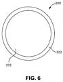
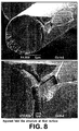
- the fiber includes a core component 202 that contains polylactic acid surrounded by a sheath component 302 that contains the polymeric toughening additive.
- a core component 202 that contains polylactic acid surrounded by a sheath component 302 that contains the polymeric toughening additive.
- the core component 202 and the sheath component 302 are arranged in distinctive zones across the cross section of the fibers.
- the core component 202 is shown substantially concentric with the sheath component 302. It should be understood, however, that the core and the sheath can be placed in various other arrangements. For instance, the core component 202 and the sheath component 302 can be placed in an eccentric arrangement as well.
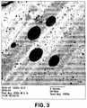
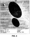
- the present inventors have also discovered that fiber drawing significantly increases the axial dimension of the reacted discrete domains so that they have a generally linear, elongated shape.
- the elongated domains may have an axial dimension that is about 10% or more, in some embodiments from about 50% to about 1000%, and in some embodiments, from about 100% to about 500% greater than the axial dimension of the domains prior to fiber drawing.
- the axial dimension after fiber drawing may, for instance, range from about 10 ⁇ m to about 300 ⁇ m, in some embodiments from about 40 ⁇ m to about 250 ⁇ m, and in some embodiments from about 50 ⁇ m to about 200 ⁇ m.
- the domains may also be relatively thin and thus have a small dimension in a direction orthogonal to the axial dimension (i.e., cross-sectional dimension).
- the cross-sectional dimension may be from about 0.02 to about 75 micrometers, in some embodiments from about 0.1 to about 40 micrometers, and in some embodiments, from 0.4 to about 20 micrometers in length. This may result in an aspect ratio for the domains (the ratio of the axial dimension to the cross-sectional dimension) of from about 3 to about 200, in some embodiments from about 5 to about 100, and in some embodiments, from about 5 to about 50.
- the presence of these elongated domains is indicative of the ability of the thermoplastic composition to absorb energy imparted during fiber drawing.
- the composition is not as brittle as neat polylactic acid and thus can release upon the application of strain, rather than fracture.
- the polymer may continue to function as a load bearing member even after the fiber has exhibited substantial elongation.
- the fibers of the present invention are capable of exhibiting improved "peak elongation" properties, i.e., the percent elongation of the fiber at its peak load.
- the fibers of the present invention may exhibit a peak elongation of about 25% or more, in some embodiments about 30% or more, in some embodiments from about 40% to about 350%, and in some embodiments, from about 50% to about 250%.
- Such elongations may be achieved for fibers having a wide variety of average diameters, such as those ranging from about 0.1 to about 50 micrometers, in some embodiments from about 1 to about 40 micrometers, in some embodiments from about 2 to about 25 micrometers, and in some embodiments, from about 5 to about 15 micrometers.
- the fibers of the present invention can also remain relatively strong.
- One parameter that is indicative of the relative strength of the fibers of the present invention is "tenacity", which indicates the tensile strength of a fiber expressed as force per unit linear density.
- the fibers of the present invention may have a tenacity of from about 0.75 to about 6.0 grams-force ("g f ”) per denier, in some embodiments from about 1.0 to about 4.5 g f per denier, and in some embodiments, from about 1.5 to about 4.0 g f per denier.
- the denier of the fibers may vary depending on the desired application.
- the fibers are formed to have a denier per filament (i.e., the unit of linear density equal to the mass in grams per 9000 meters of fiber) of less than about 6, in some embodiments less than about 3, and in some embodiments, from about 0.5 to about 3.
- a denier per filament i.e., the unit of linear density equal to the mass in grams per 9000 meters of fiber
- the fibers of the present invention may also be formed into a coherent web structure by randomly depositing the fibers onto a forming surface (optionally with the aid of a vacuum) and then bonding the resulting web using any known technique.
- a forming surface may be positioned below the fiber draw unit and receive the fibers from an outlet opening.
- a vacuum may be positioned below the forming surface to draw the fibers and consolidate the unbonded nonwoven web.
- the nonwoven web may then be bonded using any conventional technique, such as with an adhesive or autogenously (e.g., fusion and/or self-adhesion of the fibers without an applied external adhesive).
- Autogenous bonding may be achieved through contact of the fibers while they are semi-molten or tacky, or simply by blending a tackifying resin and/or solvent with the polylactic acid(s) used to form the fibers.
- Suitable autogenous bonding techniques may include ultrasonic bonding, thermal bonding, through-air bonding, calendar bonding, and so forth.
- the web may be further bonded or embossed with a pattern by a thermo-mechanical process in which the web is passed between a heated smooth anvil roll and a heated pattern roll.
- the pattern roll may have any raised pattern which provides the desired web properties or appearance.
- the pattern roll defines a raised pattern which defines a plurality of bond locations which define a bond area between about 2% and 30% of the total area of the roll.
- Exemplary bond patterns include, for instance, those described in U.S. Patent 3,855,046 to Hansen et al. , U.S. Patent No. 5,620,779 to Levy et al. , U.S. Patent No. 5,962,112 to Haynes et al. , U.S. Patent 6,093,665 to Sayovitz et al., as well as U.S. Design Patent Nos. 428,267 to Romano et al. ; 390,708 to Brown ; 418,305 to Zander, et al.
- the pressure between the rolls may be from about 5 to about 2000 pounds per lineal inch.
- the pressure between the rolls and the temperature of the rolls is balanced to obtain desired web properties or appearance while maintaining cloth like properties. As is well known to those skilled in the art, the temperature and pressure required may vary depending upon many factors including but not limited to, pattern bond area, polymer properties, fiber properties and nonwoven properties.
- thermoplastic composition in accordance with the present invention, such as meltblown webs, bonded carded webs, wet-laid webs, airlaid webs, coform webs, hydraulically entangled webs, etc.
- the thermoplastic composition may be extruded through a plurality of fine die capillaries into a converging high velocity gas (e.g., air) streams that attenuate the fibers to reduce their diameter. Thereafter, the meltblown fibers are carried by the high velocity gas stream and are deposited on a collecting surface to form a web of randomly dispersed meltblown fibers.
- high velocity gas e.g., air
- the polymer may be formed into a carded web by placing bales of fibers formed from the thermoplastic composition into a picker that separates the fibers. Next, the fibers are sent through a combing or carding unit that further breaks apart and aligns the fibers in the machine direction so as to form a machine direction-oriented fibrous nonwoven web. Once formed, the nonwoven web is typically stabilized by one or more known bonding techniques.
- the nonwoven web may also be a composite that contains a combination of the thermoplastic composition fibers and other types of fibers (e.g., staple fibers, filaments, etc).
- additional synthetic fibers may be utilized, such as those formed from polyolefins, e.g., polyethylene, polypropylene, polybutylene, and so forth; polytetrafluoroethylene; polyesters, e.g., polyethylene terephthalate and so forth; polyvinyl acetate; polyvinyl chloride acetate; polyvinyl butyral; acrylic resins, e.g., polyacrylate, polymethylacrylate, polymethylmethacrylate, and so forth; polyamides, e.g., nylon; polyvinyl chloride; polyvinylidene chloride; polystyrene; polyvinyl alcohol; polyurethanes; polylactic acid; etc.
- biodegradable polymers such as poly(glycolic acid) (PGA), poly(lactic acid) (PLA), poly( ⁇ -malic acid) (PMLA), poly( ⁇ -caprolactone) (PCL), poly(p-dioxanone) (PDS), poly(butylene succinate) (PBS), and poly(3-hydroxybutyrate) (PHB), may also be employed.
- PGA poly(glycolic acid)
- PLA poly(lactic acid)
- PMLA poly( ⁇ -malic acid)
- PCL poly( ⁇ -caprolactone)
- PDS poly(p-dioxanone)
- PBS poly(butylene succinate)
- PBS poly(3-hydroxybutyrate)
- PBS poly(3-hydroxybutyrate)
- bicomponent fibers that may be used include those available from the Chisso Corporation of Moriyama, Japan or Fibervisions LLC of Wilmington, Delaware.
- Polylactic acid staple fibers may also be employed, such as those commercially available from Far Eastern Textile, Ltd. of Taiwan.
- the composite may also contain pulp fibers, such as high-average fiber length pulp, low-average fiber length pulp, or mixtures thereof.
- suitable high-average length fluff pulp fibers includes softwood kraft pulp fibers.
- Softwood kraft pulp fibers are derived from coniferous trees and include pulp fibers such as, but not limited to, northern, western, and southern softwood species, including redwood, red cedar, hemlock, Douglas fir, true firs, pine (e.g., southern pines), spruce (e.g., black spruce), bamboo, combinations thereof, and so forth.
- Northern softwood kraft pulp fibers may be used in the present invention.
- An example of commercially available southern softwood kraft pulp fibers suitable for use in the present invention include those available from Weyerhaeuser Company with offices in Federal Way, Washington under the trade designation of "NF-405.”
- Another suitable pulp for use in the present invention is a bleached, sulfate wood pulp containing primarily softwood fibers that is available from Bowater Corp. with offices in Greenville, South Carolina under the trade name CoosAbsorb S pulp.
- Low-average length fibers may also be used in the present invention.
- An example of suitable low-average length pulp fibers is hardwood kraft pulp fibers.
- Hardwood kraft pulp fibers are derived from deciduous trees and include pulp fibers such as, but not limited to, eucalyptus, maple, birch, aspen, etc.
- Eucalyptus kraft pulp fibers may be particularly desired to increase softness, enhance brightness, increase opacity, and change the pore structure of the sheet to increase its wicking ability.
- bamboo or cotton fibers may also be
- Nonwoven composites may be formed using a variety of known techniques.
- the nonwoven composite may be a "coform material" that contains a mixture or stabilized matrix of the thermoplastic composition fibers and an absorbent material.
- coform materials may be made by a process in which at least one meltblown die head is arranged near a chute through which the absorbent materials are added to the web while it is forming.
- absorbent materials may include, but are not limited to, pulp fibers, superabsorbent particles, inorganic and/or organic absorbent materials, treated polymeric staple fibers, and so forth. The relative percentages of the absorbent material may vary over a wide range depending on the desired characteristics of the nonwoven composite.
- the nonwoven composite may contain from about 1 wt.% to about 60 wt.%, in some embodiments from 5 wt.% to about 50 wt.%, and in some embodiments, from about 10 wt.% to about 40 wt.% thermoplastic composition fibers.
- the nonwoven composite may likewise contain from about 40 wt.% to about 99 wt.%, in some embodiments from 50 wt.% to about 95 wt.%, and in some embodiments, from about 60 wt.% to about 90 wt.% absorbent material.
- Some examples of such coform materials are disclosed in U.S. Patent Nos. 4,100,324 to Anderson, et al. ; 5,284,703 to Everhart, et al. ; and 5,350,624 to Georger, et al .; which are incorporated herein in their entirety by reference thereto for all purposes.
- Nonwoven laminates may also be formed in the present invention in which one or more layers are formed from the thermoplastic composition.
- the nonwoven web of one layer may be a spunbond that contains the thermoplastic composition, while the nonwoven web of another layer contains thermoplastic composition, other biodegradable polymer(s), and/or any other polymer (e.g., polyolefins).
- the nonwoven laminate contains a meltblown layer positioned between two spunbond layers to form a spunbond / meltblown / spunbond (“SMS”) laminate. If desired, the spunbond layer(s) may be formed from the thermoplastic composition.
- SMS spunbond / meltblown / spunbond
- the meltblown layer may be formed from the thermoplastic composition, other biodegradable polymer(s), and/or any other polymer (e.g., polyolefins).
- Various techniques for forming SMS laminates are described in U.S. Patent Nos. 4,041,203 to Brock et al. ; 5,213,881 to Timmons, et al. ; 5,464,688 to Timmons, et al. ; 4,374,888 to Bornslaeger ; 5,169,706 to Collier, et al. ; and 4,766,029 to Brock et al. , as well as U.S. Patent Application Publication No. 2004/0002273 to Fitting, et al.
- the nonwoven laminate may have other configuration and possess any desired number of meltblown and spunbond layers, such as spunbond / meltblown / meltblown / spunbond laminates ("SMMS”), spunbond / meltblown laminates ("SM”), etc.
- SMMS spunbond / meltblown / spunbond laminates
- SM spunbond / meltblown laminates
- the basis weight of the nonwoven laminate may be tailored to the desired application, it generally ranges from about 10 to about 300 grams per square meter (“gsm”), in some embodiments from about 25 to about 200 gsm, and in some embodiments, from about 40 to about 150 gsm.
- the nonwoven web or laminate may be applied with various treatments to impart desirable characteristics.
- the web may be treated with liquid-repellency additives, antistatic agents, surfactants, colorants, antifogging agents, fluorochemical blood or alcohol repellents, lubricants, and/or antimicrobial agents.
- the web may be subjected to an electret treatment that imparts an electrostatic charge to improve filtration efficiency.
- the charge may include layers of positive or negative charges trapped at or near the surface of the polymer, or charge clouds stored in the bulk of the polymer.
- the charge may also include polarization charges that are frozen in alignment of the dipoles of the molecules. Techniques for subjecting a fabric to an electret treatment are well known by those skilled in the art.
- the electret treatment is a corona discharge technique, which involves subjecting the laminate to a pair of electrical fields that have opposite polarities.
- Other methods for forming an electret material are described in U.S. Patent Nos. 4,215,682 to Kubik, et al. ; 4,375,718 to Wadsworth ; 4,592,815 to Nakao ; 4,874,659 to Ando ; 5,401,446 to Tsai, et al. ; 5,883,026 to Reader, et al. ; 5,908,598 to Rousseau, et al. ; 6,365,088 to Knight, et al. , which are incorporated herein in their entirety by reference thereto for all purposes.
- the nonwoven web may be used in a wide variety of applications.
- the web may be incorporated into a "medical product", such as gowns, surgical drapes, facemasks, head coverings, surgical caps, shoe coverings, sterilization wraps, warming blankets, heating pads, and so forth.
- the nonwoven web may also be used in various other articles.
- the nonwoven web may be incorporated into an "absorbent article" that is capable of absorbing water or other fluids.
- absorbent articles examples include, but are not limited to, personal care absorbent articles, such as diapers, training pants, absorbent underpants, incontinence articles, feminine hygiene products (e.g., sanitary napkins), swim wear, baby wipes, mitt wipe, and so forth; medical absorbent articles, such as garments, fenestration materials, underpads, bedpads, bandages, absorbent drapes, and medical wipes; food service wipers; clothing articles; pouches, and so forth. Materials and processes suitable for forming such articles are well known to those skilled in the art.
- Absorbent articles typically include a substantially liquid-impermeable layer (e.g., outer cover), a liquid-permeable layer (e.g., bodyside liner, surge layer, etc.), and an absorbent core.
- a nonwoven web formed according to the present invention may be used to form an outer cover of an absorbent article. If desired, the nonwoven web may be laminated to a liquid-impermeable film that is either vapor-permeable or vapor-impermeable.
- polylactic acid was dried in a dessicant at a temperature of about 77°C prior to blending with the polyepoxide modifier.
- the resulting blend was also dried in a dessicant dryer at a temperature of from 125°F to 150°F prior to fiber spinning.
- Fibers formed from 100% polylactic acid (PLA) were formed as a control by extruding PLA 6201 D (Natureworks®, melt flow rate of 10 g/10 min at 190°C) into fiber form. More specifically, polylactic acid was supplied to an extruder heated to a temperature of 235°C. The throughput of the extruder was 0.4 grams per hole per minute (on a 16 hole per inch spinpack). The melt was extruded through the spinpack to form continuous fibers which were then quenched using forced air supplied by a blower a temperature of 25°C. The continuous fibers were then drawn through a fiber draw unit and sent them onto a godet roll at a speed of 2000 meters per minute ("mpm"). The resulting draw ratio was 1549. Fibers were collected at 2000 mpm to provide a target 15 ⁇ m fiber. Fibers were then drawn onto a godet roll at a speed of 3000 meters per minute (“mpm”). The resulting draw ratio was 2324.
- the ability to form fibers from a blend of 97 wt.% polylactic acid (PLA 6201 D, Natureworks®) and 3 wt.% of a polyepoxide modifier was demonstrated.
- the polyepoxide modifier was poly(ethylene-co-methyl acrylate-co-glycidyl methacrylate) (Sigma-Aldrich Co.) having a melt flow rate of 6 g/10 min
- Thermo PrismTM USALAB 16 twin screw extruder (Thermo Electron Corp., Stone, England).
- the melt temperature of the extruder was 195°C.
- the extruder had 11 zones, numbered consecutively 0-10 from the feed hopper to the die.
- the polylactic acid resin was dry mixed with the polyepoxide modifier and fed to the feed throat of the extruder (un-heated, before zone 1 of the extruder) at a rate of 3 pounds per hour.
- the screw speed was 200 revolutions per minute ("rpm").
- the die used to extrude the resin had 1 die openings (3 millimeters in diameter).
- the extruded resin was cooled on a fan-cooled conveyor belt and formed into pellets.
- the pellets were then supplied to an extruder heated to a temperature of 240°C.
- the throughput of the extruder was 0.4 grams per hole per minute (on a 16 hole per inch spinpack).
- the melt was extruded through the spinpack to form continuous fibers which were then quenched using forced air supplied by a blower a temperature of 25°C.
- the continuous fibers were then drawn onto a godet roll at a speed of 2000 meters per minute ("mpm").
- the resulting draw ratio was 1549.
- Fibers were formed from a blend of 95 wt.% polylactic acid (PLA 6201 D, Natureworks®) and 5 wt.% of poly(ethylene-co-methyl acrylate-co-glycidyl methacrylate) (Sigma-Aldrich Co.) as described in Example 2.
- the continuous fibers were then drawn onto a godet roll at a speed of 2000 meters per minute ("mpm”). The resulting draw ratio was 1549. Fibers were also spun at 3000 meters per minute (“mpm”) for a resulting draw ratio of 2324.
- Fibers were formed from a blend of 90 wt.% polylactic acid (PLA 6201 D, Natureworks®) and 10 wt.% of poly(ethylene-co-methyl acrylate-co-glycidyl methacrylate) (Sigma-Aldrich Co.) as described in Example 2, except that the fibers were extruded at 215°C and drawn onto a godet roll at 500 mpm with a resulting draw ratio of 387. Prior to formation of the fibers, transmission electron microscopy (“TEM”) was also employed to view the blend. An image of the blend at 10.000X is shown in Fig. 2 . As shown, the blend contains a plurality of small domains as evidenced by the darkened areas.
- TEM transmission electron microscopy
- Pellets were formed from a blend of 85 wt.% polylactic acid (PLA 6201 D, Natureworks®) and 15 wt.% of poly(ethylene-co-methyl acrylate-co-glycidyl methacrylate) (Sigma-Aldrich Co.) as described in Example 2. The resulting pellets were not fiber spun.
- Fibers were formed from a blend of 90 wt.% polylactic acid (PLA 6201 D, Natureworks®) and 10 wt.% of a polyepoxide modifier.
- the polyepoxide modifier was poly(ethylene-co-methyl acrylate-co-glycidyl methacrylate) (Lotader® AX8950, Arkema) having a melt flow rate of 70-100 g/10 min (190°C/2160 g), a glycidyl methacrylate content of 7 to 11 wt.%, methyl acrylate content of 13 to 17 wt.%, and ethylene content of 72 to 80 wt.%.
- the same process was employed as in Example 2, except that the fibers were extruded at 210°C and drawn onto a godet roll at a speed of 800 mpm resulting in a draw ratio of 620.
- Pellets were formed from a blend of 90 wt.% polylactic acid (PLA 6201 D, Natureworks®) and 10 wt.% of poly(ethylene-co-methyl acrylate-co-glycidyl methacrylate) (Sigma-Aldrich Co.) as described in Example 2, except that the polymer were blended together at a melt temperature of 235°C. The resulting pellets were not fiber spun.
- PLA 6201 D Poly(ethylene-co-methyl acrylate-co-glycidyl methacrylate)
- the ability to form fibers from a blend of 88.7 wt.% polylactic acid (PLA 6201 D, Natureworks®), 1.5 wt.% of a polyepoxide modifier, and 9.8 wt.% of a toughening additive was demonstrated.
- the polyepoxide modifier was poly(ethylene-co-methyl acrylate-co-glycidyl methacrylate) (Lotader® AX8950, Arkema).
- the toughening additive was VistamaxxTM 2120 (Exxonmobil), which is a polyolefin copolymer/elastomer with a melt flow rate of 29 g/10 min (190°C, 2160g) and a density of 0.866 g/cm 3 .
- the polymers were fed into a co-rotating, twin-screw extruder (ZSK-30, diameter of 30 mm, length of 1328 millimeters) was employed for compounding that was manufactured by Werner and Pfleiderer Corporation of Ramsey, New Jersey.
- the extruder possessed 14 zones, numbered consecutively 1-14 from the feed hopper to the die.
- the first barrel #1 received the resins via gravimetric feeder at a total throughput of 15 pounds per hour.
- the die used to extrude the resin had 3 die openings (6 millimeters in diameter) that were separated by 4 millimeters.
- the extruded resin was cooled on a fan-cooled conveyor belt and formed into pellets by a Conair pelletizer.
- the screw speed was 100 revolutions per minute ("rpm").
- the pellets were then supplied to an extruder heated to a temperature of 220°C.
- the throughput of the extruder was 0.4 grams per hole per minute (on a 16 hole per inch spinpack).
- the melt was extruded through the spinpack to form continuous fibers which were then quenched using forced air supplied by a blower a temperature of 25°C.
- the continuous fibers were then drawn onto a godet roll at a speed of 1000 meters per minute ("mpm"). The resulting draw ratio was 775.
- Fibers were formed as described in Example 8, except that the temperature at which the fibers were extruded was 240°C and the draw speed of the godet roll was 1000 meters per minute ("mpm"). The resulting draw ratio was 775.
- Fibers were formed as described in Example 8, except that the toughening additive was EscoreneTM Ultra 7720 (Exxonmobil), which is an ethylene vinyl acetate (“EVA”) resin, which has a melt flow rate of 150 g/10min and a density of 0.946 g/cm 3 and the draw speed of the godet roll was 700 meters per minute (“mpm”). The resulting draw ratio was 542.
- EscoreneTM Ultra 7720 Exxonmobil
- EVA ethylene vinyl acetate
- Fibers were formed as described in Example 10, except that the temperature at which the fibers were extruded was 240°C and the draw speed of the godet roll was 1000 meters per minute ("mpm"). The resulting draw ratio was 775.
- Fibers were formed as described in Example 10, except that the temperature at which the fibers were extruded was 230°C.
- Fibers were formed as described in Example 8, except that the temperature at which the polymers were blended was 235°C and the temperature at which the fibers were extruded was 235°C and the draw speed of the godet roll was 3000 meters per minute ("mpm"). The resulting draw ratio was 2324.
- the ability to form fibers from a blend of 89.6 wt.% polylactic acid (PLA 6201 D, Natureworks®), 0.5 wt.% of a polyepoxide modifier, and 9.9 wt.% of a toughening additive was demonstrated.
- the polyepoxide modifier was poly(ethylene-co-methyl acrylate-co-glycidyl methacrylate) (Lotader® AX8950, Arkema).
- the toughening additive was VistamaxxTM 2120 (Exxonmobil).
- the polymers were fed into a co-rotating, twin-screw extruder (ZSK-30, diameter of 30 mm, length of 1328 millimeters) was employed for compounding that was manufactured by Werner and Pfleiderer Corporation of Ramsey, New Jersey.
- the extruder possessed 14 zones, numbered consecutively 1-14 from the feed hopper to the die.
- the first barrel #1 received the resins via gravimetric feeder at a total throughput of 15 pounds per hour.
- the die used to extrude the resin had 3 die openings (6 millimeters in diameter) that were separated by 4 millimeters.
- the extruded resin was cooled on a fan-cooled conveyor belt and formed into pellets by a Conair pelletizer.
- the screw speed was 100 revolutions per minute ("rpm").
- the pellets were then supplied to an extruder heated to a temperature of 220°C.
- the throughput of the extruder was 0.4 grams per hole per minute (on a 16 hole per inch spinpack).
- the melt was extruded through the spinpack to form continuous fibers which were then quenched using forced air supplied by a blower a temperature of 25°C.
- the continuous fibers were then drawn onto a godet roll at a speed of 500 meters per minute ("mpm"). The resulting draw ratio was 387. Fibers could not be collected.
- Fibers were formed as described in Example 14, except that the temperature at which the fibers were extruded was 225°C and the speed of the godet roll was 750 mpm. Fibers could not be collected.
- Fibers were formed as described in Example 14, except that the temperature at which the fibers were extruded was 230°C and the speed of the godet roll was 1500 mpm. Fibers could not be collected.
- Fibers were formed as described in Example 14, except that the temperature at which the fibers were extruded was 235°C and the speed of the godet roll was 2000 mpm. Fibers were collected at 2000 mpm and fibers were spun up to 3000 mpm.
- Fibers were formed as described in Example 14, except that the temperature at which the fibers were extruded was 240°C and the speed of the godet roll was 2000 mpm. Fibers were collected at 2000 mpm and fibers were spun up to 3000 mpm.
- Fibers were formed as described in Example 14, except that the temperature at which the fibers were extruded was 245°C and the speed of the godet roll was 2000 mpm. Fibers were collected at 2000 mpm and fibers were spun up to 2800 mpm.
- Fibers were formed as described in Example 14, except that the temperature at which the fibers were extruded was 250°C and the speed of the godet roll was 2000 mpm. Fibers were collected at 2000 mpm and fibers were spun up to 2900 mpm.
- the ability to form fibers from a blend of 88.7 wt.% polylactic acid (PLA 6201 D, Natureworks®), 1.5 wt.% of a polyepoxide modifier, and 9.8 wt.% of a toughening additive was demonstrated.
- the polyepoxide modifier was poly(ethylene-co-methyl acrylate-co-glycidyl methacrylate) (Lotader® AX8950, Arkema).
- the toughening additive was VistamaxxTM 2120 (Exxonmobil).
- the polymers were fed into a co-rotating, twin-screw extruder (ZSK-30, diameter of 30 mm, length of 1328 millimeters) was employed for compounding that was manufactured by Werner and Pfleiderer Corporation of Ramsey, New Jersey.
- the extruder possessed 14 zones, numbered consecutively 1-14 from the feed hopper to the die.
- the first barrel #1 received the resins via gravimetric feeder at a total throughput of 15 pounds per hour.
- the die used to extrude the resin had 3 die openings (6 millimeters in diameter) that were separated by 4 millimeters.
- the extruded resin was cooled on a fan-cooled conveyor belt and formed into pellets by a Conair pelletizer.
- the screw speed was 100 revolutions per minute ("rpm").
- the pellets were then supplied to an extruder heated to a temperature of 220°C.
- the throughput of the extruder was 0.4 grams per hole per minute (on a 16 hole per inch spinpack).
- the melt was extruded through the spinpack to form continuous fibers which were then quenched using forced air supplied by a blower a temperature of 25°C.
- the continuous fibers were then drawn onto a godet roll at a speed of 500 meters per minute ("mpm"). The resulting draw ratio was 387. Fibers could not be collected.
- Fibers were formed as described in Example 21, except that the temperature at which the fibers were extruded was 225°C and the speed of the godet roll was 1200 mpm. Fibers could not be collected.
- Fibers were formed as described in Example 21, except that the temperature at which the fibers were extruded was 230°C and the speed of the godet roll was 2000 mpm. Fibers were collected at 2000 mpm and fibers were spun up to 2400 mpm.
- Fibers were formed as described in Example 21, except that the temperature at which the fibers were extruded was 235°C and the speed of the godet roll was 2000 mpm. Fibers were collected at 2000 mpm and fibers were spun up to 3000 mpm.
- Fibers were formed as described in Example 21, except that the temperature at which the fibers were extruded was 240°C and the speed of the godet roll was 2000 mpm. Fibers were collected at 2000 mpm and fibers were spun up to 3000 mpm.
- Fibers were formed as described in Example 21, except that the temperature at which the fibers were extruded was 245°C and the speed of the godet roll was 2000 mpm. Fibers were collected at 2000 mpm and fibers were spun up to 3000 mpm.
- Fibers were formed as described in Example 21, except that the temperature at which the fibers were extruded was 250°C and the speed of the godet roll was 2000 mpm. Fibers were collected at 2000 mpm and fibers were spun up to 2800 mpm.
- the ability to form fibers from a blend of 87.8 wt.% polylactic acid (PLA 6201 D, Natureworks®), 2.4 wt.% of a polyepoxide modifier, and 9.8 wt.% of a toughening additive was demonstrated.
- the polyepoxide modifier was poly(ethylene-co-methyl acrylate-co-glycidyl methacrylate) (Lotader® AX8950, Arkema).
- the toughening additive was VistamaxxTM 2120 (Exxonmobil).
- the polymers were fed into a co-rotating, twin-screw extruder (ZSK-30, diameter of 30 mm, length of 1328 millimeters) was employed for compounding that was manufactured by Werner and Pfleiderer Corporation of Ramsey, New Jersey.
- the extruder possessed 14 zones, numbered consecutively 1-14 from the feed hopper to the die.
- the first barrel #1 received the resins via gravimetric feeder at a total throughput of 15 pounds per hour.
- the die used to extrude the resin had 3 die openings (6 millimeters in diameter) that were separated by 4 millimeters.
- the extruded resin was cooled on a fan-cooled conveyor belt and formed into pellets by a Conair pelletizer.
- the screw speed was 100 revolutions per minute ("rpm").
- the pellets were then supplied to an extruder heated to a temperature of 220°C.
- the throughput of the extruder was 0.4 grams per hole per minute (on a 16 hole per inch spinpack).
- the melt was extruded through the spinpack to form continuous fibers which were then quenched using forced air supplied by a blower a temperature of 25°C.
- the continuous fibers were then drawn onto a godet roll at a speed of 1300 meters per minute ("mpm"). The resulting draw ratio was 387. Fibers could not be collected.
- Fibers were formed as described in Example 28, except that the temperature at which the fibers were extruded was 225°C and the speed of the godet roll was 1500 mpm. Fibers could not be collected.
- Fibers were formed as described in Example 28, except that the temperature at which the fibers were extruded was 230°C and the speed of the godet roll was 2000 mpm. Fibers were collected at 2000 mpm and fibers were spun up to 3000 mpm.
- Fibers were formed as described in Example 28, except that the temperature at which the fibers were extruded was 235° and the speed of the godet roll was 2000 mpm. Fibers were collected at 2000 mpm and fibers were spun up to 2900 mpm.
- Fibers were formed as described in Example 28, except that the temperature at which the fibers were extruded was 240°C and the speed of the godet roll was 2000 mpm. Fibers were collected at 2000 mpm and fibers were spun up to 3000 mpm.
- Fibers were formed as described in Example 28, except that the temperature at which the fibers were extruded was 245°C and the speed of the godet roll was 2000 mpm. Fibers were collected at 2000 mpm and fibers were spun up to 3000 mpm.
- Fibers were formed as described in Example 28, except that the temperature at which the fibers were extruded was 250°C and the speed of the godet roll was 2000 mpm. Fibers were collected at 2000 mpm and fibers were spun up to 2800 mpm.
- the ability to form fibers from a blend of 88.7 wt.% polylactic acid (PLA 6201 D, Natureworks®), 1.5 wt.% of a polyepoxide modifier, and 9.8 wt.% of a toughening additive was demonstrated.
- the polyepoxide modifier was poly(ethylene-co-methyl acrylate-co-glycidyl methacrylate) (Lotader® AX8950, Arkema).
- the toughening additive was VistamaxxTM 2120 (Exxonmobil).
- the polymers were fed into a co-rotating, twin-screw extruder (ZSK-30, diameter of 30 mm, length of 1328 millimeters) was employed for compounding that was manufactured by Werner and Pfleiderer Corporation of Ramsey, New Jersey.
- the extruder possessed 14 zones, numbered consecutively 1-14 from the feed hopper to the die.
- the first barrel #1 received the resins via gravimetric feeder at a total throughput of 15 pounds per hour.
- the die used to extrude the resin had 3 die openings (6 millimeters in diameter) that were separated by 4 millimeters.
- the extruded resin was cooled on a fan-cooled conveyor belt and formed into pellets by a Conair pelletizer.
- the screw speed was 200 revolutions per minute ("rpm").
- the pellets were then supplied to an extruder heated to a temperature of 220°C.
- the throughput of the extruder was 0.4 grams per hole per minute (on a 16 hole per inch spinpack).
- the melt was extruded through the spinpack to form continuous fibers which were then quenched using forced air supplied by a blower a temperature of 25°C.
- the continuous fibers were then drawn onto a godet roll at a speed of 2000 meters per minute ("mpm"). The resulting draw ratio was 1547. Fibers were collected and then godet roll was increased to 3000 mpm.
- Fibers were formed as described in Example 35, except that the temperature at which the fibers were extruded was 230°C and the speed of the godet roll was 2000 mpm. Fibers were collected at 2000 mpm and fibers were spun up to 3000 mpm.
- Fibers were formed as described in Example 35, except that the temperature at which the fibers were extruded was 235°C and the speed of the godet roll was 2000 mpm. Fibers were collected at 2000 mpm and fibers were spun up to 3000 mpm.
- Fibers were formed as described in Example 35, except that the temperature at which the fibers were extruded was 240°C and the speed of the godet roll was 2000 mpm. Fibers were collected at 2000 mpm and fibers were spun up to 3000 mpm.
- Fibers were formed as described in Example 35, except that the temperature at which the fibers were extruded was 245°C and the speed of the godet roll was 2000 mpm.
- Fibers were formed as described in Example 35, except that the temperature at which the fibers were extruded was 250°C and the speed of the godet roll was 2000 mpm. Fibers were collected at 2000 mpm and fibers were spun up to 3000 mpm.
- Fibers were formed as described in Example 35, except that the temperature at which the fibers were extruded was 255° and the speed of the godet roll was 2000 mpm. Fibers were collected at 2000 mpm and fibers were spun up to 3000 mpm.
- Fibers were from a blend of 88.7 wt.% polylactic acid (PLA 6201 D, Natureworks®), 9.8 wt.% of a toughening additive, and 1.5 wt.% of a polyepoxide modifier was also employed.
- the polyepoxide modifier was poly(ethylene-co-methyl acrylate-co-glycidyl methacrylate) (Lotader® AX8950, Arkema).
- the toughening additive was PP 3155 (Exxonmobil), a polypropylene homopolymer.
- the polymers were fed into a co-rotating, twin-screw extruder (ZSK-30, diameter of 30 mm, length of 1328 millimeters) was employed for compounding that was manufactured by Werner and Pfleiderer Corporation of Ramsey, New Jersey.
- the extruder possessed 14 zones, numbered consecutively 1-14 from the feed hopper to the die.
- the first barrel #1 received the resins via gravimetric feeder at a total throughput of 15 pounds per hour.
- the die used to extrude the resin had 3 die openings (6 millimeters in diameter) that were separated by 4 millimeters.
- the extruded resin was cooled on a fan-cooled conveyor belt and formed into pellets by a Conair pelletizer.
- the screw speed was 100 revolutions per minute ("rpm").
- the pellets were then supplied to an extruder heated to a temperature of 230°C.
- the throughput of the extruder was 0.4 grams per hole per minute (on a 16 hole per inch spinpack).
- the melt was extruded through the spinpack to form continuous fibers which were then quenched using forced air supplied by a blower a temperature of 25°C.
- the continuous fibers were then drawn onto a godet roll at a speed of 2000 meters per minute ("mpm”). Fibers were collected at 2000 mpm and fibers were spun up to 3000 mpm.
- Fibers were formed as described in Example 42, except that the temperature at which the fibers were extruded was 235°C and the speed of the godet roll was 2000 mpm. Fibers were collected at 2000 mpm and fibers were spun up to 3000 mpm.
- Fibers were formed as described in Example 42, except that the temperature at which the fibers were extruded was 240°C and the speed of the godet roll was 2000 mpm. Fibers were collected at 2000 mpm and fibers were spun up to 3000 mpm.
- the ability to form fibers from a blend of 89.25 wt.% polylactic acid (PLA 6201 D, Natureworks®), 0.75 wt.% of a polyepoxide modifier, and 10 wt.% of a toughening additive was demonstrated.
- the polyepoxide modifier was poly(ethylene-co-methyl acrylate-co-glycidyl methacrylate) (Lotader® AX8900, Arkema).
- the toughening additive was PP 3155 (Exxon-Mobil), a polypropylene homopolymer.
- the polymers were fed into a co-rotating, twin-screw extruder (ZSK-30, diameter of 30 mm, length of 1328 millimeters) was employed for compounding that was manufactured by Werner and Pfleiderer Corporation of Ramsey, New Jersey.
- the extruder possessed 14 zones, numbered consecutively 1-14 from the feed hopper to the die.
- the first barrel #1 received the resins via gravimetric feeder at a total throughput of 15 pounds per hour.
- the die used to extrude the resin had 3 die openings (6 millimeters in diameter) that were separated by 4 millimeters.
- the extruded resin was cooled on a fan-cooled conveyor belt and formed into pellets by a Conair pelletizer.
- the screw speed was 200 revolutions per minute ("rpm").
- the extruded resin was cooled on a fan-cooled conveyor belt and formed into pellets.
- the pellets were then supplied to an extruder heated to a temperature of 240°C.
- the throughput of the extruder was 0.4 grams per hole per minute (on a 16 hole per inch spinpack).
- the melt was extruded through the spinpack to form continuous fibers which were then quenched using forced air supplied by a blower a temperature of 25°C.
- the continuous fibers were then drawn onto a godet roll at a speed of 2000 meters per minute ("mpm").
- the resulting draw ratio was 1547. Fibers were collected and then godet roll was increased to 3000 mpm.
- the extruder throughput was then decreased to 0.28 grams per hole per minute and fibers were drawn onto a godet roll at 3000 mpm resulting in a draw ratio of 3320.
- Fibers were formed as described in Example 45, except that the temperature at which the fibers were extruded was 245°C and the speed of the godet roll was 2000 mpm. Fibers were not collected.
- Fibers were formed as described in Example 45, except that the temperature at which the fibers were extruded was 250°C and the speed of the godet roll was 2000 mpm. Fibers were not collected.
- Fibers were formed as described in Example 45, except that concentration of LotaderTM AX8900 was 0.5% and the speed of the godet roll was 2000 mpm. Fibers were collected at 2000 mpm and spun up to 3000 mpm at a throughput of 0.16 grams per hole per minute resulting in a draw ratio of 5810. An SEM photograph was also taken of the fiber and is shown in Fig. 8 . As indicated, the fiber contains a thin sheath component that surrounds the core component.
- Fibers were formed as described in Example 45, except that concentration of polypropylene was 2.5% and the speed of the godet roll was 2000 mpm. Fibers were collected at 2000 mpm and spun up to 3000 mpm at a throughput of 0.24 grams per hole per minute resulting in a draw ratio of 3873. Prior to formation of the fibers, transmission electron microscopy ("TEM") was also employed to view the blend. An image of the blend at 10,000X is shown in Fig. 3 . As shown, the blend contains a plurality of nano-sized domains of Lotader® AX 8900 as evidenced by the smaller darkened areas and also a plurality of micro-sized domains of polypropylene as evidenced by the larger darkened areas.
- TEM transmission electron microscopy
- Fibers were formed as described in Example 45, except that the polyepoxide modifier was CESATM Extend 8478 (Clariant Corporation, 10% BASF JoncrylTM ADR 4368 let down in Natureworks PLA 6201 D) and the concentration of CESA was 0.5 wt.% and the speed of the godet roll was 2000 mpm resulting in a draw ratio of 1549. Fibers were not collected.
- TEM transmission electron microscopy
- the polyepoxide modifier was poly(ethylene-co-methyl acrylate-co-glycidyl methacrylate) (Lotader® AX8900, Arkema).
- the polymers were fed into a co-rotating, twin-screw extruder (ZSK-30, diameter of 30 mm, length of 1328 millimeters) was employed for compounding that was manufactured by Werner and Pfleiderer Corporation of Ramsey, New Jersey.
- the extruder possessed 14 zones, numbered consecutively 1-14 from the feed hopper to the die.
- the first barrel #1 received the resins via gravimetric feeder at a total throughput of 15 pounds per hour.
- the die used to extrude the resin had 3 die openings (6 millimeters in diameter) that were separated by 4 millimeters.
- the extruded resin was cooled on a fan-cooled conveyor belt and formed into pellets by a Conair pelletizer.
- the screw speed was 200 revolutions per minute ("rpm").
- the extruded resin was cooled on a fan-cooled conveyor belt and formed into pellets.
- the pellets were then supplied to an extruder heated to a temperature of 240°C.
- the throughput of the extruder was 0.4 grams per hole per minute (on a 16 hole per inch spinpack).
- the melt was extruded through the spinpack to form continuous fibers which were then quenched using forced air supplied by a blower a temperature of 25°C.
- the continuous fibers were then drawn onto a godet roll at a speed of 2000 meters per minute ("mpm").
- the resulting draw ratio was 1547. Fibers were not collected but the godet roll was increased to 3000 mpm.
- the extruder throughput was then decreased to 0.28 grams per hole per minute and fibers were drawn onto a godet roll at 3000 mpm resulting in a draw ratio of 3320.
- TEM transmission electron microscopy
- Fibers were formed as described in Example 51, except that concentration of Lotader® AX8900 was 0.5% and the speed of the godet roll was 2000 mpm. Fibers were collected at 2000 mpm and spun up to 3000 mpm at a throughput of 0.16 grams per hole per minute resulting in a draw ratio of 5810. Ten (10) samples were made according to Example 52 and then tested for tenacity and elongation. The results (average) are set forth below. Table 9: Fiber Properties for Example 52 Ex. # Polyepoxide modifier (wt.%) Fiber Extrusion Temp.
- the polyepoxide modifier was poly(ethylene-co-methyl acrylate-co-glycidyl methacrylate) (Lotader® AX8950, Arkema).
- the polymers were fed into a co-rotating, intermeshing, twin-screw extruder (64 mm, 2240 mm in length). The extruder possessed 8 zones, numbered consecutively 1-8 from the feed hopper to the die.
- the first barrel #1 received the resins via gravimetric feeder at a total throughput of 550 pounds per hour.
- the die used to extrude the resin had 24 die openings (3 millimeters in diameter).
- the extruded resin was underwater cooled and pelletized using a Gala Underwater pelletizer.
- the screw speed was 350 revolutions per minute ("rpm").
- the pellets were then supplied to an extruder heated to a temperature of 240°C.
- the throughput of the extruder was 0.7 grams per hole per minute (0.6 mm opening, on a 100 hole per inch spinpack).
- the melt was extruded through the spinpack to form continuous fibers which were then quenched using forced air supplied by a blower a temperature of 25°C.
- the continuous fibers were then mechanically drawn using a fiber draw unit and deposited onto a moving forming wire at a draw speed of 4600 meters per minute resulting in a draw ratio of 2025.
- the fibers were then thermally bonded to form a continuous spunbond web using a heated calendar roll. The resulting web was collected on a winder and evaluated.
- Spunbond webs were formed as described in Example 53, except that the polymer blend was a plasticized PLA consisting of 92 wt.% polylactic acid (PLA 6201 D, Natureworks®), 2 wt.% Pluriol WI-285 (BASF), 2.7 wt.% Carbowax 8000 (Dow) and 3.3 wt.% Fusabond MD-353D (DuPont) and the draw speed was 3200 mpm resulting in a draw ratio of 1410. Resulting webs were collected on the winder for evaluation.
- PLA 6201 D Polylactic acid
- Pluriol WI-285 BASF
- BASF 2.7 wt.% Carbowax 8000
- 3.3 wt.% Fusabond MD-353D DuPont
- Spunbond webs were formed as described in Example 53, except that the polymer was 100 wt % Polylactic acid (PLA 6201 D, Natureworks®), which was not blended and the draw speed was 3400 mpm (0.35 mm opening on 100 hole per inch pack) resulting in a draw ratio of 509. Resulting webs were collected on the winder for evaluation.
- the polymer was 100 wt % Polylactic acid (PLA 6201 D, Natureworks®), which was not blended and the draw speed was 3400 mpm (0.35 mm opening on 100 hole per inch pack) resulting in a draw ratio of 509. Resulting webs were collected on the winder for evaluation.
Landscapes
- Engineering & Computer Science (AREA)
- Textile Engineering (AREA)
- Chemical & Material Sciences (AREA)
- Chemical Kinetics & Catalysis (AREA)
- General Chemical & Material Sciences (AREA)
- Manufacturing & Machinery (AREA)
- Artificial Filaments (AREA)
- Multicomponent Fibers (AREA)
- Biological Depolymerization Polymers (AREA)
- Nonwoven Fabrics (AREA)
- Treatments For Attaching Organic Compounds To Fibrous Goods (AREA)
Applications Claiming Priority (2)
| Application Number | Priority Date | Filing Date | Title |
|---|---|---|---|
| US13/370,845 US20120164905A1 (en) | 2010-08-13 | 2012-02-10 | Modified Polylactic Acid Fibers |
| PCT/IB2013/050554 WO2013118009A1 (en) | 2012-02-10 | 2013-01-22 | Modified polylactic acid fibers |
Publications (3)
| Publication Number | Publication Date |
|---|---|
| EP2812469A1 EP2812469A1 (en) | 2014-12-17 |
| EP2812469A4 EP2812469A4 (en) | 2015-10-07 |
| EP2812469B1 true EP2812469B1 (en) | 2016-08-31 |
Family
ID=48946958
Family Applications (1)
| Application Number | Title | Priority Date | Filing Date |
|---|---|---|---|
| EP13746953.2A Not-in-force EP2812469B1 (en) | 2012-02-10 | 2013-01-22 | Modified polylactic acid fibers |
Country Status (9)
| Country | Link |
|---|---|
| EP (1) | EP2812469B1 (zh) |
| JP (1) | JP2015510555A (zh) |
| KR (1) | KR20140123060A (zh) |
| CN (1) | CN104160077B (zh) |
| AU (1) | AU2013217352B2 (zh) |
| BR (1) | BR112014019501A8 (zh) |
| MX (1) | MX339287B (zh) |
| RU (1) | RU2624303C2 (zh) |
| WO (1) | WO2013118009A1 (zh) |
Cited By (2)
| Publication number | Priority date | Publication date | Assignee | Title |
|---|---|---|---|---|
| US10590577B2 (en) | 2016-08-02 | 2020-03-17 | Fitesa Germany Gmbh | System and process for preparing polylactic acid nonwoven fabrics |
| US11441251B2 (en) | 2016-08-16 | 2022-09-13 | Fitesa Germany Gmbh | Nonwoven fabrics comprising polylactic acid having improved strength and toughness |
Families Citing this family (12)
| Publication number | Priority date | Publication date | Assignee | Title |
|---|---|---|---|---|
| US8975305B2 (en) | 2012-02-10 | 2015-03-10 | Kimberly-Clark Worldwide, Inc. | Rigid renewable polyester compositions having a high impact strength and tensile elongation |
| US11434340B2 (en) * | 2013-08-09 | 2022-09-06 | Kimberly-Clark Worldwide, Inc. | Flexible polymeric material with shape retention properties |
| EP3124665B1 (en) * | 2015-07-31 | 2017-10-04 | EcoPeople ApS | Nonwoven fabric, articles made thereof and method for producing the nonwoven fabric |
| JP2020501941A (ja) * | 2016-12-14 | 2020-01-23 | デスクトップ メタル インコーポレイテッドDesktop Metal, Inc. | 積層造形法のための材料システム |
| TWI731107B (zh) * | 2017-06-23 | 2021-06-21 | 曾凱熙 | 複合纖維、複合板材及製備該複合板材的方法 |
| CN112033660B (zh) * | 2020-09-08 | 2021-05-11 | 四川大学 | 一种发电机防晕系统应力测试分析方法 |
| CN113072693A (zh) * | 2021-03-25 | 2021-07-06 | 浙江汪洋高分子材料有限公司 | 一种改性聚乳酸材料 |
| CN113279087B (zh) * | 2021-05-18 | 2023-03-21 | 沈阳大学 | 高耐水解性的聚乳酸纤维及其制备方法 |
| CN113913956A (zh) * | 2021-09-27 | 2022-01-11 | 南京工业大学 | 一种高强度螺旋纤维的微流控纺丝构筑方法 |
| CN114351286B (zh) * | 2021-12-07 | 2023-12-22 | 广东金发科技有限公司 | 一种高强聚乳酸熔喷纤维及其制备方法和应用 |
| CN114592247B (zh) * | 2022-02-11 | 2023-07-07 | 安徽丰原生物纤维股份有限公司 | 一种中空三维卷曲聚乳酸短纤维、其制备方法和装置系统 |
| CN115387023A (zh) * | 2022-08-02 | 2022-11-25 | 广东汇齐新材料有限公司 | 一种tpu/pla熔喷复合无纺布的制备方法 |
Family Cites Families (17)
| Publication number | Priority date | Publication date | Assignee | Title |
|---|---|---|---|---|
| US5069970A (en) * | 1989-01-23 | 1991-12-03 | Allied-Signal Inc. | Fibers and filters containing said fibers |
| US5952088A (en) * | 1996-12-31 | 1999-09-14 | Kimberly-Clark Worldwide, Inc. | Multicomponent fiber |
| US6509092B1 (en) * | 1999-04-05 | 2003-01-21 | Fiber Innovation Technology | Heat bondable biodegradable fibers with enhanced adhesion |
| MXPA02001354A (es) * | 1999-08-25 | 2002-07-22 | Kimberly Clark Co | No tejidos biodesintegrables con propiedades de manejo de fluido mejoradas y productos absorbentes desechables conteniendo los mismos. |
| US7994078B2 (en) * | 2002-12-23 | 2011-08-09 | Kimberly-Clark Worldwide, Inc. | High strength nonwoven web from a biodegradable aliphatic polyester |
| US6949288B2 (en) * | 2003-12-04 | 2005-09-27 | Fiber Innovation Technology, Inc. | Multicomponent fiber with polyarylene sulfide component |
| JP2010150721A (ja) * | 2008-12-26 | 2010-07-08 | Toray Ind Inc | ポリマーアロイ繊維ならびに繊維構造体 |
| CA2625343A1 (en) * | 2005-10-19 | 2007-04-26 | Toray Industries, Inc. | Crimped yarn, method for manufacture thereof, and fiber structure |
| JP4872339B2 (ja) * | 2005-12-26 | 2012-02-08 | 東レ株式会社 | 芯鞘型複合繊維、捲縮糸、およびそれらを用いてなる繊維構造体 |
| DE602005023671D1 (de) * | 2005-12-15 | 2010-10-28 | Kimberly Clark Co | Biologisch abbaubare mehrkomponentenfasern |
| CN101384662A (zh) * | 2006-02-14 | 2009-03-11 | 日本电气株式会社 | 聚乳酸类树脂组合物及成形体 |
| JP2007297727A (ja) * | 2006-04-28 | 2007-11-15 | Teijin Fibers Ltd | エアレイド不織布用繊維の製造方法 |
| WO2009012284A1 (en) * | 2007-07-16 | 2009-01-22 | Groupo P.I. Mabe, S.A. De C.V. | Environmentally sensitive diapers manufactured with renewable resources |
| MX2010008930A (es) * | 2008-02-14 | 2010-09-24 | Fiberweb Corovin Gmbh | Fibras bicomponentes, hojas textiles y uso de las mismas. |
| US8545971B2 (en) * | 2008-06-30 | 2013-10-01 | Fina Technology, Inc. | Polymeric compositions comprising polylactic acid and methods of making and using same |
| KR20110081235A (ko) * | 2008-09-29 | 2011-07-13 | 바스프 에스이 | 생분해성 중합체 혼합물 |
| BR112012014963A2 (pt) * | 2009-12-17 | 2018-06-05 | 3M Innovative Properties Co | mantas fibrosas não tecidas dimensionalmente estáveis e métodos de fabricação e uso das mesmas |
-
2013
- 2013-01-22 RU RU2014135461A patent/RU2624303C2/ru not_active IP Right Cessation
- 2013-01-22 MX MX2014009543A patent/MX339287B/es active IP Right Grant
- 2013-01-22 JP JP2014556154A patent/JP2015510555A/ja not_active Ceased
- 2013-01-22 KR KR1020147021999A patent/KR20140123060A/ko not_active Application Discontinuation
- 2013-01-22 AU AU2013217352A patent/AU2013217352B2/en not_active Ceased
- 2013-01-22 EP EP13746953.2A patent/EP2812469B1/en not_active Not-in-force
- 2013-01-22 BR BR112014019501A patent/BR112014019501A8/pt not_active IP Right Cessation
- 2013-01-22 WO PCT/IB2013/050554 patent/WO2013118009A1/en active Application Filing
- 2013-01-22 CN CN201380008800.1A patent/CN104160077B/zh not_active Expired - Fee Related
Cited By (2)
| Publication number | Priority date | Publication date | Assignee | Title |
|---|---|---|---|---|
| US10590577B2 (en) | 2016-08-02 | 2020-03-17 | Fitesa Germany Gmbh | System and process for preparing polylactic acid nonwoven fabrics |
| US11441251B2 (en) | 2016-08-16 | 2022-09-13 | Fitesa Germany Gmbh | Nonwoven fabrics comprising polylactic acid having improved strength and toughness |
Also Published As
| Publication number | Publication date |
|---|---|
| BR112014019501A2 (zh) | 2017-06-20 |
| BR112014019501A8 (pt) | 2017-07-11 |
| EP2812469A1 (en) | 2014-12-17 |
| AU2013217352A1 (en) | 2014-07-24 |
| RU2624303C2 (ru) | 2017-07-03 |
| CN104160077B (zh) | 2016-09-28 |
| KR20140123060A (ko) | 2014-10-21 |
| WO2013118009A1 (en) | 2013-08-15 |
| JP2015510555A (ja) | 2015-04-09 |
| EP2812469A4 (en) | 2015-10-07 |
| AU2013217352B2 (en) | 2016-12-01 |
| MX339287B (es) | 2016-05-18 |
| CN104160077A (zh) | 2014-11-19 |
| MX2014009543A (es) | 2014-11-12 |
| RU2014135461A (ru) | 2016-04-10 |
Similar Documents
| Publication | Publication Date | Title |
|---|---|---|
| EP2603624B1 (en) | Modified polylactic acid fibers | |
| US20210180216A1 (en) | Renewable Polyester Fibers having a Low Density | |
| EP2812469B1 (en) | Modified polylactic acid fibers | |
| EP2603623B1 (en) | Toughened polylactic acid fibers | |
| US20120164905A1 (en) | Modified Polylactic Acid Fibers | |
| EP2281080B1 (en) | Nonwoven web comprising polylactic acid fibers | |
| US8461262B2 (en) | Polylactic acid fibers | |
| WO2015187198A1 (en) | Hollow porous fibers | |
| RU2588235C2 (ru) | Модифицированные волокна полимолочной кислоты |
Legal Events
| Date | Code | Title | Description |
|---|---|---|---|
| PUAI | Public reference made under article 153(3) epc to a published international application that has entered the european phase |
Free format text: ORIGINAL CODE: 0009012 |
|
| 17P | Request for examination filed |
Effective date: 20140903 |
|
| AK | Designated contracting states |
Kind code of ref document: A1 Designated state(s): AL AT BE BG CH CY CZ DE DK EE ES FI FR GB GR HR HU IE IS IT LI LT LU LV MC MK MT NL NO PL PT RO RS SE SI SK SM TR |
|
| AX | Request for extension of the european patent |
Extension state: BA ME |
|
| DAX | Request for extension of the european patent (deleted) | ||
| RA4 | Supplementary search report drawn up and despatched (corrected) |
Effective date: 20150908 |
|
| RIC1 | Information provided on ipc code assigned before grant |
Ipc: D01F 8/14 20060101AFI20150902BHEP Ipc: D01F 1/10 20060101ALI20150902BHEP Ipc: D01D 5/34 20060101ALI20150902BHEP Ipc: D04H 1/4382 20120101ALI20150902BHEP |
|
| GRAP | Despatch of communication of intention to grant a patent |
Free format text: ORIGINAL CODE: EPIDOSNIGR1 |
|
| INTG | Intention to grant announced |
Effective date: 20160419 |
|
| GRAS | Grant fee paid |
Free format text: ORIGINAL CODE: EPIDOSNIGR3 |
|
| GRAA | (expected) grant |
Free format text: ORIGINAL CODE: 0009210 |
|
| AK | Designated contracting states |
Kind code of ref document: B1 Designated state(s): AL AT BE BG CH CY CZ DE DK EE ES FI FR GB GR HR HU IE IS IT LI LT LU LV MC MK MT NL NO PL PT RO RS SE SI SK SM TR |
|
| REG | Reference to a national code |
Ref country code: CH Ref legal event code: EP Ref country code: GB Ref legal event code: FG4D |
|
| REG | Reference to a national code |
Ref country code: IE Ref legal event code: FG4D |
|
| REG | Reference to a national code |
Ref country code: DE Ref legal event code: R096 Ref document number: 602013010925 Country of ref document: DE |
|
| REG | Reference to a national code |
Ref country code: AT Ref legal event code: REF Ref document number: 825058 Country of ref document: AT Kind code of ref document: T Effective date: 20161015 |
|
| REG | Reference to a national code |
Ref country code: LT Ref legal event code: MG4D |
|
| REG | Reference to a national code |
Ref country code: NL Ref legal event code: MP Effective date: 20160831 |
|
| PG25 | Lapsed in a contracting state [announced via postgrant information from national office to epo] |
Ref country code: NO Free format text: LAPSE BECAUSE OF FAILURE TO SUBMIT A TRANSLATION OF THE DESCRIPTION OR TO PAY THE FEE WITHIN THE PRESCRIBED TIME-LIMIT Effective date: 20161130 Ref country code: FI Free format text: LAPSE BECAUSE OF FAILURE TO SUBMIT A TRANSLATION OF THE DESCRIPTION OR TO PAY THE FEE WITHIN THE PRESCRIBED TIME-LIMIT Effective date: 20160831 Ref country code: RS Free format text: LAPSE BECAUSE OF FAILURE TO SUBMIT A TRANSLATION OF THE DESCRIPTION OR TO PAY THE FEE WITHIN THE PRESCRIBED TIME-LIMIT Effective date: 20160831 Ref country code: LT Free format text: LAPSE BECAUSE OF FAILURE TO SUBMIT A TRANSLATION OF THE DESCRIPTION OR TO PAY THE FEE WITHIN THE PRESCRIBED TIME-LIMIT Effective date: 20160831 Ref country code: HR Free format text: LAPSE BECAUSE OF FAILURE TO SUBMIT A TRANSLATION OF THE DESCRIPTION OR TO PAY THE FEE WITHIN THE PRESCRIBED TIME-LIMIT Effective date: 20160831 |
|
| PG25 | Lapsed in a contracting state [announced via postgrant information from national office to epo] |
Ref country code: GR Free format text: LAPSE BECAUSE OF FAILURE TO SUBMIT A TRANSLATION OF THE DESCRIPTION OR TO PAY THE FEE WITHIN THE PRESCRIBED TIME-LIMIT Effective date: 20161201 Ref country code: LV Free format text: LAPSE BECAUSE OF FAILURE TO SUBMIT A TRANSLATION OF THE DESCRIPTION OR TO PAY THE FEE WITHIN THE PRESCRIBED TIME-LIMIT Effective date: 20160831 Ref country code: ES Free format text: LAPSE BECAUSE OF FAILURE TO SUBMIT A TRANSLATION OF THE DESCRIPTION OR TO PAY THE FEE WITHIN THE PRESCRIBED TIME-LIMIT Effective date: 20160831 Ref country code: NL Free format text: LAPSE BECAUSE OF FAILURE TO SUBMIT A TRANSLATION OF THE DESCRIPTION OR TO PAY THE FEE WITHIN THE PRESCRIBED TIME-LIMIT Effective date: 20160831 Ref country code: SE Free format text: LAPSE BECAUSE OF FAILURE TO SUBMIT A TRANSLATION OF THE DESCRIPTION OR TO PAY THE FEE WITHIN THE PRESCRIBED TIME-LIMIT Effective date: 20160831 |
|
| PG25 | Lapsed in a contracting state [announced via postgrant information from national office to epo] |
Ref country code: RO Free format text: LAPSE BECAUSE OF FAILURE TO SUBMIT A TRANSLATION OF THE DESCRIPTION OR TO PAY THE FEE WITHIN THE PRESCRIBED TIME-LIMIT Effective date: 20160831 Ref country code: EE Free format text: LAPSE BECAUSE OF FAILURE TO SUBMIT A TRANSLATION OF THE DESCRIPTION OR TO PAY THE FEE WITHIN THE PRESCRIBED TIME-LIMIT Effective date: 20160831 |
|
| PGFP | Annual fee paid to national office [announced via postgrant information from national office to epo] |
Ref country code: DE Payment date: 20170125 Year of fee payment: 5 |
|
| PG25 | Lapsed in a contracting state [announced via postgrant information from national office to epo] |
Ref country code: BE Free format text: LAPSE BECAUSE OF FAILURE TO SUBMIT A TRANSLATION OF THE DESCRIPTION OR TO PAY THE FEE WITHIN THE PRESCRIBED TIME-LIMIT Effective date: 20160831 Ref country code: PT Free format text: LAPSE BECAUSE OF FAILURE TO SUBMIT A TRANSLATION OF THE DESCRIPTION OR TO PAY THE FEE WITHIN THE PRESCRIBED TIME-LIMIT Effective date: 20170102 Ref country code: DK Free format text: LAPSE BECAUSE OF FAILURE TO SUBMIT A TRANSLATION OF THE DESCRIPTION OR TO PAY THE FEE WITHIN THE PRESCRIBED TIME-LIMIT Effective date: 20160831 Ref country code: BG Free format text: LAPSE BECAUSE OF FAILURE TO SUBMIT A TRANSLATION OF THE DESCRIPTION OR TO PAY THE FEE WITHIN THE PRESCRIBED TIME-LIMIT Effective date: 20161130 Ref country code: SK Free format text: LAPSE BECAUSE OF FAILURE TO SUBMIT A TRANSLATION OF THE DESCRIPTION OR TO PAY THE FEE WITHIN THE PRESCRIBED TIME-LIMIT Effective date: 20160831 Ref country code: PL Free format text: LAPSE BECAUSE OF FAILURE TO SUBMIT A TRANSLATION OF THE DESCRIPTION OR TO PAY THE FEE WITHIN THE PRESCRIBED TIME-LIMIT Effective date: 20160831 Ref country code: SM Free format text: LAPSE BECAUSE OF FAILURE TO SUBMIT A TRANSLATION OF THE DESCRIPTION OR TO PAY THE FEE WITHIN THE PRESCRIBED TIME-LIMIT Effective date: 20160831 Ref country code: CZ Free format text: LAPSE BECAUSE OF FAILURE TO SUBMIT A TRANSLATION OF THE DESCRIPTION OR TO PAY THE FEE WITHIN THE PRESCRIBED TIME-LIMIT Effective date: 20160831 |
|
| PGFP | Annual fee paid to national office [announced via postgrant information from national office to epo] |
Ref country code: GB Payment date: 20170127 Year of fee payment: 5 |
|
| REG | Reference to a national code |
Ref country code: DE Ref legal event code: R097 Ref document number: 602013010925 Country of ref document: DE |
|
| PGFP | Annual fee paid to national office [announced via postgrant information from national office to epo] |
Ref country code: IT Payment date: 20170124 Year of fee payment: 5 |
|
| PLBE | No opposition filed within time limit |
Free format text: ORIGINAL CODE: 0009261 |
|
| STAA | Information on the status of an ep patent application or granted ep patent |
Free format text: STATUS: NO OPPOSITION FILED WITHIN TIME LIMIT |
|
| 26N | No opposition filed |
Effective date: 20170601 |
|
| PG25 | Lapsed in a contracting state [announced via postgrant information from national office to epo] |
Ref country code: SI Free format text: LAPSE BECAUSE OF FAILURE TO SUBMIT A TRANSLATION OF THE DESCRIPTION OR TO PAY THE FEE WITHIN THE PRESCRIBED TIME-LIMIT Effective date: 20160831 |
|
| REG | Reference to a national code |
Ref country code: CH Ref legal event code: PL |
|
| PG25 | Lapsed in a contracting state [announced via postgrant information from national office to epo] |
Ref country code: MC Free format text: LAPSE BECAUSE OF FAILURE TO SUBMIT A TRANSLATION OF THE DESCRIPTION OR TO PAY THE FEE WITHIN THE PRESCRIBED TIME-LIMIT Effective date: 20160831 |
|
| REG | Reference to a national code |
Ref country code: FR Ref legal event code: ST Effective date: 20170929 |
|
| PG25 | Lapsed in a contracting state [announced via postgrant information from national office to epo] |
Ref country code: FR Free format text: LAPSE BECAUSE OF NON-PAYMENT OF DUE FEES Effective date: 20170131 Ref country code: CH Free format text: LAPSE BECAUSE OF NON-PAYMENT OF DUE FEES Effective date: 20170131 Ref country code: LI Free format text: LAPSE BECAUSE OF NON-PAYMENT OF DUE FEES Effective date: 20170131 |
|
| REG | Reference to a national code |
Ref country code: IE Ref legal event code: MM4A |
|
| PG25 | Lapsed in a contracting state [announced via postgrant information from national office to epo] |
Ref country code: LU Free format text: LAPSE BECAUSE OF NON-PAYMENT OF DUE FEES Effective date: 20170122 |
|
| PG25 | Lapsed in a contracting state [announced via postgrant information from national office to epo] |
Ref country code: IE Free format text: LAPSE BECAUSE OF NON-PAYMENT OF DUE FEES Effective date: 20170122 |
|
| REG | Reference to a national code |
Ref country code: DE Ref legal event code: R119 Ref document number: 602013010925 Country of ref document: DE |
|
| GBPC | Gb: european patent ceased through non-payment of renewal fee |
Effective date: 20180122 |
|
| PG25 | Lapsed in a contracting state [announced via postgrant information from national office to epo] |
Ref country code: MT Free format text: LAPSE BECAUSE OF NON-PAYMENT OF DUE FEES Effective date: 20170122 |
|
| PG25 | Lapsed in a contracting state [announced via postgrant information from national office to epo] |
Ref country code: AL Free format text: LAPSE BECAUSE OF FAILURE TO SUBMIT A TRANSLATION OF THE DESCRIPTION OR TO PAY THE FEE WITHIN THE PRESCRIBED TIME-LIMIT Effective date: 20160831 Ref country code: DE Free format text: LAPSE BECAUSE OF NON-PAYMENT OF DUE FEES Effective date: 20180801 |
|
| PG25 | Lapsed in a contracting state [announced via postgrant information from national office to epo] |
Ref country code: GB Free format text: LAPSE BECAUSE OF NON-PAYMENT OF DUE FEES Effective date: 20180122 |
|
| PG25 | Lapsed in a contracting state [announced via postgrant information from national office to epo] |
Ref country code: IT Free format text: LAPSE BECAUSE OF NON-PAYMENT OF DUE FEES Effective date: 20180122 |
|
| REG | Reference to a national code |
Ref country code: AT Ref legal event code: MM01 Ref document number: 825058 Country of ref document: AT Kind code of ref document: T Effective date: 20180122 |
|
| PG25 | Lapsed in a contracting state [announced via postgrant information from national office to epo] |
Ref country code: AT Free format text: LAPSE BECAUSE OF NON-PAYMENT OF DUE FEES Effective date: 20180122 |
|
| PG25 | Lapsed in a contracting state [announced via postgrant information from national office to epo] |
Ref country code: HU Free format text: LAPSE BECAUSE OF FAILURE TO SUBMIT A TRANSLATION OF THE DESCRIPTION OR TO PAY THE FEE WITHIN THE PRESCRIBED TIME-LIMIT; INVALID AB INITIO Effective date: 20130122 |
|
| PG25 | Lapsed in a contracting state [announced via postgrant information from national office to epo] |
Ref country code: CY Free format text: LAPSE BECAUSE OF FAILURE TO SUBMIT A TRANSLATION OF THE DESCRIPTION OR TO PAY THE FEE WITHIN THE PRESCRIBED TIME-LIMIT Effective date: 20160831 |
|
| PG25 | Lapsed in a contracting state [announced via postgrant information from national office to epo] |
Ref country code: MK Free format text: LAPSE BECAUSE OF FAILURE TO SUBMIT A TRANSLATION OF THE DESCRIPTION OR TO PAY THE FEE WITHIN THE PRESCRIBED TIME-LIMIT Effective date: 20160831 |
|
| PG25 | Lapsed in a contracting state [announced via postgrant information from national office to epo] |
Ref country code: TR Free format text: LAPSE BECAUSE OF FAILURE TO SUBMIT A TRANSLATION OF THE DESCRIPTION OR TO PAY THE FEE WITHIN THE PRESCRIBED TIME-LIMIT Effective date: 20160831 |
|
| REG | Reference to a national code |
Ref country code: AT Ref legal event code: UEP Ref document number: 825058 Country of ref document: AT Kind code of ref document: T Effective date: 20160831 |
|
| PG25 | Lapsed in a contracting state [announced via postgrant information from national office to epo] |
Ref country code: IS Free format text: LAPSE BECAUSE OF FAILURE TO SUBMIT A TRANSLATION OF THE DESCRIPTION OR TO PAY THE FEE WITHIN THE PRESCRIBED TIME-LIMIT Effective date: 20161231 |