EP2812054B1 - Injection device - Google Patents
Injection device Download PDFInfo
- Publication number
- EP2812054B1 EP2812054B1 EP13704002.8A EP13704002A EP2812054B1 EP 2812054 B1 EP2812054 B1 EP 2812054B1 EP 13704002 A EP13704002 A EP 13704002A EP 2812054 B1 EP2812054 B1 EP 2812054B1
- Authority
- EP
- European Patent Office
- Prior art keywords
- injection device
- injection
- blocking
- blocking part
- housing
- Prior art date
- Legal status (The legal status is an assumption and is not a legal conclusion. Google has not performed a legal analysis and makes no representation as to the accuracy of the status listed.)
- Not-in-force
Links
- 238000002347 injection Methods 0.000 title claims description 152
- 239000007924 injection Substances 0.000 title claims description 152
- 239000007788 liquid Substances 0.000 claims description 55
- 230000000903 blocking effect Effects 0.000 claims description 41
- 238000006073 displacement reaction Methods 0.000 claims description 9
- 230000008878 coupling Effects 0.000 claims description 6
- 238000010168 coupling process Methods 0.000 claims description 6
- 238000005859 coupling reaction Methods 0.000 claims description 6
- 230000003213 activating effect Effects 0.000 claims 5
- 230000002093 peripheral effect Effects 0.000 claims 1
- 230000006835 compression Effects 0.000 description 7
- 238000007906 compression Methods 0.000 description 7
- 238000000034 method Methods 0.000 description 4
- 238000003825 pressing Methods 0.000 description 4
- 239000012530 fluid Substances 0.000 description 3
- 238000004519 manufacturing process Methods 0.000 description 3
- 230000006978 adaptation Effects 0.000 description 1
- 238000005520 cutting process Methods 0.000 description 1
- 230000000977 initiatory effect Effects 0.000 description 1
Images


Classifications
-
- A—HUMAN NECESSITIES
- A61—MEDICAL OR VETERINARY SCIENCE; HYGIENE
- A61M—DEVICES FOR INTRODUCING MEDIA INTO, OR ONTO, THE BODY; DEVICES FOR TRANSDUCING BODY MEDIA OR FOR TAKING MEDIA FROM THE BODY; DEVICES FOR PRODUCING OR ENDING SLEEP OR STUPOR
- A61M5/00—Devices for bringing media into the body in a subcutaneous, intra-vascular or intramuscular way; Accessories therefor, e.g. filling or cleaning devices, arm-rests
- A61M5/178—Syringes
- A61M5/31—Details
- A61M5/315—Pistons; Piston-rods; Guiding, blocking or restricting the movement of the rod or piston; Appliances on the rod for facilitating dosing ; Dosing mechanisms
- A61M5/31533—Dosing mechanisms, i.e. setting a dose
- A61M5/31545—Setting modes for dosing
- A61M5/31548—Mechanically operated dose setting member
- A61M5/3155—Mechanically operated dose setting member by rotational movement of dose setting member, e.g. during setting or filling of a syringe
- A61M5/31551—Mechanically operated dose setting member by rotational movement of dose setting member, e.g. during setting or filling of a syringe including axial movement of dose setting member
-
- A—HUMAN NECESSITIES
- A61—MEDICAL OR VETERINARY SCIENCE; HYGIENE
- A61M—DEVICES FOR INTRODUCING MEDIA INTO, OR ONTO, THE BODY; DEVICES FOR TRANSDUCING BODY MEDIA OR FOR TAKING MEDIA FROM THE BODY; DEVICES FOR PRODUCING OR ENDING SLEEP OR STUPOR
- A61M5/00—Devices for bringing media into the body in a subcutaneous, intra-vascular or intramuscular way; Accessories therefor, e.g. filling or cleaning devices, arm-rests
- A61M5/178—Syringes
- A61M5/31—Details
- A61M5/315—Pistons; Piston-rods; Guiding, blocking or restricting the movement of the rod or piston; Appliances on the rod for facilitating dosing ; Dosing mechanisms
- A61M5/31533—Dosing mechanisms, i.e. setting a dose
- A61M5/31535—Means improving security or handling thereof, e.g. blocking means, means preventing insufficient dosing, means allowing correction of overset dose
-
- A—HUMAN NECESSITIES
- A61—MEDICAL OR VETERINARY SCIENCE; HYGIENE
- A61M—DEVICES FOR INTRODUCING MEDIA INTO, OR ONTO, THE BODY; DEVICES FOR TRANSDUCING BODY MEDIA OR FOR TAKING MEDIA FROM THE BODY; DEVICES FOR PRODUCING OR ENDING SLEEP OR STUPOR
- A61M5/00—Devices for bringing media into the body in a subcutaneous, intra-vascular or intramuscular way; Accessories therefor, e.g. filling or cleaning devices, arm-rests
- A61M5/178—Syringes
- A61M5/31—Details
- A61M5/315—Pistons; Piston-rods; Guiding, blocking or restricting the movement of the rod or piston; Appliances on the rod for facilitating dosing ; Dosing mechanisms
- A61M5/31533—Dosing mechanisms, i.e. setting a dose
- A61M5/31545—Setting modes for dosing
- A61M5/31548—Mechanically operated dose setting member
- A61M5/3156—Mechanically operated dose setting member using volume steps only adjustable in discrete intervals, i.e. individually distinct intervals
-
- A—HUMAN NECESSITIES
- A61—MEDICAL OR VETERINARY SCIENCE; HYGIENE
- A61M—DEVICES FOR INTRODUCING MEDIA INTO, OR ONTO, THE BODY; DEVICES FOR TRANSDUCING BODY MEDIA OR FOR TAKING MEDIA FROM THE BODY; DEVICES FOR PRODUCING OR ENDING SLEEP OR STUPOR
- A61M5/00—Devices for bringing media into the body in a subcutaneous, intra-vascular or intramuscular way; Accessories therefor, e.g. filling or cleaning devices, arm-rests
- A61M5/178—Syringes
- A61M5/31—Details
- A61M5/315—Pistons; Piston-rods; Guiding, blocking or restricting the movement of the rod or piston; Appliances on the rod for facilitating dosing ; Dosing mechanisms
- A61M5/31565—Administration mechanisms, i.e. constructional features, modes of administering a dose
- A61M5/31576—Constructional features or modes of drive mechanisms for piston rods
- A61M5/31578—Constructional features or modes of drive mechanisms for piston rods based on axial translation, i.e. components directly operatively associated and axially moved with plunger rod
- A61M5/3158—Constructional features or modes of drive mechanisms for piston rods based on axial translation, i.e. components directly operatively associated and axially moved with plunger rod performed by axially moving actuator operated by user, e.g. an injection button
-
- A—HUMAN NECESSITIES
- A61—MEDICAL OR VETERINARY SCIENCE; HYGIENE
- A61M—DEVICES FOR INTRODUCING MEDIA INTO, OR ONTO, THE BODY; DEVICES FOR TRANSDUCING BODY MEDIA OR FOR TAKING MEDIA FROM THE BODY; DEVICES FOR PRODUCING OR ENDING SLEEP OR STUPOR
- A61M5/00—Devices for bringing media into the body in a subcutaneous, intra-vascular or intramuscular way; Accessories therefor, e.g. filling or cleaning devices, arm-rests
- A61M5/178—Syringes
- A61M5/24—Ampoule syringes, i.e. syringes with needle for use in combination with replaceable ampoules or carpules, e.g. automatic
-
- A—HUMAN NECESSITIES
- A61—MEDICAL OR VETERINARY SCIENCE; HYGIENE
- A61M—DEVICES FOR INTRODUCING MEDIA INTO, OR ONTO, THE BODY; DEVICES FOR TRANSDUCING BODY MEDIA OR FOR TAKING MEDIA FROM THE BODY; DEVICES FOR PRODUCING OR ENDING SLEEP OR STUPOR
- A61M5/00—Devices for bringing media into the body in a subcutaneous, intra-vascular or intramuscular way; Accessories therefor, e.g. filling or cleaning devices, arm-rests
- A61M5/178—Syringes
- A61M5/31—Details
- A61M5/315—Pistons; Piston-rods; Guiding, blocking or restricting the movement of the rod or piston; Appliances on the rod for facilitating dosing ; Dosing mechanisms
- A61M5/31533—Dosing mechanisms, i.e. setting a dose
- A61M5/31535—Means improving security or handling thereof, e.g. blocking means, means preventing insufficient dosing, means allowing correction of overset dose
- A61M5/31543—Means improving security or handling thereof, e.g. blocking means, means preventing insufficient dosing, means allowing correction of overset dose piston rod reset means, i.e. means for causing or facilitating retraction of piston rod to its starting position during cartridge change
Definitions
- the invention relates to an injection device of the type specified in the preamble of claim 1.
- an injection device in which a rotational movement of the operating element is converted via two threaded connections in an axial movement of a feed member in the distal direction.
- the feed member is moved in the axial direction and thus acts on a metering piston, which squeezes the injection liquid from the container.
- injection device In the in the EP 1 610 848 B2 shown injection device a variety of amounts of injection liquid can be adjusted.
- the possible amounts to be set are specified by means of a latching device which is designed such that the operating element can only be set to positions that correspond to permissible set amounts of injection fluid. From positions of the control element corresponding to improper amounts of injection liquid, the control jumps to the nearest permissible position.
- the control knob automatically and safely jumps from an intermediate position in a detent position
- the detent must be sufficiently strong, and the radial detent positions must be sufficiently close to each other.
- the strength of the detent affects the torque that the user must use to turn the control knob and adjust the dose.
- the constructive possible distance of the locking positions is largely predetermined and can be adapted only within narrow limits to the application.
- the invention has for its object to provide an injection device of the generic type, in which only predetermined amounts of injection liquid can be pressed out of the container and that allows a good adaptation to the desired application.
- the injection device has a feed part which moves in the distal direction when adjusting the amount of injection liquid to be squeezed out and at the same time is rotated about the longitudinal central axis.
- the feed part moves in the direction of the longitudinal central axis in the proximal direction, but does not rotate relative to the housing.
- a blocking contour is provided which interacts with the delivery part.
- the locking contour ensures that the Zuixieil can only be moved in structurally predetermined positions in the direction of the longitudinal central axis, without thereby rotate relative to the housing.
- the blocking contour runs in a spiral around the longitudinal central axis of the injection device.
- the course of the locking contour corresponds to the movement of the Zudorfils, so that the Zudorfil rests in its helical movement in the distal direction, which executes the feed part in adjusting the amount of injection liquid to be squeezed out of the locking contour.
- the injection liquid can be dispensed only in units of units, which are assigned to the position of the interruption of the locking contour. In this case, only a single interruption of the locking contour can be provided. However, it can also be provided several interruptions of the locking contour, which advantageously have a constant angular distance from one another about the longitudinal center axis.
- the blocking contour extends from the position in which the delivery part stands before setting the dose up to the position in which the delivery part is located when the maximum possible dose has been set.
- a desired locking force and a desired locking distance can be provided independently of the units of quantity of injection liquid that can be pressed. The operating properties of the injection device are thereby largely structurally independent of the injectable quantities of liquid.
- proximal direction designates the injection direction, ie in the direction of a receptacle for the injection needle or the direction in which the injection fluid is pressed out of the container.
- distal direction refers to the opposite direction, ie away from the injection needle.
- the distal end of the injection device is the end facing away from the injection needle.
- Proximal refers to the side of the injection device that faces the puncture site during an injection and “distal” to the side away from the puncture site.
- the operating element is advantageously adjustable into at least one injection position in which an admissible quantity of injection liquid is set and in at least one blocking position in which an impermissible quantity of injection liquid is set.
- the Zuticianil is advantageous with a locking element on the locking contour.
- the blocking element and the locking contour overlap in the axial direction and thus prevent a movement of the Zuixieils in the direction of the longitudinal central axis in the proximal direction.
- the blocking element is advantageously arranged on the distal side of the interruption of the blocking contour.
- the break is designed to be does not overlap in the axial direction of the injection device with the blocking element, so that the movement of the Zuixieils with the blocking element in the proximal direction in the region of the interruption is not hindered.
- the injection device has a latching device which engages in the injection position and which acts between the Zudorfil and housing. This will indicate to the operator when the allowable injection position has been reached.
- the design of the locking device between the Zudorfil and housing a simple structure is achieved.
- the latching device is thereby only active when setting the amount of injection liquid to be pressed out, but not during the injection process. As a result, the force required for the injection process can be kept low.
- the Zuixieil has at least one latching arm, which bears against the locking contour and forms the blocking element.
- the injection device advantageously has at least one grid elevation, which is arranged in the circumferential direction adjacent to the interruption of the blocking contour and which forms the latching device with the latching arm.
- the injection device has a longitudinal guide which rotatably connects the Zuixieil during its movement in the proximal direction with the housing.
- a simple design results when the injection device has at least one longitudinal ridge which runs parallel to the longitudinal central axis of the injection device and which forms the grid elevation and the longitudinal guide for the latching arm.
- Longitudinal guides are advantageously arranged in the circumferential direction on both sides of the interruption, so that the injection position is defined as a latching position in both directions of rotation.
- the rotational movement of the Zuteilils when adjusting the amount of injection liquid to be squeezed which results from the rotationally fixed connection with the operator to be rotated control, advantageously causes the first axial connection of the feed part via a first threaded connection.
- the delivery part will be one first travel displaced in the distal direction.
- the first threaded connection advantageously comprises an internal thread of the Zuixieils, which cooperates with an external thread of a rotatably connected to the housing metering.
- the first threaded connection when the injection liquid is pressed out constitutes a firm coupling between the infeed part and the metering piston, via which the axial movement of the infeed part in the proximal direction Metering piston is transmitted.
- the distal movement of the operating element when adjusting the amount of injection liquid to be squeezed out is advantageously effected via a second threaded connection.
- the control is advantageously designed in several parts and has an operating knob and a control sleeve.
- the actuating knob is advantageously connected via a driver with the Zuixieil.
- the adjusting sleeve is in particular firmly connected to the dosing.
- the actuating button can advantageously be moved relative to the adjusting sleeve between a first, distal position and a second, proximal position.
- the actuating knob is in particular connected via a coupling with the adjusting sleeve, wherein the coupling in the first, distal position of the actuating knob produces a rotationally fixed connection between the driver and the adjusting sleeve and in the second, proximal position of the actuating knob allows rotation of the adjusting sleeve relative to the driver is sprung in particular towards its distal position, so that the control knob is in its distal position when the operator does not press the control knob in the proximal direction.
- the control knob In the first, distal position, the control knob is in adjusting the amount of injection fluid to be squeezed out. In this position of the operating knob adjusting sleeve and driver are rotated together by the operator.
- the dosing element and the infeed part also rotate.
- the adjusting sleeve can rotate relative to the driver.
- the dosing is advantageously connected via the second threaded connection with the housing.
- the rotational movement of the dosing causes in particular a movement of the metering and the control element in the distal direction by a second travel.
- the operating element therefore moves in the distal direction.
- the dosing moves along a helix in the distal direction of the housing.
- the second travel is advantageously greater than the first travel. Characterized in that the travel for the control element is significantly greater than the travel of the Zuixieils, only a reduced force is required to squeeze the injection liquid. At the same time, it is easily recognizable to the operator, due to the long travel of the operating element, whether or not the injection liquid has already been pressed out.
- the injection device has a slider which carries a thread of a third threaded connection.
- the slide is rotatably connected to the metering and the third threaded connection with the housing.
- the third threaded connection causes a rotational movement of the metering and thus the slider relative to the housing movement of the slider in the distal direction of the longitudinal central axis to a third travel.
- the third travel is advantageous just as large as the first travel.
- the slide is connected in a rotationally fixed manner to the housing and via the third threaded connection to the metering element.
- the third threaded connection causes the third threaded connection with a rotational movement of the metering relative to the housing but then purely axial movement of the slider in the distal direction of the longitudinal central axis to a third travel.
- the third travel is advantageously just as large as the first travel.
- the third threaded connection has a pitch, which in the arrangement of the third threaded connection between the slide and the housing of the slope of the first threaded connection equivalent. If the third threaded connection is formed between the slide and the carrier, then the pitch of the third threaded connection corresponds to the difference between the first and second threaded connections, so that the same travel results for the slide as for the infeed part.
- the slider advantageously has a driving shoulder, which cooperates with a driving shoulder of the Zudorfils and transmits an axial movement of the slider in the proximal direction to the Zudorfil.
- FIG. 1 Injection device 1 shown has a housing 2, which comprises an upper, distal housing part 3 and a holder 4 arranged on the proximal side of the upper housing part 3. At its proximal end, the holder 4 has an external thread 29 on which a in Fig. 1 schematically shown injection needle 81 can be screwed.
- the holder 4 is an in Fig. 2 Shown receptacle 5 formed for a container with injection liquid. The container with injection liquid is not shown in the figures.
- the holder 4 at least one recess 10, through which the container is visible with injection liquid. This allows the operator to easily see if any injection liquid is still present in the container.
- Fig. 2 shows, two oppositely arranged recesses 10 are provided on the holder 4.
- Fig. 1 shows, at the distal end of the housing part 3, an operating element 6 is arranged, which has an adjusting sleeve 7 and an actuating knob 8 arranged on the distal side of the adjusting sleeve 7. Adjacent to the adjusting sleeve 7, the housing part 3 has a viewing window 9, through which a scale applied to a metering member 16 can be seen. The metering member 16 is arranged in the housing part 3. In Fig. 1 the scale shows a "0" which signals to the operator that no volume adjustment has been made.
- Fig. 2 shows the structure of the injection device 1 in detail.
- the injection device 1 has a driver 13, which is formed substantially sleeve-shaped and which is axially fixedly connected to the operating knob 8 of the control element 6.
- the term "axial” refers in each case to the direction of a longitudinal central axis 50 of the injection device 1.
- the actuating button 8 is connected to the driver 13 via a snap connection, which allows a rotation of the actuating button 8 relative to the driver 13.
- the driver 13 is connected via a coupling 14 with the adjusting sleeve 7 of the control element 6.
- the clutch 14 is closed.
- the adjusting sleeve 7 of the control element 6 is rotatably connected to the driver 13.
- the adjusting sleeve 7 is fixedly connected to a metering member 16, which is also referred to as a setting member or scale tube.
- the driver 13 is rotatably connected to a Zu Kunststoffil 20, which is connected via a first threaded connection 25 with a piston rod 23 of a metering piston 22.
- the piston rod 23 carries at its proximal end a piston disc 24, which serves to rest against a stopper of the container with injection liquid and through which the injection liquid is pressed out of the container.
- the piston rod 23 is rotatably held in a piston rod ring 30.
- the piston rod ring 30 is arranged axially displaceable in the injection device 1. In the in Fig. 2 shown position when no container is inserted into the receptacle 5, the piston rod ring 30 is pressed by a compression spring 31 in its proximal position. In this position, the piston rod ring 30 relative to the housing part 3 is rotatable. If a container is inserted into the receptacle 5 and the holder 4 is connected to a fastening thread 11 with the housing part 3, the container presses the piston rod ring 30 in the distal direction.
- the injection device 1 has an inner tube 17 which is non-rotatably connected to the housing part 3.
- the piston rod ring 30 has a contour 12, which is tuned to a contour of the inner tube 17.
- the piston rod ring 30 is non-rotatably connected to the inner tube 17 and thus also non-rotatably connected to the housing part 3 via said contours.
- the metering member 16 is connected via a second threaded connection 18 with the inner tube 17.
- the inner tube 17 is fixedly connected to the housing part 3.
- the inner tube could also be formed integrally with the housing part 3, however, this makes the production of the injection device 1 very expensive.
- the metering member 16 is rotatably and axially slidably connected to a slide 19 which projects into the interior of the metering member 16.
- the slider 19 is connected via a third threaded connection 21 with the inner tube 17.
- a compression spring 15 which presses the operating knob 8 in its first position 71.
- the operator turns the operating element 6 until the desired dose appears in the viewing window 9.
- the adjusting sleeve 7 rotates.
- the dosing member 16 rotatably connected to the adjusting sleeve 7 rotates
- the metering element 16 is displaced via the second threaded connection 18 in the distal direction, that is to say in the direction of the arrow 75.
- the operating element 6 and the driver 13, which is axially fixedly connected to the operating knob 8 of the operating element 6, move with the dosing member 16.
- the operating element 6, the driver 13 and the dosing member 16 move together in the distal direction and thereby rotate due to the second threaded connection 18 around the longitudinal central axis 50.
- FIGS. 3 and 4 show the injection device 1 after adjusting the amount of injection liquid to be squeezed out.
- the feed part 20 has moved about a first travel a in the distal direction. After setting the amount of injection liquid to be squeezed, the end face of the feed part 20 has moved away from the stop 28 by the first travel a.
- the control element 6 with the adjusting sleeve 7 and the actuating knob 8 has moved in the distal direction by a second travel b.
- the second travel b is measured in the embodiment between the proximal end face of the adjusting sleeve 7 and the distal end face of the housing part 3.
- the second travel b is significantly larger than the first travel a.
- the second travel b is a multiple, for example, about 3 times the travel a.
- the different travel paths a and b result from different gradients of the first threaded connection 25 and the second threaded connection 18.
- the slider 19 has moved about a third travel c in the distal direction.
- the third travel c is in Fig. 4 at the proximal end face of the portion of the slider 19, which carries the thread, drawn, with respect to the position of this end face in Fig. 2 ,
- the maximum amount of injection liquid to be adjusted is predetermined by the path that the operating knob 6 and the metering member 16 can move in the distal direction.
- This path is formed by a stop 27 formed between the metering element 16 and the slide 19 (FIG. Fig. 4 ) limited.
- the metering member 16 has at its proximal end an inwardly directed shoulder 41.
- This shoulder 41 is engaged behind by a locking edge 42 on the slide 19 in the axial direction.
- the paragraph 41 forms with the locking edge 42 the stop 27.
- the distance between paragraph 41 and latching edge 42 in which in the Figures 1 and 2 shown state of the injection device 1 corresponds to the second travel b minus the first travel a.
- the first housing part 3 has a latching recess 37 which is formed circumferentially in the embodiment.
- the latching recess 37 projects a formed on the inner tube 17, radially outwardly projecting catch 36, which secures the inner tube 17 in the direction of the longitudinal central axis 50 of the injection device 1 in the housing part 3.
- the inner tube 17 bears against a shoulder 76 of the housing part 3.
- the inner tube 17 has an outwardly projecting pin 48 which engages adjacent to the viewing window 9 on the housing part 3.
- Fig. 5 also shows the support of the compression spring 15.
- the compression spring 15 is supported with its proximal end to a shoulder 32 of the metering member 16 and with its distal End of a trained on the driver 13 edge 39 from.
- the edge 39 protrudes from a sleeve-shaped portion of the driver 13 to the outside.
- Adjacent to the edge 39, an outer toothing 38 is arranged on the driver 13 on the distal side of the edge 39.
- the external teeth 38 cooperate with a not shown internal toothing on the adjusting sleeve 7 and forms with this the clutch 14.
- the clutch 14 is closed and provides a rotationally fixed connection between the driver 13 and adjusting sleeve 7 ago.
- the compression spring 15 pushes the driver 13 in the direction of the closed position of the clutch 14.
- the actuating button 8 is pressed in the direction of its distal position 71.
- an injection may be initiated.
- the operating knob 8 in the direction of arrow 77 in Fig. 4 , ie in the proximal direction, pressed.
- the actuating knob 8 moves against the force of the compression spring 15 in the direction of the longitudinal central axis 50 in the adjusting sleeve 7 into it, until the operating knob 8 abuts against a stop 78 of the adjusting sleeve 7.
- Fig. 6 shows the operating knob 8 in its second, proximal position 72. In this position, the external teeth 38 of the driver 13 has moved from the region of the adjusting sleeve 7.
- the adjusting sleeve 7 is rotatable relative to the driver 13 and the actuating knob 8.
- the clutch 14 is open.
- the metering member 16 is pressed into the inner tube 17 and shifts in the proximal direction.
- the metering member 16 rotates due to the second threaded connection 18. Due to the rotation of the metering member 16 and the slider 19 is rotated and thereby moves in the proximal direction.
- the slider 19 has a driving shoulder 62, which bears against a driving shoulder 63 of the feed part 20.
- the slider 19 presses in its movement in the proximal direction of the Zudorfil 20 and also moves this in the proximal direction.
- the Zuticianil 20 is rotatably connected to the driver 13, which is connected to the non-rotating operating knob 8 is firmly connected axially. Since the infeed part 20 is not rotating and also the metering piston 22 is rotatably connected via the piston rod ring 30 with the housing part 3, the Zu Industriesil 20 and the metering piston 22 are firmly connected and move together in the proximal direction until the Zuêtil 20 abuts the stop 28 and the set amount of injection liquid was completely squeezed out of the container.
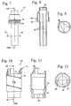
- FIGS. 7 to 25 show the components of the injection device 1 in detail.
- the driver 13 is shown.
- the driver 13 has at its distal end internal increments 35, which formed a at a nozzle 33 of the operating knob 8, in Fig. 5 engage behind the detent edge 34 and thereby connect the operating knob 8 in the axial direction with the driver 13.
- the sleeve-shaped carrier 13 has on its inner circumference in the exemplary embodiment four guide webs extending in the axial direction 40.
- the guide webs 40 are in Fig. 20 shown longitudinal grooves 64 of the Zuêtils 20 adapted and engage in this.
- the guide webs 40 make with the longitudinal grooves 64, the rotationally fixed connection between the driver 13 and Zudorfil 20 ago.
- the guide webs 40 are freely displaceable in the longitudinal grooves 64 in the direction of the longitudinal central axis 50 of the injection device 1.
- FIGS. 10 to 12 show the metering 16, which is also referred to as a scale tube or adjusting member.
- the metering member 16 is sleeve-shaped and has on its outer periphery an external thread 44.
- the external thread 44 is formed as a helical groove on the outer circumference of the metering 16.
- the metering member 16 carries a connecting contour 43, which is formed from hook and ramp-shaped elements, which produce a rotationally fixed connection with the adjusting sleeve 7.
- the metering member 16 has at its proximal end two guide grooves 45 which extend parallel to the longitudinal central axis 50.
- the guide grooves 45 are arranged opposite one another and cooperate with longitudinal webs 59 of the slider 19, which in the Figures 17 and 19 are shown.
- the longitudinal webs 59 which are guided in the guide grooves 45, results in a rotationally fixed connection between metering member 16 and slider 19.
- the longitudinal webs 59 are freely movable in the direction of the longitudinal central axis 50 in the guide grooves 45, so that the slide 19 relative to the metering 16 in the direction of the longitudinal central axis 50 is displaceable.
- the inner tube 17 is shown.
- the inner tube 17 is designed in two parts and consists of a proximal part 46 and a distal part 47, which are firmly connected to each other.
- the inner tube 17 can also be made in one piece. However, this results in a significantly more expensive production of the inner tube 17. To further simplify the production, it may be advantageous to form the inner tube 17 from more than two individual parts.
- an internal thread 49 is arranged, which is formed of a spirally extending on the inner circumference web.
- the internal thread 49 is formed by a single thread. It can be provided to form the internal thread 49 only by one or more sections of a thread.
- the internal thread 49 cooperates with the external thread 44 of the metering member 16 and causes an axial displacement of the metering member 16 upon rotation of the metering 16.
- an internal thread 51 is formed, which with a in Fig. 17 shown external thread 61 of the slider 19 cooperates.
- the internal thread 51 forms with the external thread 61, the third threaded connection 21.
- longitudinal webs 52 join.
- FIG. 15 shows, a total of four longitudinal webs 52 are provided, which are each arranged on both sides of an interruption 53.
- two interruptions 53 are provided, which are arranged opposite one another, that is to say at a distance from a circumferential angle of 180 ° to one another.
- a helical groove 54 is formed on the inner tube 17, which is formed as a depression in the wall of the inner tube 17.
- Another, not visible in the representation groove 54 is provided in the half-shell of the inner tube, which in Fig. 14 lies in front of the cutting plane.
- the spiral groove 54 extends in the embodiment over half a thread.
- the groove 54 may also extend over one or more threads, as in FIG Fig. 14 schematically indicated by the groove 54 ', which is shown in dashed lines.
- the proximal wall of the groove 54 forms a locking contour 55. Accordingly, a wall of the groove 54 'forms a locking contour 55'.
- the blocking contour 55 will be described in more detail below.
- Fig. 16 projects at the proximal end of the inner tube 17, a centering edge 58 in the proximal direction.
- the centering edge 58 protrudes into a proximal opening of the housing part 3 and ensures a tight fit of the inner tube 17 in the housing part 3.
- On the proximal side of the inner tube 17 also protrude support stub 56 in the proximal direction, at the proximal end radially inwardly projecting locking edges 57 are integrally formed.
- the latching edges 57 cooperate with a latching edge 79 of the piston rod ring 30, which in Fig. 5 is shown.
- the latching edge 79 provides with the locking edge 57 an axial securing for the piston rod ring 30. How Fig.
- the second compression spring 31 pushes the piston rod ring 30 in its proximal position until the locking edge 79 rests against the locking edge 57. In this position, the operator can rotate the housing part 3 relative to the piston rod ring 30 to move the metering piston 22 in the distal direction. This is provided when replacing a container for injection liquid.
- the slider 19 is shown in detail. At its distal end, the slider 19 has the locking edge 42. Like the Figures 17 and 18 show, the external thread 61 is formed in a ring land 60 which projects radially outward. Also, the slider 19 is formed substantially sleeve-shaped.
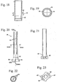
- FIGS. 20 to 23 show the Zuticianil 20.
- the Zuticianil 20 has two locking arms 66 which in Fig. 23 are shown.
- the latching arms 66 each have a detent 67 which faces radially outward.
- the latching arms 66 extend approximately in the circumferential direction and are designed to be resilient radially outward.
- Fig. 21 shows an internal thread 65 formed on the proximal end of the feed part 20, which cooperates with the metering piston 22.
- the internal thread 65 and the latching arms 65 are arranged in the same longitudinal section of the Zuudgeils 20.
- the piston rod 23 has an external thread 69 which cooperates with the internal thread 65 of the Zudorfils 20 and forms with this the first threaded connection 25.
- the piston rod 23 has flattenings 68, which secure the rotational position of the piston rod 23 with corresponding flats in a Fig. 5 shown opening 80 in the piston rod ring 30 cooperating
- the piston rod 23 has a mounting groove 70 on which the piston disc 24 is held.
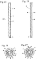
- Fig. 26 shows the arrangement of the Zuixieils 20 on the locking contour 55 in a locked position 74 of the control element 6 and Zuixieil 20.
- the detents 67 of the locking arms 66 are located on the locking contour 55 at. Since the notches 67 and the locking contour 55 overlap in the direction of the longitudinal central axis 50, the infeed part 20 can not be displaced in the proximal direction.
- the blocking position 74 of the operating element 6 is given when an impermissible amount of injection liquid is set. The pressing out of an impermissible amount of injection liquid is structurally prevented by the blocking contour 55.
- the control element 6 and thus also the Zuixieil 20 further rotated so get the notches 67 after overcoming the longitudinal webs 52, which form the latching means 26 with the detents 67, in the range of interruptions 53.
- the blocking contour 55 is interrupted.
- the interruptions 53 are formed as parallel to the longitudinal central axis 50 extending longitudinal grooves.
- longitudinal ridges 52 are arranged on both sides, so that there is a defined locking position for the Zuixieil 20 in the in Fig. 27 shown injection position 73 results.
- injection position 73 the feed part 20 can be pressed in the proximal direction.
- the detents 67 slide between the longitudinal webs 52, which run parallel to the longitudinal central axis 50, in the proximal direction.
- the longitudinal webs 52 prevent the feed member 20 from rotating during the injection.
- the driver 13 is rotatably held in the housing 2 during the injection and can not rotate with the forces prevailing during the injection forces.
- control knob 8 Only when the control element 6 and thus also the Zuixieil 20 is in injection position 73, the control knob 8 can be moved from its proximal position 72 together with the adjusting sleeve 7, the metering piston 16, the slider 19 and the Zuassiil 20 in the proximal direction , As a result, the piston rod 23 is moved in the proximal direction and injection liquid is squeezed out of the container.
- the actuating button 8 may indeed be pressed into the adjusting sleeve 7, a further displacement of the actuating knob 8 relative to the housing part 3 in the proximal direction is not possible, but is due to the locking contour 55 blocked, which blocks an axial displacement of the metering member 16, the slider 19 and the Zuixieils 20 via the notches 67 of the latching arms 66. This can ensure that only a structurally predetermined, permissible amount of injection liquid can be squeezed out of the container.
- an injection device 1 is shown in which only a single predetermined amount of injection liquid can be squeezed out of the container. This amount is reached when the control has been turned 180 °. It can however, also be provided that multiple injection positions 73 are possible, which are assigned to different amounts of injection liquid.
- the interruptions 53 at the points of the locking contour 55 which are associated with the desired, permissible quantities of injection liquid to provide.
Landscapes
- Health & Medical Sciences (AREA)
- Vascular Medicine (AREA)
- Engineering & Computer Science (AREA)
- Anesthesiology (AREA)
- Biomedical Technology (AREA)
- Heart & Thoracic Surgery (AREA)
- Hematology (AREA)
- Life Sciences & Earth Sciences (AREA)
- Animal Behavior & Ethology (AREA)
- General Health & Medical Sciences (AREA)
- Public Health (AREA)
- Veterinary Medicine (AREA)
- Infusion, Injection, And Reservoir Apparatuses (AREA)
Description
Die Erfindung betrifft ein Injektionsgerät der im Oberbegriff des Anspruchs 1 angegebenen Gattung.The invention relates to an injection device of the type specified in the preamble of
Aus der
Bei dem in der
Damit der Bedienknopf aus einer Zwischenposition selbsttätig und sicher in eine Rastposition springt, muss die Rastung hinreichend stark sein, und die radialen Rastpositionen müssen hinreichend nahe beieinander liegen. Die Stärke der Rastung beeinflusst jedoch das Drehmoment, das der Anwender aufwenden muss, um den Bedienknopf zu drehen und die Dosis einzustellen. Der konstruktiv mögliche Abstand der Rastpositionen ist weitgehend vorgegeben und kann nur in engen Grenzen auf den Anwendungsfall angepasst werden.Thus, the control knob automatically and safely jumps from an intermediate position in a detent position, the detent must be sufficiently strong, and the radial detent positions must be sufficiently close to each other. However, the strength of the detent affects the torque that the user must use to turn the control knob and adjust the dose. The constructive possible distance of the locking positions is largely predetermined and can be adapted only within narrow limits to the application.
Der Erfindung liegt die Aufgabe zugrunde, ein Injektionsgerät der gattungsgemäßen Art zu schaffen, bei dem nur vorgegebene Mengen von Injektionsflüssigkeit aus dem Behälter ausgepresst werden können und das eine gute Anpassung auf den gewünschten Anwendungsfall erlaubt.The invention has for its object to provide an injection device of the generic type, in which only predetermined amounts of injection liquid can be pressed out of the container and that allows a good adaptation to the desired application.
Diese Aufgabe wird durch ein Injektionsgerät mit den Merkmalen des Anspruchs 1 gelöst.This object is achieved by an injection device having the features of
Das Injektionsgerät besitzt ein Zustellteil, das beim Einstellen der auszupressenden Menge an Injektionsflüssigkeit in distaler Richtung bewegt und gleichzeitig um die Längsmittelachse gedreht wird. Beim Auspressen der Injektionsflüssigkeit bewegt sich das Zustellteil in Richtung der Längsmittelachse in proximaler Richtung, dreht sich gegenüber dem Gehäuse jedoch nicht. Um sicherzustellen, dass nur konstruktiv vorgegebene, zulässige Mengen an Injektionsflüssigkeit ausgepresst werden können, ist eine Sperrkontur vorgesehen, die mit dem Zustellteil zusammenwirkt. Die Sperrkontur stellt sicher, dass das Zustellteil nur in konstruktiv vorgegebenen Stellungen in Richtung der Längsmittelachse bewegt werden kann, ohne sich dabei gegenüber dem Gehäuse zu drehen. Die Sperrkontur verläuft dabei spiralförmig um die Längsmittelachse des Injektionsgeräts. Der Verlauf der Sperrkontur entspricht dabei der Bewegung des Zustellteils, so dass das Zustellteil bei seiner schraubenlinienförmigen Bewegung in distaler Richtung, die das Zustellteil beim Einstellen der auszupressenden Menge an Injektionsflüssigkeit ausführt, an der Sperrkontur anliegt. Durch die Unterbrechung der Sperrkontur wird ein Auspressen von Injektionsflüssigkeit ermöglicht. Die Injektionsflüssigkeit kann dabei nur in Mengeneinheiten abgegeben werden, die der Lage der Unterbrechung der Sperrkontur zugeordnet sind. Dabei kann nur eine einzige Unterbrechung der Sperrkontur vorgesehen sein. Es können jedoch auch mehrere Unterbrechungen der Sperrkontur vorgesehen sein, die vorteilhaft einen konstanten Winkelabstand zueinander um die Längsmittelachse besitzen. So können beispielsweise zwei Unterbrechungen an der Sperrkontur vorgesehen sein, die um 180° um die Längsmittelachse zueinander versetzt sind. Auch vier jeweils um 90° zueinander beabstandete Unterbrechungen können vorteilhaft sein. Die Anzahl der Unterbrechungen ist abhängig vom Anwendungsfall. Die Sperrkontur erstreckt sich vorteilhaft von der Position, in der das Zustellteil vor dem Einstellen der Dosis steht, bis zu der Position, in der sich das Zustellteil befindet, wenn die maximal mögliche Dosis eingestellt ist. Dadurch, dass die Sperrkontur unabhängig von Raststellungen des Bedienelements ist, kann eine gewünschte Raststärke und ein gewünschter Rastabstand unabhängig von den Mengeneinheiten an Injektionsflüssigkeit, die ausgepresst werden können, vorgesehen werden. Die Bedieneigenschaften des Injektionsgeräts sind dadurch weitgehend unabhängig von den injizierbaren Flüssigkeitsmengen konstruktiv einstellbar.The injection device has a feed part which moves in the distal direction when adjusting the amount of injection liquid to be squeezed out and at the same time is rotated about the longitudinal central axis. When the injection liquid is pressed out, the feed part moves in the direction of the longitudinal central axis in the proximal direction, but does not rotate relative to the housing. To ensure that only constructively predetermined, permissible quantities of injection liquid can be pressed out, a blocking contour is provided which interacts with the delivery part. The locking contour ensures that the Zustellteil can only be moved in structurally predetermined positions in the direction of the longitudinal central axis, without thereby rotate relative to the housing. The blocking contour runs in a spiral around the longitudinal central axis of the injection device. The course of the locking contour corresponds to the movement of the Zustellteils, so that the Zustellteil rests in its helical movement in the distal direction, which executes the feed part in adjusting the amount of injection liquid to be squeezed out of the locking contour. By interrupting the locking contour, a squeezing of injection liquid is made possible. The injection liquid can be dispensed only in units of units, which are assigned to the position of the interruption of the locking contour. In this case, only a single interruption of the locking contour can be provided. However, it can also be provided several interruptions of the locking contour, which advantageously have a constant angular distance from one another about the longitudinal center axis. For example, two Interruptions may be provided on the locking contour, which are offset by 180 ° about the longitudinal center axis to each other. Also, four each spaced by 90 ° interruptions may be advantageous. The number of interruptions depends on the application. Advantageously, the blocking contour extends from the position in which the delivery part stands before setting the dose up to the position in which the delivery part is located when the maximum possible dose has been set. Characterized in that the locking contour is independent of locking positions of the operating element, a desired locking force and a desired locking distance can be provided independently of the units of quantity of injection liquid that can be pressed. The operating properties of the injection device are thereby largely structurally independent of the injectable quantities of liquid.
Die "proximale Richtung" bezeichnet dabei die Injektionsrichtuhg, also in Richtung zu einer Aufnahme für die Injektionsnadel hin bzw. die Richtung, in der die Injektionsflüssigkeit aus dem Behälter ausgepresst wird. Die "distale Richtung" bezeichnet die entgegengesetzte Richtung, also von der Injektionsnadel weg. Das distale Ende des Injektionsgeräts ist das der Injektionsnadel abgewandt liegende Ende. Mit "proximal" wird die Seite des Injektionsgeräts bezeichnet, die bei einer Injektion der Einstichstelle zugewandt liegt und mit "distal" die Seite, die der Einstichstelle abgewandt liegt.The "proximal direction" designates the injection direction, ie in the direction of a receptacle for the injection needle or the direction in which the injection fluid is pressed out of the container. The "distal direction" refers to the opposite direction, ie away from the injection needle. The distal end of the injection device is the end facing away from the injection needle. "Proximal" refers to the side of the injection device that faces the puncture site during an injection and "distal" to the side away from the puncture site.
Das Bedienelement ist beim Einstellen der auszupressenden Menge an Injektionsflüssigkeit vorteilhaft in mindestens eine Injektionsstellung, in der eine zulässige Menge an Injektionsflüssigkeit eingestellt ist, und in mindestens eine Sperrstellung, in der eine unzulässige Menge an Injektionsflüssigkeit eingestellt ist, stellbar. In Sperrstellung liegt das Zustellteil vorteilhaft mit einem Sperrelement an der Sperrkontur an. Das Sperrelement und die Sperrkontur überlappen sich in axialer Richtung und verhindern so eine Bewegung des Zustellteils in Richtung der Längsmittelachse in proximaler Richtung. In Injektionsstellung ist das Sperrelement vorteilhaft an der distalen Seite der Unterbrechung der Sperrkontur angeordnet. Die Unterbrechung ist so ausgebildet, dass sie sich in axialer Richtung des Injektionsgeräts nicht mit dem Sperrelement überlappt, so dass die Bewegung des Zustellteils mit dem Sperrelement in proximaler Richtung im Bereich der Unterbrechung nicht behindert wird.When setting the amount of injection liquid to be squeezed out, the operating element is advantageously adjustable into at least one injection position in which an admissible quantity of injection liquid is set and in at least one blocking position in which an impermissible quantity of injection liquid is set. In the blocking position, the Zustellteil is advantageous with a locking element on the locking contour. The blocking element and the locking contour overlap in the axial direction and thus prevent a movement of the Zustellteils in the direction of the longitudinal central axis in the proximal direction. In the injection position, the blocking element is advantageously arranged on the distal side of the interruption of the blocking contour. The break is designed to be does not overlap in the axial direction of the injection device with the blocking element, so that the movement of the Zustellteils with the blocking element in the proximal direction in the region of the interruption is not hindered.
Vorteilhaft besitzt das Injektionsgerät eine Rasteinrichtung, die in Injektionsstellung einrastet und die zwischen Zustellteil und Gehäuse wirkt. Dadurch wird dem Bediener angezeigt, wann die zulässige Injektionsstellung erreicht ist. Durch die Ausbildung der Rasteinrichtung zwischen Zustellteil und Gehäuse wird ein einfacher Aufbau erreicht. Die Rasteinrichtung ist dadurch nur beim Einstellen der auszupressenden Menge an Injektionsflüssigkeit, nicht jedoch beim Injektionsvorgang aktiv. Dadurch kann die für den Injektionsvorgang benötigte Kraft gering gehalten werden. Es kann jedoch vorteilhaft sein, eine beim Injektionsvorgang wirkende Rasteinrichtung vorzusehen. Vorteilhaft besitzt das Zustellteil mindestens einen Rastarm, der an der Sperrkontur anliegt und das Sperrelement bildet. Das Injektionsgerät besitzt vorteilhaft mindestens eine Rasterhöhung, die in Umfangsrichtung benachbart zu der Unterbrechung der Sperrkontur angeordnet ist und die mit dem Rastarm die Rasteinrichtung bildet. Um sicherzustellen, dass sich das Zustellteil beim Injektionsvorgang nicht gegenüber dem Gehäuse drehen kann, ist vorgesehen, dass das Injektionsgerät eine Längsführung besitzt, die das Zustellteil bei seiner Bewegung in proximaler Richtung drehfest mit dem Gehäuse verbindet. Eine einfache Gestaltung ergibt sich, wenn das Injektionsgerät mindestens einen Längssteg besitzt, der parallel zur Längsmittelachse des Injektionsgeräts verläuft und der die Rasterhöhung und die Längsführung für den Rastarm bildet. Vorteilhaft sind in Umfangsrichtung beidseitig zu der Unterbrechung Längsführungen angeordnet, so dass die Injektionsstellung in beiden Drehrichtungen als Rastposition definiert ist.Advantageously, the injection device has a latching device which engages in the injection position and which acts between the Zustellteil and housing. This will indicate to the operator when the allowable injection position has been reached. The design of the locking device between the Zustellteil and housing a simple structure is achieved. The latching device is thereby only active when setting the amount of injection liquid to be pressed out, but not during the injection process. As a result, the force required for the injection process can be kept low. However, it may be advantageous to provide a locking device acting during the injection process. Advantageously, the Zustellteil has at least one latching arm, which bears against the locking contour and forms the blocking element. The injection device advantageously has at least one grid elevation, which is arranged in the circumferential direction adjacent to the interruption of the blocking contour and which forms the latching device with the latching arm. To ensure that the Zustellteil can not rotate relative to the housing during the injection process, it is provided that the injection device has a longitudinal guide which rotatably connects the Zustellteil during its movement in the proximal direction with the housing. A simple design results when the injection device has at least one longitudinal ridge which runs parallel to the longitudinal central axis of the injection device and which forms the grid elevation and the longitudinal guide for the latching arm. Longitudinal guides are advantageously arranged in the circumferential direction on both sides of the interruption, so that the injection position is defined as a latching position in both directions of rotation.
Die Drehbewegung des Zustellteils beim Einstellen der auszupressenden Menge an Injektionsflüssigkeit, die sich aufgrund der drehfesten Verbindung mit dem vom Bediener zu drehenden Bedienelement ergibt, bewirkt vorteilhaft über eine erste Gewindeverbindung die axiale Bewegung des Zustellteils. Das Zustellteil wird dabei um einen ersten Stellweg in distaler Richtung verschoben. Die erste Gewindeverbindung umfasst vorteilhaft ein Innengewinde des Zustellteils, das mit einem Außengewinde eines drehfest mit dem Gehäuse verbundenen Dosierkolbens zusammenwirkt. Da sowohl das Zustellteil als auch der Dosierkolben beim Auspressen der Injektionsflüssigkeit aus dem Behälter drehfest im Gehäuse gehalten sind, stellt die erste Gewindeverbindung beim Auspressen der Injektionsflüssigkeit eine feste Kopplung zwischen Zustellteil und Dosierkolben dar, über die die axiale Bewegung des Zustellteils in proximaler Richtung auf den Dosierkolben übertragen wird.The rotational movement of the Zustellteils when adjusting the amount of injection liquid to be squeezed, which results from the rotationally fixed connection with the operator to be rotated control, advantageously causes the first axial connection of the feed part via a first threaded connection. The delivery part will be one first travel displaced in the distal direction. The first threaded connection advantageously comprises an internal thread of the Zustellteils, which cooperates with an external thread of a rotatably connected to the housing metering. Since both the infeed part and the metering piston are non-rotatably held in the housing when the injection liquid is pressed out of the container, the first threaded connection when the injection liquid is pressed out constitutes a firm coupling between the infeed part and the metering piston, via which the axial movement of the infeed part in the proximal direction Metering piston is transmitted.
Die distale Bewegung des Bedienelements beim Einstellen der auszupressenden Menge an Injektionsflüssigkeit wird vorteilhaft über eine zweite Gewindeverbindung bewirkt.The distal movement of the operating element when adjusting the amount of injection liquid to be squeezed out is advantageously effected via a second threaded connection.
Das Bedienelement ist vorteilhaft mehrteilig ausgebildet und besitzt einen Betätigungsknopf und eine Stellhülse. Der Betätigungsknopf ist vorteilhaft über einen Mitnehmer mit dem Zustellteil verbunden. Die Stellhülse ist insbesondere fest mit dem Dosierorgan verbunden. Der Betätigungsknopf kann vorteilhaft gegenüber der Stellhülse zwischen einer ersten, distalen Position und einer zweiten, proximalen Position verschoben werden. Der Betätigungsknopf ist insbesondere über eine Kupplung mit der Stellhülse verbunden, wobei die Kupplung in der ersten, distalen Position des Betätigungsknopfs eine drehfeste Verbindung zwischen Mitnehmer und Stellhülse herstellt und in der zweiten, proximalen Position des Betätigungsknopfs eine Drehung der Stellhülse gegenüber dem Mitnehmer zulässt Der Betätigungsknopf ist insbesondere in Richtung auf seine distale Position gefedert, so dass der Bedienknopf in seiner distalen Position steht, wenn der Bediener den Bedienknopf nicht in proximale Richtung drückt. In der ersten, distalen Position befindet sich der Bedienknopf beim Einstellen der auszupressenden Menge an Injektionsflüssigkeit. In dieser Position des Betätigungsknopfs werden Stellhülse und Mitnehmer vom Bediener gemeinsam gedreht. Dabei drehen sich auch das Dosierorgan und das Zustellteil. In der zweiten, proximalen Position des Betätigungsknopfs kann sich die Stellhülse gegenüber dem Mitnehmer drehen. Diese Position des Betätigungsknopfs wird erreicht, wenn der Bediener den Betätigungsknopf in proximale Richtung drückt, um eine Injektion auszuführen.The control is advantageously designed in several parts and has an operating knob and a control sleeve. The actuating knob is advantageously connected via a driver with the Zustellteil. The adjusting sleeve is in particular firmly connected to the dosing. The actuating button can advantageously be moved relative to the adjusting sleeve between a first, distal position and a second, proximal position. The actuating knob is in particular connected via a coupling with the adjusting sleeve, wherein the coupling in the first, distal position of the actuating knob produces a rotationally fixed connection between the driver and the adjusting sleeve and in the second, proximal position of the actuating knob allows rotation of the adjusting sleeve relative to the driver is sprung in particular towards its distal position, so that the control knob is in its distal position when the operator does not press the control knob in the proximal direction. In the first, distal position, the control knob is in adjusting the amount of injection fluid to be squeezed out. In this position of the operating knob adjusting sleeve and driver are rotated together by the operator. The dosing element and the infeed part also rotate. In the second, proximal position of the actuating knob, the adjusting sleeve can rotate relative to the driver. These Position of the actuation button is achieved when the operator presses the actuation button in the proximal direction to perform an injection.
Das Dosierorgan ist vorteilhaft über die zweite Gewindeverbindung mit dem Gehäuse verbunden. Die Drehbewegung des Dosierorgans bewirkt insbesondere eine Bewegung des Dosierorgans und des Bedienelements in distaler Richtung um einen zweiten Stellweg. Beim Einstellen der auszupressenden Menge an Injektionsflüssigkeit bewegt sich das Bedienelement demnach in distaler Richtung. Das Dosierorgan bewegt sich entlang einer Schraubenlinie in distaler Richtung aus dem Gehäuse. Der zweite Stellweg ist dabei vorteilhaft größer als der erste Stellweg. Dadurch, dass der Stellweg für das Bedienelement deutlich größer als der Stellweg des Zustellteils ist, wird zum Auspressen der Injektionsflüssigkeit nur eine verringerte Kraft benötigt. Gleichzeitig ist für den Bediener aufgrund des großen Wegs des Bedienelements einfach erkennbar, ob die Injektionsflüssigkeit bereits ausgepresst wurde oder nicht.The dosing is advantageously connected via the second threaded connection with the housing. The rotational movement of the dosing causes in particular a movement of the metering and the control element in the distal direction by a second travel. When adjusting the amount of injection liquid to be squeezed, the operating element therefore moves in the distal direction. The dosing moves along a helix in the distal direction of the housing. The second travel is advantageously greater than the first travel. Characterized in that the travel for the control element is significantly greater than the travel of the Zustellteils, only a reduced force is required to squeeze the injection liquid. At the same time, it is easily recognizable to the operator, due to the long travel of the operating element, whether or not the injection liquid has already been pressed out.
Vorteilhaft besitzt das Injektionsgerät einen Schieber, der ein Gewinde einer dritten Gewindeverbindung trägt. Vorteilhaft ist der Schieber drehfest mit dem Dosierorgan verbunden und über die dritte Gewindeverbindung mit dem Gehäuse. Die dritte Gewindeverbindung bewirkt bei einer Drehbewegung des Dosierorgans und damit des Schiebers relativ zum Gehäuse eine Bewegung des Schiebers in distaler Richtung der Längsmittelachse um einen dritten Stellweg. Der dritte Stellweg ist dabei vorteilhaft genau so groß wie der erste Stellweg. Alternativ kann jedoch auch vorgesehen sein, dass der Schieber drehfest mit dem Gehäuse und über die dritte Gewindeverbindung mit dem Dosierorgan verbunden ist. Auch in diesem Fall bewirkt die dritte Gewindeverbindung bei einer Drehbewegung des Dosierorgans relativ zum Gehäuse eine dann allerdings rein axiale Bewegung des Schiebers in distaler Richtung der Längsmittelachse um einen dritten Stellweg. Auch hier ist der dritte Stellweg vorteilhaft genau so groß wie der erste Stellweg. Die dritte Gewindeverbindung besitzt eine Steigung, die bei Anordnung der dritten Gewindeverbindung zwischen Schieber und Gehäuse der Steigung der ersten Gewindeverbindung entspricht. Ist die dritte Gewindeverbindung zwischen dem Schieber und dem Mitriehmer ausgebildet, so entspricht die Steigung der dritten Gewindeverbindung der Differenz zwischen erster und zweiter Gewindeverbindung, so dass sich für den Schieber der gleiche Stellweg ergibt wie für das Zustellteil. Der Schieber besitzt vorteilhaft einen Mitnahmeabsatz, der mit einem Mitnahmeabsatz des Zustellteils zusammenwirkt und der eine axiale Bewegung des Schiebers in proximaler Richtung auf das Zustellteil überträgt. Über den Schieber und die dritte Gewindeverbindung bzw. die erste Gewindeverbindung und die dritte Gewindeverbindung erfolgt damit die Zustellbewegung zum Auspressen der auszupressenden Menge an Injektionsflüssigkeit.Advantageously, the injection device has a slider which carries a thread of a third threaded connection. Advantageously, the slide is rotatably connected to the metering and the third threaded connection with the housing. The third threaded connection causes a rotational movement of the metering and thus the slider relative to the housing movement of the slider in the distal direction of the longitudinal central axis to a third travel. The third travel is advantageous just as large as the first travel. Alternatively, however, it can also be provided that the slide is connected in a rotationally fixed manner to the housing and via the third threaded connection to the metering element. Also in this case causes the third threaded connection with a rotational movement of the metering relative to the housing but then purely axial movement of the slider in the distal direction of the longitudinal central axis to a third travel. Again, the third travel is advantageously just as large as the first travel. The third threaded connection has a pitch, which in the arrangement of the third threaded connection between the slide and the housing of the slope of the first threaded connection equivalent. If the third threaded connection is formed between the slide and the carrier, then the pitch of the third threaded connection corresponds to the difference between the first and second threaded connections, so that the same travel results for the slide as for the infeed part. The slider advantageously has a driving shoulder, which cooperates with a driving shoulder of the Zustellteils and transmits an axial movement of the slider in the proximal direction to the Zustellteil. By means of the slide and the third threaded connection or the first threaded connection and the third threaded connection, the feed movement thus takes place for pressing out the quantity of injection liquid to be expelled.
Ein Ausführungsbeispiel der Erfindung wird im Folgenden anhand der Zeichnung erläutert. Es zeigen:
- Fig. 1
- eine Seitenansicht eines Injektionsgeräts,
- Fig. 2
- einen Schnitt entlang der Linie II-II in
Fig. 1 , - Fig. 3
- das Injektionsgerät aus
Fig. 1 nach dem Einstellen der auszupressenden Menge an Injektionsflüssigkeit, - Fig. 4
- einen Schnitt entlang der Linie IV-IV in
Fig. 3 , - Fig. 5
- eine vergrößerte Darstellung des distalen Gehäuseteils des Injektionsgeräts aus
Fig. 2 , - Fig. 6
- eine ausschnittsweise Schnittdarstellung des Injektionsgeräts aus
Fig. 4 im Bereich des Bedienelements nach dem Drücken des Betätigungsknopfs, - Fig. 7
- eine Seitenansicht des Mitnehmers des Injektionsgeräts,
- Fig. 8
- einen Schnitt entlang der Linie VIII-VIII in
Fig. 7 , - Fig. 9
- einen Schnitt entlang der Linie IX-IX in
Fig. 7 , - Fig. 10
- eine Seitenansicht des Dosierorgans des Injektionsgeräts,
- Fig. 11
- einen Schnitt entlang der Linie XI-XI in
Fig. 10 , - Fig. 12
- eine Seitenansicht des Dosierorgans in Richtung des Pfeils XII in
Fig. 10 , - Fig. 13
- eine Seitenansicht eines Innenrohrs des Injektionsgeräts,
- Fig. 14
- einen Schnitt entlang der Linie XIV-XIV in
Fig. 13 , - Fig. 15
- einen Schnitt entlang der Linie XV-XV in
Fig. 13 , - Fig. 16
- eine vergrößerte Darstellung der Einzelheit XVI in
Fig. 14 , - Fig. 17
- eine Seitenansicht des Schiebers des Injektionsgeräts,
- Fig. 18
- einen Schnitt entlang der Linie XVIII-XVIII in
Fig. 17 , - Fig. 19
- einen Schnitt entlang der Linie XIX-XIX in
Fig. 17 , - Fig. 20
- eine Seitenansicht des Zustellteils des Injektionsgeräts,
- Fig. 21
- einen Schnitt entlang der Linie XXI-XXI in
Fig. 20 , - Fig. 22
- einen Schnitt entlang der Linie XXII-XXII in
Fig. 20 , - Fig. 23
- eine Seitenansicht des Zustellteils in Richtung des Pfeils XXIII in
Fig. 20 , - Fig. 24
- eine Seitenansicht der Kolbenstange des Dosierkolbens des Injektionsgeräts,
- Fig. 25
- eine Seitenansicht in Richtung des Pfeils XXV in
Fig. 24 , - Fig. 26
- einen Schnitt durch das Innenrohr auf der Höhe der Linie XV-XV in
Fig. 13 mit darin angeordnetem Zustellteil in Sperrstellung des Bedienelements, - Fig. 27
- eine Schnittdarstellung entsprechend
Fig. 26 mit dem Zustellteil in Injektionsstellung des Bedienelements.
- Fig. 1
- a side view of an injection device,
- Fig. 2
- a section along the line II-II in
Fig. 1 . - Fig. 3
- the injection device off
Fig. 1 after adjusting the amount of injection liquid to be squeezed, - Fig. 4
- a section along the line IV-IV in
Fig. 3 . - Fig. 5
- an enlarged view of the distal housing part of the injection device
Fig. 2 . - Fig. 6
- a partial sectional view of the injection device
Fig. 4 in the area of the operating element after pressing the operating button, - Fig. 7
- a side view of the driver of the injection device,
- Fig. 8
- a section along the line VIII-VIII in
Fig. 7 . - Fig. 9
- a section along the line IX-IX in
Fig. 7 . - Fig. 10
- a side view of the metering of the injection device,
- Fig. 11
- a section along the line XI-XI in
Fig. 10 . - Fig. 12
- a side view of the dosing in the direction of arrow XII in
Fig. 10 . - Fig. 13
- a side view of an inner tube of the injection device,
- Fig. 14
- a section along the line XIV-XIV in
Fig. 13 . - Fig. 15
- a section along the line XV-XV in
Fig. 13 . - Fig. 16
- an enlarged view of detail XVI in
Fig. 14 . - Fig. 17
- a side view of the slide of the injection device,
- Fig. 18
- a section along the line XVIII-XVIII in
Fig. 17 . - Fig. 19
- a section along the line XIX-XIX in
Fig. 17 . - Fig. 20
- a side view of the delivery part of the injection device,
- Fig. 21
- a section along the line XXI-XXI in
Fig. 20 . - Fig. 22
- a section along the line XXII-XXII in
Fig. 20 . - Fig. 23
- a side view of the Zustellteils in the direction of arrow XXIII in
Fig. 20 . - Fig. 24
- a side view of the piston rod of the metering piston of the injection device,
- Fig. 25
- a side view in the direction of the arrow XXV in
Fig. 24 . - Fig. 26
- a section through the inner tube at the height of the line XV-XV in
Fig. 13 with arranged therein Zustellteil in locking position of the operating element, - Fig. 27
- a sectional view accordingly
Fig. 26 with the infeed part in injection position of the operating element.
Das in
Wie
Die Kolbenstange 23 ist drehfest in einem Kolbenstangenring 30 gehalten. Der Kolbenstangenring 30 ist axial verschiebbar im Injektionsgerät 1 angeordnet. In der in
Das Dosierorgan 16 ist über eine zweite Gewindeverbindung 18 mit dem Innenrohr 17 verbunden. Das Innenrohr 17 ist fest mit dem Gehäuseteil 3 verbunden. Das Innenrohr könnte auch einteilig mit dem Gehäuseteil 3 ausgebildet sein, allerdings wird dadurch die Herstellung des Injektionsgeräts 1 sehr aufwendig. Das Dosierorgan 16 ist drehfest und axial verschiebbar mit einem Schieber 19 verbunden, der ins Innere des Dosierorgans 16 ragt. Der Schieber 19 ist über eine dritte Gewindeverbindung 21 mit dem Innenrohr 17 verbunden. Zwischen dem Mitnehmer 13 und dem Dosierorgan 16 wirkt eine Druckfeder 15, die den Betätigungsknopf 8 in seine erste Position 71 drückt.The
Zum Einstellen der auszupressenden Menge an Injektionsflüssigkeit dreht der Bediener das Bedienelement 6, bis die gewünschte Dosis im Sichtfenster 9 erscheint. Dabei dreht sich die Stellhülse 7. Das drehfest mit der Stellhülse 7 verbundene Dosierorgan 16 dreht sich dadurch gegenüber dem oberen Gehäuseteil 3 und dem Innenrohr 17. Aufgrund seiner Drehbewegung wird das Dosierorgan 16 über die zweite Gewindeverbindung 18 in distaler Richtung, also in Richtung des Pfeils 75 verschoben. Das Bedienelement 6 und der axial fest mit dem Betätigungsknopf 8 des Bedienelements 6 verbundene Mitnehmer 13 bewegen sich mit dem Dosierorgan 16. Das Bedienelement 6, der Mitnehmer 13 und das Dosierorgan 16 bewegen sich gemeinsam in distaler Richtung und drehen sich dabei aufgrund der zweiten Gewindeverbindung 18 um die Längsmittelachse 50.To set the amount of injection liquid to be squeezed, the operator turns the
Über die drehfeste Verbindung zwischen Mitnehmer 13 und Zustellteil 20 wird auch das Zustellteil 20 gegenüber dem oberen Gehäuseteil 3 gedreht. Über die erste Gewindeverbindung 25 bewegt sich auch das Zustellteil 20 in distaler Richtung. Der Schieber 19 bewegt sich ebenfalls in distaler Richtung, da der Schieber 19 drehfest mit dem Dosierorgan 16 verbunden ist. Auch der Schieber 19 und das Zustellteil 20 bewegen sich mit einer kombinierten Dreh- und Längsbewegung, wobei der Weg, den Schieber 19 und Zustellteil 20 in Richtung der Längsmittelachse 50 zurücklegen, über die erste Gewindeverbindung 25 bzw. über die dritte Gewindeverbindung 21 festgelegt sind. Es kann auch vorgesehen sein, dass der Schieber 19 über eine dritte Gewindeverbindung mit dem Dosierorgan 16 verbunden ist und drehfest mit dem Zustellteil 20 verbunden ist.About the non-rotatable connection between the
Die
Die maximal einzustellende Menge an Injektionsflüssigkeit ist durch den Weg vorgegeben, den der Betätigungsknopf 6 und das Dosierorgan 16 sich in distaler Richtung bewegen können. Dieser Weg wird durch einen zwischen dem Dosierorgan 16 und dem Schieber 19 gebildeten Anschlag 27 (
Wie
Nach dem Einstellen der zu injizierenden Dosis kann eine Injektion ausgelöst werden. Hierzu wird der Betätigungsknopf 8 in Richtung des Pfeils 77 in
Die
Die
In den
Im distalen Teil 47 des Innenrohrs 17 ist ein Innengewinde 49 angeordnet, das aus einem spiralförmig am Innenumfang verlaufenden Steg gebildet ist. Das Innengewinde 49 ist durch einen einzigen Gewindegang gebildet. Es kann vorgesehen sein, das Innengewinde 49 nur durch einen oder mehrere Teilabschnitte eines Gewindegangs auszubilden. Das Innengewinde 49 wirkt mit dem Außengewinde 44 des Dosierorgans 16 zusammen und bewirkt eine axiale Verschiebung des Dosierorgans 16 bei einer Drehung des Dosierorgans 16. Im proximalen Teil 46 des Innenrohrs 17 ist ein Innengewinde 51 ausgebildet, das mit einem in
Am proximalen Ende des Innenraums des Innenrohrs 17, in distaler Richtung an den Anschlag 28 anschließend, ist eine spiralförmige Nut 54 am Innenrohr 17 ausgebildet, die als Vertiefung in der Wand des Innenrohrs 17 ausgebildet ist. Eine weitere, in der Darstellung nicht sichtbare Nut 54 ist in der Halbschale des Innenrohrs vorgesehen, die in
Wie
In den
Die
Wie die
Wird das Bedienelement 6 und damit auch das Zustellteil 20 weiter gedreht, so gelangen die Rasten 67 nach Überwinden der Längsstege 52, die die mit den Rasten 67 die Rasteinrichtung 26 bilden, in den Bereich von Unterbrechungen 53. An den Unterbrechungen 53 ist die Sperrkontur 55 unterbrochen. Die Unterbrechungen 53 sind als parallel zur Längsmittelachse 50 verlaufende Längsnuten ausgebildet. In Umfangsrichtung sind beidseitig der Unterbrechungen 53 Längsstege 52 angeordnet, so dass sich eine definierte Rastposition für das Zustellteil 20 in der in
Nur dann, wenn sich das Bedienelement 6 und damit auch das Zustellteil 20 in Injektionsstellung 73 befindet, kann der Bedienknopf 8 aus seiner proximalen Position 72 zusammen mit der Stellhülse 7, dem Dosierkolben 16, dem Schieber 19 und dem Zustellteil 20 in proximale Richtung verschoben werden. Dadurch wird die Kolbenstange 23 in proximale Richtung bewegt und Injektionsflüssigkeit aus dem Behälter ausgepresst. Befindet sich das Bedienelement 6 und damit das Zustellteil 20 in Sperrstellung 74, so kann der Betätigungsknopf 8 zwar in die Stellhülse 7 gedrückt werden, ein weiteres Verschieben des Betätigungsknopfs 8 gegenüber dem Gehäuseteil 3 in proximale Richtung ist jedoch nicht möglich, sondern wird aufgrund der Sperrkontur 55 gesperrt, die eine axiale Verschiebung des Dosierorgans 16, des Schiebers 19 und des Zustellteils 20 über die Rasten 67 der Rastarme 66 blockiert. Dadurch kann sichergestellt werden, dass nur eine konstruktiv vorgegebene, zulässige Menge an Injektionsflüssigkeit aus dem Behälter ausgepresst werden kann.Only when the
Im Ausführungsbeispiel ist ein Injektionsgerät 1 gezeigt, bei dem nur eine einzige vorgegebene Menge an Injektionsflüssigkeit aus dem Behälter ausgepresst werden kann. Diese Menge ist erreicht, wenn das Bedienelement um 180° gedreht wurde. Es kann jedoch auch vorgesehen sein, dass mehrere Injektionsstellungen 73 möglich sind, die unterschiedlichen Mengen an Injektionsflüssigkeit zugeordnet sind. Hierbei sind die Unterbrechungen 53 an den Stellen der Sperrkontur 55, die den gewünschten, zulässigen Mengen an Injektionsflüssigkeit zugeordnet sind, vorzusehen.In the exemplary embodiment, an
Claims (14)
- Injection device having a housing (2), in which a receiving area (5) for a container with injection liquid is formed, having an operating element (6) which can be rotated to set an amount of injection liquid to be expressed from the container and which moves upon rotation in the direction of a longitudinal middle axis (50) of the injection device (1) in the distal direction of the injection device (1) relative to the housing (2), wherein the operating element (6) is displaced to express injection liquid from the container in the direction of the longitudinal middle axis (50) in the proximal direction of the injection device (1), wherein the injection device (1) has a blocking part (20) which is connected rotationally securely to the operating element (6) upon adjustment of the amount of injection liquid to be expressed and is displaced in the direction of the longitudinal middle axis (50) in the distal direction and which, upon expression of injection liquid from the container, is rotationally securely connected to the housing (2) and displaced in the direction of the longitudinal middle axis (50) in the proximal direction,
characterised in that the injection device (1) has a blocking contour (55) extending spirally around the longitudinal middle axis (50), which blocking contour (55) cooperates with the blocking part (20) and which blocks a movement of the blocking part (20) in the proximal direction, wherein the blocking contour (55) has on at least one point an interruption (53) which enables a movement of the blocking part (20) in the direction of the longitudinal middle axis (50) in the proximal direction. - Injection device according to claim 1,
characterised in that the operating element (6), upon adjustment of the amount of injection liquid to be expressed, can be moved into at least one injection position (73), in which an admissible amount of injection liquid is set, and into at least one blocking position (74), in which an inadmissible amount of injection liquid is set, wherein the blocking part (20) lies against the blocking contour (55) in the blocking position (74) and is arranged on the distal side of the interruption (53) of the blocking contour (55) in the injection position (73). - Injection device according to claim 2,
characterised in that the injection device (1) has a detent means (26) which latches in the injection position (73) and which acts between the blocking part (20) and the housing (2). - Injection device according to claim 3,
characterised in that the blocking part (20) has at least one detent arm (66) which lies against the blocking contour (55), and the injection device (1) has, in the peripheral direction adjacent to the interruption (53) of the blocking contour (55), at least one raised detent area which forms the detent means (26) with the detent arm (66). - Injection device according to claim 4,
characterised in that the injection device has a longitudinal guide which connects the blocking part (20) upon movement thereof in the proximal direction rotationally securely to the housing (2). - Injection device according to claim 5,
characterised in that the injection device (1) has at least one longitudinal web (52) which extends parallel to the longitudinal middle axis (50) of the injection device (1), wherein the longitudinal web (52) forms the raised detent area and the longitudinal guide for the detent arm (66). - Injection device according to one of claims 1 to 6,
characterised in that the rotation movement of the blocking part (20), upon setting of the amount of injection liquid to be expressed, causes via a first threaded connection (25) the axial movement of the blocking part (20), wherein the blocking part (20) is displaced by a first displacement path (a) in the distal direction. - Injection device according to claim 7,
characterised in that the first threaded connection (25) comprises an internal thread (65) of the blocking part (20) which cooperates with an external thread (69) of a metering piston element (22) connected rotationally securely to the housing (2). - Injection device according to claim 7 or 8,
characterised in that the operating element (6) is formed in multiple parts and has an activating button (8) and an adjustment sleeve (7), wherein the activating button (8) is connected via an entrainment element (13) to the blocking part (20), and wherein the adjustment sleeve (7) is fixedly connected to a metering element (16). - Injection device according to claim 9,
characterised in that the activating button (8) is connected via a coupling (14) to the adjustment sleeve (7), wherein the coupling (14) produces, in a first, distal position (71) of the activating button (8), a rotationally secure connection between the entrainment element (13) and the adjustment sleeve (7), and, in a second, proximal position (72) of the activating button (8), enables a rotation of the adjustment sleeve (7) relative to the entrainment element (13). - Injection device according to claim 9 or 10,
characterised in that the metering element (16) is connected, via a second threaded connection (18), to the housing (2), wherein the rotation movement of the metering element (16) causes a movement of the metering element (16) and the operating element (6) in the distal direction by a second displacement path (b), wherein the second displacement path (b) is larger than the first displacement path (a). - Injection device according to one of claims 9 to 11,
characterised in that the injection device (1) has a slider element (19) which carries a thread of a third threaded connection (21), wherein the third threaded connection (21), upon a rotation movement of the slider element (19), causes a movement of the slider element (19) in the distal direction of the longitudinal middle axis (50) by a third displacement path (c) which corresponds to the first displacement path (a). - Injection device according to claim 12,
characterised in that the slider element (19) is rotationally securely connected to the metering element (16) and via the third threaded connection (21) to the housing (2). - Injection device according to claim 12 or 13,
characterised in that the slider element (19) has an entrainment section (62) which cooperates with an entrainment section (63) of the blocking part (20) and which transmits an axial movement of the slider element (19) in the proximal direction to the blocking part (20).
Applications Claiming Priority (2)
| Application Number | Priority Date | Filing Date | Title |
|---|---|---|---|
| DE202012001410U DE202012001410U1 (en) | 2012-02-10 | 2012-02-10 | injection device |
| PCT/EP2013/000358 WO2013117331A1 (en) | 2012-02-10 | 2013-02-06 | Injection device |
Publications (2)
| Publication Number | Publication Date |
|---|---|
| EP2812054A1 EP2812054A1 (en) | 2014-12-17 |
| EP2812054B1 true EP2812054B1 (en) | 2016-06-22 |
Family
ID=47714013
Family Applications (1)
| Application Number | Title | Priority Date | Filing Date |
|---|---|---|---|
| EP13704002.8A Not-in-force EP2812054B1 (en) | 2012-02-10 | 2013-02-06 | Injection device |
Country Status (6)
| Country | Link |
|---|---|
| US (1) | US20140350480A1 (en) |
| EP (1) | EP2812054B1 (en) |
| DE (1) | DE202012001410U1 (en) |
| DK (1) | DK2812054T3 (en) |
| ES (1) | ES2593044T3 (en) |
| WO (1) | WO2013117331A1 (en) |
Cited By (3)
| Publication number | Priority date | Publication date | Assignee | Title |
|---|---|---|---|---|
| US11969583B2 (en) | 2018-07-17 | 2024-04-30 | Medmix Switzerland Ag | Injection device with dose interruption fail safe |
| US11969584B2 (en) | 2017-07-13 | 2024-04-30 | Medmix Switzerland Ag | Injection device with flexible dose selection |
| EP4450100A1 (en) * | 2023-04-18 | 2024-10-23 | medmix Switzerland AG | Mechanism for an automatic medicament delivery device |
Families Citing this family (3)
| Publication number | Priority date | Publication date | Assignee | Title |
|---|---|---|---|---|
| US10099015B2 (en) * | 2013-04-10 | 2018-10-16 | Sanofi | Drive mechanism for a drug delivery device |
| CN115227910A (en) * | 2018-04-13 | 2022-10-25 | 迈德米斯瑞士股份公司 | Medicament delivery device |
| DE102019006327A1 (en) * | 2019-09-09 | 2021-03-11 | Drägerwerk AG & Co. KGaA | Metering device and method for setting a metering of a fluid |
Family Cites Families (3)
| Publication number | Priority date | Publication date | Assignee | Title |
|---|---|---|---|---|
| US9205197B2 (en) * | 2003-03-03 | 2015-12-08 | Sanofi-Aventis Deutschland Gmbh | Drug delivery device dose setting mechanism |
| DE20317377U1 (en) | 2003-11-03 | 2005-03-17 | B D Medico S A R L | injection device |
| JP5897016B2 (en) * | 2010-10-13 | 2016-03-30 | サノフィ−アベンティス・ドイチュラント・ゲゼルシャフト・ミット・ベシュレンクテル・ハフツング | Dose setting mechanism and method of using the same |
-
2012
- 2012-02-10 DE DE202012001410U patent/DE202012001410U1/en not_active Expired - Lifetime
-
2013
- 2013-02-06 EP EP13704002.8A patent/EP2812054B1/en not_active Not-in-force
- 2013-02-06 WO PCT/EP2013/000358 patent/WO2013117331A1/en active Application Filing
- 2013-02-06 ES ES13704002.8T patent/ES2593044T3/en active Active
- 2013-02-06 DK DK13704002.8T patent/DK2812054T3/en active
-
2014
- 2014-08-11 US US14/456,895 patent/US20140350480A1/en not_active Abandoned
Non-Patent Citations (1)
| Title |
|---|
| None * |
Cited By (3)
| Publication number | Priority date | Publication date | Assignee | Title |
|---|---|---|---|---|
| US11969584B2 (en) | 2017-07-13 | 2024-04-30 | Medmix Switzerland Ag | Injection device with flexible dose selection |
| US11969583B2 (en) | 2018-07-17 | 2024-04-30 | Medmix Switzerland Ag | Injection device with dose interruption fail safe |
| EP4450100A1 (en) * | 2023-04-18 | 2024-10-23 | medmix Switzerland AG | Mechanism for an automatic medicament delivery device |
Also Published As
| Publication number | Publication date |
|---|---|
| EP2812054A1 (en) | 2014-12-17 |
| DK2812054T3 (en) | 2016-09-12 |
| ES2593044T3 (en) | 2016-12-05 |
| US20140350480A1 (en) | 2014-11-27 |
| WO2013117331A1 (en) | 2013-08-15 |
| DE202012001410U1 (en) | 2013-05-13 |
Similar Documents
| Publication | Publication Date | Title |
|---|---|---|
| EP3284498B1 (en) | Injection device | |
| EP3102254B1 (en) | Injection device | |
| EP2812054B1 (en) | Injection device | |
| EP3102256B1 (en) | Injection device | |
| EP3355965B1 (en) | Autoinjector with metering device | |
| EP3102257B1 (en) | Injection device | |
| WO2013117332A1 (en) | Injection device | |
| DE102005060928A1 (en) | Injection device with axially overlapping metering or display element | |
| WO1997036626A1 (en) | Injection device | |
| EP3355967B1 (en) | Injection apparatus | |
| WO2009062686A1 (en) | Injector comprising an actuator-activated coupling | |
| DE20112501U1 (en) | Locking lock for connecting housing parts of an injection or infusion device | |
| EP1838368B1 (en) | Injection device with a dosing mechanism | |
| EP3355963B1 (en) | Injection apparatus | |
| WO2017054916A1 (en) | Injection apparatus | |
| DE20302008U1 (en) | Application device for applying a liquid, gel-like or pasty cosmetic medium to the skin | |
| EP3365048B1 (en) | Injection device |
Legal Events
| Date | Code | Title | Description |
|---|---|---|---|
| PUAI | Public reference made under article 153(3) epc to a published international application that has entered the european phase |
Free format text: ORIGINAL CODE: 0009012 |
|
| 17P | Request for examination filed |
Effective date: 20140719 |
|
| AK | Designated contracting states |
Kind code of ref document: A1 Designated state(s): AL AT BE BG CH CY CZ DE DK EE ES FI FR GB GR HR HU IE IS IT LI LT LU LV MC MK MT NL NO PL PT RO RS SE SI SK SM TR |
|
| AX | Request for extension of the european patent |
Extension state: BA ME |
|
| DAX | Request for extension of the european patent (deleted) | ||
| RAP1 | Party data changed (applicant data changed or rights of an application transferred) |
Owner name: HASELMEIER AG |
|
| GRAP | Despatch of communication of intention to grant a patent |
Free format text: ORIGINAL CODE: EPIDOSNIGR1 |
|
| INTG | Intention to grant announced |
Effective date: 20151029 |
|
| GRAS | Grant fee paid |
Free format text: ORIGINAL CODE: EPIDOSNIGR3 |
|
| GRAP | Despatch of communication of intention to grant a patent |
Free format text: ORIGINAL CODE: EPIDOSNIGR1 |
|
| INTG | Intention to grant announced |
Effective date: 20160316 |
|
| GRAA | (expected) grant |
Free format text: ORIGINAL CODE: 0009210 |
|
| AK | Designated contracting states |
Kind code of ref document: B1 Designated state(s): AL AT BE BG CH CY CZ DE DK EE ES FI FR GB GR HR HU IE IS IT LI LT LU LV MC MK MT NL NO PL PT RO RS SE SI SK SM TR |
|
| REG | Reference to a national code |
Ref country code: GB Ref legal event code: FG4D Free format text: NOT ENGLISH |
|
| REG | Reference to a national code |
Ref country code: CH Ref legal event code: EP |
|
| REG | Reference to a national code |
Ref country code: IE Ref legal event code: FG4D Free format text: LANGUAGE OF EP DOCUMENT: GERMAN |
|
| REG | Reference to a national code |
Ref country code: AT Ref legal event code: REF Ref document number: 807291 Country of ref document: AT Kind code of ref document: T Effective date: 20160715 |
|
| REG | Reference to a national code |
Ref country code: CH Ref legal event code: NV Representative=s name: ISLER AND PEDRAZZINI AG, CH |
|
| REG | Reference to a national code |
Ref country code: DE Ref legal event code: R096 Ref document number: 502013003459 Country of ref document: DE |
|
| REG | Reference to a national code |
Ref country code: NL Ref legal event code: FP |
|
| REG | Reference to a national code |
Ref country code: DK Ref legal event code: T3 Effective date: 20160905 |
|
| REG | Reference to a national code |
Ref country code: SE Ref legal event code: TRGR |
|
| REG | Reference to a national code |
Ref country code: LT Ref legal event code: MG4D |
|
| PG25 | Lapsed in a contracting state [announced via postgrant information from national office to epo] |
Ref country code: FI Free format text: LAPSE BECAUSE OF FAILURE TO SUBMIT A TRANSLATION OF THE DESCRIPTION OR TO PAY THE FEE WITHIN THE PRESCRIBED TIME-LIMIT Effective date: 20160622 Ref country code: LT Free format text: LAPSE BECAUSE OF FAILURE TO SUBMIT A TRANSLATION OF THE DESCRIPTION OR TO PAY THE FEE WITHIN THE PRESCRIBED TIME-LIMIT Effective date: 20160622 |
|
| REG | Reference to a national code |
Ref country code: NO Ref legal event code: T2 Effective date: 20160622 |
|
| PG25 | Lapsed in a contracting state [announced via postgrant information from national office to epo] |
Ref country code: HR Free format text: LAPSE BECAUSE OF FAILURE TO SUBMIT A TRANSLATION OF THE DESCRIPTION OR TO PAY THE FEE WITHIN THE PRESCRIBED TIME-LIMIT Effective date: 20160622 Ref country code: LV Free format text: LAPSE BECAUSE OF FAILURE TO SUBMIT A TRANSLATION OF THE DESCRIPTION OR TO PAY THE FEE WITHIN THE PRESCRIBED TIME-LIMIT Effective date: 20160622 Ref country code: GR Free format text: LAPSE BECAUSE OF FAILURE TO SUBMIT A TRANSLATION OF THE DESCRIPTION OR TO PAY THE FEE WITHIN THE PRESCRIBED TIME-LIMIT Effective date: 20160923 Ref country code: RS Free format text: LAPSE BECAUSE OF FAILURE TO SUBMIT A TRANSLATION OF THE DESCRIPTION OR TO PAY THE FEE WITHIN THE PRESCRIBED TIME-LIMIT Effective date: 20160622 |
|
| REG | Reference to a national code |
Ref country code: ES Ref legal event code: FG2A Ref document number: 2593044 Country of ref document: ES Kind code of ref document: T3 Effective date: 20161205 |
|
| PG25 | Lapsed in a contracting state [announced via postgrant information from national office to epo] |
Ref country code: IS Free format text: LAPSE BECAUSE OF FAILURE TO SUBMIT A TRANSLATION OF THE DESCRIPTION OR TO PAY THE FEE WITHIN THE PRESCRIBED TIME-LIMIT Effective date: 20161022 Ref country code: CZ Free format text: LAPSE BECAUSE OF FAILURE TO SUBMIT A TRANSLATION OF THE DESCRIPTION OR TO PAY THE FEE WITHIN THE PRESCRIBED TIME-LIMIT Effective date: 20160622 Ref country code: EE Free format text: LAPSE BECAUSE OF FAILURE TO SUBMIT A TRANSLATION OF THE DESCRIPTION OR TO PAY THE FEE WITHIN THE PRESCRIBED TIME-LIMIT Effective date: 20160622 Ref country code: RO Free format text: LAPSE BECAUSE OF FAILURE TO SUBMIT A TRANSLATION OF THE DESCRIPTION OR TO PAY THE FEE WITHIN THE PRESCRIBED TIME-LIMIT Effective date: 20160622 Ref country code: SK Free format text: LAPSE BECAUSE OF FAILURE TO SUBMIT A TRANSLATION OF THE DESCRIPTION OR TO PAY THE FEE WITHIN THE PRESCRIBED TIME-LIMIT Effective date: 20160622 |
|
| PG25 | Lapsed in a contracting state [announced via postgrant information from national office to epo] |
Ref country code: PL Free format text: LAPSE BECAUSE OF FAILURE TO SUBMIT A TRANSLATION OF THE DESCRIPTION OR TO PAY THE FEE WITHIN THE PRESCRIBED TIME-LIMIT Effective date: 20160622 Ref country code: SM Free format text: LAPSE BECAUSE OF FAILURE TO SUBMIT A TRANSLATION OF THE DESCRIPTION OR TO PAY THE FEE WITHIN THE PRESCRIBED TIME-LIMIT Effective date: 20160622 Ref country code: PT Free format text: LAPSE BECAUSE OF FAILURE TO SUBMIT A TRANSLATION OF THE DESCRIPTION OR TO PAY THE FEE WITHIN THE PRESCRIBED TIME-LIMIT Effective date: 20161024 |
|
| REG | Reference to a national code |
Ref country code: DE Ref legal event code: R097 Ref document number: 502013003459 Country of ref document: DE |
|
| PLBE | No opposition filed within time limit |
Free format text: ORIGINAL CODE: 0009261 |
|
| STAA | Information on the status of an ep patent application or granted ep patent |
Free format text: STATUS: NO OPPOSITION FILED WITHIN TIME LIMIT |
|
| 26N | No opposition filed |
Effective date: 20170323 |
|
| PG25 | Lapsed in a contracting state [announced via postgrant information from national office to epo] |
Ref country code: BE Free format text: LAPSE BECAUSE OF NON-PAYMENT OF DUE FEES Effective date: 20170228 |
|
| PG25 | Lapsed in a contracting state [announced via postgrant information from national office to epo] |
Ref country code: SI Free format text: LAPSE BECAUSE OF FAILURE TO SUBMIT A TRANSLATION OF THE DESCRIPTION OR TO PAY THE FEE WITHIN THE PRESCRIBED TIME-LIMIT Effective date: 20160622 |
|
| REG | Reference to a national code |
Ref country code: DE Ref legal event code: R119 Ref document number: 502013003459 Country of ref document: DE |
|
| REG | Reference to a national code |
Ref country code: DK Ref legal event code: EBP Effective date: 20170228 |
|
| REG | Reference to a national code |
Ref country code: NO Ref legal event code: MMEP |
|
| PG25 | Lapsed in a contracting state [announced via postgrant information from national office to epo] |
Ref country code: MC Free format text: LAPSE BECAUSE OF FAILURE TO SUBMIT A TRANSLATION OF THE DESCRIPTION OR TO PAY THE FEE WITHIN THE PRESCRIBED TIME-LIMIT Effective date: 20160622 |
|
| REG | Reference to a national code |
Ref country code: CH Ref legal event code: PL |
|
| REG | Reference to a national code |
Ref country code: SE Ref legal event code: EUG |
|
| REG | Reference to a national code |
Ref country code: NL Ref legal event code: MM Effective date: 20170301 |
|
| GBPC | Gb: european patent ceased through non-payment of renewal fee |
Effective date: 20170206 |
|
| PG25 | Lapsed in a contracting state [announced via postgrant information from national office to epo] |
Ref country code: CH Free format text: LAPSE BECAUSE OF NON-PAYMENT OF DUE FEES Effective date: 20170228 Ref country code: NO Free format text: LAPSE BECAUSE OF NON-PAYMENT OF DUE FEES Effective date: 20170228 Ref country code: LI Free format text: LAPSE BECAUSE OF NON-PAYMENT OF DUE FEES Effective date: 20170228 |
|
| REG | Reference to a national code |
Ref country code: IE Ref legal event code: MM4A |
|
| PG25 | Lapsed in a contracting state [announced via postgrant information from national office to epo] |
Ref country code: SE Free format text: LAPSE BECAUSE OF NON-PAYMENT OF DUE FEES Effective date: 20170207 Ref country code: NL Free format text: LAPSE BECAUSE OF NON-PAYMENT OF DUE FEES Effective date: 20170301 |
|
| REG | Reference to a national code |
Ref country code: FR Ref legal event code: ST Effective date: 20171031 |
|
| PG25 | Lapsed in a contracting state [announced via postgrant information from national office to epo] |
Ref country code: LU Free format text: LAPSE BECAUSE OF NON-PAYMENT OF DUE FEES Effective date: 20170206 |
|
| PG25 | Lapsed in a contracting state [announced via postgrant information from national office to epo] |
Ref country code: FR Free format text: LAPSE BECAUSE OF NON-PAYMENT OF DUE FEES Effective date: 20170228 Ref country code: DE Free format text: LAPSE BECAUSE OF NON-PAYMENT OF DUE FEES Effective date: 20170901 Ref country code: DK Free format text: LAPSE BECAUSE OF NON-PAYMENT OF DUE FEES Effective date: 20170228 |
|
| REG | Reference to a national code |
Ref country code: BE Ref legal event code: MM Effective date: 20170228 |
|
| PG25 | Lapsed in a contracting state [announced via postgrant information from national office to epo] |
Ref country code: GB Free format text: LAPSE BECAUSE OF NON-PAYMENT OF DUE FEES Effective date: 20170206 Ref country code: IE Free format text: LAPSE BECAUSE OF NON-PAYMENT OF DUE FEES Effective date: 20170206 Ref country code: IT Free format text: LAPSE BECAUSE OF NON-PAYMENT OF DUE FEES Effective date: 20170206 |
|
| REG | Reference to a national code |
Ref country code: ES Ref legal event code: FD2A Effective date: 20180626 |
|
| PG25 | Lapsed in a contracting state [announced via postgrant information from national office to epo] |
Ref country code: ES Free format text: LAPSE BECAUSE OF NON-PAYMENT OF DUE FEES Effective date: 20170207 |
|
| PG25 | Lapsed in a contracting state [announced via postgrant information from national office to epo] |
Ref country code: MT Free format text: LAPSE BECAUSE OF FAILURE TO SUBMIT A TRANSLATION OF THE DESCRIPTION OR TO PAY THE FEE WITHIN THE PRESCRIBED TIME-LIMIT Effective date: 20160622 |
|
| PG25 | Lapsed in a contracting state [announced via postgrant information from national office to epo] |
Ref country code: AL Free format text: LAPSE BECAUSE OF FAILURE TO SUBMIT A TRANSLATION OF THE DESCRIPTION OR TO PAY THE FEE WITHIN THE PRESCRIBED TIME-LIMIT Effective date: 20160622 |
|
| REG | Reference to a national code |
Ref country code: AT Ref legal event code: MM01 Ref document number: 807291 Country of ref document: AT Kind code of ref document: T Effective date: 20180206 |
|
| PG25 | Lapsed in a contracting state [announced via postgrant information from national office to epo] |
Ref country code: AT Free format text: LAPSE BECAUSE OF NON-PAYMENT OF DUE FEES Effective date: 20180206 |
|
| PG25 | Lapsed in a contracting state [announced via postgrant information from national office to epo] |
Ref country code: HU Free format text: LAPSE BECAUSE OF FAILURE TO SUBMIT A TRANSLATION OF THE DESCRIPTION OR TO PAY THE FEE WITHIN THE PRESCRIBED TIME-LIMIT; INVALID AB INITIO Effective date: 20130206 |
|
| PG25 | Lapsed in a contracting state [announced via postgrant information from national office to epo] |
Ref country code: BG Free format text: LAPSE BECAUSE OF FAILURE TO SUBMIT A TRANSLATION OF THE DESCRIPTION OR TO PAY THE FEE WITHIN THE PRESCRIBED TIME-LIMIT Effective date: 20160622 |
|
| PG25 | Lapsed in a contracting state [announced via postgrant information from national office to epo] |
Ref country code: CY Free format text: LAPSE BECAUSE OF FAILURE TO SUBMIT A TRANSLATION OF THE DESCRIPTION OR TO PAY THE FEE WITHIN THE PRESCRIBED TIME-LIMIT Effective date: 20160622 |
|
| PG25 | Lapsed in a contracting state [announced via postgrant information from national office to epo] |
Ref country code: MK Free format text: LAPSE BECAUSE OF FAILURE TO SUBMIT A TRANSLATION OF THE DESCRIPTION OR TO PAY THE FEE WITHIN THE PRESCRIBED TIME-LIMIT Effective date: 20160622 |
|
| PG25 | Lapsed in a contracting state [announced via postgrant information from national office to epo] |
Ref country code: TR Free format text: LAPSE BECAUSE OF NON-PAYMENT OF DUE FEES Effective date: 20170206 |