EP2811611A2 - Power supply apparatus and electronic apparatus having the same - Google Patents
Power supply apparatus and electronic apparatus having the same Download PDFInfo
- Publication number
- EP2811611A2 EP2811611A2 EP20140152403 EP14152403A EP2811611A2 EP 2811611 A2 EP2811611 A2 EP 2811611A2 EP 20140152403 EP20140152403 EP 20140152403 EP 14152403 A EP14152403 A EP 14152403A EP 2811611 A2 EP2811611 A2 EP 2811611A2
- Authority
- EP
- European Patent Office
- Prior art keywords
- power supply
- power
- power supplies
- switch
- supplies
- Prior art date
- Legal status (The legal status is an assumption and is not a legal conclusion. Google has not performed a legal analysis and makes no representation as to the accuracy of the status listed.)
- Granted
Links
Images




Classifications
-
- H—ELECTRICITY
- H02—GENERATION; CONVERSION OR DISTRIBUTION OF ELECTRIC POWER
- H02J—ELECTRIC POWER NETWORKS; CIRCUIT ARRANGEMENTS OR SYSTEMS FOR SUPPLYING OR DISTRIBUTING ELECTRIC POWER; SYSTEMS FOR STORING ELECTRIC ENERGY
- H02J7/00—Circuit arrangements for charging or discharging batteries or for supplying loads from batteries
-
- H—ELECTRICITY
- H02—GENERATION; CONVERSION OR DISTRIBUTION OF ELECTRIC POWER
- H02J—ELECTRIC POWER NETWORKS; CIRCUIT ARRANGEMENTS OR SYSTEMS FOR SUPPLYING OR DISTRIBUTING ELECTRIC POWER; SYSTEMS FOR STORING ELECTRIC ENERGY
- H02J7/00—Circuit arrangements for charging or discharging batteries or for supplying loads from batteries
- H02J7/34—Parallel operation in networks using both storage and other DC sources, e.g. providing buffering
Definitions
- Apparatuses and methods consistent with exemplary embodiments relate to a power supply apparatus and an electronic apparatus having the same. More particularly, apparatuses consistent with the exemplary embodiments relate to a power supply apparatus which supplies various power levels from a plurality of power supply sources by means of a switch, and an electronic apparatus having the same.
- a battery management system refers to a system that prevents overcharging or over discharging of a battery by monitoring the battery.
- a battery is, for example, a power supply source in an electronic apparatus.
- a BMS also increases energy efficiency and battery life by balancing voltages between battery cells.
- FIG. 1 is a block diagram of a power supply apparatus in a related-art battery management system.
- the related-art power supply apparatus 1 includes a power supply 10, a first converter 20, and a second converter 30.
- a power supply can be, for example, a device which provides electric power.
- the first converter 20 and the second converter 30 may be connected to a first element 50 and a second element 60, respectively.
- the first and second element could be, for example, a pre-amplifier and an amplifier, respectively.
- the power supply 10 may be implemented by using a single battery or a plurality of batteries. When the power supply 10 is implemented by using a plurality of batteries, the batteries are connected to one another in series or in parallel so that power is supplied to both the first converter 20 and the second converter 30.
- the first converter 20 and the second converter 30 each may raise or reduce power which is supplied to drive the first element 40 and the second element 60 appropriately. That is, since the power supplied by the power supply 10 has a fixed value, the first converter 20 and the second converter should adjust the fixed level of power supplied from the power supply 10, in order to drive the first element 50 and the second element 60 which are operated by different optimal levels of power.
- One or more exemplary embodiments may overcome the above disadvantages and other disadvantages not described above. However, it is understood that one or more exemplary embodiments are not required to overcome the disadvantages described above, and may not overcome any of the problems described above.
- One or more exemplary embodiments provide a power supply apparatus which supplies power of varying levels by connecting a plurality of power supplies in series or in parallel by using a switch, and an electronic apparatus having the same.
- a power supply apparatus including: a plurality of power supplies arranged as a single array; a switch disposed between the plurality of power supplies configured to control connection states of the plurality of power supplies; and a controller configured to control the switch to connect the plurality of power supplies in parallel when a first event requiring a voltage less than a predetermined reference voltage occurs, and configured to control the switch to connect the plurality of power supplies in series when a second event requiring a voltage exceeding the predetermined reference voltage occurs.
- voltages of the plurality of power supplies may be the same.
- the controller may control the switch to connect an anode of a first power supply of the plurality of power supplies and an anode of a second power supply of the plurality of power supplies, and controls the switch to connect a cathode of the first power supply and a cathode of the second power supply, such that the plurality of power supplies are connected to each other in parallel.
- the controller may control the switch to connect an anode of a first power supply of the plurality of power supplies and a cathode of a second power supply of the plurality of power supplies such that the plurality of power supplies are connected to each other in series.
- the power supply apparatus may include a plurality of power supply arrays, and an output terminal of a first power supply array of the plurality of power supply arrays may be connected to an input terminal of a second power supply array which is adjacent to the first power supply array.
- an electronic apparatus which is operable in a first mode and a second mode, the electronic apparatus including: a first element configured to be operated by a voltage less than a predetermined reference voltage in the first mode and the second mode; a second element configured to be operated by a voltage less than the predetermined reference voltage in the first mode, and configured to be operated by a voltage exceeding the predetermined reference voltage in the second mode; and a power supply apparatus configured to supply power to the first element and the second element, wherein the power supply apparatus includes: a plurality of power supplies arranged as a single array; a switch disposed between the plurality of power supplies and configured to control connection states of the plurality of power supplies; and a controller configured to control the switch to connect the plurality of power supplies in parallel when the electronic apparatus is operated in the first mode, and configured to connect the plurality of power supplies in series when the electronic apparatus is operated in the second mode.
- voltages of the plurality of power supplies may be the same.
- the electronic apparatus may further include a direct current to direct current (DC-to-DC) converter connected between the first element and one of the plurality of power supplies, and the DC-to-DC converter may reduce a voltage supplied to the first element when the electronic apparatus is operated in the second mode and thus the plurality of power supplies may be connected to one another in series.
- DC-to-DC direct current to direct current
- the power supply apparatus may include a plurality of power supply arrays including the plurality of power supplies and the switch, and an output terminal of a first power supply of the plurality of power supply arrays may be connected to an input terminal of a second power supply array of the plurality of power supply arrays which is adjacent to the first power supply array.
- the electronic apparatus may be implemented by using an audio apparatus, and the first element may be implemented by using a pre-amplifier and the second element may be implemented by using an amplifier.
- the first mode may be a mode in which an audio signal is output which is less than a predetermined level
- the second mode may be a mode in which an audio signal is output which exceeds the predetermined level.
- the power supply apparatus supplies power of varying levels from the plurality of power supplies.
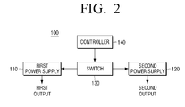
- FIG. 2 is a block diagram illustrating a power supply apparatus 100 according to an exemplary embodiment.
- a power supply apparatus 100 includes a first power supply 110 and a second power supply 120, a switch 130, and a controller 140.
- a first power supply 110 and a second power supply 120 includes a switch 130, and a controller 140.
- two power supplies are illustrated, however, the exemplary embodiment is not limited to two power supplies.
- the power supplies supply power to elements connected thereto.
- the supplied power may be direct current power or alternating current power.
- the power supplied to the elements may be supplied from the plurality of power supplies and each power supply may have an output terminal formed therein.
- the elements may include, for example, a pre-amplifier and an amplifier.
- the first output may be supplied to an element that is connected to the first power supply 110 through the output terminal formed in the first power supply 110
- the second output may be supplied to an element that is connected to the second power supply 120 through the output terminal formed in the second power supply 120.
- the power supply of the power supply apparatus 100 may include a plurality of power supplies other than two. In this case, the plurality of power supplies may be arranged as a single array.
- the switch 130 is disposed between the plurality of power supplies to control connection states of the plurality of power supplies. As shown in FIG. 2 , the switch 130 may be connected between the first power supply 110 and the second power supply 120. A level of power supplied by the first power supply 110 or the second power supply 120 may be changed by switching the switch 130.
- the controller 140 may be connected to the switch 130 and may receive an external signal.
- the external signal may be a signal that contains information on an optimal level of power that is required by an element which is connected to the power supply. Accordingly, a signal that contains information on an optimal level of power that is supplied by each of the plurality of power supplies may be input to the controller 140, and the controller 140 may control switching of the switch 130 according to the input signal such that the optimal level of power is supplied to each element.
- the controller 140 may control switching of the switch 130 to connect the plurality of power supplies in series or in parallel. That is, when a first event that requires a voltage less than a predetermined reference voltage occurs, the controller 140 may control the switch 130 to connect the plurality of power supplies in parallel, and when a second event that requires a voltage exceeding the predetermined reference voltage occurs, the controller 140 may control the switch 130 to connect the plurality of power supplies in series.
- the voltages of the plurality of power supplies may be the same.
- the predetermined reference voltage can be determined based on the device using the power supply.
- the controller 140 controls the switch 130 to connect an anode of one of the plurality of power supplies and an anode of another power supply, and controls the switch 130 to connect a cathode of one of the plurality of power supplies and a cathode of another power supply, such that the plurality of power supplies are connected to one another in parallel.
- the controller 140 controls the switch 130 to connect an anode of one of the plurality of power supplies and a cathode of another power supply, such that the plurality of power supplies are connected to one another in series.
- the plurality of power supplies may supply the same level of voltage and the voltage level may be pre-set. That is, the first power supply 110 and the second power supply 120 may supply a predetermined reference voltage to elements connected thereto, and each element may be driven by the predetermined reference voltage. Therefore, the first event refers to a case in which the elements connected to the first power supply 110 and the second power supply 120 may be driven by the predetermined reference voltage or a voltage less than the predetermined reference voltage. Therefore, when the first event occurs, the element connected to the first power supply 110 and the element connected to the second power supply 120 may be driven by the first output and the second output having the same voltage level. In this case, the first power supply 110 and the second power supply 120 may be connected to each other in parallel.
- the element connected to the second power supply 120 may require a high output based on a given situation. In this case, it is necessary to raise the second output and supply it to the element. That is, the element connected to the first power supply 110 may be driven by the predetermined reference voltage, but the element connected to the second power supply 120 requires a voltage which is higher than the predetermined reference voltage. Accordingly, the second event may refer to a case in which one or more of the plurality of power supplies requires a voltage exceeding the predetermined reference voltage.
- the element connected to the first power supply 110 may be driven by the predetermined reference voltage, and the element connected to the second power supply 120 may be driven by a voltage level that is a sum of the voltage level of the first power supply 110 and the voltage level of the second power supply 120.
- the switch 130 may be switched to connect the first power supply 110 and the second power supply 120 in series.
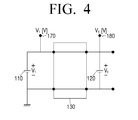
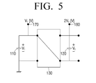
- FIGS. 3 to 5 are views illustrating examples of a power supply apparatus 100 according to an exemplary embodiment.
- the first power supply 110 and the second power supply 120 have a voltage V 1 [V] having the same level.
- the switch 130 may be connected between the first power supply 110 and the second power supply 120.
- FIG. 3 illustrates a case in which only an element connected to a first output terminal 170 is driven and an element connected to a second output terminal 180 is not driven.
- the first power supply 110 and the second power supply 120 may be short-circuited by the switch 130. Since the first power supply 110 is grounded and the second power supply 120 is not grounded, the voltage level of the first output terminal 170 formed in the first power supply 110 is V 1 [V], and the voltage level of the second output terminal 180 formed in the second power supply 120 is 0[V]. Accordingly, in order to drive only the element connected to the first output terminal 170 without driving the element connected to the second output terminal 180, the first power supply 110 and the second power supply 120 may be short-circuited by the switch 130.
- FIG. 4 illustrates a case in which the element connected to the first output terminal 170 and the element connected to the second output terminal 180 are driven by a reference voltage having a same level.
- the switch 130 is switched to connect an anode of the first power supply 110 and an anode of the second power supply 120, and is switched to connect a cathode of the first power supply 110 and a cathode of the second power supply 120, such that the first power supply 110 and the second power supply 120 are connected to each other in parallel. Since the first power supply 110 and the second power supply 120 are connected to one another in parallel by the switch 130, the voltage level of the first output terminal 170 and the voltage level of the second output terminal 180 are V 1 [V]. Accordingly, in order to drive the element connected to the first output terminal 170 and the element connected to the second output terminal 180 at a same level reference voltage, the first power supply 110 and the second power supply 120 may be connected to each other by the switch 130.
- FIG. 5 illustrates a case in which the element connected to the first output terminal 170 is driven by a predetermined reference voltage and the element connected to the second output terminal 180 is driven by a voltage exceeding the predetermined reference voltage.
- the switch 130 is switched to connect the anode of the first power supply 110 and the cathode of the second power supply 120, such that the first power supply 110 and the second power supply 120 are connected to each other in series. Since the first power supply 110 and the second power supply 120 are connected to each other in series by the switch 130, the voltage level of the first output terminal 170 is V 1 [V] and the voltage level of the second output terminal 180 is 2V 1 [V].
- the first power supply 110 and the second power supply 120 may be connected to each other in series by the switch 130.
- FIG. 6 is a view illustrating an example of a power supply apparatus according to another exemplary embodiment. Hereinafter, redundant explanations will be omitted.
- the power supply apparatus includes a plurality of power supplies and a plurality of switches.
- power supplies 110-1, 110-2, ⁇ , 110-n, and switches 130-1, 130-2, -, 130-(n-1) are shown. That is, the power supply apparatus according to another exemplary embodiment may be formed of a single array by connecting the plurality of power supplies 110-1, 110-2, ⁇ , 110-n and the plurality of switches 130-1, 130-2, ⁇ , 130-(n-1).
- the plurality of power supplies 110-1, 110-2, ⁇ , 110-n may output the same voltage level V 1 [V].
- each of the plurality of power supplies 110-1, 110-2, -, 110-n may include a single output terminal and at least one element may be connected to each of a plurality of output terminals 170-1, 170-2, ⁇ , 170-n.
- the plurality of switches 130-1, 130-2, ⁇ , 130-(n-1) may be switched so as to connect the plurality of power supplies 110-1, 110-2, ⁇ , 110-n in parallel. Accordingly, the plurality of power supplies 110-1, 110-2, ⁇ , 110-n may supply the same voltage level V 1 [V] to the elements connected thereto.
- the plurality of switches 130-1, 130-2, -, 130-(n-1) may be switched to connect the plurality of power supplies 110-1, 110-2, -, 110-n in series. Accordingly, as shown in FIG. 6 , the voltage of the first output terminal 170-1 may be V 1 [V], the voltage of the second output terminal 170-2 may be 2V 1 [V], and the voltage of the nth output terminal 170-n may be n*V 1 [V].
- the driving voltage required by each element may not be an integer multiple of the predetermined reference voltage.
- the plurality of power supplies 110-1, 110-2, ⁇ , 110-n may not output the same voltage level. That is, the first power supply, the second power supply, and the nth power supply may supply voltages of V 1 [V], V 2 [V], V n [V]
- the plurality of switches 130-1, 130-2, ⁇ , 130-(n-1) do not switch to connect the plurality of power supplies 110-1, 110-2, ⁇ , 110-n in parallel. That is, when the first event occurs, each of the plurality of power supplies may be grounded and the switches may be switched to short-circuit the plurality of power supplies 110-1, 110-2, -, 110-n. Accordingly, the voltage of the first output terminal 170-1 may be V 1 [V], the voltage of the second output terminal 170-2 may be V 2 [V], and the voltage of the nth output terminal 170-n may be V n [V].
- the plurality of switches 130-1, 130-2, -, 130-(n-1) are switched to connect the plurality of power supplies 110-1, 110-2, ⁇ , 110-n in series.
- the voltage of the first output terminal 170-1 may be V 1 [V]
- the voltage of the second output terminal 170-2 may be (V 1 +V 2 )[V]
- the voltage of the nth output terminal 170-n may be (V 1 +V 2 + ⁇ +V N )[V].
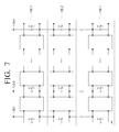
- FIG. 7 illustrates a power supply apparatus formed with a plurality of arrays which is an example of a power supply apparatus according to still another exemplary embodiment.
- the power supply apparatus according to still another exemplary embodiment includes a plurality of power supply arrays 100-1, 100-2, ⁇ , 100-n.
- the plurality of power supply arrays 100-1, 100-2, ⁇ , 100-n are electrically connected to one another, an output terminal of one of the plurality of power supply arrays 100-1, 100-2, ⁇ , 100-n may be connected to an input terminal of adjacent power supply array.
- each of the plurality of power supply arrays 100-1, 100-2, ⁇ , 100-n when each of the plurality of power supply arrays 100-1, 100-2, ⁇ , 100-n is electrically short-circuited, each of the plurality of power supply arrays 100-1, 100-2, ⁇ , 100-n may form a plurality of output terminals. In this case, elements, such as an amplifier, may be connected to the plurality of output terminals.
- a single power supply array is the same as that described in FIG. 6 and thus a redundant explanation is omitted.
- the plurality of power supply arrays 100-1, 100-2, ⁇ , 100-n may be electrically connected to one another. However, when the plurality of switches are switched to connect all of the power supplies in series, the plurality of power supply arrays 100-1, 100-2, ⁇ , 100-n may be electrically short-circuited.
- the plurality of power supply arrays 100-1, 100-2, -, 100-n may be electrically short-circuited.
- FIG. 8 is a view illustrating an example of an electronic apparatus 200 according to an exemplary embodiment.
- an electronic apparatus 200 includes a first element 250, a second element 260, and a power supply apparatus 100.
- the power supply apparatus 100 includes a plurality of power supplies, such as a first power supply 210 and a second power supply 220, a switch 230, and a controller 240.
- the power supply apparatus has been described above and thus a redundant explanation is omitted.
- the power supply apparatus 100 supplies power to the first element 250 and the second element 260.
- a plurality of power supply apparatuses may be provided.
- a plurality of power supply apparatuses may be formed and may be arranged as a single array.
- the first element 250 may be an element that is operated by a voltage less than a predetermined reference voltage in a first mode and a second mode.
- the second element 260 may be an element that is operated by a voltage less than the predetermined reference voltage in the first mode, and is operated by a voltage exceeding the predetermined reference voltage in the second mode.
- the first mode may refer to a state in which low output is required for the second element 260 and the second mode may refer to a state in which high output is required for the second element 260. Accordingly, when a low output or a high output is required for the second element 260, the first element 250 may be operated by a voltage less than the predetermined reference voltage.
- the second element 260 when a low output is required for the second element 260, the second element 260 may be operated by a voltage less than the predetermined reference voltage, and, when a high output is required for the second element 260, the second element 260 may be operated by a voltage exceeding the predetermined reference voltage.
- the electronic apparatus 200 may be an audio playback apparatus.
- the first element 250 may be a pre-amplifier and the second element 260 may be an amplifier.
- the amplifier amplifies a signal that is output from the pre-amplifier and the pre-amplifier adjusts an input signal minutely and outputs the signal to the amplifier. Accordingly, the amplifier may be operated by only low output and also may be operated by high output. Commonly, the pre-amplifier does not require a high output.
- the pre-amplifier and the amplifier are well known in the related art thus an explanation thereof is omitted.
- the first element 250 may receive power from a first power supply 210, and the second element 260 may receive power from a second power supply 220.
- the voltage level of the first power supply 210 and the second power supply 220 may be the same. Since the first element 250 does not require a high output, it may receive power from the first power supply 210 and may be driven. That is, in the first mode or second mode, the first element 250 may receive power from the first power supply 210.
- the second element 260 may require a low output or a high output when being driven. That is, in the first mode, the second element 260 may receive power from the second power supply 220.
- the switch 230 is switched to connect the first power supply 210 and the second power supply in series such that the second element 260 may receive power which is a sum of power from the first power supply 210 and power from the second power supply 220.
- the switch 230 may be switched to connect the first power supply 210 and the second power supply 220 in parallel.
- the first element 250 and the second element 260 may receive power of the same voltage level.
- the voltage level of the first and second power supplies 210 and 220 may be appropriate for driving the second element 260, but may be excessive for driving the first element 250.
- a first direct current to direct current (DC-to-DC) converter (not shown) may be connected between the first power supply 210 and the first element 250. Accordingly, the first DC-to-DC converter (not shown) may reduce the voltage level of the power supplied by the first power supply 210 and then may supply the power to the first element 250.
- the voltage level of the first power supply 210 and the second power supply 220 may be appropriate for driving the first element 250, but may be insufficient for driving the second element 260.
- a second DC-to-DC converter (not shown) may be connected between the second power supply 220 and the second element 260. Accordingly, the second DC-to-DC converter (not shown) may raise the voltage level of the power supplied by the second power supply 220 and then may supply the power to the second element 260.
- the power supply apparatus may include a plurality of power supply arrays including a plurality of power supplies and a plurality of switches 230, and an output terminal of one of the plurality of power supply arrays may be connected to an input terminal of an adjacent power supply array. An explanation of this is the same as described above and is therefore omitted.
Landscapes
- Engineering & Computer Science (AREA)
- Power Engineering (AREA)
- Direct Current Feeding And Distribution (AREA)
Abstract
Description
- This application claims priority from Korean Patent Application No.
10-2013-0063747, filed on June 3, 2013 - Apparatuses and methods consistent with exemplary embodiments relate to a power supply apparatus and an electronic apparatus having the same. More particularly, apparatuses consistent with the exemplary embodiments relate to a power supply apparatus which supplies various power levels from a plurality of power supply sources by means of a switch, and an electronic apparatus having the same.
- A battery management system (BMS) refers to a system that prevents overcharging or over discharging of a battery by monitoring the battery. A battery is, for example, a power supply source in an electronic apparatus. A BMS also increases energy efficiency and battery life by balancing voltages between battery cells.
-
FIG. 1 is a block diagram of a power supply apparatus in a related-art battery management system. Referring toFIG. 1 , the related-artpower supply apparatus 1 includes apower supply 10, afirst converter 20, and asecond converter 30. A power supply can be, for example, a device which provides electric power. Thefirst converter 20 and thesecond converter 30 may be connected to afirst element 50 and asecond element 60, respectively. The first and second element could be, for example, a pre-amplifier and an amplifier, respectively. Thepower supply 10 may be implemented by using a single battery or a plurality of batteries. When thepower supply 10 is implemented by using a plurality of batteries, the batteries are connected to one another in series or in parallel so that power is supplied to both thefirst converter 20 and thesecond converter 30. Thefirst converter 20 and thesecond converter 30 each may raise or reduce power which is supplied to drive the first element 40 and thesecond element 60 appropriately. That is, since the power supplied by thepower supply 10 has a fixed value, thefirst converter 20 and the second converter should adjust the fixed level of power supplied from thepower supply 10, in order to drive thefirst element 50 and thesecond element 60 which are operated by different optimal levels of power. - However, when the converter changes the power level, energy is lost based on the change in power level which can result in reduced efficiency. Also, since a separate converter is required, the cost increases. There is also a limit in its ability to supply an optimal level of power to each element.
- One or more exemplary embodiments may overcome the above disadvantages and other disadvantages not described above. However, it is understood that one or more exemplary embodiments are not required to overcome the disadvantages described above, and may not overcome any of the problems described above.
- One or more exemplary embodiments provide a power supply apparatus which supplies power of varying levels by connecting a plurality of power supplies in series or in parallel by using a switch, and an electronic apparatus having the same.
- According to an aspect of an exemplary embodiment, there is provided a power supply apparatus including: a plurality of power supplies arranged as a single array; a switch disposed between the plurality of power supplies configured to control connection states of the plurality of power supplies; and a controller configured to control the switch to connect the plurality of power supplies in parallel when a first event requiring a voltage less than a predetermined reference voltage occurs, and configured to control the switch to connect the plurality of power supplies in series when a second event requiring a voltage exceeding the predetermined reference voltage occurs.
- In an aspect of an exemplary embodiment, voltages of the plurality of power supplies may be the same.
- The controller may control the switch to connect an anode of a first power supply of the plurality of power supplies and an anode of a second power supply of the plurality of power supplies, and controls the switch to connect a cathode of the first power supply and a cathode of the second power supply, such that the plurality of power supplies are connected to each other in parallel.
- The controller may control the switch to connect an anode of a first power supply of the plurality of power supplies and a cathode of a second power supply of the plurality of power supplies such that the plurality of power supplies are connected to each other in series.
- The power supply apparatus may include a plurality of power supply arrays, and an output terminal of a first power supply array of the plurality of power supply arrays may be connected to an input terminal of a second power supply array which is adjacent to the first power supply array.
- According to an aspect of another exemplary embodiment, there is provided an electronic apparatus which is operable in a first mode and a second mode, the electronic apparatus including: a first element configured to be operated by a voltage less than a predetermined reference voltage in the first mode and the second mode; a second element configured to be operated by a voltage less than the predetermined reference voltage in the first mode, and configured to be operated by a voltage exceeding the predetermined reference voltage in the second mode; and a power supply apparatus configured to supply power to the first element and the second element, wherein the power supply apparatus includes: a plurality of power supplies arranged as a single array; a switch disposed between the plurality of power supplies and configured to control connection states of the plurality of power supplies; and a controller configured to control the switch to connect the plurality of power supplies in parallel when the electronic apparatus is operated in the first mode, and configured to connect the plurality of power supplies in series when the electronic apparatus is operated in the second mode.
- In an aspect of an exemplary embodiment, voltages of the plurality of power supplies may be the same.
- The electronic apparatus may further include a direct current to direct current (DC-to-DC) converter connected between the first element and one of the plurality of power supplies, and the DC-to-DC converter may reduce a voltage supplied to the first element when the electronic apparatus is operated in the second mode and thus the plurality of power supplies may be connected to one another in series.
- The power supply apparatus may include a plurality of power supply arrays including the plurality of power supplies and the switch, and an output terminal of a first power supply of the plurality of power supply arrays may be connected to an input terminal of a second power supply array of the plurality of power supply arrays which is adjacent to the first power supply array.
- The electronic apparatus may be implemented by using an audio apparatus, and the first element may be implemented by using a pre-amplifier and the second element may be implemented by using an amplifier. The first mode may be a mode in which an audio signal is output which is less than a predetermined level, and the second mode may be a mode in which an audio signal is output which exceeds the predetermined level.
- According to the various exemplary embodiments described above, the power supply apparatus supplies power of varying levels from the plurality of power supplies.
- For a better understanding of the invention, and to show how embodiments of the same may be carried into effect, reference will now be made, by way of example, to the accompanying diagrammatic drawings in which:
-
FIG. 1 is a block diagram illustrating a power supply apparatus in a related art battery management system; -
FIG. 2 is a block diagram of a power supply apparatus according to an exemplary embodiment; -
FIGS. 3 to 5 are views illustrating examples of a power supply apparatus according to an exemplary embodiment; -
FIG. 6 is a view illustrating an example of a power supply apparatus according to another exemplary embodiment; -
FIG. 7 is a view illustrating an example of a power supply apparatus according to still another exemplary embodiment; and -
FIG. 8 is a view illustrating an example of an electronic apparatus according to an exemplary embodiment. - Hereinafter, exemplary embodiments will be described in greater detail with reference to the accompanying drawings.
- In the following description, same reference numerals are used for the same elements when they are depicted in different drawings. The matters defined in the description, such as detailed construction and elements, are provided to assist in a comprehensive understanding of exemplary embodiments. Thus, it is apparent that exemplary embodiments can be carried out without those specifically defined matters. Also, functions or elements known in the related art are not described in detail since they would obscure the exemplary embodiments with unnecessary detail.
-
FIG. 2 is a block diagram illustrating apower supply apparatus 100 according to an exemplary embodiment. - Referring to
FIG. 2 , apower supply apparatus 100 according to an exemplary embodiment includes afirst power supply 110 and asecond power supply 120, aswitch 130, and acontroller 140. In the exemplary embodiment, two power supplies are illustrated, however, the exemplary embodiment is not limited to two power supplies. - The power supplies supply power to elements connected thereto. In this case, the supplied power may be direct current power or alternating current power. The power supplied to the elements may be supplied from the plurality of power supplies and each power supply may have an output terminal formed therein. The elements may include, for example, a pre-amplifier and an amplifier.
- The first output may be supplied to an element that is connected to the
first power supply 110 through the output terminal formed in thefirst power supply 110, and the second output may be supplied to an element that is connected to thesecond power supply 120 through the output terminal formed in thesecond power supply 120. Although only thefirst power supply 110 and thesecond power supply 120 are illustrated, this is merely an example and the exemplary embodiment is not limited to the two power supplies. Accordingly, the power supply of thepower supply apparatus 100 according to another exemplary embodiment may include a plurality of power supplies other than two. In this case, the plurality of power supplies may be arranged as a single array. - The
switch 130 is disposed between the plurality of power supplies to control connection states of the plurality of power supplies. As shown inFIG. 2 , theswitch 130 may be connected between thefirst power supply 110 and thesecond power supply 120. A level of power supplied by thefirst power supply 110 or thesecond power supply 120 may be changed by switching theswitch 130. - The
controller 140 may be connected to theswitch 130 and may receive an external signal. In this case, the external signal may be a signal that contains information on an optimal level of power that is required by an element which is connected to the power supply. Accordingly, a signal that contains information on an optimal level of power that is supplied by each of the plurality of power supplies may be input to thecontroller 140, and thecontroller 140 may control switching of theswitch 130 according to the input signal such that the optimal level of power is supplied to each element. - In this case, the
controller 140 may control switching of theswitch 130 to connect the plurality of power supplies in series or in parallel. That is, when a first event that requires a voltage less than a predetermined reference voltage occurs, thecontroller 140 may control theswitch 130 to connect the plurality of power supplies in parallel, and when a second event that requires a voltage exceeding the predetermined reference voltage occurs, thecontroller 140 may control theswitch 130 to connect the plurality of power supplies in series. The voltages of the plurality of power supplies may be the same. The predetermined reference voltage can be determined based on the device using the power supply. Accordingly, when the first event that requires the voltage less than the predetermined reference voltage occurs, thecontroller 140 controls theswitch 130 to connect an anode of one of the plurality of power supplies and an anode of another power supply, and controls theswitch 130 to connect a cathode of one of the plurality of power supplies and a cathode of another power supply, such that the plurality of power supplies are connected to one another in parallel. - Also, when the second event that requires a voltage exceeding the predetermined reference voltage occurs, the
controller 140 controls theswitch 130 to connect an anode of one of the plurality of power supplies and a cathode of another power supply, such that the plurality of power supplies are connected to one another in series. - The plurality of power supplies may supply the same level of voltage and the voltage level may be pre-set. That is, the
first power supply 110 and thesecond power supply 120 may supply a predetermined reference voltage to elements connected thereto, and each element may be driven by the predetermined reference voltage. Therefore, the first event refers to a case in which the elements connected to thefirst power supply 110 and thesecond power supply 120 may be driven by the predetermined reference voltage or a voltage less than the predetermined reference voltage. Therefore, when the first event occurs, the element connected to thefirst power supply 110 and the element connected to thesecond power supply 120 may be driven by the first output and the second output having the same voltage level. In this case, thefirst power supply 110 and thesecond power supply 120 may be connected to each other in parallel. - However, the element connected to the
second power supply 120 may require a high output based on a given situation. In this case, it is necessary to raise the second output and supply it to the element. That is, the element connected to thefirst power supply 110 may be driven by the predetermined reference voltage, but the element connected to thesecond power supply 120 requires a voltage which is higher than the predetermined reference voltage. Accordingly, the second event may refer to a case in which one or more of the plurality of power supplies requires a voltage exceeding the predetermined reference voltage. Therefore, when the second event occurs, the element connected to thefirst power supply 110 may be driven by the predetermined reference voltage, and the element connected to thesecond power supply 120 may be driven by a voltage level that is a sum of the voltage level of thefirst power supply 110 and the voltage level of thesecond power supply 120. In this case, theswitch 130 may be switched to connect thefirst power supply 110 and thesecond power supply 120 in series. -
FIGS. 3 to 5 are views illustrating examples of apower supply apparatus 100 according to an exemplary embodiment. - Referring to
FIGS. 3 to 5 , thefirst power supply 110 and thesecond power supply 120 have a voltage V1[V] having the same level. Theswitch 130 may be connected between thefirst power supply 110 and thesecond power supply 120. -
FIG. 3 illustrates a case in which only an element connected to afirst output terminal 170 is driven and an element connected to asecond output terminal 180 is not driven. As shown inFIG. 3 , thefirst power supply 110 and thesecond power supply 120 may be short-circuited by theswitch 130. Since thefirst power supply 110 is grounded and thesecond power supply 120 is not grounded, the voltage level of thefirst output terminal 170 formed in thefirst power supply 110 is V1[V], and the voltage level of thesecond output terminal 180 formed in thesecond power supply 120 is 0[V]. Accordingly, in order to drive only the element connected to thefirst output terminal 170 without driving the element connected to thesecond output terminal 180, thefirst power supply 110 and thesecond power supply 120 may be short-circuited by theswitch 130. -
FIG. 4 illustrates a case in which the element connected to thefirst output terminal 170 and the element connected to thesecond output terminal 180 are driven by a reference voltage having a same level. As shown inFIG. 4 , theswitch 130 is switched to connect an anode of thefirst power supply 110 and an anode of thesecond power supply 120, and is switched to connect a cathode of thefirst power supply 110 and a cathode of thesecond power supply 120, such that thefirst power supply 110 and thesecond power supply 120 are connected to each other in parallel. Since thefirst power supply 110 and thesecond power supply 120 are connected to one another in parallel by theswitch 130, the voltage level of thefirst output terminal 170 and the voltage level of thesecond output terminal 180 are V1[V]. Accordingly, in order to drive the element connected to thefirst output terminal 170 and the element connected to thesecond output terminal 180 at a same level reference voltage, thefirst power supply 110 and thesecond power supply 120 may be connected to each other by theswitch 130. -
FIG. 5 illustrates a case in which the element connected to thefirst output terminal 170 is driven by a predetermined reference voltage and the element connected to thesecond output terminal 180 is driven by a voltage exceeding the predetermined reference voltage. As shown inFIG. 5 , theswitch 130 is switched to connect the anode of thefirst power supply 110 and the cathode of thesecond power supply 120, such that thefirst power supply 110 and thesecond power supply 120 are connected to each other in series. Since thefirst power supply 110 and thesecond power supply 120 are connected to each other in series by theswitch 130, the voltage level of thefirst output terminal 170 is V1[V] and the voltage level of thesecond output terminal 180 is 2V1[V]. Accordingly, in order to drive the element connected to thefirst output terminal 170 by the predetermined reference voltage and in order to drive the element connected to thesecond output terminal 180 by a voltage exceeding the predetermined reference voltage, thefirst power supply 110 and thesecond power supply 120 may be connected to each other in series by theswitch 130. -
FIG. 6 is a view illustrating an example of a power supply apparatus according to another exemplary embodiment. Hereinafter, redundant explanations will be omitted. - Referring to
FIG. 6 , the power supply apparatus according to another exemplary embodiment includes a plurality of power supplies and a plurality of switches. InFIG. 6 , power supplies 110-1, 110-2, ∼, 110-n, and switches 130-1, 130-2, -, 130-(n-1) are shown. That is, the power supply apparatus according to another exemplary embodiment may be formed of a single array by connecting the plurality of power supplies 110-1, 110-2, ∼, 110-n and the plurality of switches 130-1, 130-2, ∼, 130-(n-1). The plurality of power supplies 110-1, 110-2, ∼, 110-n may output the same voltage level V1[V]. Since a switch is disposed between two power supplies, (n) number of power supplies and (n-1) number of switches are illustrated inFIG. 6 . Also, each of the plurality of power supplies 110-1, 110-2, -, 110-n may include a single output terminal and at least one element may be connected to each of a plurality of output terminals 170-1, 170-2, ∼, 170-n. - When the first event occurs, the plurality of switches 130-1, 130-2, ∼, 130-(n-1) may be switched so as to connect the plurality of power supplies 110-1, 110-2, ∼, 110-n in parallel. Accordingly, the plurality of power supplies 110-1, 110-2, ∼, 110-n may supply the same voltage level V1[V] to the elements connected thereto.
- Also, when the second event occurs, the plurality of switches 130-1, 130-2, -, 130-(n-1) may be switched to connect the plurality of power supplies 110-1, 110-2, -, 110-n in series. Accordingly, as shown in
FIG. 6 , the voltage of the first output terminal 170-1 may be V1[V], the voltage of the second output terminal 170-2 may be 2V1[V], and the voltage of the nth output terminal 170-n may be n*V1[V]. - Depending on the situation, the driving voltage required by each element may not be an integer multiple of the predetermined reference voltage. In this case, the plurality of power supplies 110-1, 110-2, ∼, 110-n may not output the same voltage level. That is, the first power supply, the second power supply, and the nth power supply may supply voltages of V1[V], V2[V], Vn[V]
- In this case, even when the first event occurs, the plurality of switches 130-1, 130-2, ∼, 130-(n-1) do not switch to connect the plurality of power supplies 110-1, 110-2, ∼, 110-n in parallel. That is, when the first event occurs, each of the plurality of power supplies may be grounded and the switches may be switched to short-circuit the plurality of power supplies 110-1, 110-2, -, 110-n. Accordingly, the voltage of the first output terminal 170-1 may be V1[V], the voltage of the second output terminal 170-2 may be V2[V], and the voltage of the nth output terminal 170-n may be Vn[V].
- Also, when the second event occurs, the plurality of switches 130-1, 130-2, -, 130-(n-1) are switched to connect the plurality of power supplies 110-1, 110-2, ∼, 110-n in series. Accordingly, the voltage of the first output terminal 170-1 may be V1[V], the voltage of the second output terminal 170-2 may be (V1+V2)[V], and the voltage of the nth output terminal 170-n may be (V1+V2+∼+VN)[V].
-
FIG. 7 illustrates a power supply apparatus formed with a plurality of arrays which is an example of a power supply apparatus according to still another exemplary embodiment. Referring toFIG. 7 , the power supply apparatus according to still another exemplary embodiment includes a plurality of power supply arrays 100-1, 100-2, ∼, 100-n. When the plurality of power supply arrays 100-1, 100-2, ∼, 100-n are electrically connected to one another, an output terminal of one of the plurality of power supply arrays 100-1, 100-2, ∼, 100-n may be connected to an input terminal of adjacent power supply array. Also, when each of the plurality of power supply arrays 100-1, 100-2, ∼, 100-n is electrically short-circuited, each of the plurality of power supply arrays 100-1, 100-2, ∼, 100-n may form a plurality of output terminals. In this case, elements, such as an amplifier, may be connected to the plurality of output terminals. A single power supply array is the same as that described inFIG. 6 and thus a redundant explanation is omitted. - When the plurality of switches are switched to short-circuit all of the power supplies or are switched to connect all of the power supplies in parallel, the plurality of power supply arrays 100-1, 100-2, ∼, 100-n may be electrically connected to one another. However, when the plurality of switches are switched to connect all of the power supplies in series, the plurality of power supply arrays 100-1, 100-2, ∼, 100-n may be electrically short-circuited. Also, when the plurality of switches included in a single power supply array are switched to connect all of the power supplies in series, and the plurality of switches included in an another power supply array, which is adjacent to the single power supply array, is switched to connect all of the power supplies in parallel, the plurality of power supply arrays 100-1, 100-2, -, 100-n may be electrically short-circuited.
-
FIG. 8 is a view illustrating an example of anelectronic apparatus 200 according to an exemplary embodiment. - Referring to
FIG. 8 , anelectronic apparatus 200 according to an exemplary embodiment includes afirst element 250, asecond element 260, and apower supply apparatus 100. - The
power supply apparatus 100 includes a plurality of power supplies, such as afirst power supply 210 and asecond power supply 220, aswitch 230, and acontroller 240. The power supply apparatus has been described above and thus a redundant explanation is omitted. - The
power supply apparatus 100 supplies power to thefirst element 250 and thesecond element 260. In this case, a plurality of power supply apparatuses may be provided. Also, a plurality of power supply apparatuses may be formed and may be arranged as a single array. - The
first element 250 may be an element that is operated by a voltage less than a predetermined reference voltage in a first mode and a second mode. Also, thesecond element 260 may be an element that is operated by a voltage less than the predetermined reference voltage in the first mode, and is operated by a voltage exceeding the predetermined reference voltage in the second mode. In this case, the first mode may refer to a state in which low output is required for thesecond element 260 and the second mode may refer to a state in which high output is required for thesecond element 260. Accordingly, when a low output or a high output is required for thesecond element 260, thefirst element 250 may be operated by a voltage less than the predetermined reference voltage. Also, when a low output is required for thesecond element 260, thesecond element 260 may be operated by a voltage less than the predetermined reference voltage, and, when a high output is required for thesecond element 260, thesecond element 260 may be operated by a voltage exceeding the predetermined reference voltage. - The
electronic apparatus 200 according to an exemplary embodiment may be an audio playback apparatus. In this case, thefirst element 250 may be a pre-amplifier and thesecond element 260 may be an amplifier. The amplifier amplifies a signal that is output from the pre-amplifier and the pre-amplifier adjusts an input signal minutely and outputs the signal to the amplifier. Accordingly, the amplifier may be operated by only low output and also may be operated by high output. Commonly, the pre-amplifier does not require a high output. The pre-amplifier and the amplifier are well known in the related art thus an explanation thereof is omitted. - As shown in
FIG. 8 , thefirst element 250 may receive power from afirst power supply 210, and thesecond element 260 may receive power from asecond power supply 220. In this case, the voltage level of thefirst power supply 210 and thesecond power supply 220 may be the same. Since thefirst element 250 does not require a high output, it may receive power from thefirst power supply 210 and may be driven. That is, in the first mode or second mode, thefirst element 250 may receive power from thefirst power supply 210. Thesecond element 260 may require a low output or a high output when being driven. That is, in the first mode, thesecond element 260 may receive power from thesecond power supply 220. However, in the second mode, thesecond element 260 cannot be driven only by the power supplied from thesecond power supply 220. Accordingly, theswitch 230 is switched to connect thefirst power supply 210 and the second power supply in series such that thesecond element 260 may receive power which is a sum of power from thefirst power supply 210 and power from thesecond power supply 220. - On the other hand, the
switch 230 may be switched to connect thefirst power supply 210 and thesecond power supply 220 in parallel. When the voltage level of thefirst power supply 210 is the same as that of thesecond power supply 220, thefirst element 250 and thesecond element 260 may receive power of the same voltage level. - The voltage level of the first and
second power supplies second element 260, but may be excessive for driving thefirst element 250. In this case, a first direct current to direct current (DC-to-DC) converter (not shown) may be connected between thefirst power supply 210 and thefirst element 250. Accordingly, the first DC-to-DC converter (not shown) may reduce the voltage level of the power supplied by thefirst power supply 210 and then may supply the power to thefirst element 250. - The voltage level of the
first power supply 210 and thesecond power supply 220 may be appropriate for driving thefirst element 250, but may be insufficient for driving thesecond element 260. In this case, a second DC-to-DC converter (not shown) may be connected between thesecond power supply 220 and thesecond element 260. Accordingly, the second DC-to-DC converter (not shown) may raise the voltage level of the power supplied by thesecond power supply 220 and then may supply the power to thesecond element 260. - The power supply apparatus may include a plurality of power supply arrays including a plurality of power supplies and a plurality of
switches 230, and an output terminal of one of the plurality of power supply arrays may be connected to an input terminal of an adjacent power supply array. An explanation of this is the same as described above and is therefore omitted. - The foregoing exemplary embodiments are merely exemplary and are not to be construed as limiting the present inventive concept. The exemplary embodiments can be readily applied to other types of apparatuses. Also, the description of the exemplary embodiments is intended to be illustrative, and not to limit the scope of the claims, and many alternatives, modifications, and variations will be apparent to those skilled in the art.
- Attention is directed to all papers and documents which are filed concurrently with or previous to this specification in connection with this application and which are open to public inspection with this specification, and the contents of all such papers and documents are incorporated herein by reference.
- All of the features disclosed in this specification (including any accompanying claims, abstract and drawings), and/or all of the steps of any method or process so disclosed, may be combined in any combination, except combinations where at least some of such features and/or steps are mutually exclusive.
- Each feature disclosed in this specification (including any accompanying claims, abstract and drawings) may be replaced by alternative features serving the same, equivalent or similar purpose, unless expressly stated otherwise. Thus, unless expressly stated otherwise, each feature disclosed is one example only of a generic series of equivalent or similar features.
- The invention is not restricted to the details of the foregoing embodiment(s). The invention extends to any novel one, or any novel combination, of the features disclosed in this specification (including any accompanying claims, abstract and drawings), or to any novel one, or any novel combination, of the steps of any method or process so disclosed.
Claims (12)
- A power supply apparatus comprising:a plurality of power supplies arranged as a single array;a switch disposed between the plurality of power supplies configured to control connection states of the plurality of power supplies; anda controller configured to control the switch to connect the plurality of power supplies in parallel when a first event requiring a voltage less than a predetermined reference voltage occurs, and configured to control the switch to connect the plurality of power supplies in series when a second event requiring a voltage exceeding the predetermined reference voltage occurs.
- The power supply apparatus as claimed in claim 1, wherein voltages of the plurality of power supplies are the same.
- The power supply apparatus as claimed in claim 2, wherein the controller controls the switch to connect an anode of a first power supply of the plurality of power supplies and an anode of a second power supply of the plurality of power supplies, and controls the switch to connect a cathode of the first power supply and a cathode of the second power supply, such that the plurality of power supplies are connected to each other in parallel.
- The power supply apparatus as claimed in anyone of claim 2 to 3, wherein the controller controls the switch to connect an anode of a first power supply of the plurality of power supplies and a cathode of a second power supply of the plurality of power supplies such that the plurality of power supplies are connected to each other in series.
- The power supply apparatus as claimed in anyone of claim 2 to 4, wherein the power supply apparatus comprises a plurality of power supply arrays, and
wherein an output terminal of a first power supply array of the plurality of power supply arrays is connected to an input terminal of a second power supply array of the plurality of power supply arrays which is adjacent to the first power supply array. - An electronic apparatus which is operable in a first mode and a second mode, the electronic apparatus comprising:a first element configured to be operated by a voltage less than a predetermined reference voltage in the first mode and in the second mode;a second element configured to be operated by a voltage less than the predetermined reference voltage in the first mode, and configured to be operated by a voltage exceeding the predetermined reference voltage in the second mode; anda power supply apparatus configured to supply power to the first element and the second element,wherein the power supply apparatus comprises:a plurality of power supplies arranged as a single array;a switch disposed between the plurality of power supplies and configured to control connection states of the plurality of power supplies; anda controller configured to control the switch to connect the plurality of power supplies in parallel when the electronic apparatus is operated in the first mode, and configured to connect the plurality of power supplies in series when the electronic apparatus is operated in the second mode.
- The electronic apparatus as claimed in claim 6, wherein voltages of the plurality of power supplies are the same.
- The electronic apparatus as claimed in anyone of claim 6 to 7, further comprising a direct current to direct current (DC-to- DC) converter connected between the first element and one of the plurality of power supplies,
wherein the DC- to-DC converter is configured to reduce a voltage supplied to the first element when the electronic apparatus is operated in the second mode and the plurality of power supplies are connected to each another in a series. - The electronic apparatus as claimed in anyone of claim 6 to 8, wherein the power supply apparatus comprises a plurality of power supply arrays comprising the plurality of power supplies and the switch, and
wherein an output terminal of a first power supply array of the plurality of power supply arrays is connected to an input terminal of a second power supply array of the plurality of power supply arrays which is adjacent to the first power supply array. - The electronic apparatus as claimed in anyone of claim 6 to 9, wherein the electronic apparatus is implemented using an audio apparatus, the first element is implemented using a pre-amplifier, and the second element is implemented by using an amplifier, and
wherein the first mode is a mode in which an audio signal is output which is less than a predetermined level, and the second mode is a mode in which an audio signal is output which exceeds the predetermined level. - A power supply apparatus comprising:a first power supply and a second power supply arranged as a single array;a switch located between the first power supply and the second power supply and configured to control a connection state of the first power supply and the second power supply; anda controller configured to control the switch to connect the first power supply and the second power supply in parallel when a first event requiring a voltage less than a predetermined reference voltage occurs, and configured to control the switch to connect the first power supply and the second power supply in series when a second event requiring a voltage exceeding the predetermined reference voltage occurs.
- The power supply apparatus as claimed in claim 5, wherein a power supply array comprises the plurality of power supplies and the switch.
Applications Claiming Priority (1)
| Application Number | Priority Date | Filing Date | Title |
|---|---|---|---|
| KR1020130063747A KR20140142111A (en) | 2013-06-03 | 2013-06-03 | Power supply apparatus and electric apparatus having the same |
Publications (3)
| Publication Number | Publication Date |
|---|---|
| EP2811611A2 true EP2811611A2 (en) | 2014-12-10 |
| EP2811611A3 EP2811611A3 (en) | 2014-12-24 |
| EP2811611B1 EP2811611B1 (en) | 2016-01-06 |
Family
ID=49999769
Family Applications (1)
| Application Number | Title | Priority Date | Filing Date |
|---|---|---|---|
| EP14152403.3A Not-in-force EP2811611B1 (en) | 2013-06-03 | 2014-01-24 | Power supply apparatus and electronic apparatus having the same |
Country Status (3)
| Country | Link |
|---|---|
| US (1) | US10177567B2 (en) |
| EP (1) | EP2811611B1 (en) |
| KR (1) | KR20140142111A (en) |
Families Citing this family (2)
| Publication number | Priority date | Publication date | Assignee | Title |
|---|---|---|---|---|
| US10432130B2 (en) * | 2017-11-28 | 2019-10-01 | GM Global Technology Operations LLC | Electric powertrain and a method of operating the same |
| US10369896B2 (en) | 2017-11-28 | 2019-08-06 | GM Global Technology Operations LLC | Apparatus and method for flexible DC fast charging of an electrified vehicle |
Family Cites Families (17)
| Publication number | Priority date | Publication date | Assignee | Title |
|---|---|---|---|---|
| US4175249A (en) * | 1978-06-19 | 1979-11-20 | The United States Of America As Represented By The Administrator Of The National Aeronautics And Space Administration | Self-reconfiguring solar cell system |
| KR100228731B1 (en) * | 1997-03-19 | 1999-11-01 | 윤종용 | Power supply control circuit and method for voice processing part |
| US6268711B1 (en) * | 1999-05-05 | 2001-07-31 | Texas Instruments Incorporated | Battery manager |
| EP1087495A2 (en) * | 1999-09-13 | 2001-03-28 | Lucent Technologies Inc. | Off line battery equalizer with initial trickle charging circuit |
| AUPR269301A0 (en) * | 2001-01-24 | 2001-02-22 | Cochlear Limited | Power supply for a cochlear implant |
| US6624535B2 (en) * | 2001-02-17 | 2003-09-23 | Intel Corporation | Digitally controlling the output voltage of a plurality of voltage sources |
| CA2463135C (en) * | 2001-10-11 | 2014-10-07 | Denovo Research, Llc | Dynamic battery array controllable to provide individual electrical power busses for different electrical loads |
| US6879134B2 (en) * | 2003-02-11 | 2005-04-12 | O2Micro International Limited | Selector circuit for power management in multiple battery systems |
| FR2895585B1 (en) | 2005-12-22 | 2008-04-18 | Sagem Defense Securite | POWER MANAGEMENT METHOD AND POWER CIRCUIT COMPRISING TWO BATTERIES |
| US20090079412A1 (en) * | 2007-09-24 | 2009-03-26 | Yao Hsien Kuo | Apparatus and method for controlling the output of a photovoltaic array |
| JP5525743B2 (en) * | 2009-03-30 | 2014-06-18 | 株式会社日本総合研究所 | Battery control device, battery control method, and vehicle |
| US20100289447A1 (en) * | 2009-05-18 | 2010-11-18 | Dobson Eric L | System and method for power management of energy storage devices |
| CN101964523A (en) * | 2009-07-21 | 2011-02-02 | 鸿富锦精密工业(深圳)有限公司 | Power supply method |
| CN101800498B (en) * | 2010-04-01 | 2013-12-04 | 华为技术有限公司 | Solar energy power generation system, control device and control method |
| JP2013017262A (en) * | 2011-06-30 | 2013-01-24 | Sanyo Electric Co Ltd | Inverter and power conversion device mounted with the same |
| US8970065B2 (en) * | 2011-08-04 | 2015-03-03 | Eaton Corporation | System and method for increasing voltage in a photovoltaic inverter |
| US9269834B2 (en) * | 2012-06-29 | 2016-02-23 | Nxp B.V. | Photovoltaic module monitoring and control |
-
2013
- 2013-06-03 KR KR1020130063747A patent/KR20140142111A/en not_active Ceased
-
2014
- 2014-01-24 EP EP14152403.3A patent/EP2811611B1/en not_active Not-in-force
- 2014-04-01 US US14/242,134 patent/US10177567B2/en not_active Expired - Fee Related
Non-Patent Citations (1)
| Title |
|---|
| None |
Also Published As
| Publication number | Publication date |
|---|---|
| US10177567B2 (en) | 2019-01-08 |
| KR20140142111A (en) | 2014-12-11 |
| US20140354060A1 (en) | 2014-12-04 |
| EP2811611B1 (en) | 2016-01-06 |
| EP2811611A3 (en) | 2014-12-24 |
Similar Documents
| Publication | Publication Date | Title |
|---|---|---|
| CA2758261C (en) | Battery systems and operational methods | |
| EP2201659B1 (en) | Two-stage charge equalization method and apparatus for series-connected battery string | |
| US8716894B2 (en) | Series-parallel reconfigurable cell voltage equalization circuit designed using MOSFET as switches thereof, and driver circuit thereof | |
| US8872476B2 (en) | Charging management system and charger with the same | |
| US20170217318A1 (en) | Battery pack configuration | |
| US20140210419A1 (en) | Battery pack and method for minimizing cell voltage deviations | |
| US10374442B2 (en) | Integrated multiple voltage energy storage system and method | |
| KR20160043838A (en) | Apparatus and method for managing battery | |
| US20130026992A1 (en) | Rechargeable battery device, and power supplying system incorporating the same | |
| JP2011223854A5 (en) | ||
| JP6969981B2 (en) | Spacecraft power system by solar power generation | |
| WO2016063760A1 (en) | Power supply device, protective device, and protection method | |
| JP5569418B2 (en) | Battery monitoring device | |
| CN103972956A (en) | Battery and method for regulating a battery voltage using switch-on probabilities | |
| US20160036251A1 (en) | Quick low-voltage rechargeable battery | |
| US20190027972A1 (en) | Wireless power system | |
| JP6066840B2 (en) | Charge / discharge control circuit and battery device | |
| KR20120112072A (en) | Auxiliary battery charging apparatus | |
| EP2811611A2 (en) | Power supply apparatus and electronic apparatus having the same | |
| EP2846387B1 (en) | Apparatus and method for controlling fuel cell system using sub-power conditioning system | |
| KR102131948B1 (en) | Variable capacity power bank system | |
| US20160332528A1 (en) | Electrochemical composite storage system | |
| WO2012111410A1 (en) | Electric cell system | |
| EP3425758A1 (en) | Power apparatus operating method, power apparatus, and power apparatus management system | |
| KR20250015180A (en) | Charging and discharging control apparatus, dual battery pack system, electric vehicle and charging and discharging control method |
Legal Events
| Date | Code | Title | Description |
|---|---|---|---|
| PUAL | Search report despatched |
Free format text: ORIGINAL CODE: 0009013 |
|
| PUAI | Public reference made under article 153(3) epc to a published international application that has entered the european phase |
Free format text: ORIGINAL CODE: 0009012 |
|
| 17P | Request for examination filed |
Effective date: 20140124 |
|
| AK | Designated contracting states |
Kind code of ref document: A2 Designated state(s): AL AT BE BG CH CY CZ DE DK EE ES FI FR GB GR HR HU IE IS IT LI LT LU LV MC MK MT NL NO PL PT RO RS SE SI SK SM TR |
|
| AX | Request for extension of the european patent |
Extension state: BA ME |
|
| AK | Designated contracting states |
Kind code of ref document: A3 Designated state(s): AL AT BE BG CH CY CZ DE DK EE ES FI FR GB GR HR HU IE IS IT LI LT LU LV MC MK MT NL NO PL PT RO RS SE SI SK SM TR |
|
| AX | Request for extension of the european patent |
Extension state: BA ME |
|
| RIC1 | Information provided on ipc code assigned before grant |
Ipc: H02J 7/34 20060101ALI20141117BHEP Ipc: H02J 7/00 20060101AFI20141117BHEP |
|
| R17P | Request for examination filed (corrected) |
Effective date: 20150624 |
|
| RBV | Designated contracting states (corrected) |
Designated state(s): AL AT BE BG CH CY CZ DE DK EE ES FI FR GB GR HR HU IE IS IT LI LT LU LV MC MK MT NL NO PL PT RO RS SE SI SK SM TR |
|
| GRAP | Despatch of communication of intention to grant a patent |
Free format text: ORIGINAL CODE: EPIDOSNIGR1 |
|
| INTG | Intention to grant announced |
Effective date: 20150910 |
|
| INTG | Intention to grant announced |
Effective date: 20150917 |
|
| GRAS | Grant fee paid |
Free format text: ORIGINAL CODE: EPIDOSNIGR3 |
|
| GRAA | (expected) grant |
Free format text: ORIGINAL CODE: 0009210 |
|
| AK | Designated contracting states |
Kind code of ref document: B1 Designated state(s): AL AT BE BG CH CY CZ DE DK EE ES FI FR GB GR HR HU IE IS IT LI LT LU LV MC MK MT NL NO PL PT RO RS SE SI SK SM TR |
|
| REG | Reference to a national code |
Ref country code: GB Ref legal event code: FG4D |
|
| REG | Reference to a national code |
Ref country code: CH Ref legal event code: EP |
|
| REG | Reference to a national code |
Ref country code: IE Ref legal event code: FG4D |
|
| REG | Reference to a national code |
Ref country code: AT Ref legal event code: REF Ref document number: 769602 Country of ref document: AT Kind code of ref document: T Effective date: 20160215 |
|
| REG | Reference to a national code |
Ref country code: DE Ref legal event code: R096 Ref document number: 602014000663 Country of ref document: DE |
|
| REG | Reference to a national code |
Ref country code: NL Ref legal event code: FP |
|
| REG | Reference to a national code |
Ref country code: LT Ref legal event code: MG4D |
|
| REG | Reference to a national code |
Ref country code: AT Ref legal event code: MK05 Ref document number: 769602 Country of ref document: AT Kind code of ref document: T Effective date: 20160106 |
|
| PG25 | Lapsed in a contracting state [announced via postgrant information from national office to epo] |
Ref country code: BE Free format text: LAPSE BECAUSE OF NON-PAYMENT OF DUE FEES Effective date: 20160131 |
|
| PG25 | Lapsed in a contracting state [announced via postgrant information from national office to epo] |
Ref country code: GR Free format text: LAPSE BECAUSE OF FAILURE TO SUBMIT A TRANSLATION OF THE DESCRIPTION OR TO PAY THE FEE WITHIN THE PRESCRIBED TIME-LIMIT Effective date: 20160407 Ref country code: NO Free format text: LAPSE BECAUSE OF FAILURE TO SUBMIT A TRANSLATION OF THE DESCRIPTION OR TO PAY THE FEE WITHIN THE PRESCRIBED TIME-LIMIT Effective date: 20160406 Ref country code: FI Free format text: LAPSE BECAUSE OF FAILURE TO SUBMIT A TRANSLATION OF THE DESCRIPTION OR TO PAY THE FEE WITHIN THE PRESCRIBED TIME-LIMIT Effective date: 20160106 Ref country code: ES Free format text: LAPSE BECAUSE OF FAILURE TO SUBMIT A TRANSLATION OF THE DESCRIPTION OR TO PAY THE FEE WITHIN THE PRESCRIBED TIME-LIMIT Effective date: 20160106 Ref country code: HR Free format text: LAPSE BECAUSE OF FAILURE TO SUBMIT A TRANSLATION OF THE DESCRIPTION OR TO PAY THE FEE WITHIN THE PRESCRIBED TIME-LIMIT Effective date: 20160106 Ref country code: IT Free format text: LAPSE BECAUSE OF FAILURE TO SUBMIT A TRANSLATION OF THE DESCRIPTION OR TO PAY THE FEE WITHIN THE PRESCRIBED TIME-LIMIT Effective date: 20160106 |
|
| PG25 | Lapsed in a contracting state [announced via postgrant information from national office to epo] |
Ref country code: PL Free format text: LAPSE BECAUSE OF FAILURE TO SUBMIT A TRANSLATION OF THE DESCRIPTION OR TO PAY THE FEE WITHIN THE PRESCRIBED TIME-LIMIT Effective date: 20160106 Ref country code: LT Free format text: LAPSE BECAUSE OF FAILURE TO SUBMIT A TRANSLATION OF THE DESCRIPTION OR TO PAY THE FEE WITHIN THE PRESCRIBED TIME-LIMIT Effective date: 20160106 Ref country code: IS Free format text: LAPSE BECAUSE OF FAILURE TO SUBMIT A TRANSLATION OF THE DESCRIPTION OR TO PAY THE FEE WITHIN THE PRESCRIBED TIME-LIMIT Effective date: 20160506 Ref country code: PT Free format text: LAPSE BECAUSE OF FAILURE TO SUBMIT A TRANSLATION OF THE DESCRIPTION OR TO PAY THE FEE WITHIN THE PRESCRIBED TIME-LIMIT Effective date: 20160506 Ref country code: RS Free format text: LAPSE BECAUSE OF FAILURE TO SUBMIT A TRANSLATION OF THE DESCRIPTION OR TO PAY THE FEE WITHIN THE PRESCRIBED TIME-LIMIT Effective date: 20160106 Ref country code: SE Free format text: LAPSE BECAUSE OF FAILURE TO SUBMIT A TRANSLATION OF THE DESCRIPTION OR TO PAY THE FEE WITHIN THE PRESCRIBED TIME-LIMIT Effective date: 20160106 Ref country code: LV Free format text: LAPSE BECAUSE OF FAILURE TO SUBMIT A TRANSLATION OF THE DESCRIPTION OR TO PAY THE FEE WITHIN THE PRESCRIBED TIME-LIMIT Effective date: 20160106 Ref country code: AT Free format text: LAPSE BECAUSE OF FAILURE TO SUBMIT A TRANSLATION OF THE DESCRIPTION OR TO PAY THE FEE WITHIN THE PRESCRIBED TIME-LIMIT Effective date: 20160106 |
|
| REG | Reference to a national code |
Ref country code: DE Ref legal event code: R097 Ref document number: 602014000663 Country of ref document: DE |
|
| PG25 | Lapsed in a contracting state [announced via postgrant information from national office to epo] |
Ref country code: EE Free format text: LAPSE BECAUSE OF FAILURE TO SUBMIT A TRANSLATION OF THE DESCRIPTION OR TO PAY THE FEE WITHIN THE PRESCRIBED TIME-LIMIT Effective date: 20160106 Ref country code: MC Free format text: LAPSE BECAUSE OF FAILURE TO SUBMIT A TRANSLATION OF THE DESCRIPTION OR TO PAY THE FEE WITHIN THE PRESCRIBED TIME-LIMIT Effective date: 20160106 Ref country code: DK Free format text: LAPSE BECAUSE OF FAILURE TO SUBMIT A TRANSLATION OF THE DESCRIPTION OR TO PAY THE FEE WITHIN THE PRESCRIBED TIME-LIMIT Effective date: 20160106 |
|
| REG | Reference to a national code |
Ref country code: IE Ref legal event code: MM4A |
|
| PLBE | No opposition filed within time limit |
Free format text: ORIGINAL CODE: 0009261 |
|
| STAA | Information on the status of an ep patent application or granted ep patent |
Free format text: STATUS: NO OPPOSITION FILED WITHIN TIME LIMIT |
|
| PG25 | Lapsed in a contracting state [announced via postgrant information from national office to epo] |
Ref country code: SK Free format text: LAPSE BECAUSE OF FAILURE TO SUBMIT A TRANSLATION OF THE DESCRIPTION OR TO PAY THE FEE WITHIN THE PRESCRIBED TIME-LIMIT Effective date: 20160106 Ref country code: SM Free format text: LAPSE BECAUSE OF FAILURE TO SUBMIT A TRANSLATION OF THE DESCRIPTION OR TO PAY THE FEE WITHIN THE PRESCRIBED TIME-LIMIT Effective date: 20160106 Ref country code: CZ Free format text: LAPSE BECAUSE OF FAILURE TO SUBMIT A TRANSLATION OF THE DESCRIPTION OR TO PAY THE FEE WITHIN THE PRESCRIBED TIME-LIMIT Effective date: 20160106 Ref country code: RO Free format text: LAPSE BECAUSE OF FAILURE TO SUBMIT A TRANSLATION OF THE DESCRIPTION OR TO PAY THE FEE WITHIN THE PRESCRIBED TIME-LIMIT Effective date: 20160106 |
|
| 26N | No opposition filed |
Effective date: 20161007 |
|
| PG25 | Lapsed in a contracting state [announced via postgrant information from national office to epo] |
Ref country code: BE Free format text: LAPSE BECAUSE OF FAILURE TO SUBMIT A TRANSLATION OF THE DESCRIPTION OR TO PAY THE FEE WITHIN THE PRESCRIBED TIME-LIMIT Effective date: 20160106 |
|
| REG | Reference to a national code |
Ref country code: FR Ref legal event code: ST Effective date: 20161205 |
|
| PG25 | Lapsed in a contracting state [announced via postgrant information from national office to epo] |
Ref country code: FR Free format text: LAPSE BECAUSE OF NON-PAYMENT OF DUE FEES Effective date: 20160307 Ref country code: IE Free format text: LAPSE BECAUSE OF NON-PAYMENT OF DUE FEES Effective date: 20160124 |
|
| PG25 | Lapsed in a contracting state [announced via postgrant information from national office to epo] |
Ref country code: SI Free format text: LAPSE BECAUSE OF FAILURE TO SUBMIT A TRANSLATION OF THE DESCRIPTION OR TO PAY THE FEE WITHIN THE PRESCRIBED TIME-LIMIT Effective date: 20160106 Ref country code: BG Free format text: LAPSE BECAUSE OF FAILURE TO SUBMIT A TRANSLATION OF THE DESCRIPTION OR TO PAY THE FEE WITHIN THE PRESCRIBED TIME-LIMIT Effective date: 20160406 |
|
| PG25 | Lapsed in a contracting state [announced via postgrant information from national office to epo] |
Ref country code: MT Free format text: LAPSE BECAUSE OF FAILURE TO SUBMIT A TRANSLATION OF THE DESCRIPTION OR TO PAY THE FEE WITHIN THE PRESCRIBED TIME-LIMIT Effective date: 20160106 |
|
| REG | Reference to a national code |
Ref country code: CH Ref legal event code: PL |
|
| PG25 | Lapsed in a contracting state [announced via postgrant information from national office to epo] |
Ref country code: LI Free format text: LAPSE BECAUSE OF NON-PAYMENT OF DUE FEES Effective date: 20170131 Ref country code: CH Free format text: LAPSE BECAUSE OF NON-PAYMENT OF DUE FEES Effective date: 20170131 |
|
| PG25 | Lapsed in a contracting state [announced via postgrant information from national office to epo] |
Ref country code: HU Free format text: LAPSE BECAUSE OF FAILURE TO SUBMIT A TRANSLATION OF THE DESCRIPTION OR TO PAY THE FEE WITHIN THE PRESCRIBED TIME-LIMIT; INVALID AB INITIO Effective date: 20140124 |
|
| PG25 | Lapsed in a contracting state [announced via postgrant information from national office to epo] |
Ref country code: MK Free format text: LAPSE BECAUSE OF FAILURE TO SUBMIT A TRANSLATION OF THE DESCRIPTION OR TO PAY THE FEE WITHIN THE PRESCRIBED TIME-LIMIT Effective date: 20160106 Ref country code: LU Free format text: LAPSE BECAUSE OF NON-PAYMENT OF DUE FEES Effective date: 20160124 Ref country code: CY Free format text: LAPSE BECAUSE OF FAILURE TO SUBMIT A TRANSLATION OF THE DESCRIPTION OR TO PAY THE FEE WITHIN THE PRESCRIBED TIME-LIMIT Effective date: 20160106 Ref country code: MT Free format text: LAPSE BECAUSE OF FAILURE TO SUBMIT A TRANSLATION OF THE DESCRIPTION OR TO PAY THE FEE WITHIN THE PRESCRIBED TIME-LIMIT Effective date: 20160131 |
|
| PG25 | Lapsed in a contracting state [announced via postgrant information from national office to epo] |
Ref country code: AL Free format text: LAPSE BECAUSE OF FAILURE TO SUBMIT A TRANSLATION OF THE DESCRIPTION OR TO PAY THE FEE WITHIN THE PRESCRIBED TIME-LIMIT Effective date: 20160106 Ref country code: TR Free format text: LAPSE BECAUSE OF FAILURE TO SUBMIT A TRANSLATION OF THE DESCRIPTION OR TO PAY THE FEE WITHIN THE PRESCRIBED TIME-LIMIT Effective date: 20160106 |
|
| PGFP | Annual fee paid to national office [announced via postgrant information from national office to epo] |
Ref country code: NL Payment date: 20181220 Year of fee payment: 6 |
|
| PGFP | Annual fee paid to national office [announced via postgrant information from national office to epo] |
Ref country code: GB Payment date: 20181220 Year of fee payment: 6 |
|
| PGFP | Annual fee paid to national office [announced via postgrant information from national office to epo] |
Ref country code: DE Payment date: 20181219 Year of fee payment: 6 |
|
| REG | Reference to a national code |
Ref country code: DE Ref legal event code: R119 Ref document number: 602014000663 Country of ref document: DE |
|
| REG | Reference to a national code |
Ref country code: NL Ref legal event code: MM Effective date: 20200201 |
|
| GBPC | Gb: european patent ceased through non-payment of renewal fee |
Effective date: 20200124 |
|
| PG25 | Lapsed in a contracting state [announced via postgrant information from national office to epo] |
Ref country code: NL Free format text: LAPSE BECAUSE OF NON-PAYMENT OF DUE FEES Effective date: 20200201 Ref country code: DE Free format text: LAPSE BECAUSE OF NON-PAYMENT OF DUE FEES Effective date: 20200801 Ref country code: GB Free format text: LAPSE BECAUSE OF NON-PAYMENT OF DUE FEES Effective date: 20200124 |