EP2811568B1 - Process for operating a high temperature fuel cell stack - Google Patents
Process for operating a high temperature fuel cell stack Download PDFInfo
- Publication number
- EP2811568B1 EP2811568B1 EP14173801.3A EP14173801A EP2811568B1 EP 2811568 B1 EP2811568 B1 EP 2811568B1 EP 14173801 A EP14173801 A EP 14173801A EP 2811568 B1 EP2811568 B1 EP 2811568B1
- Authority
- EP
- European Patent Office
- Prior art keywords
- fuel cell
- cell stack
- voltage
- stack
- fuel
- Prior art date
- Legal status (The legal status is an assumption and is not a legal conclusion. Google has not performed a legal analysis and makes no representation as to the accuracy of the status listed.)
- Active
Links
- 239000000446 fuel Substances 0.000 title claims description 89
- 238000000034 method Methods 0.000 title claims description 44
- 230000008569 process Effects 0.000 title claims description 42
- 238000005868 electrolysis reaction Methods 0.000 claims description 23
- 239000007787 solid Substances 0.000 claims description 21
- 238000004519 manufacturing process Methods 0.000 claims description 4
- BVKZGUZCCUSVTD-UHFFFAOYSA-L Carbonate Chemical compound [O-]C([O-])=O BVKZGUZCCUSVTD-UHFFFAOYSA-L 0.000 claims description 2
- 238000007254 oxidation reaction Methods 0.000 description 26
- PXHVJJICTQNCMI-UHFFFAOYSA-N Nickel Chemical compound [Ni] PXHVJJICTQNCMI-UHFFFAOYSA-N 0.000 description 17
- 239000001301 oxygen Substances 0.000 description 16
- 229910052760 oxygen Inorganic materials 0.000 description 16
- QVGXLLKOCUKJST-UHFFFAOYSA-N atomic oxygen Chemical compound [O] QVGXLLKOCUKJST-UHFFFAOYSA-N 0.000 description 13
- 239000007789 gas Substances 0.000 description 13
- 239000001257 hydrogen Substances 0.000 description 12
- 229910052739 hydrogen Inorganic materials 0.000 description 12
- VNWKTOKETHGBQD-UHFFFAOYSA-N methane Chemical compound C VNWKTOKETHGBQD-UHFFFAOYSA-N 0.000 description 12
- UFHFLCQGNIYNRP-UHFFFAOYSA-N Hydrogen Chemical compound [H][H] UFHFLCQGNIYNRP-UHFFFAOYSA-N 0.000 description 11
- XLYOFNOQVPJJNP-UHFFFAOYSA-N water Substances O XLYOFNOQVPJJNP-UHFFFAOYSA-N 0.000 description 9
- 239000003792 electrolyte Substances 0.000 description 8
- 238000012545 processing Methods 0.000 description 8
- 238000012360 testing method Methods 0.000 description 8
- UGFAIRIUMAVXCW-UHFFFAOYSA-N Carbon monoxide Chemical compound [O+]#[C-] UGFAIRIUMAVXCW-UHFFFAOYSA-N 0.000 description 6
- 229910002091 carbon monoxide Inorganic materials 0.000 description 6
- 230000003647 oxidation Effects 0.000 description 5
- CURLTUGMZLYLDI-UHFFFAOYSA-N Carbon dioxide Chemical compound O=C=O CURLTUGMZLYLDI-UHFFFAOYSA-N 0.000 description 4
- 230000015556 catabolic process Effects 0.000 description 4
- 238000012512 characterization method Methods 0.000 description 4
- 238000006731 degradation reaction Methods 0.000 description 4
- 230000005611 electricity Effects 0.000 description 4
- 239000003345 natural gas Substances 0.000 description 4
- 230000009467 reduction Effects 0.000 description 4
- 230000032258 transport Effects 0.000 description 4
- 229910001233 yttria-stabilized zirconia Inorganic materials 0.000 description 4
- 229910052799 carbon Inorganic materials 0.000 description 3
- 239000000203 mixture Substances 0.000 description 3
- 229910052759 nickel Inorganic materials 0.000 description 3
- -1 oxygen ions Chemical class 0.000 description 3
- OKTJSMMVPCPJKN-UHFFFAOYSA-N Carbon Chemical compound [C] OKTJSMMVPCPJKN-UHFFFAOYSA-N 0.000 description 2
- MCMNRKCIXSYSNV-UHFFFAOYSA-N Zirconium dioxide Chemical compound O=[Zr]=O MCMNRKCIXSYSNV-UHFFFAOYSA-N 0.000 description 2
- 229910002092 carbon dioxide Inorganic materials 0.000 description 2
- 239000001569 carbon dioxide Substances 0.000 description 2
- 239000011195 cermet Substances 0.000 description 2
- 238000006243 chemical reaction Methods 0.000 description 2
- 238000001816 cooling Methods 0.000 description 2
- 238000005516 engineering process Methods 0.000 description 2
- 238000010438 heat treatment Methods 0.000 description 2
- 238000013101 initial test Methods 0.000 description 2
- 238000005259 measurement Methods 0.000 description 2
- 229910002119 nickel–yttria stabilized zirconia Inorganic materials 0.000 description 2
- 239000011148 porous material Substances 0.000 description 2
- 230000002441 reversible effect Effects 0.000 description 2
- 239000000126 substance Substances 0.000 description 2
- 238000009827 uniform distribution Methods 0.000 description 2
- NINIDFKCEFEMDL-UHFFFAOYSA-N Sulfur Chemical compound [S] NINIDFKCEFEMDL-UHFFFAOYSA-N 0.000 description 1
- 239000005864 Sulphur Substances 0.000 description 1
- QCWXUUIWCKQGHC-UHFFFAOYSA-N Zirconium Chemical compound [Zr] QCWXUUIWCKQGHC-UHFFFAOYSA-N 0.000 description 1
- 230000004913 activation Effects 0.000 description 1
- 230000015572 biosynthetic process Effects 0.000 description 1
- 239000003990 capacitor Substances 0.000 description 1
- 125000002915 carbonyl group Chemical group [*:2]C([*:1])=O 0.000 description 1
- 230000008859 change Effects 0.000 description 1
- 238000005336 cracking Methods 0.000 description 1
- 238000013461 design Methods 0.000 description 1
- 230000006866 deterioration Effects 0.000 description 1
- 238000011161 development Methods 0.000 description 1
- 238000009826 distribution Methods 0.000 description 1
- 238000003487 electrochemical reaction Methods 0.000 description 1
- 239000002001 electrolyte material Substances 0.000 description 1
- 238000011010 flushing procedure Methods 0.000 description 1
- 239000003574 free electron Substances 0.000 description 1
- 229930195733 hydrocarbon Natural products 0.000 description 1
- 150000002430 hydrocarbons Chemical class 0.000 description 1
- 150000002431 hydrogen Chemical class 0.000 description 1
- 239000011261 inert gas Substances 0.000 description 1
- 150000002500 ions Chemical class 0.000 description 1
- 230000007774 longterm Effects 0.000 description 1
- 239000000463 material Substances 0.000 description 1
- VUZPPFZMUPKLLV-UHFFFAOYSA-N methane;hydrate Chemical compound C.O VUZPPFZMUPKLLV-UHFFFAOYSA-N 0.000 description 1
- 238000012544 monitoring process Methods 0.000 description 1
- 239000008239 natural water Substances 0.000 description 1
- 229910000480 nickel oxide Inorganic materials 0.000 description 1
- GNRSAWUEBMWBQH-UHFFFAOYSA-N oxonickel Chemical compound [Ni]=O GNRSAWUEBMWBQH-UHFFFAOYSA-N 0.000 description 1
- 239000002245 particle Substances 0.000 description 1
- 230000010287 polarization Effects 0.000 description 1
- 230000001681 protective effect Effects 0.000 description 1
- 238000010926 purge Methods 0.000 description 1
- 239000000376 reactant Substances 0.000 description 1
- 238000010405 reoxidation reaction Methods 0.000 description 1
- 238000003860 storage Methods 0.000 description 1
- 238000003786 synthesis reaction Methods 0.000 description 1
- 238000011144 upstream manufacturing Methods 0.000 description 1
- RUDFQVOCFDJEEF-UHFFFAOYSA-N yttrium(III) oxide Inorganic materials [O-2].[O-2].[O-2].[Y+3].[Y+3] RUDFQVOCFDJEEF-UHFFFAOYSA-N 0.000 description 1
- 229910052726 zirconium Inorganic materials 0.000 description 1
Images


Classifications
-
- H—ELECTRICITY
- H01—ELECTRIC ELEMENTS
- H01M—PROCESSES OR MEANS, e.g. BATTERIES, FOR THE DIRECT CONVERSION OF CHEMICAL ENERGY INTO ELECTRICAL ENERGY
- H01M8/00—Fuel cells; Manufacture thereof
- H01M8/04—Auxiliary arrangements, e.g. for control of pressure or for circulation of fluids
- H01M8/04298—Processes for controlling fuel cells or fuel cell systems
- H01M8/04694—Processes for controlling fuel cells or fuel cell systems characterised by variables to be controlled
- H01M8/04955—Shut-off or shut-down of fuel cells
-
- H—ELECTRICITY
- H01—ELECTRIC ELEMENTS
- H01M—PROCESSES OR MEANS, e.g. BATTERIES, FOR THE DIRECT CONVERSION OF CHEMICAL ENERGY INTO ELECTRICAL ENERGY
- H01M8/00—Fuel cells; Manufacture thereof
- H01M8/04—Auxiliary arrangements, e.g. for control of pressure or for circulation of fluids
- H01M8/04223—Auxiliary arrangements, e.g. for control of pressure or for circulation of fluids during start-up or shut-down; Depolarisation or activation, e.g. purging; Means for short-circuiting defective fuel cells
- H01M8/04238—Depolarisation
-
- H—ELECTRICITY
- H01—ELECTRIC ELEMENTS
- H01M—PROCESSES OR MEANS, e.g. BATTERIES, FOR THE DIRECT CONVERSION OF CHEMICAL ENERGY INTO ELECTRICAL ENERGY
- H01M8/00—Fuel cells; Manufacture thereof
- H01M8/04—Auxiliary arrangements, e.g. for control of pressure or for circulation of fluids
- H01M8/04298—Processes for controlling fuel cells or fuel cell systems
- H01M8/04694—Processes for controlling fuel cells or fuel cell systems characterised by variables to be controlled
- H01M8/04701—Temperature
- H01M8/04731—Temperature of other components of a fuel cell or fuel cell stacks
-
- H—ELECTRICITY
- H01—ELECTRIC ELEMENTS
- H01M—PROCESSES OR MEANS, e.g. BATTERIES, FOR THE DIRECT CONVERSION OF CHEMICAL ENERGY INTO ELECTRICAL ENERGY
- H01M8/00—Fuel cells; Manufacture thereof
- H01M8/04—Auxiliary arrangements, e.g. for control of pressure or for circulation of fluids
- H01M8/04298—Processes for controlling fuel cells or fuel cell systems
- H01M8/04694—Processes for controlling fuel cells or fuel cell systems characterised by variables to be controlled
- H01M8/04858—Electric variables
- H01M8/04865—Voltage
- H01M8/04873—Voltage of the individual fuel cell
-
- H—ELECTRICITY
- H01—ELECTRIC ELEMENTS
- H01M—PROCESSES OR MEANS, e.g. BATTERIES, FOR THE DIRECT CONVERSION OF CHEMICAL ENERGY INTO ELECTRICAL ENERGY
- H01M8/00—Fuel cells; Manufacture thereof
- H01M8/04—Auxiliary arrangements, e.g. for control of pressure or for circulation of fluids
- H01M8/04298—Processes for controlling fuel cells or fuel cell systems
- H01M8/04694—Processes for controlling fuel cells or fuel cell systems characterised by variables to be controlled
- H01M8/04858—Electric variables
- H01M8/04865—Voltage
- H01M8/0488—Voltage of fuel cell stacks
-
- H—ELECTRICITY
- H01—ELECTRIC ELEMENTS
- H01M—PROCESSES OR MEANS, e.g. BATTERIES, FOR THE DIRECT CONVERSION OF CHEMICAL ENERGY INTO ELECTRICAL ENERGY
- H01M8/00—Fuel cells; Manufacture thereof
- H01M8/04—Auxiliary arrangements, e.g. for control of pressure or for circulation of fluids
- H01M8/04298—Processes for controlling fuel cells or fuel cell systems
- H01M8/04694—Processes for controlling fuel cells or fuel cell systems characterised by variables to be controlled
- H01M8/04858—Electric variables
- H01M8/04865—Voltage
- H01M8/04888—Voltage of auxiliary devices, e.g. batteries, capacitors
-
- H—ELECTRICITY
- H01—ELECTRIC ELEMENTS
- H01M—PROCESSES OR MEANS, e.g. BATTERIES, FOR THE DIRECT CONVERSION OF CHEMICAL ENERGY INTO ELECTRICAL ENERGY
- H01M8/00—Fuel cells; Manufacture thereof
- H01M8/10—Fuel cells with solid electrolytes
- H01M8/12—Fuel cells with solid electrolytes operating at high temperature, e.g. with stabilised ZrO2 electrolyte
- H01M2008/1293—Fuel cells with solid oxide electrolytes
-
- H—ELECTRICITY
- H01—ELECTRIC ELEMENTS
- H01M—PROCESSES OR MEANS, e.g. BATTERIES, FOR THE DIRECT CONVERSION OF CHEMICAL ENERGY INTO ELECTRICAL ENERGY
- H01M8/00—Fuel cells; Manufacture thereof
- H01M8/14—Fuel cells with fused electrolytes
- H01M2008/147—Fuel cells with molten carbonates
-
- H—ELECTRICITY
- H01—ELECTRIC ELEMENTS
- H01M—PROCESSES OR MEANS, e.g. BATTERIES, FOR THE DIRECT CONVERSION OF CHEMICAL ENERGY INTO ELECTRICAL ENERGY
- H01M8/00—Fuel cells; Manufacture thereof
- H01M8/04—Auxiliary arrangements, e.g. for control of pressure or for circulation of fluids
- H01M8/04007—Auxiliary arrangements, e.g. for control of pressure or for circulation of fluids related to heat exchange
-
- H—ELECTRICITY
- H01—ELECTRIC ELEMENTS
- H01M—PROCESSES OR MEANS, e.g. BATTERIES, FOR THE DIRECT CONVERSION OF CHEMICAL ENERGY INTO ELECTRICAL ENERGY
- H01M8/00—Fuel cells; Manufacture thereof
- H01M8/04—Auxiliary arrangements, e.g. for control of pressure or for circulation of fluids
- H01M8/04082—Arrangements for control of reactant parameters, e.g. pressure or concentration
- H01M8/04089—Arrangements for control of reactant parameters, e.g. pressure or concentration of gaseous reactants
- H01M8/04097—Arrangements for control of reactant parameters, e.g. pressure or concentration of gaseous reactants with recycling of the reactants
-
- H—ELECTRICITY
- H01—ELECTRIC ELEMENTS
- H01M—PROCESSES OR MEANS, e.g. BATTERIES, FOR THE DIRECT CONVERSION OF CHEMICAL ENERGY INTO ELECTRICAL ENERGY
- H01M8/00—Fuel cells; Manufacture thereof
- H01M8/06—Combination of fuel cells with means for production of reactants or for treatment of residues
- H01M8/0606—Combination of fuel cells with means for production of reactants or for treatment of residues with means for production of gaseous reactants
- H01M8/0612—Combination of fuel cells with means for production of reactants or for treatment of residues with means for production of gaseous reactants from carbon-containing material
-
- Y—GENERAL TAGGING OF NEW TECHNOLOGICAL DEVELOPMENTS; GENERAL TAGGING OF CROSS-SECTIONAL TECHNOLOGIES SPANNING OVER SEVERAL SECTIONS OF THE IPC; TECHNICAL SUBJECTS COVERED BY FORMER USPC CROSS-REFERENCE ART COLLECTIONS [XRACs] AND DIGESTS
- Y02—TECHNOLOGIES OR APPLICATIONS FOR MITIGATION OR ADAPTATION AGAINST CLIMATE CHANGE
- Y02E—REDUCTION OF GREENHOUSE GAS [GHG] EMISSIONS, RELATED TO ENERGY GENERATION, TRANSMISSION OR DISTRIBUTION
- Y02E60/00—Enabling technologies; Technologies with a potential or indirect contribution to GHG emissions mitigation
- Y02E60/30—Hydrogen technology
- Y02E60/50—Fuel cells
Definitions
- the invention concerns a process for operating a high temperature fuel cell (SOC or MCFC) stack.
- SOC high temperature fuel cell
- MCFC molten carbonate fuel cell stack
- Fuel cells directly convert chemical energy of a fuel into electricity.
- Reversible Solid Oxide Cells can be used both as Solid Oxide Fuel Cells (SOFC) and as Solid Oxide Electrolyser Cells (SOEC).
- SOFC Solid Oxide Fuel Cells
- SOEC Solid Oxide Electrolyser Cells
- the fuel electrode in a solid oxide cell is based on a cermet of nickel and yttria stabilized zirconia (Ni/YSZ) and this element is termed the anode in an SOFC and the cathode in an SOEC.
- SOECs split water into hydrogen and oxygen and the hydrogen generated can be utilized in the SOFC.
- SOECs also have the potential of splitting carbon dioxide into carbon monoxide and oxygen. This means that electrolysis of a mixture of steam and carbon dioxide results in a mixture of hydrogen and carbon monoxide (also known as "synthesis gas").
- Recent development is directed to improving the performance of SOFCs because these fuel cells are able to convert a wide variety of fuels with a high efficiency.
- a single SOFC comprises a solid oxide dense electrolyte sandwiched between an anode (fuel electrode) and a cathode (oxygen electrode), said anode and cathode each having fine pores or channels for supplying the reactants.
- an oxygen-containing gas such as air along the cathode
- the oxygen molecules contact the interface between the cathode and electrolyte where they are electrochemically reduced to oxygen ions.
- These ions diffuse into the electrolyte material and migrate towards the anode where they electrochemically oxidize the fuel at the interface between the anode and the electrolyte.
- the electrochemical reactions within the fuel cell provide electricity for an external circuit.
- the fuel cell may further comprise a support having fine pores or channels, which enable the controlled distribution of the fuel.
- a plurality of SOFCs may be connected in series via interconnects to form a so-called "SOFC stack".
- the SOFC When the SOFC is operated in the reverse mode i.e. as a solid oxide electrolysis cell, SOEC, electricity is directly converted into chemical energy of a fuel.
- the SOEC function of the electrodes is reversed compared to the SOFC i.e. the anode of the SOFC functions as the cathode in the SOEC and the cathode of the SOFC functions as the anode.
- the electrodes for both the SOFC and the SOEC can also be referred to as the fuel electrode and the oxygen electrode as indicated earlier, thus indicating the function of the electrode.
- the state-of-the-art SOFC anode is based on a cermet of Ni and yttria stabilised zirconia (Ni/YSZ).
- Ni/YSZ yttria stabilised zirconia
- the Ni electrode is active only in the reduced state as Ni-particles, not in the oxidised state as NiO.
- re-oxidation of the anode after activation will result in volume expansion of the anode leading to cracks in the electrolyte and a concomitant loss of power.
- Conventional technology comprises means to flush the anode chamber with a reducing gas (often diluted H 2 in inert gas, natural gas or equivalent) and thereby keeping the oxygen partial pressure below a critical value.
- a reducing gas often diluted H 2 in inert gas, natural gas or equivalent
- the flushing is typically maintained at least at temperatures above approximately 500°C both during heating and cooling of the system.
- WO patent application no. 2005/101556 assigned to Versa Power Systems publishes a method to purge the anode chamber with steam thereby removing carbonyl and oxygen species from the Ni-surface.
- JP application no. 2004324060 assigned to Mitsubishi Heavy Industries, ltd. discloses a system consisting of a SOFC in connection with a separate water electrolysis device and a H 2 -storage tank.
- JP patent application no. 7006778 discloses a process whereby a power source is used to generate a flow of oxygen ions from a Ni-YSZ fuel electrode to an air electrode through a YSZ electrolyte to deoxidise NiO of Ni-YSZ and to reduce the ohmic resistance and the polarization resistance of the SOFC.
- This process discloses restoration of an SOFC after deterioration by long term operation in order to prolong the lifetime.
- the objective of the process of the invention is thus to provide a process whereby the fuel electrode of a solid oxide cell in a stack is protected against oxidation through-out its lifetime.
- the fuel processing system is a reformer or a hydrodesulphurisation unit.
- the invention provides a process for protecting the anode of a high temperature SOFC or MCFC in a power generating system against re-oxidation by applying an external voltage to the fuel cell thereby keeping the potential of the fuel cell within a safe zone.
- the safe zone is defined to be between the Nickel to Nickel oxide oxidation potential and the Carbon monoxide to Carbon reduction potential i.e. between 700mV - 1500 mV at operating temperature.
- An external potential may be applied to the fuel cell stack in the following situations:
- the fuel cell stack is not at ambient temperature when it is to be connected to the power supply unit, then it is important that the power supply unit is, prior to carrying out the connection, already ramped to 700 mV or higher. Thereby the fuel cell stack is protected immediately on connection to the power supply unit.
- the power supply unit is adjusted to provide a voltage of 700-1500 mV to the fuel cell stack prior to connecting the fuel cell stack.
- the electrolyte transports oxygen-ions (O 2- ) from the cathode to the anode where they react with the fuel creating water and free electrons, and thereby a potential difference.
- O 2- oxygen-ions
- the SOFC is thus the active unit where the voltage difference (U 0 ) is created and which drives the flow of electrons from the anode (negative electrode) through the external circuit and load (passive unit) to the cathode (positive electrode) which is shown in Fig. 1 .
- the load provides electrical resistance and causes a potential drop.
- the current runs in the opposite direction of the electrons i.e. from the cathode (+) to the anode ( ⁇ ).
- the electrolyte in the SOFC is used to transport oxygen-ions (O 2- ) from the anode chamber to the cathode i.e. opposite of the normal operating mode.
- the electrons are delivered by an external circuit where a Power Supply Unit (PSU) is driving the electrons to the anode of the SOFC.
- PSU Power Supply Unit
- the PSU is thus the active unit in the circuit where the potential difference is created and which drives the electrons from ( ⁇ ) to the anode "through” the stack (by O 2- transport) and from the cathode to (+), which is shown in fig. 2 .
- the SOFC is the passive unit in the circuit, and though the electrons are running in the opposite direction - the anode is still negative and the cathode is positive and the polarity of the SOFC is the same. This is the case because the current is driven by the PSU and not the SOFC.
- the PSU must deliver enough electrons to the anode to keep the individual cell above the reduction potential of Ni to NiO, which is app. 700 mV.
- the reduction potential for Ni re-oxidation is the lower limit for the cell voltage during operation (700 mV) applied in the process of the invention.
- electrons are supplied from the PSU to boost the cell voltages to a value above 700 mV which is the voltage during safe SOFC operation.
- the lower safe limit for the individual cell voltages is 700 mV whereby Ni re-oxidation is avoided, and the upper limit for the voltages is approx. 2000 mV corresponding to the risk of decomposing zirconium when the voltage exceeds 2000 mV.
- Carbon Monoxide is present the upper limit for safe operation is the Carbon monoxide to Carbon reduction potential of app 1500 mV.
- An essential parameter in the inventive process is then to boost the cell voltage to a value between 700 mV and 1500 mV.
- the PSU as shown in Fig. 2 with positive (+) to the cathode and negative ( ⁇ ) to the anode.
- a constant protective voltage should be applied, by connecting the PSU, before stack temperature reaches 300°C. It can be applied at room temperature.
- the voltage from the PSU may be approx. 1000 mV pr cell in the stack, but must be adjusted according to specific cell voltage measurements to keep all cell voltages between 700 and 1500 mV minus production tolerances as shown in Fig. 3 .
- the current is low at 300°C, but increases as the temperature increases.
- the operational flows can be applied to the stack, and the PSU turned off.
- the PSU can be applied immediately when the SOFC is at open circuit voltage (OCV) and the external load is cut off. This means that no extra control is needed.
- OCV open circuit voltage
- the PSU can be applied when the SOFC is at OCV.
- the fuel flow can then be turned off and the stack will be protected against re-oxidation.
- the SOFC is to be brought back into service, the fuel is supplied and the PSU turned off.
- the PSU is applied when the SOFC is at OCV.
- the fuel flow is then turned off and the SOFC is cooled to room temperature.
- the PSU can be turned off when the SOFC is below 300°C (or at room temperature).
- the anode of the SOFC is protected, which means that no protection gas (from bottle or produced in the system) is needed.
- the process provides quick protection in an easy manner, which ensure that the anode is protected at all times.
- the PSU can be connected to the trip system which monitors the SOFC system during operation and applied if any failure occurs (no fuel, low SOFC voltage, wrong temperatures or pressures, leaks, safety issues or other system components failure). This means that no extra control is needed when using the process of the invention for protection of the SOFC anode.
- the PSU can for instance be a battery, capacitor, AC/DC converter or another fuel cell, and must be able to provide the required voltage in order to maintain sufficient current.
- the electrolysis current was aimed to be able to match the average leak current of the stack in order to remove all incoming oxygen from the anode.
- One of the cells (cell 6) had a leak current almost 3 times higher than the average leak current, but there were no signs of degradation of this cell, although it only received about one third of the theoretical needed protection current.
- the process is carried out with a starting temperature corresponding to room temperature, the anode of the SOFC is protected against re-oxidation during the entire start-up. Fuel can be applied at any time after the operational temperature is reached and the PSU can then be turned off.
- the operation temperature is chosen according to the requirements of the fuel cell system design. Conventional operation temperatures of approximately 550 to 850°C are chosen.
- the Fuel Processing System which supplies fuel for the SOFC can be kept cold and inactive until the SOFC is at operating conditions. This means more freedom to operate the fuel processing system during start-up.
- the individual cell voltages can be monitored and even though the cell voltage of a single cell can be above the critical value, a local leakage on the cell will re-oxidize part of the cell, see Fig. 4 .
- the process of the invention is also carried out when the stack is at open circuit voltage (OCV) and it is desired to shut down the system.
- OCV open circuit voltage
- the connection to the power supply unit is maintained.
- Fuel is then cut off and the system is cooled down.
- the SOFC is thus protected at all times with no risk of any re-oxidation of any part of the cells because no part of the cells or stack is close or below the re-oxidation limit of approximately 700 mV.
- the PSU unit is turned off when the SOFC is below 300°C or at room temperature, as no control is needed and measurement of cell voltages is not necessary.
- Fig. 10 is shown an example of a simple natural gas based system during operation.
- Natural Gas and water is fed to a pre-reformer, where the fuel is pre-reformed to a syngas comprising Hydrogen, Methane, Carbon Monoxide and Water. Any higher hydrocarbons present will also be converted to methane.
- the syngas is sent to the anode of the SOFC where it is consumed to produce electricity. Air is simultaneously sent to the cathode to participate in the reactions.
- some of the anode-off gas is recirculated to the pre-reformer to reuse the water produced in the SOFC and to recuperate some of the unused hydrogen.
- the remaining anode off gas not sent to the pre-reformer, is sent to the off gas-burner where it is combusted using excess cathode air.
- pre-reformer and SOFC are protected by sending an inert protection gas through the anode side of the system.
- Both the anode of the SOFC and the pre-reformer are protected by applying the process of the invention.
- the anode of the SOFC is directly protected against re-oxidation by the electric potential applied by the external Power Supply Unit (PSU).
- PSU Power Supply Unit
- the pre-reformer (or any other Fuel Processing Unit) is protected against re-oxidation because the SOFC will produce hydrogen from the residual water present in the recycle loop.
- the residual water from the operation before the trip will immediately be electrolyzed into hydrogen by the solid oxide cell in electrolysis mode and recycled to the FPS.
- the electrolysis in the solid oxide cell can be controlled by keeping the voltage of the PSU constant in the "safe region" between 700 and 1500 mV per cell.
- water can be supplied through the fuel processing system to the solid oxide cell (as during normal operation of a SOFC) and the electrolysis process in the solid oxide cell will keep producing protection gas comprising hydrogen.
- the system of recirculation of hydrogen produced by the SOFC stack can also be used for a Fuel Processing System where hydrogen is needed to process the fuel e.g. a reaction between sulphur and hydrogen to form H 2 S which can be absorbed.
- Other media apart from fuel and water can be added to the fuel processing system e.g. a mixture of steam and air or the separate addition of steam and air respectively.
- a standard stack consisting of 10 SOFC cells was heated to app. 800°C in a pilot plant using electrolysis current as protection against anode nickel re-oxidation.
- the stack was subjected to periods with anode protection using electrolysis current at 800 °C up to 63 hours.
- the stack was characterized with a standard IV-curve to 25 A. The characterizations showed no sign of degradation of any cell in the standard stack, indicating that it is possible to prevent damaging re-oxidation of the anode Ni to NiO using electrolysis current protection, see fig. 6 to Fig. 9 .
- the electrolysis current was aimed to be able to match the average leak current of the stack in order to remove all incoming oxygen to the anode.
- One of the cells (cell 6) had a leak current almost 3 times higher than the average leak current, but there were no signs of degradation of the cell, although it only received about one third of the theoretical needed protection current. Thus it did not appear crucial to have a uniform distribution of the leak current current through the stack to be able to protect the stack using electrolysis current.
- the test indicated that an electrolysis current of one third of the cells leak current is enough to protect the anode from re-oxidizing, see fig. 6 to fig. 9 .
- the stack was subjected to 4 thermal cycles where the stack was heated to app. 800°C, characterized and then cooled to app. 400°C.
- the anode was protected against re-oxidation by electrolysis current during heating up and cooling down. There was no change in ASR or leak current of the stack after 4 thermal cycles with electrolysis current protection of the anode. This indicates that electrolysis current protection is effective during start-up and shut-down, see fig. 11 and fig. 12 .
- the stack was heated up without protection gas, but with applied PSU current, then subjected to 4 periods of anode protection using PSU current at operational temperature before shut-down with PSU current as shown in Fig. 7 .
- the stack was characterized between every period with applied PSU current with a standard IV-curve to 25 A. These characterizations where made to compare performance of the stack with the test performed on the standard stack in pilot P5-046 and during the test with the process of the invention in pilot P1-084. The characterization-curves for the tests in pilots P5-046 and P1-084 nos.1-5 are shown in Fig. 6 .
- the stack performance improves from P5-046 to P1-084 UI#1 and again to P1-084 UI#2 which are the two characterizations after start-up with electrolysis current and a period of 1 hour at operational temperature with applied protection current.
- the performance of the stack is then the same for UI Nos. 2 to 5, showing that the anode protection with PSU current is effective during start-up and at operational temperature (800°C) for a period up to approx. 63 hours.
- Fig. 8 shows the calculated minimum, maximum and average ASR at 25 A, standard conditions for the standard stack during the first thermal cycle with periods of anode protection using PSU current. It can be seen that the ASR is reduced from the initial test, and that the ASR is not significantly changed after periods with PSU current to protect the anode from re-oxidation.
- Fig. 9 shows the calculated leak current for the stack from the initial test in pilot P5-046 and during first thermal cycle in pilot P1-084. It can be seen that the average leak is almost constant during the test, indicating that no extra leakage caused by cracking of the anode has a cured.
Description
- The invention concerns a process for operating a high temperature fuel cell (SOC or MCFC) stack. In particular the invention relates to an operation process of a high temperature solid oxide cell stack or molten carbonate fuel cell stack whereby electrical protection of the fuel electrode elements in the stack is obtained.
- Fuel cells directly convert chemical energy of a fuel into electricity. Reversible Solid Oxide Cells (SOC) can be used both as Solid Oxide Fuel Cells (SOFC) and as Solid Oxide Electrolyser Cells (SOEC). The fuel electrode in a solid oxide cell is based on a cermet of nickel and yttria stabilized zirconia (Ni/YSZ) and this element is termed the anode in an SOFC and the cathode in an SOEC.
- SOECs split water into hydrogen and oxygen and the hydrogen generated can be utilized in the SOFC. SOECs also have the potential of splitting carbon dioxide into carbon monoxide and oxygen. This means that electrolysis of a mixture of steam and carbon dioxide results in a mixture of hydrogen and carbon monoxide (also known as "synthesis gas").
- Recent development is directed to improving the performance of SOFCs because these fuel cells are able to convert a wide variety of fuels with a high efficiency.
- A single SOFC comprises a solid oxide dense electrolyte sandwiched between an anode (fuel electrode) and a cathode (oxygen electrode), said anode and cathode each having fine pores or channels for supplying the reactants. Upon passing an oxygen-containing gas such as air along the cathode, the oxygen molecules contact the interface between the cathode and electrolyte where they are electrochemically reduced to oxygen ions. These ions diffuse into the electrolyte material and migrate towards the anode where they electrochemically oxidize the fuel at the interface between the anode and the electrolyte. The electrochemical reactions within the fuel cell provide electricity for an external circuit. The fuel cell may further comprise a support having fine pores or channels, which enable the controlled distribution of the fuel. A plurality of SOFCs may be connected in series via interconnects to form a so-called "SOFC stack".
- When the SOFC is operated in the reverse mode i.e. as a solid oxide electrolysis cell, SOEC, electricity is directly converted into chemical energy of a fuel. In the SOEC function of the electrodes is reversed compared to the SOFC i.e. the anode of the SOFC functions as the cathode in the SOEC and the cathode of the SOFC functions as the anode. The electrodes for both the SOFC and the SOEC can also be referred to as the fuel electrode and the oxygen electrode as indicated earlier, thus indicating the function of the electrode.
- The state-of-the-art SOFC anode is based on a cermet of Ni and yttria stabilised zirconia (Ni/YSZ). The Ni electrode is active only in the reduced state as Ni-particles, not in the oxidised state as NiO. Moreover, re-oxidation of the anode after activation will result in volume expansion of the anode leading to cracks in the electrolyte and a concomitant loss of power.
- Oxygen diffuses from surroundings and cathode to the anode chamber e.g. through insufficient seals or through pinholes in electrolyte thereby reacting with fuel. If the fuel flow in the SOFC-system is turned off, the oxygen partial pressure at the anode chamber increases and thereby the risk of re-oxidation of the anode increases.
- Conventional technology comprises means to flush the anode chamber with a reducing gas (often diluted H2 in inert gas, natural gas or equivalent) and thereby keeping the oxygen partial pressure below a critical value. The flushing is typically maintained at least at temperatures above approximately 500°C both during heating and cooling of the system.
-
US patent application no. 2006/0141300 assigned to Versa Power Systems discloses means to enhance the tolerance of the fuel cell towards re-oxidation. -
WO patent application no. 2005/101556 assigned to Versa Power Systems publishes a method to purge the anode chamber with steam thereby removing carbonyl and oxygen species from the Ni-surface. - Another method to prevent oxidation is disclosed by Delphi Technologies in
US patent application no. 2003/0235752 . An oxygen-getter material e.g. metallic Ni, is placed in the fuel passage ways to prevent oxidation. -
JP application no. 2004324060 -
JP patent application no. 7006778 - This process discloses restoration of an SOFC after deterioration by long term operation in order to prolong the lifetime.
- Other processes are disclosed in
US patent applications nos. 2002/0028362 and2005/0095469 . - There is a need for a simple process whereby the Ni fuel electrode is prevented from being oxidised throughout the electrode's lifetime.
- The objective of the process of the invention is thus to provide a process whereby the fuel electrode of a solid oxide cell in a stack is protected against oxidation through-out its lifetime.
- This objective is obtained by the process of the invention which provides a process for operating a high temperature solid oxide cell stack during trips and hot standby, as per
claim - The following are embodiments of the invention which can be combined with the embodiments given before or after each embodiment.
- Process wherein the voltage from the power supply unit of between 700 to 1500 mV per solid oxide cell includes production tolerance.
- Process wherein the voltage from the power supply unit is 1000 mV per solid oxide cell.
- Process wherein hydrogen produced in the solid oxide cell stack is transferred to a fuel processing system upstream the solid oxide cell stack.
- Process wherein the fuel processing system is a reformer or a hydrodesulphurisation unit.
- The invention provides a process for protecting the anode of a high temperature SOFC or MCFC in a power generating system against re-oxidation by applying an external voltage to the fuel cell thereby keeping the potential of the fuel cell within a safe zone. The safe zone is defined to be between the Nickel to Nickel oxide oxidation potential and the Carbon monoxide to Carbon reduction potential i.e. between 700mV - 1500 mV at operating temperature.
-
-
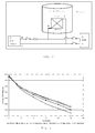
Fig. 1 illustrates transport of oxygen ions and electron flow during conventional SOFC operation. -
Fig. 2 illustrates electron flow during electrical protection of the anode with the aid of an external power supply unit. -
Fig. 3 illustrates the adjustment of cell voltages by subtraction of the production tolerances. -
Fig. 4 illustrates local leakage in a cell. -
Fig. 5 illustrates the test set-up with an external power supply connected to the set up. -
Fig. 6 illustrates characterization curves from the first thermal cycle. -
Fig. 7 illustrates stack voltage, fuel flow and electrolysis current as a function of time. -
Fig. 8 illustrates the resistance (ASR) as a function of time. -
Fig.9 illustrates the leak current(A)as a function of time. -
Fig. 10 shows an example of a simple natural gas based system during operation. -
Fig.11 shows the resistance (ASR) as a function of time. -
Fig.12 shows the Leak current (A) as a function of time. - An external potential may be applied to the fuel cell stack in the following situations:
- when it is being heated up without reducing gas on the anode i.e. no fuel or protection gas present
- during interrupted duty (so-called trips) of the system where power is not produced
- during hot stand-by situations which may be desired or accidental, where power is not produced
- during shut down of the system where the fuel cell is cooled down without a reducing gas on the anode
- If the fuel cell stack is at ambient temperature when the power supply unit is connected, then ramping of the voltage from 0 mV up to 700 mV or higher is not critical since the reoxidation rate is low and protection is not required immediately.
- If the fuel cell stack is not at ambient temperature when it is to be connected to the power supply unit, then it is important that the power supply unit is, prior to carrying out the connection, already ramped to 700 mV or higher. Thereby the fuel cell stack is protected immediately on connection to the power supply unit.
- It is therefore essential that the power supply unit is adjusted to provide a voltage of 700-1500 mV to the fuel cell stack prior to connecting the fuel cell stack.
- During normal SOFC operation the electrolyte transports oxygen-ions (O2-) from the cathode to the anode where they react with the fuel creating water and free electrons, and thereby a potential difference.
- The SOFC is thus the active unit where the voltage difference (U0) is created and which drives the flow of electrons from the anode (negative electrode) through the external circuit and load (passive unit) to the cathode (positive electrode) which is shown in
Fig. 1 . The load provides electrical resistance and causes a potential drop. The current runs in the opposite direction of the electrons i.e. from the cathode (+) to the anode (÷). - When carrying out the process of the invention the electrolyte in the SOFC is used to transport oxygen-ions (O2-) from the anode chamber to the cathode i.e. opposite of the normal operating mode.
- This is done by adding electrons to the anode and thereby ionizing the oxygen. The electrons are delivered by an external circuit where a Power Supply Unit (PSU) is driving the electrons to the anode of the SOFC. The PSU is thus the active unit in the circuit where the potential difference is created and which drives the electrons from (÷) to the anode "through" the stack (by O2- transport) and from the cathode to (+), which is shown in
fig. 2 . - The SOFC is the passive unit in the circuit, and though the electrons are running in the opposite direction - the anode is still negative and the cathode is positive and the polarity of the SOFC is the same. This is the case because the current is driven by the PSU and not the SOFC.
- To avoid anode re-oxidation the PSU must deliver enough electrons to the anode to keep the individual cell above the reduction potential of Ni to NiO, which is app. 700 mV. The reduction potential for Ni re-oxidation is the lower limit for the cell voltage during operation (700 mV) applied in the process of the invention.
- In the process of the invention electrons are supplied from the PSU to boost the cell voltages to a value above 700 mV which is the voltage during safe SOFC operation. The lower safe limit for the individual cell voltages is 700 mV whereby Ni re-oxidation is avoided, and the upper limit for the voltages is approx. 2000 mV corresponding to the risk of decomposing zirconium when the voltage exceeds 2000 mV.
- If Carbon Monoxide is present the upper limit for safe operation is the Carbon monoxide to Carbon reduction potential of
app 1500 mV. - An essential parameter in the inventive process is then to boost the cell voltage to a value between 700 mV and 1500 mV. The PSU as shown in
Fig. 2 with positive (+) to the cathode and negative (÷) to the anode. During start-up a constant protective voltage should be applied, by connecting the PSU, before stack temperature reaches 300°C. It can be applied at room temperature. - The voltage from the PSU may be approx. 1000 mV pr cell in the stack, but must be adjusted according to specific cell voltage measurements to keep all cell voltages between 700 and 1500 mV minus production tolerances as shown in
Fig. 3 . - The current is low at 300°C, but increases as the temperature increases. When the fuel cell stack is at operating temperature, then the operational flows can be applied to the stack, and the PSU turned off.
- During unexpected system failure of the SOFC system the PSU can be applied immediately when the SOFC is at open circuit voltage (OCV) and the external load is cut off. This means that no extra control is needed.
- During hot standby the PSU can be applied when the SOFC is at OCV. The fuel flow can then be turned off and the stack will be protected against re-oxidation. When the SOFC is to be brought back into service, the fuel is supplied and the PSU turned off.
- During Shut-down the PSU is applied when the SOFC is at OCV. The fuel flow is then turned off and the SOFC is cooled to room temperature. The PSU can be turned off when the SOFC is below 300°C (or at room temperature).
- By carrying out the process of the invention the anode of the SOFC is protected, which means that no protection gas (from bottle or produced in the system) is needed. The process provides quick protection in an easy manner, which ensure that the anode is protected at all times.
- The PSU can be connected to the trip system which monitors the SOFC system during operation and applied if any failure occurs (no fuel, low SOFC voltage, wrong temperatures or pressures, leaks, safety issues or other system components failure). This means that no extra control is needed when using the process of the invention for protection of the SOFC anode.
- The PSU can for instance be a battery, capacitor, AC/DC converter or another fuel cell, and must be able to provide the required voltage in order to maintain sufficient current.
- When applying the process of the invention there is no sign of degradation on any of the cells in the stack, indicating that it is possible to prevent damaging re-oxidation of the anode Ni to NiO using electrolysis current protection.
- The electrolysis current was aimed to be able to match the average leak current of the stack in order to remove all incoming oxygen from the anode. One of the cells (cell 6) had a leak current almost 3 times higher than the average leak current, but there were no signs of degradation of this cell, although it only received about one third of the theoretical needed protection current.
- Therefore it does not appear to be crucial to have a uniform distribution of the leak current through the stack to be able to protect the stack using electrolysis current. The test indicates that an electrolysis current of one third of the cells leak current is enough to protect the anode from re-oxidizing.
- If the process is carried out with a starting temperature corresponding to room temperature, the anode of the SOFC is protected against re-oxidation during the entire start-up. Fuel can be applied at any time after the operational temperature is reached and the PSU can then be turned off.
- The operation temperature is chosen according to the requirements of the fuel cell system design. Conventional operation temperatures of approximately 550 to 850°C are chosen.
- If the inventive process is carried out at room temperature and the power supply unit turned off at operating temperature when fuel is applied, no extra control is needed to handle the PSU, which simplifies the system.
- Because no protection gas is needed during start-up, the Fuel Processing System (FPS) which supplies fuel for the SOFC can be kept cold and inactive until the SOFC is at operating conditions. This means more freedom to operate the fuel processing system during start-up.
- During Trips or hot standby many protection systems monitor the SOFC voltage or the fuel pressure and apply protection if the voltage or pressure drops below a certain critical value. If the pressure or voltage drops below a "critical value" local failures can still occur in one or more individual fuel cells due to re-oxidation.
- The individual cell voltages can be monitored and even though the cell voltage of a single cell can be above the critical value, a local leakage on the cell will re-oxidize part of the cell, see
Fig. 4 . - This can be avoided by carrying out the inventive process immediately any failure occurs or if at hot stand-by, irrespective of the electromotive force of the fuel cell stack.
- The process of the invention is also carried out when the stack is at open circuit voltage (OCV) and it is desired to shut down the system. The connection to the power supply unit is maintained. Fuel is then cut off and the system is cooled down. The SOFC is thus protected at all times with no risk of any re-oxidation of any part of the cells because no part of the cells or stack is close or below the re-oxidation limit of approximately 700 mV.
- The PSU unit is turned off when the SOFC is below 300°C or at room temperature, as no control is needed and measurement of cell voltages is not necessary.
- In
Fig. 10 is shown an example of a simple natural gas based system during operation. - Natural Gas and water is fed to a pre-reformer, where the fuel is pre-reformed to a syngas comprising Hydrogen, Methane, Carbon Monoxide and Water. Any higher hydrocarbons present will also be converted to methane. The syngas is sent to the anode of the SOFC where it is consumed to produce electricity. Air is simultaneously sent to the cathode to participate in the reactions.
- During operation, some of the anode-off gas is recirculated to the pre-reformer to reuse the water produced in the SOFC and to recuperate some of the unused hydrogen.
- The remaining anode off gas not sent to the pre-reformer, is sent to the off gas-burner where it is combusted using excess cathode air.
- During emergency trips, shut-down or hot standby the SOFC anode and the pre-reformer need to be protected against re-oxidation.
- Normally the pre-reformer and SOFC are protected by sending an inert protection gas through the anode side of the system.
- Both the anode of the SOFC and the pre-reformer are protected by applying the process of the invention. The anode of the SOFC is directly protected against re-oxidation by the electric potential applied by the external Power Supply Unit (PSU).
- The pre-reformer (or any other Fuel Processing Unit) is protected against re-oxidation because the SOFC will produce hydrogen from the residual water present in the recycle loop. The residual water from the operation before the trip will immediately be electrolyzed into hydrogen by the solid oxide cell in electrolysis mode and recycled to the FPS.
- The electrolysis in the solid oxide cell can be controlled by keeping the voltage of the PSU constant in the "safe region" between 700 and 1500 mV per cell.
- If the system needs to be protected during a longer hot standby or trip, water can be supplied through the fuel processing system to the solid oxide cell (as during normal operation of a SOFC) and the electrolysis process in the solid oxide cell will keep producing protection gas comprising hydrogen.
- The system of recirculation of hydrogen produced by the SOFC stack can also be used for a Fuel Processing System where hydrogen is needed to process the fuel e.g. a reaction between sulphur and hydrogen to form H2S which can be absorbed.
- Other media apart from fuel and water can be added to the fuel processing system e.g. a mixture of steam and air or the separate addition of steam and air respectively.
- A standard stack consisting of 10 SOFC cells was heated to app. 800°C in a pilot plant using electrolysis current as protection against anode nickel re-oxidation. The stack was subjected to periods with anode protection using electrolysis current at 800 °C up to 63 hours. During the test, the stack was characterized with a standard IV-curve to 25 A. The characterizations showed no sign of degradation of any cell in the standard stack, indicating that it is possible to prevent damaging re-oxidation of the anode Ni to NiO using electrolysis current protection, see
fig. 6 to Fig. 9 . - The electrolysis current was aimed to be able to match the average leak current of the stack in order to remove all incoming oxygen to the anode. One of the cells (cell 6) had a leak current almost 3 times higher than the average leak current, but there were no signs of degradation of the cell, although it only received about one third of the theoretical needed protection current. Thus it did not appear crucial to have a uniform distribution of the leak current current through the stack to be able to protect the stack using electrolysis current. The test indicated that an electrolysis current of one third of the cells leak current is enough to protect the anode from re-oxidizing, see
fig. 6 to fig. 9 . - The stack was subjected to 4 thermal cycles where the stack was heated to app. 800°C, characterized and then cooled to app. 400°C. The anode was protected against re-oxidation by electrolysis current during heating up and cooling down. There was no change in ASR or leak current of the stack after 4 thermal cycles with electrolysis current protection of the anode. This indicates that electrolysis current protection is effective during start-up and shut-down, see
fig. 11 andfig. 12 . - In
US 2002/0028362 A1 a PSU is applied when the SOFC voltage or the fuel pressure drops below a "critical value". If the unit is applied when the voltage becomes too low, local failures can occur which are not detected and the power supply is applied too late". - Below are two examples of failures of the control in
US 0028362 : - The SOFC stack voltage in a 10 cell stack is used to control the PSU, and the critical voltage is set to 700 mV pr cell which equals 7 V for the SOFC stack.
- The individual voltages of the cells will vary depending on cell quality, local leaks etc. This means that a measured stack voltage of 7.7 V (which is above the critical limit) could be achieved by 9 cells with 800 mV and one cell with 500 mV ((9x0.8)+0.5 = 7.7).
- This means that the one cell with a voltage of 500 mV needs protection against re-oxidation, but no PSU will be applied until the entire stack voltage is below 7 V.
- The same applies when the control of the anode oxidation in
US 200028362 is the monitoring of individual cell voltages. The cell voltage can be above "the critical value" while a local leakage on the cell will re-oxidize part of the cell, as shown inFig. 3 . - The stack was heated up without protection gas, but with applied PSU current, then subjected to 4 periods of anode protection using PSU current at operational temperature before shut-down with PSU current as shown in
Fig. 7 . - The stack was characterized between every period with applied PSU current with a standard IV-curve to 25 A. These characterizations where made to compare performance of the stack with the test performed on the standard stack in pilot P5-046 and during the test with the process of the invention in pilot P1-084. The characterization-curves for the tests in pilots P5-046 and P1-084 nos.1-5 are shown in
Fig. 6 . - As can be seen in
Fig. 6 , the stack performance improves from P5-046 to P1-084UI# 1 and again to P1-084UI# 2 which are the two characterizations after start-up with electrolysis current and a period of 1 hour at operational temperature with applied protection current. - The performance of the stack is then the same for UI Nos. 2 to 5, showing that the anode protection with PSU current is effective during start-up and at operational temperature (800°C) for a period up to approx. 63 hours.
-
Fig. 8 shows the calculated minimum, maximum and average ASR at 25 A, standard conditions for the standard stack during the first thermal cycle with periods of anode protection using PSU current. It can be seen that the ASR is reduced from the initial test, and that the ASR is not significantly changed after periods with PSU current to protect the anode from re-oxidation. -
Fig. 9 shows the calculated leak current for the stack from the initial test in pilot P5-046 and during first thermal cycle in pilot P1-084. It can be seen that the average leak is almost constant during the test, indicating that no extra leakage caused by cracking of the anode has a cured.
Claims (6)
- Process for operating a high temperature fuel cell stack during interrupted duty (so-called "trips"), the process comprising the following steps:a) connecting the fuel cell stack in parallel to a power supply unit at a predefined temperature and/or voltage of the fuel cell stack,b) applying a voltage from the power supply unit of between 700 to 1500 mV per fuel cell across the fuel cell stack irrespective of the electromotive force of the fuel cell stack, andc) disconnecting the load on said fuel cell stack while maintaining the voltage per fuel cell from the power supply unit during said interrupted duty, irrespective of the electromotive force of the fuel cell stack.
- Process for operating a high temperature fuel cell stack during hot standby, the process comprising the following steps:a) connecting the fuel cell stack in parallel to a power supply unit at a predefined temperature and/or voltage of the fuel cell stack,b) applying a voltage from the power supply unit of between 700 to 1500 mV per fuel cell across the fuel cell stack irrespective of the electromotive force of the fuel cell stack,c) turning off the fuel flow to the fuel cell stack,d) disconnecting the load on said fuel cell stack while maintaining the voltage per fuel cell from the power supply unit during hot standby, irrespective of the electromotive force of the fuel cell stack, ande) when the fuel cell stack is to be brought back into service, the fuel is supplied and the power supply unit is turned off.
- Process according to claim 1 or 2, wherein the voltage from the power supply unit of between 700 to 1500 mV per fuel cell includes production tolerance.
- Process according to claim 3, wherein the voltage from the power supply unit is 1000 mV per fuel cell.
- Process according to anyone of claims 1-4, wherein the high temperature fuel cell is a molten carbonate fuel cell or a solid oxide cell.
- Process according to claim 5, wherein the solid oxide cell is a solid oxide fuel cell or a solid oxide electrolysis cell.
Priority Applications (1)
| Application Number | Priority Date | Filing Date | Title |
|---|---|---|---|
| EP14173801.3A EP2811568B1 (en) | 2010-05-05 | 2010-05-05 | Process for operating a high temperature fuel cell stack |
Applications Claiming Priority (3)
| Application Number | Priority Date | Filing Date | Title |
|---|---|---|---|
| PCT/EP2010/002765 WO2011137916A1 (en) | 2010-05-05 | 2010-05-05 | Process for operating a high temperature fuel cell stack |
| EP10723498.1A EP2567422B8 (en) | 2010-05-05 | 2010-05-05 | Process for operating a high temperature fuel cell stack |
| EP14173801.3A EP2811568B1 (en) | 2010-05-05 | 2010-05-05 | Process for operating a high temperature fuel cell stack |
Related Parent Applications (2)
| Application Number | Title | Priority Date | Filing Date |
|---|---|---|---|
| EP10723498.1A Division-Into EP2567422B8 (en) | 2010-05-05 | 2010-05-05 | Process for operating a high temperature fuel cell stack |
| EP10723498.1A Division EP2567422B8 (en) | 2010-05-05 | 2010-05-05 | Process for operating a high temperature fuel cell stack |
Publications (2)
| Publication Number | Publication Date |
|---|---|
| EP2811568A1 EP2811568A1 (en) | 2014-12-10 |
| EP2811568B1 true EP2811568B1 (en) | 2016-03-23 |
Family
ID=43530499
Family Applications (3)
| Application Number | Title | Priority Date | Filing Date |
|---|---|---|---|
| EP14173801.3A Active EP2811568B1 (en) | 2010-05-05 | 2010-05-05 | Process for operating a high temperature fuel cell stack |
| EP10723498.1A Active EP2567422B8 (en) | 2010-05-05 | 2010-05-05 | Process for operating a high temperature fuel cell stack |
| EP14173799.9A Active EP2811567B1 (en) | 2010-05-05 | 2010-05-05 | Process for operating a high temperature fuel cell stack |
Family Applications After (2)
| Application Number | Title | Priority Date | Filing Date |
|---|---|---|---|
| EP10723498.1A Active EP2567422B8 (en) | 2010-05-05 | 2010-05-05 | Process for operating a high temperature fuel cell stack |
| EP14173799.9A Active EP2811567B1 (en) | 2010-05-05 | 2010-05-05 | Process for operating a high temperature fuel cell stack |
Country Status (14)
| Country | Link |
|---|---|
| US (1) | US9005827B2 (en) |
| EP (3) | EP2811568B1 (en) |
| JP (1) | JP5738983B2 (en) |
| KR (1) | KR101753610B1 (en) |
| CN (1) | CN103026539B (en) |
| AU (1) | AU2010352713B2 (en) |
| BR (1) | BR112012028329A2 (en) |
| CA (1) | CA2798206A1 (en) |
| DK (1) | DK2567422T3 (en) |
| EA (1) | EA201291140A8 (en) |
| ES (1) | ES2508115T3 (en) |
| TW (1) | TW201218496A (en) |
| WO (1) | WO2011137916A1 (en) |
| ZA (1) | ZA201208278B (en) |
Families Citing this family (25)
| Publication number | Priority date | Publication date | Assignee | Title |
|---|---|---|---|---|
| GB2486001B (en) * | 2010-12-01 | 2012-11-21 | Rolls Royce Fuel Cell Systems Ltd | A solid oxide fuel cell system and a method of operating a solid oxide fuel cell system |
| CA2835385A1 (en) * | 2011-05-26 | 2012-11-29 | Thomas Heiredal-Clausen | Electrical anode reduction of solid oxide fuel cell |
| CN103855415B (en) * | 2012-11-29 | 2015-12-02 | 中国科学院大连化学物理研究所 | Method for restoring performance after a kind of direct alcohol fuel cell experience low temperature |
| WO2014108223A1 (en) | 2013-01-11 | 2014-07-17 | Topsøe Fuel Cell A/S | Method for regeneration of sulfur-poisoned fuel cell stacks |
| WO2014114348A1 (en) | 2013-01-25 | 2014-07-31 | Haldor Topsøe A/S | A process for monitoring, protection and safety shut-down of an electrolyser system |
| DE102013214056B4 (en) | 2013-07-17 | 2022-04-07 | Eberspächer Climate Control Systems GmbH & Co. KG | solid oxide fuel cell |
| JP6163386B2 (en) * | 2013-08-27 | 2017-07-12 | 三菱日立パワーシステムズ株式会社 | Fuel cell system and protection method thereof |
| JP2015069753A (en) * | 2013-09-27 | 2015-04-13 | 大阪瓦斯株式会社 | Solid oxide fuel cell system |
| WO2015116964A1 (en) | 2014-01-31 | 2015-08-06 | Fuelcell Energy, Inc. | Reformer-electrolyzer-purifier (rep) assembly for hydrogen production, systems incorporating same and method of producing hydrogen |
| EP2960977B1 (en) * | 2014-06-27 | 2019-12-18 | Haldor Topsøe A/S | Anode support creep |
| JP6679720B2 (en) | 2015-11-16 | 2020-04-15 | フュエルセル エナジー, インコーポレイテッドFuelcell Energy, Inc. | System for capturing CO2 from fuel cells |
| EP3425716A1 (en) * | 2015-11-16 | 2019-01-09 | Fuelcell Energy, Inc. | Energy storage using an rep with an engine |
| WO2017087518A1 (en) | 2015-11-17 | 2017-05-26 | Fuelcell Energy, Inc. | Hydrogen and carbon monoxide generation using an rep with partial oxidation |
| JP6650035B2 (en) | 2015-11-17 | 2020-02-19 | フュエルセル エナジー, インコーポレイテッドFuelcell Energy, Inc. | Fuel cell system with improved CO2 capture |
| DE102016204609A1 (en) * | 2016-03-21 | 2017-09-21 | Robert Bosch Gmbh | Method for operating a fuel cell device |
| CA3021733C (en) | 2016-04-21 | 2020-12-29 | Fuelcell Energy, Inc. | Fluidized catalytic cracking unit system with integrated reformer-electrolyzer-purifier |
| CN108091907B (en) | 2016-11-22 | 2020-09-25 | 通用电气公司 | Fuel cell system and shutdown method thereof |
| KR101892544B1 (en) * | 2017-01-20 | 2018-08-28 | 창원대학교 산학협력단 | Device for preventing oxidation of anode included in solid oxide fuel cell |
| US10897055B2 (en) | 2017-11-16 | 2021-01-19 | Fuelcell Energy, Inc. | Load following power generation and power storage using REP and PEM technology |
| US10483566B2 (en) | 2018-03-20 | 2019-11-19 | Cummins Enterprise Llc | Method and control sub-system for operating a power generation system having a fuel-cell |
| KR102598947B1 (en) * | 2018-05-04 | 2023-11-06 | 현대자동차주식회사 | Fuel cell system and method for controlling therof |
| US11495806B2 (en) | 2019-02-04 | 2022-11-08 | Fuelcell Energy, Inc. | Ultra high efficiency fuel cell power generation system |
| FR3117684B1 (en) | 2020-12-11 | 2023-03-31 | Commissariat Energie Atomique | Method of operating in hot standby mode of a SOFC fuel cell or a SOEC reactor. |
| TWI734657B (en) | 2021-01-15 | 2021-07-21 | 電聯運通股份有限公司 | Fuel cell energy recycling system |
| EP4123056B1 (en) | 2021-07-20 | 2024-01-17 | Topsoe A/S | Method for transient operation of a solid oxide electrolysis cell stack |
Family Cites Families (17)
| Publication number | Priority date | Publication date | Assignee | Title |
|---|---|---|---|---|
| JP2626395B2 (en) * | 1992-01-14 | 1997-07-02 | 三井造船株式会社 | Method for improving characteristics of high temperature solid oxide fuel cell |
| US20020028362A1 (en) | 2000-09-01 | 2002-03-07 | Dennis Prediger | Anode oxidation protection in a high-temperature fuel cell |
| DE10209309B4 (en) | 2002-03-02 | 2004-03-11 | Mtu Cfc Solutions Gmbh | Process for inerting the anodes of high-temperature fuel cells and high-temperature fuel cell arrangement |
| US20030235752A1 (en) | 2002-06-24 | 2003-12-25 | England Diane M. | Oxygen getters for anode protection in a solid-oxide fuel cell stack |
| US7432002B2 (en) * | 2002-09-30 | 2008-10-07 | E.I. Du Pont De Nemours And Company | Method for regeneration of performance in a fuel cell |
| US20040126632A1 (en) * | 2002-12-27 | 2004-07-01 | Pearson Martin T. | Regenerative fuel cell electric power plant and operating method |
| US7575822B2 (en) * | 2003-04-09 | 2009-08-18 | Bloom Energy Corporation | Method of optimizing operating efficiency of fuel cells |
| JP2004324060A (en) | 2003-04-21 | 2004-11-18 | Sekisui Chem Co Ltd | Regeneration method for manhole |
| JP5276318B2 (en) | 2004-04-15 | 2013-08-28 | ヴァーサ パワー システムズ リミテッド | Stop fuel cell by steam purge |
| US20060141300A1 (en) | 2004-12-27 | 2006-06-29 | Versa Power Systems, Ltd. | Preconditioning treatment to enhance redox tolerance of solid oxide fuel cells |
| US20060194082A1 (en) * | 2005-02-02 | 2006-08-31 | Ultracell Corporation | Systems and methods for protecting a fuel cell |
| US7700210B2 (en) * | 2005-05-10 | 2010-04-20 | Bloom Energy Corporation | Increasing thermal dissipation of fuel cell stacks under partial electrical load |
| DE102005059708A1 (en) | 2005-12-12 | 2007-06-14 | Forschungszentrum Jülich GmbH | Reoxidation stable high-temperature fuel cell |
| EP1986264A1 (en) * | 2007-04-26 | 2008-10-29 | Technische Universität München | System for generating electrical energy comprising an electrochemical reformer and a fuel cell |
| JP5081542B2 (en) | 2007-09-03 | 2012-11-28 | 本田技研工業株式会社 | Fuel cell system and operation method thereof |
| JP5001761B2 (en) | 2007-09-10 | 2012-08-15 | Jx日鉱日石エネルギー株式会社 | Steam generator and operating method of fuel cell system |
| US20090253007A1 (en) | 2008-04-04 | 2009-10-08 | Mergler Christopher M | Method and apparatus for anode oxidation prevention and cooling of a solid-oxide fuel cell stack |
-
2010
- 2010-05-05 BR BR112012028329A patent/BR112012028329A2/en not_active IP Right Cessation
- 2010-05-05 JP JP2013508374A patent/JP5738983B2/en active Active
- 2010-05-05 EP EP14173801.3A patent/EP2811568B1/en active Active
- 2010-05-05 EA EA201291140A patent/EA201291140A8/en unknown
- 2010-05-05 US US13/695,944 patent/US9005827B2/en active Active
- 2010-05-05 EP EP10723498.1A patent/EP2567422B8/en active Active
- 2010-05-05 EP EP14173799.9A patent/EP2811567B1/en active Active
- 2010-05-05 CN CN201080066611.6A patent/CN103026539B/en active Active
- 2010-05-05 KR KR1020127031744A patent/KR101753610B1/en active IP Right Grant
- 2010-05-05 AU AU2010352713A patent/AU2010352713B2/en not_active Ceased
- 2010-05-05 ES ES10723498.1T patent/ES2508115T3/en active Active
- 2010-05-05 WO PCT/EP2010/002765 patent/WO2011137916A1/en active Application Filing
- 2010-05-05 DK DK10723498.1T patent/DK2567422T3/en active
- 2010-05-05 CA CA2798206A patent/CA2798206A1/en not_active Abandoned
-
2011
- 2011-05-03 TW TW100115441A patent/TW201218496A/en unknown
-
2012
- 2012-11-05 ZA ZA2012/08278A patent/ZA201208278B/en unknown
Also Published As
| Publication number | Publication date |
|---|---|
| EP2567422B1 (en) | 2014-07-16 |
| TW201218496A (en) | 2012-05-01 |
| EP2567422A1 (en) | 2013-03-13 |
| KR101753610B1 (en) | 2017-07-04 |
| JP2013530490A (en) | 2013-07-25 |
| AU2010352713B2 (en) | 2014-07-31 |
| EP2811567A1 (en) | 2014-12-10 |
| CA2798206A1 (en) | 2011-11-10 |
| KR20130071435A (en) | 2013-06-28 |
| CN103026539B (en) | 2015-08-26 |
| ES2508115T3 (en) | 2014-10-16 |
| EA201291140A1 (en) | 2013-05-30 |
| BR112012028329A2 (en) | 2017-03-21 |
| DK2567422T3 (en) | 2014-10-27 |
| EP2567422B8 (en) | 2015-03-11 |
| US9005827B2 (en) | 2015-04-14 |
| EA201291140A8 (en) | 2014-02-28 |
| WO2011137916A1 (en) | 2011-11-10 |
| EP2811568A1 (en) | 2014-12-10 |
| JP5738983B2 (en) | 2015-06-24 |
| ZA201208278B (en) | 2014-01-29 |
| US20130052548A1 (en) | 2013-02-28 |
| CN103026539A (en) | 2013-04-03 |
| EP2811567B1 (en) | 2016-03-23 |
Similar Documents
| Publication | Publication Date | Title |
|---|---|---|
| EP2811568B1 (en) | Process for operating a high temperature fuel cell stack | |
| AU2010352713A1 (en) | Process for operating a high temperature fuel cell stack | |
| JP4961682B2 (en) | Fuel cell power generation apparatus and operation stop method | |
| US20020028362A1 (en) | Anode oxidation protection in a high-temperature fuel cell | |
| JP5456686B2 (en) | System and method for operating with high temperature fuel cell as standby power source with reduced performance degradation | |
| US6696190B2 (en) | Fuel cell system and method | |
| US20070154752A1 (en) | Starting up and shutting down a fuel cell stack | |
| JP2007287633A (en) | Fuel cell power generator and control program as well as control method | |
| EP2375484B1 (en) | Operating method of fuel cell system | |
| KR101782353B1 (en) | Freeze startup method for a fuel cell system | |
| JP2004172105A (en) | Operation method of fuel cell system and fuel cell system | |
| JP2009245693A (en) | Fuel cell power generation device, and control method and control program during stoppage | |
| EP3259795B1 (en) | Electrochemical oxidation of carbonaceous deposits in liquid-hydrocarbon fueled solid oxide fuel cells | |
| JP2004172106A (en) | Operation method of fuel cell system and fuel cell system | |
| KR101892544B1 (en) | Device for preventing oxidation of anode included in solid oxide fuel cell | |
| EP4020640A1 (en) | Fuel cell system and method for controlling fuel cell system | |
| KR101435394B1 (en) | Fuel cell operation system system and method | |
| JP2007066582A (en) | Control method of fuel cell, its control device, and vehicle mounting control device | |
| JP2008135204A (en) | Fuel-cell power generator, and its control method/control program | |
| JP2009245692A (en) | Fuel cell power generation device, flow passage abnormal condition detection method of oxidizer gas, and flow passage abnormal condition detection program | |
| KR20070093279A (en) | Fuel cell using performance restoration apparatus | |
| JP2007335354A (en) | Power generating device for fuel cell, and degradation state diagnosting method of fuel cell stack |
Legal Events
| Date | Code | Title | Description |
|---|---|---|---|
| PUAI | Public reference made under article 153(3) epc to a published international application that has entered the european phase |
Free format text: ORIGINAL CODE: 0009012 |
|
| 17P | Request for examination filed |
Effective date: 20140625 |
|
| AC | Divisional application: reference to earlier application |
Ref document number: 2567422 Country of ref document: EP Kind code of ref document: P |
|
| AK | Designated contracting states |
Kind code of ref document: A1 Designated state(s): AL AT BE BG CH CY CZ DE DK EE ES FI FR GB GR HR HU IE IS IT LI LT LU LV MC MK MT NL NO PL PT RO SE SI SK SM TR |
|
| RAP1 | Party data changed (applicant data changed or rights of an application transferred) |
Owner name: TECHNICAL UNIVERSITY OF DENMARK Owner name: HALDOR TOPSOEE A/S |
|
| R17P | Request for examination filed (corrected) |
Effective date: 20150410 |
|
| RBV | Designated contracting states (corrected) |
Designated state(s): AL AT BE BG CH CY CZ DE DK EE ES FI FR GB GR HR HU IE IS IT LI LT LU LV MC MK MT NL NO PL PT RO SE SI SK SM TR |
|
| RIC1 | Information provided on ipc code assigned before grant |
Ipc: H01M 8/06 20060101ALN20150820BHEP Ipc: H01M 8/12 20060101ALN20150820BHEP Ipc: H01M 8/04 20060101AFI20150820BHEP Ipc: H01M 8/14 20060101ALN20150820BHEP |
|
| RAP1 | Party data changed (applicant data changed or rights of an application transferred) |
Owner name: HALDOR TOPSOEE A/S Owner name: TECHNICAL UNIVERSITY OF DENMARK |
|
| GRAP | Despatch of communication of intention to grant a patent |
Free format text: ORIGINAL CODE: EPIDOSNIGR1 |
|
| INTG | Intention to grant announced |
Effective date: 20151016 |
|
| GRAS | Grant fee paid |
Free format text: ORIGINAL CODE: EPIDOSNIGR3 |
|
| GRAA | (expected) grant |
Free format text: ORIGINAL CODE: 0009210 |
|
| AC | Divisional application: reference to earlier application |
Ref document number: 2567422 Country of ref document: EP Kind code of ref document: P |
|
| AK | Designated contracting states |
Kind code of ref document: B1 Designated state(s): AL AT BE BG CH CY CZ DE DK EE ES FI FR GB GR HR HU IE IS IT LI LT LU LV MC MK MT NL NO PL PT RO SE SI SK SM TR |
|
| REG | Reference to a national code |
Ref country code: GB Ref legal event code: FG4D |
|
| REG | Reference to a national code |
Ref country code: CH Ref legal event code: EP |
|
| REG | Reference to a national code |
Ref country code: AT Ref legal event code: REF Ref document number: 783942 Country of ref document: AT Kind code of ref document: T Effective date: 20160415 |
|
| REG | Reference to a national code |
Ref country code: IE Ref legal event code: FG4D |
|
| REG | Reference to a national code |
Ref country code: DE Ref legal event code: R096 Ref document number: 602010031534 Country of ref document: DE |
|
| REG | Reference to a national code |
Ref country code: LT Ref legal event code: MG4D |
|
| REG | Reference to a national code |
Ref country code: NL Ref legal event code: MP Effective date: 20160323 |
|
| PG25 | Lapsed in a contracting state [announced via postgrant information from national office to epo] |
Ref country code: NO Free format text: LAPSE BECAUSE OF FAILURE TO SUBMIT A TRANSLATION OF THE DESCRIPTION OR TO PAY THE FEE WITHIN THE PRESCRIBED TIME-LIMIT Effective date: 20160623 Ref country code: GR Free format text: LAPSE BECAUSE OF FAILURE TO SUBMIT A TRANSLATION OF THE DESCRIPTION OR TO PAY THE FEE WITHIN THE PRESCRIBED TIME-LIMIT Effective date: 20160624 Ref country code: FI Free format text: LAPSE BECAUSE OF FAILURE TO SUBMIT A TRANSLATION OF THE DESCRIPTION OR TO PAY THE FEE WITHIN THE PRESCRIBED TIME-LIMIT Effective date: 20160323 Ref country code: HR Free format text: LAPSE BECAUSE OF FAILURE TO SUBMIT A TRANSLATION OF THE DESCRIPTION OR TO PAY THE FEE WITHIN THE PRESCRIBED TIME-LIMIT Effective date: 20160323 |
|
| REG | Reference to a national code |
Ref country code: AT Ref legal event code: MK05 Ref document number: 783942 Country of ref document: AT Kind code of ref document: T Effective date: 20160323 |
|
| PG25 | Lapsed in a contracting state [announced via postgrant information from national office to epo] |
Ref country code: SE Free format text: LAPSE BECAUSE OF FAILURE TO SUBMIT A TRANSLATION OF THE DESCRIPTION OR TO PAY THE FEE WITHIN THE PRESCRIBED TIME-LIMIT Effective date: 20160323 Ref country code: LT Free format text: LAPSE BECAUSE OF FAILURE TO SUBMIT A TRANSLATION OF THE DESCRIPTION OR TO PAY THE FEE WITHIN THE PRESCRIBED TIME-LIMIT Effective date: 20160323 Ref country code: BE Free format text: LAPSE BECAUSE OF NON-PAYMENT OF DUE FEES Effective date: 20160531 Ref country code: NL Free format text: LAPSE BECAUSE OF FAILURE TO SUBMIT A TRANSLATION OF THE DESCRIPTION OR TO PAY THE FEE WITHIN THE PRESCRIBED TIME-LIMIT Effective date: 20160323 Ref country code: LV Free format text: LAPSE BECAUSE OF FAILURE TO SUBMIT A TRANSLATION OF THE DESCRIPTION OR TO PAY THE FEE WITHIN THE PRESCRIBED TIME-LIMIT Effective date: 20160323 |
|
| PG25 | Lapsed in a contracting state [announced via postgrant information from national office to epo] |
Ref country code: PL Free format text: LAPSE BECAUSE OF FAILURE TO SUBMIT A TRANSLATION OF THE DESCRIPTION OR TO PAY THE FEE WITHIN THE PRESCRIBED TIME-LIMIT Effective date: 20160323 Ref country code: EE Free format text: LAPSE BECAUSE OF FAILURE TO SUBMIT A TRANSLATION OF THE DESCRIPTION OR TO PAY THE FEE WITHIN THE PRESCRIBED TIME-LIMIT Effective date: 20160323 Ref country code: IS Free format text: LAPSE BECAUSE OF FAILURE TO SUBMIT A TRANSLATION OF THE DESCRIPTION OR TO PAY THE FEE WITHIN THE PRESCRIBED TIME-LIMIT Effective date: 20160723 |
|
| PG25 | Lapsed in a contracting state [announced via postgrant information from national office to epo] |
Ref country code: ES Free format text: LAPSE BECAUSE OF FAILURE TO SUBMIT A TRANSLATION OF THE DESCRIPTION OR TO PAY THE FEE WITHIN THE PRESCRIBED TIME-LIMIT Effective date: 20160323 Ref country code: CZ Free format text: LAPSE BECAUSE OF FAILURE TO SUBMIT A TRANSLATION OF THE DESCRIPTION OR TO PAY THE FEE WITHIN THE PRESCRIBED TIME-LIMIT Effective date: 20160323 Ref country code: PT Free format text: LAPSE BECAUSE OF FAILURE TO SUBMIT A TRANSLATION OF THE DESCRIPTION OR TO PAY THE FEE WITHIN THE PRESCRIBED TIME-LIMIT Effective date: 20160725 Ref country code: AT Free format text: LAPSE BECAUSE OF FAILURE TO SUBMIT A TRANSLATION OF THE DESCRIPTION OR TO PAY THE FEE WITHIN THE PRESCRIBED TIME-LIMIT Effective date: 20160323 Ref country code: SK Free format text: LAPSE BECAUSE OF FAILURE TO SUBMIT A TRANSLATION OF THE DESCRIPTION OR TO PAY THE FEE WITHIN THE PRESCRIBED TIME-LIMIT Effective date: 20160323 Ref country code: SM Free format text: LAPSE BECAUSE OF FAILURE TO SUBMIT A TRANSLATION OF THE DESCRIPTION OR TO PAY THE FEE WITHIN THE PRESCRIBED TIME-LIMIT Effective date: 20160323 Ref country code: RO Free format text: LAPSE BECAUSE OF FAILURE TO SUBMIT A TRANSLATION OF THE DESCRIPTION OR TO PAY THE FEE WITHIN THE PRESCRIBED TIME-LIMIT Effective date: 20160323 |
|
| PG25 | Lapsed in a contracting state [announced via postgrant information from national office to epo] |
Ref country code: LU Free format text: LAPSE BECAUSE OF FAILURE TO SUBMIT A TRANSLATION OF THE DESCRIPTION OR TO PAY THE FEE WITHIN THE PRESCRIBED TIME-LIMIT Effective date: 20160505 Ref country code: IT Free format text: LAPSE BECAUSE OF FAILURE TO SUBMIT A TRANSLATION OF THE DESCRIPTION OR TO PAY THE FEE WITHIN THE PRESCRIBED TIME-LIMIT Effective date: 20160323 Ref country code: BE Free format text: LAPSE BECAUSE OF FAILURE TO SUBMIT A TRANSLATION OF THE DESCRIPTION OR TO PAY THE FEE WITHIN THE PRESCRIBED TIME-LIMIT Effective date: 20160323 |
|
| REG | Reference to a national code |
Ref country code: CH Ref legal event code: PL |
|
| REG | Reference to a national code |
Ref country code: DE Ref legal event code: R097 Ref document number: 602010031534 Country of ref document: DE |
|
| PLBE | No opposition filed within time limit |
Free format text: ORIGINAL CODE: 0009261 |
|
| STAA | Information on the status of an ep patent application or granted ep patent |
Free format text: STATUS: NO OPPOSITION FILED WITHIN TIME LIMIT |
|
| PG25 | Lapsed in a contracting state [announced via postgrant information from national office to epo] |
Ref country code: LI Free format text: LAPSE BECAUSE OF NON-PAYMENT OF DUE FEES Effective date: 20160531 Ref country code: DK Free format text: LAPSE BECAUSE OF FAILURE TO SUBMIT A TRANSLATION OF THE DESCRIPTION OR TO PAY THE FEE WITHIN THE PRESCRIBED TIME-LIMIT Effective date: 20160323 Ref country code: CH Free format text: LAPSE BECAUSE OF NON-PAYMENT OF DUE FEES Effective date: 20160531 |
|
| REG | Reference to a national code |
Ref country code: IE Ref legal event code: MM4A |
|
| PG25 | Lapsed in a contracting state [announced via postgrant information from national office to epo] |
Ref country code: BG Free format text: LAPSE BECAUSE OF FAILURE TO SUBMIT A TRANSLATION OF THE DESCRIPTION OR TO PAY THE FEE WITHIN THE PRESCRIBED TIME-LIMIT Effective date: 20160623 |
|
| 26N | No opposition filed |
Effective date: 20170102 |
|
| REG | Reference to a national code |
Ref country code: FR Ref legal event code: ST Effective date: 20170131 |
|
| PG25 | Lapsed in a contracting state [announced via postgrant information from national office to epo] |
Ref country code: FR Free format text: LAPSE BECAUSE OF NON-PAYMENT OF DUE FEES Effective date: 20160531 |
|
| PG25 | Lapsed in a contracting state [announced via postgrant information from national office to epo] |
Ref country code: IE Free format text: LAPSE BECAUSE OF NON-PAYMENT OF DUE FEES Effective date: 20160505 Ref country code: SI Free format text: LAPSE BECAUSE OF FAILURE TO SUBMIT A TRANSLATION OF THE DESCRIPTION OR TO PAY THE FEE WITHIN THE PRESCRIBED TIME-LIMIT Effective date: 20160323 |
|
| PG25 | Lapsed in a contracting state [announced via postgrant information from national office to epo] |
Ref country code: HU Free format text: LAPSE BECAUSE OF FAILURE TO SUBMIT A TRANSLATION OF THE DESCRIPTION OR TO PAY THE FEE WITHIN THE PRESCRIBED TIME-LIMIT; INVALID AB INITIO Effective date: 20100505 |
|
| PG25 | Lapsed in a contracting state [announced via postgrant information from national office to epo] |
Ref country code: MC Free format text: LAPSE BECAUSE OF FAILURE TO SUBMIT A TRANSLATION OF THE DESCRIPTION OR TO PAY THE FEE WITHIN THE PRESCRIBED TIME-LIMIT Effective date: 20160323 Ref country code: MK Free format text: LAPSE BECAUSE OF FAILURE TO SUBMIT A TRANSLATION OF THE DESCRIPTION OR TO PAY THE FEE WITHIN THE PRESCRIBED TIME-LIMIT Effective date: 20160323 Ref country code: MT Free format text: LAPSE BECAUSE OF NON-PAYMENT OF DUE FEES Effective date: 20160531 Ref country code: CY Free format text: LAPSE BECAUSE OF FAILURE TO SUBMIT A TRANSLATION OF THE DESCRIPTION OR TO PAY THE FEE WITHIN THE PRESCRIBED TIME-LIMIT Effective date: 20160323 |
|
| PG25 | Lapsed in a contracting state [announced via postgrant information from national office to epo] |
Ref country code: TR Free format text: LAPSE BECAUSE OF FAILURE TO SUBMIT A TRANSLATION OF THE DESCRIPTION OR TO PAY THE FEE WITHIN THE PRESCRIBED TIME-LIMIT Effective date: 20160323 Ref country code: AL Free format text: LAPSE BECAUSE OF FAILURE TO SUBMIT A TRANSLATION OF THE DESCRIPTION OR TO PAY THE FEE WITHIN THE PRESCRIBED TIME-LIMIT Effective date: 20160323 |
|
| P01 | Opt-out of the competence of the unified patent court (upc) registered |
Effective date: 20230602 |
|
| PGFP | Annual fee paid to national office [announced via postgrant information from national office to epo] |
Ref country code: DE Payment date: 20230530 Year of fee payment: 14 |
|
| PGFP | Annual fee paid to national office [announced via postgrant information from national office to epo] |
Ref country code: GB Payment date: 20230523 Year of fee payment: 14 |