EP2811495B1 - Transformer - Google Patents
Transformer Download PDFInfo
- Publication number
- EP2811495B1 EP2811495B1 EP13170704.4A EP13170704A EP2811495B1 EP 2811495 B1 EP2811495 B1 EP 2811495B1 EP 13170704 A EP13170704 A EP 13170704A EP 2811495 B1 EP2811495 B1 EP 2811495B1
- Authority
- EP
- European Patent Office
- Prior art keywords
- transformer
- magnetic
- return path
- magnetic core
- gap
- Prior art date
- Legal status (The legal status is an assumption and is not a legal conclusion. Google has not performed a legal analysis and makes no representation as to the accuracy of the status listed.)
- Not-in-force
Links
- 238000004804 winding Methods 0.000 claims description 17
- 239000000463 material Substances 0.000 claims description 13
- 229940024548 aluminum oxide Drugs 0.000 claims description 2
- TWNQGVIAIRXVLR-UHFFFAOYSA-N oxo(oxoalumanyloxy)alumane Chemical compound O=[Al]O[Al]=O TWNQGVIAIRXVLR-UHFFFAOYSA-N 0.000 claims description 2
- 229910010293 ceramic material Inorganic materials 0.000 claims 2
- 239000003822 epoxy resin Substances 0.000 claims 1
- 229920000647 polyepoxide Polymers 0.000 claims 1
- 239000004593 Epoxy Substances 0.000 description 4
- 239000000919 ceramic Substances 0.000 description 3
- 230000004907 flux Effects 0.000 description 3
- 230000035699 permeability Effects 0.000 description 3
- 239000000696 magnetic material Substances 0.000 description 2
- 238000004382 potting Methods 0.000 description 2
- 125000006850 spacer group Chemical group 0.000 description 2
- 239000004020 conductor Substances 0.000 description 1
- 230000001419 dependent effect Effects 0.000 description 1
- 238000010292 electrical insulation Methods 0.000 description 1
- 238000005538 encapsulation Methods 0.000 description 1
- 230000007613 environmental effect Effects 0.000 description 1
- 230000017525 heat dissipation Effects 0.000 description 1
- 239000002184 metal Substances 0.000 description 1
- 239000007769 metal material Substances 0.000 description 1
- 239000005300 metallic glass Substances 0.000 description 1
- 238000000034 method Methods 0.000 description 1
- 238000003466 welding Methods 0.000 description 1
Images
Classifications
-
- H—ELECTRICITY
- H01—ELECTRIC ELEMENTS
- H01F—MAGNETS; INDUCTANCES; TRANSFORMERS; SELECTION OF MATERIALS FOR THEIR MAGNETIC PROPERTIES
- H01F3/00—Cores, Yokes, or armatures
- H01F3/10—Composite arrangements of magnetic circuits
- H01F3/12—Magnetic shunt paths
-
- H—ELECTRICITY
- H01—ELECTRIC ELEMENTS
- H01F—MAGNETS; INDUCTANCES; TRANSFORMERS; SELECTION OF MATERIALS FOR THEIR MAGNETIC PROPERTIES
- H01F27/00—Details of transformers or inductances, in general
- H01F27/02—Casings
- H01F27/022—Encapsulation
-
- H—ELECTRICITY
- H01—ELECTRIC ELEMENTS
- H01F—MAGNETS; INDUCTANCES; TRANSFORMERS; SELECTION OF MATERIALS FOR THEIR MAGNETIC PROPERTIES
- H01F38/00—Adaptations of transformers or inductances for specific applications or functions
- H01F38/12—Ignition, e.g. for IC engines
Definitions
- This disclosure relates to a transformer and has particular, but not exclusive application, to a transformer for an ignition apparatus or coil, such as for, but not limited to, automotive applications.
- the transformers generally include a core of magnetic highly permeable material, around which primary and secondary windings are located.
- a closed magnetic return path is provided by a generally C or U shaped magnetic return path element, the magnetic core being located between two end faces of the return path element.
- Preferred materials for the magnetic core and for the magnetic return path element are laminated metal sheets.
- one end of the magnetic core directly abuts or contacts one end face of the magnetic return path element.
- a magnet or simply an air-gap Between the other end face of the magnetic return path element and the other end of the core is typically located a magnet or simply an air-gap.
- Magnetic saturation zones can be created at interfaces between the magnetic return path element and the magnetic core. Saturation is built-up inside the magnetic return path element, around the interface region to the magnetic core. Generally such saturation causes a problem in that it limits the performance of the entire magnetic circuit.
- Known solutions are to increase the cross-sections of the magnetic path element or use magnetic material with higher magnetic permeability. Either solution is not desired because it increases weight, volume and/or cost.
- Documents US 2004/085174A1 and US 2004/085173A1 disclose a transformer device comprising bulk amorphous metal.
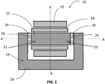
- Figure 1 shows a simple transformer according to one embodiment of the invention.
- the transformer comprises a magnetic core 12, a primary winding 14 and secondary winding 16, a magnetic return path element 18 and a first gap component 30.
- the magnetic core 12 extending along a longitudinal axis 'A' is generally cylindrical in overall shape and includes two ends 20 and 22.
- the magnetic return path element 18 is configured to provide a high permeability magnetic return path, and has a base section 24 and two end faces 26 and 28.
- the typical width for gap component 30 is 0.5 to 2 mm. Gap components could have different thickness.
- a second gap component 34 is located symmetrically to the first gap component 30. More precisely, the first and the second gap component 30 and 34 are located between each end faces of section 26 and 28 of the magnetic return path element 18 and the respective ends 20 and 22 of the magnetic core 12.
- the magnetic core 12 in combination with the magnetic return path element 18, and gap components form a magnetic circuit having a high magnetic permeability.
- the two gap components 30 and 34 may be formed from ceramic or other material. Preferably this material has a heat conductivity greater than 1 W/m/K.
- the choice of using heat conducting material for one or two gap components 30 and 34 can be selected to dissipate heat generated by the primary winding 14 and the secondary winding 16 from the magnetic core 12 to the magnetic return path element 18 either with a preferential direction or symmetrically.
- the gap components 30 and 34 are formed from materials such as ceramics; for example ceramics including aluminum-oxide, aluminum-nitrides or any similar materials.
- the additional second gap component 34 arranged symmetrically about the transverse axis 'B' to the first gap component 30 in the magnetic core 12, allows balancing of the magnetic circuit and by this allows an increase the total flux of the circuit.
- one gap component could be realized by a permanent magnetic material, whereas the second gap could be made out of any filling material, preferably with high thermal conductivity.
- This transformer topology increases the output performance of the transformer 10 and provides for a smaller more compact transformer.
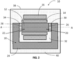
- FIG. 2 shows a transformer according to another embodiment of the invention.
- the transformer comprises again a magnetic core 12, a primary winding 14 and secondary winding 16, a magnetic return path element 18 and two gap components 30 and 34.
- the transformer is encapsulated within e.g. an epoxy material 32 with typical heat conductivities in the range of 0.1 to 1 W/m/K, to provide electrical insulation.
- the two gap components 30 and 34 encapsulated inside the epoxy 32 potting material may be provided by spacers.
- the two gap components allow balancing of the magnetic circuit and by this allow an increase the total flux of the circuit.
- the spacers provide the advantage of a lighter transformer.
- the epoxy potting material 32 also provides protection from environmental factors which may be encountered during the service life of the transformer. During the operation of the transformer 10, heat is created dominantly by ohmic losses of the primary winding 14 and secondary winding 16. This heat is conducted through the epoxy 32 encapsulation of the transformer to the surface.
- the transformer 10 mays have an insulating plastic housing 38 in order to attach, for instance, connectors. This transformer topology increases the output performance of the transformer 10 or to further miniaturize its magnetic circuit.
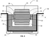
- FIG. 3 illustrates a further refined and preferred embodiment of the invention.
- the drawing shows similar components and reference numerals as before.
- the embodiment further however includes a heat sink 36 and an electronic circuit board 40.
- the heat sink 36 may be attached to the magnetic return path element 18 providing a large surface to reduce the internal temperature of the primary winding 14 and secondary winding 16 during transformer operation.
- the heat sink 36 can be attached by means of an over-mold, welding, clamping directly or any similar method, to the magnetic return path element18.
- the heat sink 36 is preferably made of magnetic or non-magnetic metal material and allows heat to flow outside of the plastic housing 38.
- the heat sink 36 may have additional means to attach to an integrated electronic circuit board 40 and serves by this for dissipating the heat from the electronic circuit board 40.
- the electronic circuit board is preferably used as an electronic control board for the ignition coil comprising the transformer 10.
- the heat sink 36 may further be formed as a bracket that can be fixed to a vehicle chassis.
- the bracket can be split into at least two individual elements.
- the thickness and contact surface of the heat sink 36 can be varied so as to provide desired heat dissipation requirements.
- the shape of the heat sink 36 is preferably conforms to the shape of the outer surface of the magnetic return path element 18.
- ignition coil topology allows balancing the magnetic circuit and by this allows increasing the total flux of the circuit. This can be used either to increase the output performance or to further miniaturize the magnetic circuit
Landscapes
- Engineering & Computer Science (AREA)
- Power Engineering (AREA)
- Chemical & Material Sciences (AREA)
- Composite Materials (AREA)
- Ignition Installations For Internal Combustion Engines (AREA)
- Coils Or Transformers For Communication (AREA)
Description
- This disclosure relates to a transformer and has particular, but not exclusive application, to a transformer for an ignition apparatus or coil, such as for, but not limited to, automotive applications.
- Conventional ignition coils are realized with gapped transformers. The transformers generally include a core of magnetic highly permeable material, around which primary and secondary windings are located. A closed magnetic return path is provided by a generally C or U shaped magnetic return path element, the magnetic core being located between two end faces of the return path element. Preferred materials for the magnetic core and for the magnetic return path element are laminated metal sheets.
- Typically, one end of the magnetic core directly abuts or contacts one end face of the magnetic return path element. Between the other end face of the magnetic return path element and the other end of the core is typically located a magnet or simply an air-gap. During the operation of such a coil transformer, heat is created dominantly by ohmic losses in the primary and secondary winding.
- Magnetic saturation zones can be created at interfaces between the magnetic return path element and the magnetic core. Saturation is built-up inside the magnetic return path element, around the interface region to the magnetic core. Generally such saturation causes a problem in that it limits the performance of the entire magnetic circuit. Known solutions are to increase the cross-sections of the magnetic path element or use magnetic material with higher magnetic permeability. Either solution is not desired because it increases weight, volume and/or cost. Documents
US 2004/085174A1 andUS 2004/085173A1 disclose a transformer device comprising bulk amorphous metal. - It is an object of the invention to provide an improved transformer that overcomes such problems.
- According to the present invention there is provided a transformer according to present claim 1. Preferred features are specified in dependent claims 2 to 13.
- Further features, uses and advantages of the invention will appear more clearly on a reading of the following detailed description of the embodiments of the invention, which is given by way of non-limiting example only and with reference to the accompanying drawings.
- This invention will be further described by way of example and with reference to the accompanying drawings in which:
-
Figure 1 shows a schematic longitudinal section through transformer of an ignition coil, in accordance with one basic example of the invention. -
Figure 2 shows a schematic longitudinal section through transformer of an ignition coil, in accordance with a further example of the invention. -
Figure 3 shows a schematic longitudinal section through transformer of an ignition coil, in accordance with another example of the invention. -
Figure 1 shows a simple transformer according to one embodiment of the invention. The transformer comprises amagnetic core 12, aprimary winding 14 andsecondary winding 16, a magneticreturn path element 18 and afirst gap component 30. Themagnetic core 12 extending along a longitudinal axis 'A' is generally cylindrical in overall shape and includes twoends return path element 18 is configured to provide a high permeability magnetic return path, and has abase section 24 and twoend faces gap component 30 is 0.5 to 2 mm. Gap components could have different thickness. - A
second gap component 34 is located symmetrically to thefirst gap component 30. More precisely, the first and thesecond gap component section return path element 18 and therespective ends magnetic core 12. Themagnetic core 12 in combination with the magneticreturn path element 18, and gap components form a magnetic circuit having a high magnetic permeability. - The two
gap components gap components primary winding 14 and thesecondary winding 16 from themagnetic core 12 to the magneticreturn path element 18 either with a preferential direction or symmetrically. Preferably thegap components second gap component 34, arranged symmetrically about the transverse axis 'B' to thefirst gap component 30 in themagnetic core 12, allows balancing of the magnetic circuit and by this allows an increase the total flux of the circuit. As an example, one gap component could be realized by a permanent magnetic material, whereas the second gap could be made out of any filling material, preferably with high thermal conductivity. This transformer topology increases the output performance of thetransformer 10 and provides for a smaller more compact transformer. -
Figure 2 shows a transformer according to another embodiment of the invention. The transformer comprises again amagnetic core 12, aprimary winding 14 andsecondary winding 16, a magneticreturn path element 18 and twogap components epoxy material 32 with typical heat conductivities in the range of 0.1 to 1 W/m/K, to provide electrical insulation. The twogap components epoxy 32 potting material may be provided by spacers. The two gap components allow balancing of the magnetic circuit and by this allow an increase the total flux of the circuit. The spacers provide the advantage of a lighter transformer. - The
epoxy potting material 32 also provides protection from environmental factors which may be encountered during the service life of the transformer. During the operation of thetransformer 10, heat is created dominantly by ohmic losses of the primary winding 14 andsecondary winding 16. This heat is conducted through theepoxy 32 encapsulation of the transformer to the surface. Thetransformer 10 mays have an insulatingplastic housing 38 in order to attach, for instance, connectors. This transformer topology increases the output performance of thetransformer 10 or to further miniaturize its magnetic circuit. -
Figure 3 illustrates a further refined and preferred embodiment of the invention. The drawing shows similar components and reference numerals as before. The embodiment further however includes aheat sink 36 and anelectronic circuit board 40. - The
heat sink 36 may be attached to the magneticreturn path element 18 providing a large surface to reduce the internal temperature of theprimary winding 14 andsecondary winding 16 during transformer operation. Theheat sink 36 can be attached by means of an over-mold, welding, clamping directly or any similar method, to the magnetic return path element18. Theheat sink 36 is preferably made of magnetic or non-magnetic metal material and allows heat to flow outside of theplastic housing 38. Theheat sink 36 may have additional means to attach to an integratedelectronic circuit board 40 and serves by this for dissipating the heat from theelectronic circuit board 40. The electronic circuit board is preferably used as an electronic control board for the ignition coil comprising thetransformer 10. - The
heat sink 36 may further be formed as a bracket that can be fixed to a vehicle chassis. Optionally the bracket can be split into at least two individual elements. The thickness and contact surface of theheat sink 36 can be varied so as to provide desired heat dissipation requirements. The shape of theheat sink 36 is preferably conforms to the shape of the outer surface of the magneticreturn path element 18. Within the invention, ignition coil topology allows balancing the magnetic circuit and by this allows increasing the total flux of the circuit. This can be used either to increase the output performance or to further miniaturize the magnetic circuit
Claims (13)
- A transformer (10) comprising:a magnetic core (12) extending along a longitudinal axis (A), being cylindrical in overall shape and including two ends (20, 22) forming two opposite radial surfaces;a U shaped magnetic return path element (18) having a base (24) and two legs and providing a magnetic return path for the magnetic core (12); said magnetic core (12) being located between two internal end faces (26,28) of the two legs of the U shaped magnetic return path element (18);a primary coil or winding (14), surrounding the magnetic core (12);a secondary coil or winding (16) surrounding the primary winding/coil (14);a first gap component (30) located between one end (20) of the magnetic core (12) and one corresponding internal end face (26) of the magnetic return path element (18);a second gap component (34) is located between the other end (22) of the magnetic core (12) and the corresponding other internal end face (28) of the magnetic return path element (18).
- A transformer (10) as claimed in claim 1 wherein said second gap component (34) is located symmetrically to the first gap component (30) in the magnetic core (12) about an axis perpendicular to the core axis.
- A transformer (10) as claimed in any previous claims wherein the magnetic core (12), the magnetic return path element (18), the primary winding (14) and the secondary winding (16) are encapsulated.
- A transformer (10) as claimed in claim 3 wherein the encapsulating material is an epoxy resin (32).
- A transformer (10) as claimed in any previous claims wherein at least one of the gap components (30, 34) is formed from an electrical isolating material.
- A transformer (10) as claimed in any previous claims wherein at least one of the gap components (30, 34) are formed from a material with a thermal conductivity greater than 1 W/m/K.
- A transformer (10) as set in any of previous claims wherein the two gap components (30, 34) are formed from a ceramic material.
- A transformer (10) as claimed in claim 7 wherein said ceramic material includes aluminum-oxide or aluminum-nitrides.
- A transformer (10) as claimed in any of previous claims further including a heat sink (36) surrounding a substantial portion of said transformer (10).
- A transformer (10) as claimed in claim 9 wherein said heat sink includes a bracket.
- A transformer (10) as claimed in claims 9 or 10 wherein an electronic board (40) is attached to the heat sink (36).
- A transformer (10) as claimed in any of previous claims including an insulating housing (38).
- An ignition coil including a transformer (10) as claimed in any preceding claim.
Priority Applications (1)
| Application Number | Priority Date | Filing Date | Title |
|---|---|---|---|
| EP13170704.4A EP2811495B1 (en) | 2013-06-05 | 2013-06-05 | Transformer |
Applications Claiming Priority (1)
| Application Number | Priority Date | Filing Date | Title |
|---|---|---|---|
| EP13170704.4A EP2811495B1 (en) | 2013-06-05 | 2013-06-05 | Transformer |
Publications (2)
| Publication Number | Publication Date |
|---|---|
| EP2811495A1 EP2811495A1 (en) | 2014-12-10 |
| EP2811495B1 true EP2811495B1 (en) | 2017-01-11 |
Family
ID=48613433
Family Applications (1)
| Application Number | Title | Priority Date | Filing Date |
|---|---|---|---|
| EP13170704.4A Not-in-force EP2811495B1 (en) | 2013-06-05 | 2013-06-05 | Transformer |
Country Status (1)
| Country | Link |
|---|---|
| EP (1) | EP2811495B1 (en) |
Families Citing this family (1)
| Publication number | Priority date | Publication date | Assignee | Title |
|---|---|---|---|---|
| EP3652760A4 (en) * | 2017-07-13 | 2021-04-14 | Diamond Electric MFG. Corp. | Electro-magnetic devices and thermal management thereof |
Family Cites Families (7)
| Publication number | Priority date | Publication date | Assignee | Title |
|---|---|---|---|---|
| FR2622344B2 (en) * | 1987-03-04 | 1995-05-19 | Equipements Electriques Moteur | ELECTRIC TRANSFORMER, ESPECIALLY IGNITION COIL FOR INTERNAL COMBUSTION ENGINE |
| EP0913841A1 (en) * | 1997-10-30 | 1999-05-06 | Ford Motor Company | Electromagnetic appararus support mechanism |
| US6873239B2 (en) * | 2002-11-01 | 2005-03-29 | Metglas Inc. | Bulk laminated amorphous metal inductive device |
| US6737951B1 (en) * | 2002-11-01 | 2004-05-18 | Metglas, Inc. | Bulk amorphous metal inductive device |
| JP5739348B2 (en) * | 2009-12-25 | 2015-06-24 | 株式会社タムラ製作所 | Reactor and manufacturing method thereof |
| JP5689338B2 (en) * | 2011-03-08 | 2015-03-25 | 株式会社日立製作所 | Reactor device and power conversion device using the reactor device |
| CN202258665U (en) * | 2011-08-17 | 2012-05-30 | 桐乡中欣化纤有限公司 | Auxiliary heat-radiating device of transformer |
-
2013
- 2013-06-05 EP EP13170704.4A patent/EP2811495B1/en not_active Not-in-force
Non-Patent Citations (1)
| Title |
|---|
| None * |
Also Published As
| Publication number | Publication date |
|---|---|
| EP2811495A1 (en) | 2014-12-10 |
Similar Documents
| Publication | Publication Date | Title |
|---|---|---|
| US7920039B2 (en) | Thermally enhanced magnetic transformer | |
| EP1138939B1 (en) | Ignition apparatus for an internal combustion engine | |
| CN109313977B (en) | Inductor and mounting structure thereof | |
| US20190066897A1 (en) | Coil part | |
| CN110520950A (en) | Reactor | |
| EP3680920A1 (en) | Packaged inductive component | |
| JPWO2016185712A1 (en) | Reactor | |
| CN112771633B (en) | Reactor with a reactor body | |
| US12537127B2 (en) | Magnetic component structure with thermal conductive filler | |
| JP2017092348A (en) | Coil device | |
| JP2011142193A (en) | Reactor | |
| JP6635316B2 (en) | Reactor | |
| JP2007201129A (en) | Reactor | |
| JP2018074127A (en) | Coil structure | |
| JP2009259985A (en) | Electronic component | |
| US11482367B2 (en) | Ignition coil | |
| JP2016096271A (en) | Reactor | |
| US10262784B2 (en) | Ceramic insulated transformer | |
| EP2811495A1 (en) | Transformer | |
| US6909351B2 (en) | Ignition coil module | |
| JP2008021688A (en) | Reactor core | |
| CN1637968A (en) | Device for supplying an electronic protection device to be used in a low-voltage circuit breaker | |
| JP2012109351A (en) | Coil component and power supply circuit using the same | |
| EP4254445A1 (en) | Power magnetic component | |
| JP7558803B2 (en) | Ferrite core, and coil components and electronic components using the same |
Legal Events
| Date | Code | Title | Description |
|---|---|---|---|
| PUAI | Public reference made under article 153(3) epc to a published international application that has entered the european phase |
Free format text: ORIGINAL CODE: 0009012 |
|
| 17P | Request for examination filed |
Effective date: 20130605 |
|
| AK | Designated contracting states |
Kind code of ref document: A1 Designated state(s): AL AT BE BG CH CY CZ DE DK EE ES FI FR GB GR HR HU IE IS IT LI LT LU LV MC MK MT NL NO PL PT RO RS SE SI SK SM TR |
|
| AX | Request for extension of the european patent |
Extension state: BA ME |
|
| R17P | Request for examination filed (corrected) |
Effective date: 20150610 |
|
| RBV | Designated contracting states (corrected) |
Designated state(s): AL AT BE BG CH CY CZ DE DK EE ES FI FR GB GR HR HU IE IS IT LI LT LU LV MC MK MT NL NO PL PT RO RS SE SI SK SM TR |
|
| 17Q | First examination report despatched |
Effective date: 20151116 |
|
| GRAP | Despatch of communication of intention to grant a patent |
Free format text: ORIGINAL CODE: EPIDOSNIGR1 |
|
| INTG | Intention to grant announced |
Effective date: 20160801 |
|
| GRAS | Grant fee paid |
Free format text: ORIGINAL CODE: EPIDOSNIGR3 |
|
| GRAA | (expected) grant |
Free format text: ORIGINAL CODE: 0009210 |
|
| AK | Designated contracting states |
Kind code of ref document: B1 Designated state(s): AL AT BE BG CH CY CZ DE DK EE ES FI FR GB GR HR HU IE IS IT LI LT LU LV MC MK MT NL NO PL PT RO RS SE SI SK SM TR |
|
| REG | Reference to a national code |
Ref country code: GB Ref legal event code: FG4D |
|
| REG | Reference to a national code |
Ref country code: CH Ref legal event code: EP |
|
| REG | Reference to a national code |
Ref country code: AT Ref legal event code: REF Ref document number: 861946 Country of ref document: AT Kind code of ref document: T Effective date: 20170115 |
|
| REG | Reference to a national code |
Ref country code: IE Ref legal event code: FG4D |
|
| REG | Reference to a national code |
Ref country code: DE Ref legal event code: R096 Ref document number: 602013016378 Country of ref document: DE |
|
| REG | Reference to a national code |
Ref country code: LT Ref legal event code: MG4D |
|
| REG | Reference to a national code |
Ref country code: NL Ref legal event code: MP Effective date: 20170111 |
|
| REG | Reference to a national code |
Ref country code: AT Ref legal event code: MK05 Ref document number: 861946 Country of ref document: AT Kind code of ref document: T Effective date: 20170111 |
|
| PG25 | Lapsed in a contracting state [announced via postgrant information from national office to epo] |
Ref country code: NL Free format text: LAPSE BECAUSE OF FAILURE TO SUBMIT A TRANSLATION OF THE DESCRIPTION OR TO PAY THE FEE WITHIN THE PRESCRIBED TIME-LIMIT Effective date: 20170111 |
|
| PG25 | Lapsed in a contracting state [announced via postgrant information from national office to epo] |
Ref country code: FI Free format text: LAPSE BECAUSE OF FAILURE TO SUBMIT A TRANSLATION OF THE DESCRIPTION OR TO PAY THE FEE WITHIN THE PRESCRIBED TIME-LIMIT Effective date: 20170111 Ref country code: IS Free format text: LAPSE BECAUSE OF FAILURE TO SUBMIT A TRANSLATION OF THE DESCRIPTION OR TO PAY THE FEE WITHIN THE PRESCRIBED TIME-LIMIT Effective date: 20170511 Ref country code: HR Free format text: LAPSE BECAUSE OF FAILURE TO SUBMIT A TRANSLATION OF THE DESCRIPTION OR TO PAY THE FEE WITHIN THE PRESCRIBED TIME-LIMIT Effective date: 20170111 Ref country code: NO Free format text: LAPSE BECAUSE OF FAILURE TO SUBMIT A TRANSLATION OF THE DESCRIPTION OR TO PAY THE FEE WITHIN THE PRESCRIBED TIME-LIMIT Effective date: 20170411 Ref country code: LT Free format text: LAPSE BECAUSE OF FAILURE TO SUBMIT A TRANSLATION OF THE DESCRIPTION OR TO PAY THE FEE WITHIN THE PRESCRIBED TIME-LIMIT Effective date: 20170111 Ref country code: GR Free format text: LAPSE BECAUSE OF FAILURE TO SUBMIT A TRANSLATION OF THE DESCRIPTION OR TO PAY THE FEE WITHIN THE PRESCRIBED TIME-LIMIT Effective date: 20170412 |
|
| PG25 | Lapsed in a contracting state [announced via postgrant information from national office to epo] |
Ref country code: AT Free format text: LAPSE BECAUSE OF FAILURE TO SUBMIT A TRANSLATION OF THE DESCRIPTION OR TO PAY THE FEE WITHIN THE PRESCRIBED TIME-LIMIT Effective date: 20170111 Ref country code: RS Free format text: LAPSE BECAUSE OF FAILURE TO SUBMIT A TRANSLATION OF THE DESCRIPTION OR TO PAY THE FEE WITHIN THE PRESCRIBED TIME-LIMIT Effective date: 20170111 Ref country code: SE Free format text: LAPSE BECAUSE OF FAILURE TO SUBMIT A TRANSLATION OF THE DESCRIPTION OR TO PAY THE FEE WITHIN THE PRESCRIBED TIME-LIMIT Effective date: 20170111 Ref country code: ES Free format text: LAPSE BECAUSE OF FAILURE TO SUBMIT A TRANSLATION OF THE DESCRIPTION OR TO PAY THE FEE WITHIN THE PRESCRIBED TIME-LIMIT Effective date: 20170111 Ref country code: BG Free format text: LAPSE BECAUSE OF FAILURE TO SUBMIT A TRANSLATION OF THE DESCRIPTION OR TO PAY THE FEE WITHIN THE PRESCRIBED TIME-LIMIT Effective date: 20170411 Ref country code: PT Free format text: LAPSE BECAUSE OF FAILURE TO SUBMIT A TRANSLATION OF THE DESCRIPTION OR TO PAY THE FEE WITHIN THE PRESCRIBED TIME-LIMIT Effective date: 20170511 Ref country code: PL Free format text: LAPSE BECAUSE OF FAILURE TO SUBMIT A TRANSLATION OF THE DESCRIPTION OR TO PAY THE FEE WITHIN THE PRESCRIBED TIME-LIMIT Effective date: 20170111 Ref country code: LV Free format text: LAPSE BECAUSE OF FAILURE TO SUBMIT A TRANSLATION OF THE DESCRIPTION OR TO PAY THE FEE WITHIN THE PRESCRIBED TIME-LIMIT Effective date: 20170111 |
|
| REG | Reference to a national code |
Ref country code: DE Ref legal event code: R097 Ref document number: 602013016378 Country of ref document: DE |
|
| PG25 | Lapsed in a contracting state [announced via postgrant information from national office to epo] |
Ref country code: IT Free format text: LAPSE BECAUSE OF FAILURE TO SUBMIT A TRANSLATION OF THE DESCRIPTION OR TO PAY THE FEE WITHIN THE PRESCRIBED TIME-LIMIT Effective date: 20170111 Ref country code: EE Free format text: LAPSE BECAUSE OF FAILURE TO SUBMIT A TRANSLATION OF THE DESCRIPTION OR TO PAY THE FEE WITHIN THE PRESCRIBED TIME-LIMIT Effective date: 20170111 Ref country code: CZ Free format text: LAPSE BECAUSE OF FAILURE TO SUBMIT A TRANSLATION OF THE DESCRIPTION OR TO PAY THE FEE WITHIN THE PRESCRIBED TIME-LIMIT Effective date: 20170111 Ref country code: SK Free format text: LAPSE BECAUSE OF FAILURE TO SUBMIT A TRANSLATION OF THE DESCRIPTION OR TO PAY THE FEE WITHIN THE PRESCRIBED TIME-LIMIT Effective date: 20170111 Ref country code: RO Free format text: LAPSE BECAUSE OF FAILURE TO SUBMIT A TRANSLATION OF THE DESCRIPTION OR TO PAY THE FEE WITHIN THE PRESCRIBED TIME-LIMIT Effective date: 20170111 |
|
| PLBE | No opposition filed within time limit |
Free format text: ORIGINAL CODE: 0009261 |
|
| STAA | Information on the status of an ep patent application or granted ep patent |
Free format text: STATUS: NO OPPOSITION FILED WITHIN TIME LIMIT |
|
| PG25 | Lapsed in a contracting state [announced via postgrant information from national office to epo] |
Ref country code: DK Free format text: LAPSE BECAUSE OF FAILURE TO SUBMIT A TRANSLATION OF THE DESCRIPTION OR TO PAY THE FEE WITHIN THE PRESCRIBED TIME-LIMIT Effective date: 20170111 Ref country code: SM Free format text: LAPSE BECAUSE OF FAILURE TO SUBMIT A TRANSLATION OF THE DESCRIPTION OR TO PAY THE FEE WITHIN THE PRESCRIBED TIME-LIMIT Effective date: 20170111 |
|
| 26N | No opposition filed |
Effective date: 20171012 |
|
| REG | Reference to a national code |
Ref country code: DE Ref legal event code: R119 Ref document number: 602013016378 Country of ref document: DE |
|
| PG25 | Lapsed in a contracting state [announced via postgrant information from national office to epo] |
Ref country code: MC Free format text: LAPSE BECAUSE OF FAILURE TO SUBMIT A TRANSLATION OF THE DESCRIPTION OR TO PAY THE FEE WITHIN THE PRESCRIBED TIME-LIMIT Effective date: 20170111 |
|
| REG | Reference to a national code |
Ref country code: CH Ref legal event code: PL |
|
| GBPC | Gb: european patent ceased through non-payment of renewal fee |
Effective date: 20170605 |
|
| PG25 | Lapsed in a contracting state [announced via postgrant information from national office to epo] |
Ref country code: SI Free format text: LAPSE BECAUSE OF FAILURE TO SUBMIT A TRANSLATION OF THE DESCRIPTION OR TO PAY THE FEE WITHIN THE PRESCRIBED TIME-LIMIT Effective date: 20170111 |
|
| REG | Reference to a national code |
Ref country code: IE Ref legal event code: MM4A |
|
| REG | Reference to a national code |
Ref country code: FR Ref legal event code: ST Effective date: 20180228 |
|
| PG25 | Lapsed in a contracting state [announced via postgrant information from national office to epo] |
Ref country code: GB Free format text: LAPSE BECAUSE OF NON-PAYMENT OF DUE FEES Effective date: 20170605 Ref country code: LU Free format text: LAPSE BECAUSE OF NON-PAYMENT OF DUE FEES Effective date: 20170605 Ref country code: IE Free format text: LAPSE BECAUSE OF NON-PAYMENT OF DUE FEES Effective date: 20170605 Ref country code: CH Free format text: LAPSE BECAUSE OF NON-PAYMENT OF DUE FEES Effective date: 20170630 Ref country code: LI Free format text: LAPSE BECAUSE OF NON-PAYMENT OF DUE FEES Effective date: 20170630 Ref country code: DE Free format text: LAPSE BECAUSE OF NON-PAYMENT OF DUE FEES Effective date: 20180103 |
|
| PG25 | Lapsed in a contracting state [announced via postgrant information from national office to epo] |
Ref country code: FR Free format text: LAPSE BECAUSE OF NON-PAYMENT OF DUE FEES Effective date: 20170630 |
|
| REG | Reference to a national code |
Ref country code: BE Ref legal event code: MM Effective date: 20170630 |
|
| PG25 | Lapsed in a contracting state [announced via postgrant information from national office to epo] |
Ref country code: BE Free format text: LAPSE BECAUSE OF NON-PAYMENT OF DUE FEES Effective date: 20170630 |
|
| PG25 | Lapsed in a contracting state [announced via postgrant information from national office to epo] |
Ref country code: MT Free format text: LAPSE BECAUSE OF NON-PAYMENT OF DUE FEES Effective date: 20170605 |
|
| PG25 | Lapsed in a contracting state [announced via postgrant information from national office to epo] |
Ref country code: HU Free format text: LAPSE BECAUSE OF FAILURE TO SUBMIT A TRANSLATION OF THE DESCRIPTION OR TO PAY THE FEE WITHIN THE PRESCRIBED TIME-LIMIT; INVALID AB INITIO Effective date: 20130605 |
|
| PG25 | Lapsed in a contracting state [announced via postgrant information from national office to epo] |
Ref country code: CY Free format text: LAPSE BECAUSE OF FAILURE TO SUBMIT A TRANSLATION OF THE DESCRIPTION OR TO PAY THE FEE WITHIN THE PRESCRIBED TIME-LIMIT Effective date: 20170111 |
|
| PG25 | Lapsed in a contracting state [announced via postgrant information from national office to epo] |
Ref country code: MK Free format text: LAPSE BECAUSE OF FAILURE TO SUBMIT A TRANSLATION OF THE DESCRIPTION OR TO PAY THE FEE WITHIN THE PRESCRIBED TIME-LIMIT Effective date: 20170111 |
|
| PG25 | Lapsed in a contracting state [announced via postgrant information from national office to epo] |
Ref country code: TR Free format text: LAPSE BECAUSE OF FAILURE TO SUBMIT A TRANSLATION OF THE DESCRIPTION OR TO PAY THE FEE WITHIN THE PRESCRIBED TIME-LIMIT Effective date: 20170111 |
|
| PG25 | Lapsed in a contracting state [announced via postgrant information from national office to epo] |
Ref country code: AL Free format text: LAPSE BECAUSE OF FAILURE TO SUBMIT A TRANSLATION OF THE DESCRIPTION OR TO PAY THE FEE WITHIN THE PRESCRIBED TIME-LIMIT Effective date: 20170111 |