EP2811321A2 - Using a wave propagator for transversely isotropic media - Google Patents
Using a wave propagator for transversely isotropic media Download PDFInfo
- Publication number
- EP2811321A2 EP2811321A2 EP14183434.1A EP14183434A EP2811321A2 EP 2811321 A2 EP2811321 A2 EP 2811321A2 EP 14183434 A EP14183434 A EP 14183434A EP 2811321 A2 EP2811321 A2 EP 2811321A2
- Authority
- EP
- European Patent Office
- Prior art keywords
- seismic
- wavefield
- media
- modeling
- wave
- Prior art date
- Legal status (The legal status is an assumption and is not a legal conclusion. Google has not performed a legal analysis and makes no representation as to the accuracy of the status listed.)
- Withdrawn
Links
Images



Classifications
-
- G—PHYSICS
- G01—MEASURING; TESTING
- G01V—GEOPHYSICS; GRAVITATIONAL MEASUREMENTS; DETECTING MASSES OR OBJECTS; TAGS
- G01V1/00—Seismology; Seismic or acoustic prospecting or detecting
- G01V1/28—Processing seismic data, e.g. for interpretation or for event detection
- G01V1/282—Application of seismic models, synthetic seismograms
-
- G—PHYSICS
- G01—MEASURING; TESTING
- G01V—GEOPHYSICS; GRAVITATIONAL MEASUREMENTS; DETECTING MASSES OR OBJECTS; TAGS
- G01V2210/00—Details of seismic processing or analysis
- G01V2210/50—Corrections or adjustments related to wave propagation
- G01V2210/51—Migration
-
- G—PHYSICS
- G01—MEASURING; TESTING
- G01V—GEOPHYSICS; GRAVITATIONAL MEASUREMENTS; DETECTING MASSES OR OBJECTS; TAGS
- G01V2210/00—Details of seismic processing or analysis
- G01V2210/60—Analysis
- G01V2210/67—Wave propagation modeling
Definitions
- the invention generally relates to using a wave propagator for transversely isotropic media, and more specifically, the invention relates to using a pseudo-acoustic wave propagator for vertical transversely isotropic media and tilted transversely isotropic media.
- Seismic exploration involves surveying subterranean geological formations for hydrocarbon deposits.
- a survey typically involves deploying seismic source(s) and seismic sensors at predetermined locations.
- the sources generate seismic waves, which propagate into the geological formations creating pressure changes and vibrations along their way. Changes in elastic properties of the geological formation scatter the seismic waves, changing their direction of propagation and other properties. Part of the energy emitted by the sources reaches the seismic sensors.
- Some seismic sensors are sensitive to pressure changes (hydrophones), others to particle motion (e.g., geophones), and industrial surveys may deploy only one type of sensors or both.
- the sensors In response to the detected seismic events, the sensors generate electrical signals to produce seismic data. Analysis of the seismic data can then indicate the presence or absence of probable locations of hydrocarbon deposits.
- marine surveys Some surveys are known as “marine” surveys because they are conducted in marine environments. However, “marine” surveys may be conducted not only in saltwater environments, but also in fresh and brackish waters.
- a "towed-array” survey an array of seismic sensor-containing streamers and sources is towed behind a survey vessel.
- a technique in an embodiment of the invention, includes modeling a seismic wavefield in a vertical transversely isotropic media as a second order derivative of a first wavefield function with respect to a vertical direction and not with respect to crossline and inline directions and as second order derivatives of a second wavefield function with respect to the inline and crossline directions and not with respect to the vertical direction.
- the method includes processing seismic measurements of the media in accordance with the modeled seismic wavefield to obtain information about the media.
- a technique in another embodiment, includes modeling a seismic wavefield in a transversely isotropic media having a symmetry axis that is tilted relative to a vertical axis based at least in part on an orientation of the symmetry axis and a nonzero shear velocity for the media.
- the technique includes processing seismic measurements of the media in accordance with the modeled seismic wavefield to obtain information, which is associated with the media.
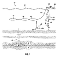
- Fig. 1 depicts an embodiment 10 of a marine seismic data acquisition system in accordance with some embodiments of the invention.
- a survey vessel 20 tows one or more seismic streamers 30 (one exemplary streamer 30 being depicted in Fig. 1 ) behind the vessel 20.
- the seismic streamers 30 may be several thousand meters long and may contain various support cables (not shown), as well as wiring and/or circuitry (not shown) that may be used to support communication along the streamers 30.
- each streamer 30 includes a primary cable into which is mounted seismic sensors 58 that record seismic signals.
- the seismic sensors 58 may be pressure sensors only or may be multi-component seismic sensors.
- each sensor is capable of detecting a pressure wavefield and at least one component of a particle motion that is associated with acoustic signals that are proximate to the multi-component seismic sensor.
- particle motions include one or more components of a particle displacement, one or more components (inline (x), crossline (y) and vertical (z) components (see axes 59, for example)) of a particle velocity and one or more components of a particle acceleration.
- the multi-component seismic sensor may include one or more hydrophones, geophones, particle displacement sensors, particle velocity sensors, accelerometers, pressure gradient sensors, or combinations thereof.
- a particular multi-component seismic sensor may include a hydrophone for measuring pressure and three orthogonally-aligned accelerometers to measure three corresponding orthogonal components of particle velocity and/or acceleration near the seismic sensor. It is noted that the multi-component seismic sensor may be implemented as a single device or may be implemented as a plurality of devices, depending on the particular embodiment of the invention.
- a particular multi-component seismic sensor may also include pressure gradient sensors, which constitute another type of particle motion sensors. Each pressure gradient sensor measures the change in the pressure wavefield at a particular point with respect to a particular direction.
- one of the pressure gradient sensors may acquire seismic data indicative of, at a particular point, the partial derivative of the pressure wavefield with respect to the crossline direction, and another one of the pressure gradient sensors may acquire, a particular point, seismic data indicative of the pressure data with respect to the inline direction.
- the marine seismic data acquisition system 10 includes a seismic source that may be formed from one or more seismic source arrays 102 (one partial source array 102 being depicted in Fig. 1 ). Each source array 102, in turn, includes multiple strings 101 (one string 101 being depicted in Fig. 1 ) of source elements 104 (air guns, for example).
- the seismic source elements 104 may be coupled to, or towed by, the survey vessel 20.
- the seismic source elements 104 may operate independently of the survey vessel 20, in that the elements 104 may be coupled to other vessels or buoys, as just a few examples.
- acoustic signals 42 (an exemplary acoustic signal 42 being depicted in Fig. 1 ), often referred to as "shots," are produced by the seismic source elements 104 and are directed down through a water column 44 into strata 62 and 68 beneath a water bottom surface 24.
- the acoustic signals 42 are reflected from the various subterranean geological formations, such as an exemplary formation 65 that is depicted in Fig. 1 .
- the incident acoustic signals 42 that are acquired by the sources 40 produce corresponding reflected acoustic signals, or pressure waves 60, which are sensed by the seismic sensors 58.
- the pressure waves that are received and sensed by the seismic sensors 58 include "up going” pressure waves that propagate to the sensors 58 without reflection, as well as “down going” pressure waves that are produced by reflections of the pressure waves 60 from an air-water boundary 31.
- the seismic sensors 58 generate signals (digital signals, for example), called “traces," which indicate the acquired measurements of the pressure wavefield and particle motion (if the sensors are particle motion sensors).
- the traces are recorded and may be at least partially processed by a signal processing unit 23 that is deployed on the survey vessel 20, in accordance with some embodiments of the invention.
- a particular multi-component seismic sensor may provide a trace, which corresponds to a measure of a pressure wavefield by its hydrophone; and the sensor may provide one or more traces that correspond to one or more components of particle motion, which are measured by its accelerometers.
- the goal of the seismic acquisition is to build up an image of a survey area for purposes of identifying subterranean geological formations, such as the exemplary geological formation 65.
- Subsequent analysis of the representation may reveal probable locations of hydrocarbon deposits in subterranean geological formations.
- portions of the analysis of the representation may be performed on the seismic survey vessel 20, such as by the signal processing unit 23.
- the representation may be processed by a seismic data processing system (such as an exemplary seismic data processing system 320 that is depicted in Fig. 14 and is further described below) that may be, for example, located on land or on the vessel 20.
- a seismic data processing system such as an exemplary seismic data processing system 320 that is depicted in Fig. 14 and is further described below
- the marine seismic data acquisition system 10 described above is merely an example of one of many different types of seismic data acquisition systems that may be used, in accordance with the many different embodiments of the invention.
- the seismic data acquisition system may use stationary sensor cables that are disposed on the seabed.
- the seismic data acquisition system may be a land-based system in which sensor cables are buried in the earth.
- Seismic migration is a process that is typically is used for purposes of imaging the reflectivity distribution in the earth and involves backprojecting the reflection events that are recorded at the seismic sensors to the corresponding reflection points. Seismic migration may be complicated by seismic anisotropy, which is present in the media of a large number of exploration areas. Therefore, conventional isotropic migration methods for seismic imaging may be generally insufficient in these areas.
- a particular area being surveyed may include vertical transversely isotropic (VTI) media.
- VTI vertical transversely isotropic
- a set of anisotropic wave equations (or "wave propagator") is derived from the dispersion relationship that is set forth in Eq. 1 and may be used to construct the wavefield in the VTI media in a computationally efficient manner, as compared to prior art wave propagators. Forward modeling and migration (reserve-time migration) using this set of anisotropic wave equations are described below.
- Eqs. 5 and 6 are more efficient to implement as less derivatives are calculated.
- another set of wave equations may be derived from Eq. 1 for VTI media, which is computationally more efficient.
- An inverse Fourier transform may then be applied to Eq. 8 using the following relationships: i ⁇ ⁇ ⁇ ⁇ t , - ik x ⁇ ⁇ ⁇ x , - ik y ⁇ ⁇ ⁇ y , - ik z ⁇ ⁇ ⁇ z .
- Eqs. 16 and 17 appear symmetrical, the wavefield function p has a second order derivative in the x and y directions, and the q wavefield function has second order derivatives in the z direction.
- Wavefield functions p and q in Eqs. 16 and 17 have the similar kinematical characteristics, as demonstrated further below.
- the computational cost of the wave equations set forth in Eqs. 5 and 6 may be made comparable to that of Eqs. 16 and 17; but Eqs. 5 and 6 require extra memory to save an intermediate variable (p+q). Characteristics of the p and q functions of all three wave equations are discussed below.
- the p wavefield function expressed in Eqs. 5 and 6 is the same as the q in Eqs. 16 and 17, and the q wavefield function in Eqs. 16 and 17 is equivalent to the sum of p and q in Eqs. 5 and 6.
- Figs. 2 to 6 correspond to the same time snapshot from modeling with the sets of wave equations described herein.
- the ellipsoidal compressional p wavefield and a diamond shape of the SV-wave aliasing wavefield are present in each figure.
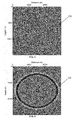
- Fig. 2 illustrates a p wavefield 200 derived using Eqs. 2 and 3.
- the p wavefield 200 and an aliasing SV wavefield 202 are symmetric along the coordinate axes.
- Fig. 3 illustrates a p wavefield 210 and an aliasing SV wavefield 212 derived using Eqs. 5 and 6 with similar wave phenomena. It appears that Eqs. 5 and 6 introduce a directional difference in the wavefront of the SV-wave aliasing. It is clearer to see the problem in Fig. 7 , which displays a difference 250 between the p wavefield 200 ( Fig. 2 ) derived using Eqs. 2 and 3 and the p wavefield 210 ( Fig. 3 ) derived using Eqs. 5 and 6. The difference of the p- wave energy also varies along the wavefront.
- Fig. 4 illustrates a q wavefield 220 derived from Eqs. 5 and 6 is quite similar to the difference 250 that is displayed in Fig. 7 .
- Figs. 5 and 6 depict p 230 and q 240 wavefields derived from Eqs. 16 and 17.
- a p wavefield 230 that is derived from Eqs. 16 and 17 is almost the same as the p wavefield 200 ( Fig. 2 ) that is derived from Eqs. 2 and 3.
- the q wavefield function in Eqs. 16 and 17 is the same as the p wavefield function of Eqs. 5 and 6.
- Fig. 8 shows its impulse response 280 in the same homogeneous anisotropic medium.
- An anisotropic salt model was chosen for purposes of example to verify this operator for complex media.
- Figs. 9 , 10 and 11 correspond to velocity files 290 and anisotropic parameters ( ⁇ 294 and ⁇ 298).
- Fig. 12 displays the anisotropic reverse-time migration result 300.
- a technique 400 in accordance with embodiments of the invention includes obtaining (block 404) seismic measurements of VTI media.
- a wavefield in the VTI media is then modeled, pursuant to block 408, using Eqs. 16 and 17.
- the seismic measurements may then be processed in accordance with the modeled wavefield, pursuant to block 412, for such purposes as migration (as a non-limiting example).
- a data processing system 320 may perform at least some of the techniques that are disclosed herein for such purposes modeling a wavefield in VTI media and processing seismic data indicative of seismic measurements acquired of the VTI media for such purposes of migration (as a non-limiting example).
- the system 320 may be located on one of the streamers, on a source array, on the survey vessel, at a remote land-based facility, on a land-based or seabed based sensor cable, etc.
- the system 320 may include a processor 350, such as one or more microprocessors and/or microcontrollers.
- the processor 350 may be coupled to a communication interface 360 for purposes of receiving seismic measurement data.
- the data may be pressure data and/or may be multi-component data.
- the seismic measurement data may be received from a towed survey, a seabed survey, a land-based survey, etc.
- the interface 360 may be a USB serial bus interface, a network interface, a removable media (such as a flash card, CD-ROM, etc.) interface or a magnetic storage interface (IDE or SCSI interfaces, as examples).
- the interface 360 may take on numerous forms, depending on the particular embodiment of the invention.
- the interface 360 may be coupled to a memory 340 of the system 320 and may store, for example, various input and/or output data sets involved with the techniques that are described herein.
- the memory 340 may store program instructions 344, which when executed by the processor 350, may cause the processor 350 to perform one or more of the techniques that are disclosed herein, such as the technique 400 (as a non-limiting example) and display results obtained via the technique(s) on a display (not shown in Fig. 14 ) of the system 320, in accordance with some embodiments of the invention.
- the display may be an image that depicts reflectivity boundaries that are obtained via a migration analysis.
- the transversely isotropic media may have an axis of symmetry, which is tilted with respect to the vertical, or z, axis.
- a wavefield propagator may be constructed for this tilted transversely isotropic (TTI) media.
- TTI pseudo-acoustic tilted transversely isotropic
- P-SV pressure-vertical shear velocity
- a finite shear velocity is chosen to stabilize these numerical implementations that describe wave propagation in heterogeneous TTI media while minimizing SV waves that are considered as artifacts for acoustic modeling and migration.
- a technique 500 that is depicted in Fig. 16 may be used for TTI media.
- the technique 500 includes modeling (block 504) a seismic wavefield in TTI media, which has a symmetry axis that is tilted relative to a vertical axis based at least in part on an orientation of the symmetry axis and a nonzero shear velocity for the media.
- the technique 500 includes processing the seismic measurements of the media in accordance with the modeled wavefield, pursuant to block 508.
- a wavefield propagator for the TTI media may be constructed as follows.
- the rotation is represented by a dip angle (called “ ⁇ ” herein) measured relative to vertical and an azimuth angle (called “ ⁇ ” herein).
- ⁇ represents angular frequency
- v pz represents the qP wave velocity in the direction normal to the symmetry plane
- v sz represents the qSV velocity normal to the symmetry plane
- ⁇ " and “ ⁇ ” are anisotropic parameters that are defined in Thomsen, L., Weak Elastic Anisotropy, Geophysics, 51, 1954-1996 (1986 ).
- H 1 sin 2 ⁇ ⁇ ⁇ cos 2 ⁇ ⁇ ⁇ ⁇ 2 ⁇ x 2 + sin 2 ⁇ ⁇ ⁇ sin 2 ⁇ ⁇ ⁇ ⁇ 2 ⁇ y 2 + cos 2 ⁇ ⁇ ⁇ ⁇ 2 ⁇ z 2 + sin 2 ⁇ ⁇ ⁇ sin 2 ⁇ ⁇ ⁇ ⁇ 2 ⁇ x ⁇ y + sin 2 ⁇ ⁇ sin ⁇ + ⁇ 2 ⁇ y ⁇ z + sin 2 ⁇ ⁇ cos ⁇ ⁇ ⁇ 2 ⁇ x ⁇ z
- H 2 ⁇ 2 ⁇ x 2 + ⁇ 2 ⁇ y 2 + ⁇ 2 ⁇ z 2 - H 1 .
- a technique 520 that is depicted in Fig. 17 may be used in accordance with embodiments of the invention for purposes of processing seismic measurements obtained from TTI media.
- seismic measurements of TTI media are obtained, pursuant to block 524.
- a wavefield is then modelled, pursuant to Eqs. 32 and 33, pursuant to block 528.
- the seismic measurements are processed (block 532) in accordance with the modelled wavefield.
- a "pseudo-acoustic" wave equation may be derived, based on Eqs. 32 and 33 by setting the vertical shear velocity v sz along the symmetry axis to zero. From the stability criteria that is set forth in Eqs. 34 and 35, when the vertical shear velocity v sz is set to equal zero, the condition reduces to ⁇ - ⁇ 0.
- the instabilities are due to the interaction of the SV artifact with rapid variations in the tilt axis.
- the following analysis and discussion details an approach of using a reasonable finite shear velocity in Eqs. 32 and 33 to remove triplications from the SV wavefront and stabilize wave propagation.
- the exemplary implementation set forth below is based on Eqs. 32 and 33 and uses ordinary centered finite differences.
- Figs. 18 and 19 correspond to the same time snapshot from 2-D modeling with each wave equation: Fig. 18 depicts a snapshot 600 that corresponds to a vertical axis of symmetry; and Fig. 19 depicts a snapshot 610 that corresponds to an axis of symmetry tilting at 45 °.
- the ellipsoidal compressional P-wave wavefront and a diamond shape of the SV-wave aliasing wavefront are depicted in these figures.
- Reverse-time migration was implemented with Eqs. 32 and 33.
- a snapshot 620 in Fig. 20 depicts its impulse response in the same homogeneous anisotropic medium with a 45 ° tilting symmetry axis. In these experiments with a constant tilt axis, the wave propagation is stable.
- ⁇ v pz 2 v sz 2 ⁇ ⁇ - ⁇ .
- Fig. 21 is an illustration 630 of P and SV wavefronts in a strongly anisotropic homogeneous medium for various values of ⁇ .
- triplications in the SV wavefront are removed for values of ⁇ less than 0.8. It has been discovered that stability in the numerically-derived wavefield may be achieved by choosing the vertical shear velocity v sz large enough to ensure ⁇ is small enough to remove SV wavefront triplications, even with a highly heterogeneous tilt axis fields.
- the reflection coefficient of SV-waves at a small-contrast interface between two weakly anisotropic TI media may be expressed as the sum of the corresponding coefficient in isotropic media R isot ( ⁇ ) and the anisotropic term: R aniso , SV ⁇ ⁇ 1 2 ⁇ ⁇ 1 - ⁇ 2 ⁇ sin 2 ⁇ ⁇ , where " ⁇ 1 " and " ⁇ 2 " are the parameters defined in Eq. 36 for above and below the reflector. If the vertical shear velocity v sz is chosen to ensure a constant value of ⁇ for the TTI wave propagator, then this anisotropic term for the SV reflection coefficient is zero.
- a further aspect of the invention provides a method comprising: modeling a seismic wavefield in a vertical transversely isotropic media as a second order derivative of a first wavefield function with respect to a vertical direction and not with respect to crossline and inline direction and as second order derivatives of a second wavefield function with respect to the inline and crossline directions and not with respect to the vertical direction; and processing seismic measurements of the media in accordance with the modeled seismic wavefield to obtain information about the media.
- the processing may comprise performing migration to image a reflectivity distribution associated with the media.
- the modeling may comprise: equating a second order derivative of the first wavefield function with respect to time to a summation of a.) a product of the square of a normal moveout velocity and the second order derivatives of the second wavefield function and b.) a product of the square of a vertical velocity and the second order derivative of the first wavefield function.
- the modeling may comprise: equating a second order derivative of the second wavefield function with respect to time to a summation of a.) a product of the square of a horizontal velocity and the second order derivatives of the second wavefield function and b.) a product of the square of a vertical velocity and the second order derivative of the first wavefield function.
- the processing may performing a reverse time migration.
- a further aspect of the invention provides an article comprising a computer accessible storage medium to store instructions that when executed by a processor-based system cause the system to: model a seismic wavefield in a vertical transversely isotropic media as a second order derivative of a first wavefield function with respect to a vertical direction and not with respect to crossline and inline direction and as second order derivatives of a second wavefield function with respect to the inline and crossline directions and not with respect to the vertical direction; and process seismic measurements of the media in accordance with the modeled seismic wavefield to obtain information about the media.
- the storage medium may store instructions that when executed cause the processor to perform migration to image a reflectivity distribution associated with the media.
- the storage medium may store instructions that when executed cause the processor to: equate a second order derivative of the first wavefield function with respect to time to a summation of a.) a product of the square of a normal moveout velocity and the second order derivatives of the second wavefield function and b.) a product of the square of a vertical velocity and the second order derivative of the first wavefield function.
- the storage medium may store instructions that when executed cause the processor to: equating a second order derivative of the second wavefield function with respect to time to a summation of a.) a product of the square of a horizontal velocity and the second order derivatives of the second wavefield function and b.) a product of the square of a vertical velocity and the second order derivative of the first wavefield function.
- the storage medium may store instructions that when executed cause the processor to perform a reverse time migration.
- a further aspect of the invention provides a system comprising: an interface to receive seismic measurements of a vertical transversely isotropic media; and a processor to: model a seismic wavefield in the media as a second order derivative of a first wavefield function with respect to a vertical direction and not with respect to crossline and inline direction and as second order derivatives of a second wavefield function with respect to the inline and crossline directions and not with respect to the vertical direction; and process the seismic measurements in accordance with the modeled seismic wavefield to obtain information about the media.
- the processor may perform migration to image a reflectivity distribution associated with the media.
- the processor may equate a second order derivative of the first wavefield function with respect to time to a summation of a.) a product of the square of a normal moveout velocity and the second order derivatives of the second wavefield function and b.) a product of the square of a vertical velocity and the second order derivative of the first wavefield function.
- the processor may equate a second order derivative of the second wavefield function with respect to time to a summation of a.) a product of the square of a horizontal velocity and the second order derivatives of the second wavefield function and b.) a product of the square of a vertical velocity and the second order derivative of the first wavefield function.
- the processor may perform a reverse time migration.
- a further aspect of the invention provides a system comprising: an interface to receive seismic measurements of a transversely isotropic media having a symmetry axis that is tilted relative to a vertical axis; and a processor to: model a seismic wavefield in the media based at least in part on an orientation of the symmetry axis and a nonzero shear velocity for the media; and process the seismic measurements of the media in accordance with the modeled seismic wavefield to obtain information associated with the media.
- the processing may comprise performing migration.
- the processing may comprise performing forward modeling.
- the system may further comprise: controlling the modeling to regulate a stability of propagation described by the modeling.
- the act of controlling may comprise removing vertical shear wave mode wavefront triplications.
- the act of controlling may comprise regulating a shear velocity.
Landscapes
- Engineering & Computer Science (AREA)
- Remote Sensing (AREA)
- Physics & Mathematics (AREA)
- Life Sciences & Earth Sciences (AREA)
- Acoustics & Sound (AREA)
- Environmental & Geological Engineering (AREA)
- Geology (AREA)
- General Life Sciences & Earth Sciences (AREA)
- General Physics & Mathematics (AREA)
- Geophysics (AREA)
- Geophysics And Detection Of Objects (AREA)
Abstract
Description
- This application claims the benefit under 35 U.S.C. § 119(e) to
U.S. Provisional Patent Application Serial No. 61/011,606 U.S. Provisional Patent Application Serial No. 61/011,627 U.S. Provisional Patent Application Serial No. 61/104,579 - The invention generally relates to using a wave propagator for transversely isotropic media, and more specifically, the invention relates to using a pseudo-acoustic wave propagator for vertical transversely isotropic media and tilted transversely isotropic media.
- Seismic exploration involves surveying subterranean geological formations for hydrocarbon deposits. A survey typically involves deploying seismic source(s) and seismic sensors at predetermined locations. The sources generate seismic waves, which propagate into the geological formations creating pressure changes and vibrations along their way. Changes in elastic properties of the geological formation scatter the seismic waves, changing their direction of propagation and other properties. Part of the energy emitted by the sources reaches the seismic sensors. Some seismic sensors are sensitive to pressure changes (hydrophones), others to particle motion (e.g., geophones), and industrial surveys may deploy only one type of sensors or both. In response to the detected seismic events, the sensors generate electrical signals to produce seismic data. Analysis of the seismic data can then indicate the presence or absence of probable locations of hydrocarbon deposits.
- Some surveys are known as "marine" surveys because they are conducted in marine environments. However, "marine" surveys may be conducted not only in saltwater environments, but also in fresh and brackish waters. In one type of marine survey, called a "towed-array" survey, an array of seismic sensor-containing streamers and sources is towed behind a survey vessel.
- In an embodiment of the invention, a technique includes modeling a seismic wavefield in a vertical transversely isotropic media as a second order derivative of a first wavefield function with respect to a vertical direction and not with respect to crossline and inline directions and as second order derivatives of a second wavefield function with respect to the inline and crossline directions and not with respect to the vertical direction. The method includes processing seismic measurements of the media in accordance with the modeled seismic wavefield to obtain information about the media.
- In another embodiment of the invention, a technique includes modeling a seismic wavefield in a transversely isotropic media having a symmetry axis that is tilted relative to a vertical axis based at least in part on an orientation of the symmetry axis and a nonzero shear velocity for the media. The technique includes processing seismic measurements of the media in accordance with the modeled seismic wavefield to obtain information, which is associated with the media.
- Advantages and other features of the invention will become apparent from the following drawing, description and claims.
-
-
Fig. 1 is a schematic diagram of a marine seismic data acquisition system according to an embodiment of the invention. -
Figs. 2, 3 and4 are illustrations of wavefields derived from pseudo-acoustic wave propagators for vertical transversely isotropic media of the prior art. -
Fig. 5 and6 are illustrations of wavefields derived from a pseudo-acoustic wave propagator for vertical transversely isotropic media according to an embodiment of the invention. -
Fig. 7 is an illustration of a difference between wavefields derived from wave propagators of the prior art. -
Fig. 8 is an illustration of an impulse response of a wavefield derived from a wave propagator according to an embodiment of the invention. -
Fig. 9 is an illustration of a velocity model according to an embodiment of the invention. -
Figs. 10 and 11 are illustrations of anisotropic parameters according to an embodiment of the invention. -
Fig. 12 depicts the result of prestack anisotropic reverse-time migration according to an embodiment of the invention. -
Fig. 13 is an illustration of an overlap of the anisotropic reverse-time migration ofFig. 12 and the velocity model ofFig. 9 according to an embodiment of the invention. -
Fig. 14 is a schematic diagram of a seismic data processing system according to an embodiment of the invention. -
Fig. 15 is a flow diagram depicting a technique to process seismic data measurements acquired from vertical transversely isotropic media according to an embodiment of the invention. -
Figs. 16 and17 are flow diagrams depicting techniques to process seismic data measurements acquired from tilted transversely isotropic media according to embodiments of the invention. -
Fig. 18 illustrates a synthetic wavefield with a vertical axis of symmetry. -
Fig. 19 illustrates a synthetic wavefield having a tilted axis of symmetry according to an embodiment of the invention. -
Fig. 20 illustrates an impulse response according to an embodiment of the invention. -
Fig. 1 depicts anembodiment 10 of a marine seismic data acquisition system in accordance with some embodiments of the invention. In thesystem 10, asurvey vessel 20 tows one or more seismic streamers 30 (oneexemplary streamer 30 being depicted inFig. 1 ) behind thevessel 20. Theseismic streamers 30 may be several thousand meters long and may contain various support cables (not shown), as well as wiring and/or circuitry (not shown) that may be used to support communication along thestreamers 30. In general, eachstreamer 30 includes a primary cable into which is mountedseismic sensors 58 that record seismic signals. - In accordance with embodiments of the invention, the
seismic sensors 58 may be pressure sensors only or may be multi-component seismic sensors. For the case of multi-component seismic sensors, each sensor is capable of detecting a pressure wavefield and at least one component of a particle motion that is associated with acoustic signals that are proximate to the multi-component seismic sensor. Examples of particle motions include one or more components of a particle displacement, one or more components (inline (x), crossline (y) and vertical (z) components (seeaxes 59, for example)) of a particle velocity and one or more components of a particle acceleration. - Depending on the particular embodiment of the invention, the multi-component seismic sensor may include one or more hydrophones, geophones, particle displacement sensors, particle velocity sensors, accelerometers, pressure gradient sensors, or combinations thereof.
- For example, in accordance with some embodiments of the invention, a particular multi-component seismic sensor may include a hydrophone for measuring pressure and three orthogonally-aligned accelerometers to measure three corresponding orthogonal components of particle velocity and/or acceleration near the seismic sensor. It is noted that the multi-component seismic sensor may be implemented as a single device or may be implemented as a plurality of devices, depending on the particular embodiment of the invention. A particular multi-component seismic sensor may also include pressure gradient sensors, which constitute another type of particle motion sensors. Each pressure gradient sensor measures the change in the pressure wavefield at a particular point with respect to a particular direction. For example, one of the pressure gradient sensors may acquire seismic data indicative of, at a particular point, the partial derivative of the pressure wavefield with respect to the crossline direction, and another one of the pressure gradient sensors may acquire, a particular point, seismic data indicative of the pressure data with respect to the inline direction.
- The marine seismic
data acquisition system 10 includes a seismic source that may be formed from one or more seismic source arrays 102 (onepartial source array 102 being depicted inFig. 1 ). Eachsource array 102, in turn, includes multiple strings 101 (onestring 101 being depicted inFig. 1 ) of source elements 104 (air guns, for example). In some embodiments of the invention, theseismic source elements 104 may be coupled to, or towed by, thesurvey vessel 20. Alternatively, in other embodiments of the invention, theseismic source elements 104 may operate independently of thesurvey vessel 20, in that theelements 104 may be coupled to other vessels or buoys, as just a few examples. - As the
seismic streamers 30 are towed behind thesurvey vessel 20, acoustic signals 42 (an exemplaryacoustic signal 42 being depicted inFig. 1 ), often referred to as "shots," are produced by theseismic source elements 104 and are directed down through awater column 44 intostrata water bottom surface 24. Theacoustic signals 42 are reflected from the various subterranean geological formations, such as anexemplary formation 65 that is depicted inFig. 1 . - The incident
acoustic signals 42 that are acquired by the sources 40 produce corresponding reflected acoustic signals, orpressure waves 60, which are sensed by theseismic sensors 58. It is noted that the pressure waves that are received and sensed by theseismic sensors 58 include "up going" pressure waves that propagate to thesensors 58 without reflection, as well as "down going" pressure waves that are produced by reflections of thepressure waves 60 from an air-water boundary 31. - The
seismic sensors 58 generate signals (digital signals, for example), called "traces," which indicate the acquired measurements of the pressure wavefield and particle motion (if the sensors are particle motion sensors). The traces are recorded and may be at least partially processed by asignal processing unit 23 that is deployed on thesurvey vessel 20, in accordance with some embodiments of the invention. For example, a particular multi-component seismic sensor may provide a trace, which corresponds to a measure of a pressure wavefield by its hydrophone; and the sensor may provide one or more traces that correspond to one or more components of particle motion, which are measured by its accelerometers. - The goal of the seismic acquisition is to build up an image of a survey area for purposes of identifying subterranean geological formations, such as the exemplary
geological formation 65. Subsequent analysis of the representation may reveal probable locations of hydrocarbon deposits in subterranean geological formations. Depending on the particular embodiment of the invention, portions of the analysis of the representation may be performed on theseismic survey vessel 20, such as by thesignal processing unit 23. In accordance with other embodiments of the invention, the representation may be processed by a seismic data processing system (such as an exemplary seismicdata processing system 320 that is depicted inFig. 14 and is further described below) that may be, for example, located on land or on thevessel 20. Thus, many variations are possible and are within the scope of the appended claims. - It is noted that the marine seismic
data acquisition system 10 described above is merely an example of one of many different types of seismic data acquisition systems that may be used, in accordance with the many different embodiments of the invention. For example, in other embodiments of the invention, the seismic data acquisition system may use stationary sensor cables that are disposed on the seabed. As another example, in other embodiments of the invention, the seismic data acquisition system may be a land-based system in which sensor cables are buried in the earth. Thus, many variations are contemplated and are within the scope of the appended claims. - Seismic migration is a process that is typically is used for purposes of imaging the reflectivity distribution in the earth and involves backprojecting the reflection events that are recorded at the seismic sensors to the corresponding reflection points. Seismic migration may be complicated by seismic anisotropy, which is present in the media of a large number of exploration areas. Therefore, conventional isotropic migration methods for seismic imaging may be generally insufficient in these areas.
- As a more specific example, a particular area being surveyed may include vertical transversely isotropic (VTI) media. Starting from the phase velocity equation in VTI media and setting the shear velocity along the symmetry axis to be zero, a dispersion relationship for three-dimensional (3-D) pseudo-acoustic VTI media may be described as follows:

where " kx ", " ky " and " kz " represent wavenumbers in the x , y and z directions, respectively (seeaxes 59 inFig. 1 ); "ω" represents the angular frequency; "vz " represents the vertical velocity;

- As described herein, a set of anisotropic wave equations (or "wave propagator") is derived from the dispersion relationship that is set forth in Eq. 1 and may be used to construct the wavefield in the VTI media in a computationally efficient manner, as compared to prior art wave propagators. Forward modeling and migration (reserve-time migration) using this set of anisotropic wave equations are described below.
- If inverse Fourier transforms are applied, the following conventional set of wave equations, which include the wavefield function " p(x, y, z, t) " and an auxiliary function called " q(x, y, z, t)" may be derived, as described below:


- Another conventional set of wave equations may be derived from Eq. 1 as follows. Eq. 1 may also be reformulated as follows:

- By applying inverse Fourier transforms to Eq. 4 and introducing an auxiliary function called " q(x, y, z, t) ", the following conventional set of wave equations may be derived:


- Compared with Eqs. 2 and 3, Eqs. 5 and 6 are more efficient to implement as less derivatives are calculated.
- In accordance with embodiments of the invention described herein, another set of wave equations may be derived from Eq. 1 for VTI media, which is computationally more efficient. To derive the new set of equations, both sides of Eq. 1 are multiplied with a wavefield function called " p(ω, kx , ky , kz) " and the resulting equation is rewritten using the following expression:

The resulting equation is the following:
- An inverse Fourier transform may then be applied to Eq. 8 using the following relationships:


- The above-described procedure produces the following equations:


Substituting Eq. 13 into Eq. 14 yields the following expression:
- The final set of wave equations may be written as follows:


- For seismic forward modeling, the source function is injected in the right side of both Eqs. 16 and 17. Eqs. 16 and 17 appear symmetrical, the wavefield function p has a second order derivative in the x and y directions, and the q wavefield function has second order derivatives in the z direction.
- Wavefield functions p and q in Eqs. 16 and 17 have the similar kinematical characteristics, as demonstrated further below. The computational cost of the wave equations set forth in Eqs. 5 and 6 may be made comparable to that of Eqs. 16 and 17; but Eqs. 5 and 6 require extra memory to save an intermediate variable (p+q). Characteristics of the p and q functions of all three wave equations are discussed below.
- It is noted that the set of wave equations that is expressed in Eqs. 5 and 6 with the denotation of variables p' and q' may be derived by assuming " p = p' + q'" and " q = p' " in Eqs. 16 and 17, which produces the following expressions:


By substituting Eq. 19 into Eq. 18, Eq. 18 becomes the following:
- Thus, the p wavefield function expressed in Eqs. 5 and 6 is the same as the q in Eqs. 16 and 17, and the q wavefield function in Eqs. 16 and 17 is equivalent to the sum of p and q in Eqs. 5 and 6.
- In a modeling experiment, time snapshots of wave propagation in a homogenous anisotropic media (vz = 3000 m/s, ε = 0.24, and δ = 0.1) were simulated using finite differencing.
Figs. 2 to 6 correspond to the same time snapshot from modeling with the sets of wave equations described herein. The ellipsoidal compressional p wavefield and a diamond shape of the SV-wave aliasing wavefield are present in each figure. -
Fig. 2 illustrates ap wavefield 200 derived using Eqs. 2 and 3. Thep wavefield 200 and analiasing SV wavefield 202 are symmetric along the coordinate axes.Fig. 3 illustrates ap wavefield 210 and an aliasing SV wavefield 212 derived using Eqs. 5 and 6 with similar wave phenomena. It appears that Eqs. 5 and 6 introduce a directional difference in the wavefront of the SV-wave aliasing. It is clearer to see the problem inFig. 7 , which displays adifference 250 between the p wavefield 200 (Fig. 2 ) derived using Eqs. 2 and 3 and the p wavefield 210 (Fig. 3 ) derived using Eqs. 5 and 6. The difference of the p-wave energy also varies along the wavefront. -
Fig. 4 illustrates aq wavefield 220 derived from Eqs. 5 and 6 is quite similar to thedifference 250 that is displayed inFig. 7 .Figs. 5 and6 depictp 230 andq 240 wavefields derived from Eqs. 16 and 17. Referring toFig. 5 , ap wavefield 230 that is derived from Eqs. 16 and 17 is almost the same as the p wavefield 200 (Fig. 2 ) that is derived from Eqs. 2 and 3. Referring toFig. 6 , the q wavefield function in Eqs. 16 and 17 is the same as the p wavefield function of Eqs. 5 and 6. - Reverse-time migration was implemented using Eqs. 16 and 17.
Fig. 8 shows itsimpulse response 280 in the same homogeneous anisotropic medium. An anisotropic salt model was chosen for purposes of example to verify this operator for complex media.Figs. 9 ,10 and 11 correspond to velocity files 290 and anisotropic parameters (ε 294 and δ 298).Fig. 12 displays the anisotropic reverse-time migration result 300. - The accurate imaging of the steep fault, salt tank and the two abnormal sediments can be seen from an
overlay 312 of the image on the velocity model, which is depicted inFig. 13 . - Referring to
Fig. 15 , to summarize atechnique 400 in accordance with embodiments of the invention includes obtaining (block 404) seismic measurements of VTI media. A wavefield in the VTI media is then modeled, pursuant to block 408, using Eqs. 16 and 17. The seismic measurements may then be processed in accordance with the modeled wavefield, pursuant to block 412, for such purposes as migration (as a non-limiting example). - Referring to
Fig. 14 , in accordance with some embodiments of the invention, adata processing system 320 may perform at least some of the techniques that are disclosed herein for such purposes modeling a wavefield in VTI media and processing seismic data indicative of seismic measurements acquired of the VTI media for such purposes of migration (as a non-limiting example). Thesystem 320 may be located on one of the streamers, on a source array, on the survey vessel, at a remote land-based facility, on a land-based or seabed based sensor cable, etc. In accordance with some embodiments of the invention, thesystem 320 may include aprocessor 350, such as one or more microprocessors and/or microcontrollers. - The
processor 350 may be coupled to acommunication interface 360 for purposes of receiving seismic measurement data. In this regard, the data may be pressure data and/or may be multi-component data. Furthermore, the seismic measurement data may be received from a towed survey, a seabed survey, a land-based survey, etc. As examples, theinterface 360 may be a USB serial bus interface, a network interface, a removable media (such as a flash card, CD-ROM, etc.) interface or a magnetic storage interface (IDE or SCSI interfaces, as examples). Thus, theinterface 360 may take on numerous forms, depending on the particular embodiment of the invention. - In accordance with some embodiments of the invention, the
interface 360 may be coupled to amemory 340 of thesystem 320 and may store, for example, various input and/or output data sets involved with the techniques that are described herein. Thememory 340 may storeprogram instructions 344, which when executed by theprocessor 350, may cause theprocessor 350 to perform one or more of the techniques that are disclosed herein, such as the technique 400 (as a non-limiting example) and display results obtained via the technique(s) on a display (not shown inFig. 14 ) of thesystem 320, in accordance with some embodiments of the invention. For example, the display may be an image that depicts reflectivity boundaries that are obtained via a migration analysis. - Other embodiments are contemplated and are within the scope of the appended claims. For example, in accordance with some embodiments of the invention, the transversely isotropic media may have an axis of symmetry, which is tilted with respect to the vertical, or z, axis. As described herein, a wavefield propagator may be constructed for this tilted transversely isotropic (TTI) media.
- More specifically, the following description focuses on a pseudo-acoustic tilted transversely isotropic (TTI) wave equation derived using a pressure-vertical shear velocity ( P-SV) TTI dispersion relation. For media with a constant vertical axis of symmetry, it is relatively straightforward to implement modeling and migration with the vertical shear velocity set to zero. However, for modeling and migration in heterogeneous TTI media, it has been discovered that a variable non-vertical axis of symmetry may cause instabilities with numerical implementations. As described herein, a finite shear velocity is chosen to stabilize these numerical implementations that describe wave propagation in heterogeneous TTI media while minimizing SV waves that are considered as artifacts for acoustic modeling and migration.
- Thus, in accordance with embodiments of the invention, a
technique 500 that is depicted inFig. 16 may be used for TTI media. Thetechnique 500 includes modeling (block 504) a seismic wavefield in TTI media, which has a symmetry axis that is tilted relative to a vertical axis based at least in part on an orientation of the symmetry axis and a nonzero shear velocity for the media. Thetechnique 500 includes processing the seismic measurements of the media in accordance with the modeled wavefield, pursuant to block 508. - As a non-limiting example, a wavefield propagator for the TTI media may be constructed as follows. The rotation is represented by a dip angle (called "θ" herein) measured relative to vertical and an azimuth angle (called "φ" herein). The rotated wavenumbers may be described in terms of the dip θ and azimuth φ angles as follows:


- The exact P-SV TTI dispersion relation may be written as follows:

where the "^" notation over the wavenumbers indicates that the wavenumbers are evaluated in a rotated coordinate system aligned with the symmetry axis. In Eq. 24, " ω" represents angular frequency; "vpz " represents the qP wave velocity in the direction normal to the symmetry plane;

In view of Eqs. 21-23, Eq. 24 may be rewritten as follows:
where "f1" and "f2" are described as follows:

- By applying an inverse Fourier transformation to Eqs. 26 and 27, the following differential operators may be obtained:


- It is noted, that for VTI, these differential operators do not contain mixed space derivatives. Direct solution of the corresponding fourth-order partial differential equation (PDE) in time, following immediately from Eq. 25, is cumbersome to solve as it is a fourth-order equation in time. Mixed spatial derivatives generally require more computation than derivatives in a single spatial variable because differencing operators become two or three dimensional convolutions rather than one dimensional. For this reason, equivalent coupled lower-order systems are sought.
- Both sides of the dispersion relation of Eq. 25 may be multiplied with the wavefield p(ω, kx, ky, kz) (the pressure wavefield) to derive the following equation:

In Eq. 30, the auxiliary function of q(ω, kx, ky, kz) is defined as follows:
- By applying an inverse Fourier transformation to both sides of Eqs. 30 and 31, the final equations may be written as follows:


- To summarize, a
technique 520 that is depicted inFig. 17 may be used in accordance with embodiments of the invention for purposes of processing seismic measurements obtained from TTI media. Referring toFig. 17 , pursuant to thetechnique 520, seismic measurements of TTI media are obtained, pursuant to block 524. A wavefield is then modelled, pursuant to Eqs. 32 and 33, pursuant to block 528. The seismic measurements are processed (block 532) in accordance with the modelled wavefield. - For seismic forward modeling, the source function is injected in the right side of both Eqs. 32 and 33. Evaluation of the constraint on the stiffness coefficients of TI media gives the following stability condition:

where
- A "pseudo-acoustic" wave equation may be derived, based on Eqs. 32 and 33 by setting the vertical shear velocity vsz along the symmetry axis to zero. From the stability criteria that is set forth in Eqs. 34 and 35, when the vertical shear velocity vsz is set to equal zero, the condition reduces to ε-δ≥0.
- It has been discovered that when the vertical shear velocity vsz is set equal to zero, and certain numerical computation techniques (such as an ordinary centered finite differences technique, for example) are used, an instability is introduced for some media that have inhomogeneous azimuth and dip angles. The instabilities usually start at locations in the azimuth and dip models where sharp contrasts exist.
- The instabilities are due to the interaction of the SV artifact with rapid variations in the tilt axis. The following analysis and discussion details an approach of using a reasonable finite shear velocity in Eqs. 32 and 33 to remove triplications from the SV wavefront and stabilize wave propagation. The exemplary implementation set forth below is based on Eqs. 32 and 33 and uses ordinary centered finite differences.
- In a modeling experiment, time snapshots of wave propagation in a homogenous anisotropic media (vpz = 3000 m/s, vsz = 0 , ε = 0.24 , and δ=0.1) were simulated using finite differencing.
Figs. 18 and 19 correspond to the same time snapshot from 2-D modeling with each wave equation:Fig. 18 depicts asnapshot 600 that corresponds to a vertical axis of symmetry; andFig. 19 depicts asnapshot 610 that corresponds to an axis of symmetry tilting at 45 °. The ellipsoidal compressional P-wave wavefront and a diamond shape of the SV-wave aliasing wavefront are depicted in these figures. - Reverse-time migration (RTM) was implemented with Eqs. 32 and 33. A
snapshot 620 inFig. 20 depicts its impulse response in the same homogeneous anisotropic medium with a 45 ° tilting symmetry axis. In these experiments with a constant tilt axis, the wave propagation is stable. - In a significantly more complex 2-D anisotropic model, it has been discovered that the constructed wave propagation is unstable where a high contrast exists in the dip field. As described below, the constructed wave propagation was stabilized by adding a finite shear velocity.
- The following parameter σ largely determines the kinematic signatures of SV-waves in TI media:

- Fig. 21 is an illustration 630 of P and SV wavefronts in a strongly anisotropic homogeneous medium for various values of σ. As described in Tsvankin, I., Seismic Signatures and Analysis of Reflection Data in Anisotropic Media, Elsevier, 2001, triplications in the SV wavefront are removed for values of σ less than 0.8. It has been discovered that stability in the numerically-derived wavefield may be achieved by choosing the vertical shear velocity vsz large enough to ensure σ is small enough to remove SV wavefront triplications, even with a highly heterogeneous tilt axis fields.
- As described in the Tsvankin article, the reflection coefficient of SV-waves at a small-contrast interface between two weakly anisotropic TI media may be expressed as the sum of the corresponding coefficient in isotropic media Risot (θ) and the anisotropic term:

- While the present invention has been described with respect to a limited number of embodiments, those skilled in the art, having the benefit of this disclosure, will appreciate numerous modifications and variations therefrom. It is intended that the appended claims cover all such modifications and variations as fall within the true spirit and scope of this present invention.
- For example, a further aspect of the invention provides a method comprising: modeling a seismic wavefield in a vertical transversely isotropic media as a second order derivative of a first wavefield function with respect to a vertical direction and not with respect to crossline and inline direction and as second order derivatives of a second wavefield function with respect to the inline and crossline directions and not with respect to the vertical direction; and processing seismic measurements of the media in accordance with the modeled seismic wavefield to obtain information about the media.
- The processing may comprise performing migration to image a reflectivity distribution associated with the media.
- The modeling may comprise: equating a second order derivative of the first wavefield function with respect to time to a summation of a.) a product of the square of a normal moveout velocity and the second order derivatives of the second wavefield function and b.) a product of the square of a vertical velocity and the second order derivative of the first wavefield function.
- The modeling may comprise: equating a second order derivative of the second wavefield function with respect to time to a summation of a.) a product of the square of a horizontal velocity and the second order derivatives of the second wavefield function and b.) a product of the square of a vertical velocity and the second order derivative of the first wavefield function.
- The processing may performing a reverse time migration.
- A further aspect of the invention provides an article comprising a computer accessible storage medium to store instructions that when executed by a processor-based system cause the system to: model a seismic wavefield in a vertical transversely isotropic media as a second order derivative of a first wavefield function with respect to a vertical direction and not with respect to crossline and inline direction and as second order derivatives of a second wavefield function with respect to the inline and crossline directions and not with respect to the vertical direction; and process seismic measurements of the media in accordance with the modeled seismic wavefield to obtain information about the media.
- The storage medium may store instructions that when executed cause the processor to perform migration to image a reflectivity distribution associated with the media.
- The storage medium may store instructions that when executed cause the processor to: equate a second order derivative of the first wavefield function with respect to time to a summation of a.) a product of the square of a normal moveout velocity and the second order derivatives of the second wavefield function and b.) a product of the square of a vertical velocity and the second order derivative of the first wavefield function.
- The storage medium may store instructions that when executed cause the processor to: equating a second order derivative of the second wavefield function with respect to time to a summation of a.) a product of the square of a horizontal velocity and the second order derivatives of the second wavefield function and b.) a product of the square of a vertical velocity and the second order derivative of the first wavefield function.
- The storage medium may store instructions that when executed cause the processor to perform a reverse time migration.
- A further aspect of the invention provides a system comprising: an interface to receive seismic measurements of a vertical transversely isotropic media; and a processor to: model a seismic wavefield in the media as a second order derivative of a first wavefield function with respect to a vertical direction and not with respect to crossline and inline direction and as second order derivatives of a second wavefield function with respect to the inline and crossline directions and not with respect to the vertical direction; and process the seismic measurements in accordance with the modeled seismic wavefield to obtain information about the media.
- The processor may perform migration to image a reflectivity distribution associated with the media.
- The processor may equate a second order derivative of the first wavefield function with respect to time to a summation of a.) a product of the square of a normal moveout velocity and the second order derivatives of the second wavefield function and b.) a product of the square of a vertical velocity and the second order derivative of the first wavefield function.
- The processor may equate a second order derivative of the second wavefield function with respect to time to a summation of a.) a product of the square of a horizontal velocity and the second order derivatives of the second wavefield function and b.) a product of the square of a vertical velocity and the second order derivative of the first wavefield function.
- The processor may perform a reverse time migration.
- A further aspect of the invention provides a system comprising: an interface to receive seismic measurements of a transversely isotropic media having a symmetry axis that is tilted relative to a vertical axis; and a processor to: model a seismic wavefield in the media based at least in part on an orientation of the symmetry axis and a nonzero shear velocity for the media; and process the seismic measurements of the media in accordance with the modeled seismic wavefield to obtain information associated with the media.
- The processing may comprise performing migration.
- The processing may comprise performing forward modeling.
- The system may further comprise: controlling the modeling to regulate a stability of propagation described by the modeling.
- The act of controlling may comprise removing vertical shear wave mode wavefront triplications.
- The act of controlling may comprise regulating a shear velocity.
Claims (10)
- A method comprising:providing seismic measurements of a transversely isotropic medium having a symmetry axis that is tilted relative to a vertical axis;modeling (504) a seismic wavefield in the media based at least in part on orientation of the symmetry axis and a nonzero shear velocity for the medium; andprocessing (508) the seismic measurements of the media in accordance with the modeled seismic wavefield to obtain information associated with the medium.
- The method of claim 1, wherein the processing comprises performing migration.
- The method of claim 1, wherein the processing comprises performing forward modeling.
- The method of claim 1, further comprising:controlling the modeling to regulate a stability of propagation described by the modeling.
- The method of claim 4, wherein the act of controlling comprises removing vertical shear wave mode wavefront triplications.
- The method of claim 4, wherein the act of controlling comprises regulating a shear velocity.
- A system comprising:an interface (360) to receive seismic measurements of a transversely isotropic medium; anda processor (350) to execute instructions to cause the system to perform a method as defined in any one of claims 1-6.
- The system of claim 7, further comprising:a survey vessel (20).
- The system of claim 7, further comprising:a streamer (30) adapted to be towed by the survey vessel,wherein the processor is part of the streamer.
- An article comprising a computer accessible storage medium to store instructions that when executed by a processor-based system cause the system to perform a method as defined in any one of claims 1 to 6.
Applications Claiming Priority (5)
| Application Number | Priority Date | Filing Date | Title |
|---|---|---|---|
| US1160608P | 2008-01-18 | 2008-01-18 | |
| US1162708P | 2008-01-18 | 2008-01-18 | |
| US10457908P | 2008-10-10 | 2008-10-10 | |
| US12/354,346 US8194498B2 (en) | 2008-01-18 | 2009-01-15 | Using a wave propagator for transversely isotropic media |
| EP09702315A EP2238475A2 (en) | 2008-01-18 | 2009-01-16 | Using a wave propagator for transversely isotropic media |
Related Parent Applications (1)
| Application Number | Title | Priority Date | Filing Date |
|---|---|---|---|
| EP09702315A Division EP2238475A2 (en) | 2008-01-18 | 2009-01-16 | Using a wave propagator for transversely isotropic media |
Publications (2)
| Publication Number | Publication Date |
|---|---|
| EP2811321A2 true EP2811321A2 (en) | 2014-12-10 |
| EP2811321A3 EP2811321A3 (en) | 2016-11-02 |
Family
ID=40885901
Family Applications (2)
| Application Number | Title | Priority Date | Filing Date |
|---|---|---|---|
| EP09702315A Withdrawn EP2238475A2 (en) | 2008-01-18 | 2009-01-16 | Using a wave propagator for transversely isotropic media |
| EP14183434.1A Withdrawn EP2811321A3 (en) | 2008-01-18 | 2009-01-16 | Using a wave propagator for transversely isotropic media |
Family Applications Before (1)
| Application Number | Title | Priority Date | Filing Date |
|---|---|---|---|
| EP09702315A Withdrawn EP2238475A2 (en) | 2008-01-18 | 2009-01-16 | Using a wave propagator for transversely isotropic media |
Country Status (4)
| Country | Link |
|---|---|
| US (1) | US8194498B2 (en) |
| EP (2) | EP2238475A2 (en) |
| MX (1) | MX2010007868A (en) |
| WO (1) | WO2009092025A2 (en) |
Cited By (1)
| Publication number | Priority date | Publication date | Assignee | Title |
|---|---|---|---|---|
| WO2018070857A1 (en) * | 2016-10-14 | 2018-04-19 | Pech Perez Andres | Method and system for the detection and characterisation of waves induced by the flow of fluids, atomic particle flows, fracture propagation and geological fault activation |
Families Citing this family (25)
| Publication number | Priority date | Publication date | Assignee | Title |
|---|---|---|---|---|
| US8116168B1 (en) | 2008-06-18 | 2012-02-14 | Halliburton Energy Services, Inc. | Hybrid one-way and full-way wave equation migration |
| US9864082B2 (en) * | 2008-11-06 | 2018-01-09 | Pgs Geophysical As | Fourier finite-difference migration for three dimensional tilted transverse isotropic media |
| AU2009337134B2 (en) | 2009-01-19 | 2013-11-21 | Landmark Graphics Corporation | Data acquisition and prestack migration based on seismic visibility analysis |
| EP2497043B1 (en) * | 2009-11-02 | 2017-10-11 | Landmark Graphics Corporation | Seismic imaging systems and methods employing a 3d reverse time migration with tilted transverse isotropy |
| US8659974B2 (en) | 2010-03-16 | 2014-02-25 | Bp Corporation North America Inc. | System and method of 3D salt flank VSP imaging with transmitted waves |
| GB2492922B (en) * | 2010-05-12 | 2016-01-20 | Shell Int Research | Seismic p-wave modelling in an inhomogeneous transversely isotropic medium with a tilted symmetry axis |
| US20120099396A1 (en) * | 2010-10-22 | 2012-04-26 | Chevron U.S.A. Inc. | System and method for characterization with non-unique solutions of anisotropic velocities |
| US8830788B2 (en) | 2011-02-24 | 2014-09-09 | Landmark Graphics Corporation | Sensitivity kernal-based migration velocity analysis in 3D anisotropic media |
| US10436921B2 (en) | 2011-07-27 | 2019-10-08 | Schlumberger Technology Corporation | Multi-well anisotropy inversion |
| US20130088939A1 (en) * | 2011-10-10 | 2013-04-11 | Pascal Edme | Wavefield separation using a gradient sensor |
| US20130242693A1 (en) * | 2012-03-13 | 2013-09-19 | Seoul National University R&Db Foundation | Seismic imaging system using a reverse time migration algorithm |
| CA2881807C (en) * | 2012-08-17 | 2017-10-17 | Landmark Graphics Corporation | Systems and methods for imaging seismic data |
| US10620330B2 (en) | 2013-03-19 | 2020-04-14 | Westerngeco L.L.C. | Estimating translational data |
| CN104597484A (en) * | 2013-10-31 | 2015-05-06 | 中国石油天然气集团公司 | Three-dimensional transmission time interval (TTI) earthquake anisotropic medium reverse time migration imaging method and device |
| US20150185346A1 (en) * | 2013-12-30 | 2015-07-02 | Chevron U.S.A. Inc. | System and method of mitigating instabilities in a pseudoacoustic wave propagator |
| MA40449A (en) * | 2014-07-17 | 2017-05-24 | Conocophillips Co | Controlled spaced streamer acquisition |
| US10605941B2 (en) | 2014-12-18 | 2020-03-31 | Conocophillips Company | Methods for simultaneous source separation |
| US10215869B2 (en) * | 2015-03-30 | 2019-02-26 | Chevron U.S.A. Inc. | System and method of estimating anisotropy properties of geological formations using a self-adjoint pseudoacoustic wave propagator |
| CA2999920A1 (en) | 2015-09-28 | 2017-04-06 | Conocophillips Company | 3d seismic acquisition |
| CN105717539B (en) * | 2016-01-28 | 2018-01-30 | 中国地质大学(北京) | A kind of three-dimensional TTI media reverse-time migration imaging method calculated based on more GPU |
| US10809402B2 (en) | 2017-05-16 | 2020-10-20 | Conocophillips Company | Non-uniform optimal survey design principles |
| WO2019013906A1 (en) * | 2017-07-13 | 2019-01-17 | Exxonmobil Upstream Research Company | Visco-pseudo-elastic tti fwi/rtm formulation and implementation |
| WO2019100068A1 (en) | 2017-11-20 | 2019-05-23 | Conocophillips Company | Offshore application of non-uniform optimal sampling survey design |
| US11481677B2 (en) | 2018-09-30 | 2022-10-25 | Shearwater Geoservices Software Inc. | Machine learning based signal recovery |
| CN116736392A (en) * | 2023-05-09 | 2023-09-12 | 中国石油大学(北京) | Formation data processing methods, devices and electronic equipment |
Family Cites Families (5)
| Publication number | Priority date | Publication date | Assignee | Title |
|---|---|---|---|---|
| US6317695B1 (en) | 2000-03-30 | 2001-11-13 | Nutec Sciences, Inc. | Seismic data processing method |
| US6748330B2 (en) * | 2002-04-10 | 2004-06-08 | Schlumberger Technology Corporation | Method and apparatus for anisotropic vector plane wave decomposition for 3D vertical seismic profile data |
| US6819628B2 (en) | 2003-04-07 | 2004-11-16 | Paradigm Geophysical (Luxembourg) S.A.R.L. | Wave migration by a krylov space expansion of the square root exponent operator, for use in seismic imaging |
| FR2858063B1 (en) * | 2003-07-21 | 2005-09-16 | Geophysique Cie Gle | METHOD FOR ESTIMATING THE ILLUMINATION COVERAGE RATE IN THE MIGRE DOMAIN |
| US20070162249A1 (en) * | 2006-01-06 | 2007-07-12 | Min Lou | Traveltime calculation in three dimensional transversely isotropic (3D TTI) media by the fast marching method |
-
2009
- 2009-01-15 US US12/354,346 patent/US8194498B2/en not_active Expired - Fee Related
- 2009-01-16 MX MX2010007868A patent/MX2010007868A/en active IP Right Grant
- 2009-01-16 EP EP09702315A patent/EP2238475A2/en not_active Withdrawn
- 2009-01-16 EP EP14183434.1A patent/EP2811321A3/en not_active Withdrawn
- 2009-01-16 WO PCT/US2009/031315 patent/WO2009092025A2/en not_active Ceased
Non-Patent Citations (2)
| Title |
|---|
| THOMSEN, L.: "Weak Elastic Anisotropy", GEOPHYSICS, vol. 51, 1986, pages 1954 - 1996 |
| TSVANKIN, I.: "Seismic Signatures and Analysis of Reflection Data in Anisotropic Media", 2001, ELSEVIER |
Cited By (1)
| Publication number | Priority date | Publication date | Assignee | Title |
|---|---|---|---|---|
| WO2018070857A1 (en) * | 2016-10-14 | 2018-04-19 | Pech Perez Andres | Method and system for the detection and characterisation of waves induced by the flow of fluids, atomic particle flows, fracture propagation and geological fault activation |
Also Published As
| Publication number | Publication date |
|---|---|
| US8194498B2 (en) | 2012-06-05 |
| WO2009092025A9 (en) | 2009-12-17 |
| MX2010007868A (en) | 2010-08-09 |
| EP2811321A3 (en) | 2016-11-02 |
| WO2009092025A2 (en) | 2009-07-23 |
| US20090213693A1 (en) | 2009-08-27 |
| WO2009092025A3 (en) | 2011-02-10 |
| EP2238475A2 (en) | 2010-10-13 |
Similar Documents
| Publication | Publication Date | Title |
|---|---|---|
| US8194498B2 (en) | Using a wave propagator for transversely isotropic media | |
| EP2283385B1 (en) | Jointly interpolating and deghosting seismic data | |
| EP4042210B1 (en) | Determining properties of a subterranean formation using an acoustic wave equation with a reflectivity parameterization | |
| US7715988B2 (en) | Interpolating and deghosting multi-component seismic sensor data | |
| US10162073B2 (en) | Marine surveys conducted with multiple source arrays | |
| US10989825B2 (en) | Method and system for determining source signatures after source ghost removal | |
| US8937848B2 (en) | Methods and systems to eliminate undesirable variations in time-lapse seismic surveys | |
| US20100142316A1 (en) | Using waveform inversion to determine properties of a subsurface medium | |
| US20100211320A1 (en) | Reconstructing a seismic wavefield | |
| US20060250890A1 (en) | Method for deghosting and water layer multiple reflection attenuation in marine seismic data | |
| EP2279436B1 (en) | System and technique to determine high order derivatives from seismic sensor data | |
| US20100211322A1 (en) | Interpolating a pressure wavefield along an undersampled direction | |
| EP3956696B1 (en) | Attenuation of low-frequency noise in continously recorded wavefields | |
| US11709288B2 (en) | Seismic imaging with source deconvolution for marine vibrators with random source signatures | |
| AU2021205226A1 (en) | Systems and methods for performing seismic survey in shallow water areas | |
| US9046626B2 (en) | Performing reverse time imaging of multicomponent acoustic and seismic data | |
| Zhu et al. | Recent advances in multicomponent processing | |
| US20220299666A1 (en) | Deconvolution of down-going seismic wavefields |
Legal Events
| Date | Code | Title | Description |
|---|---|---|---|
| PUAI | Public reference made under article 153(3) epc to a published international application that has entered the european phase |
Free format text: ORIGINAL CODE: 0009012 |
|
| 17P | Request for examination filed |
Effective date: 20140903 |
|
| AC | Divisional application: reference to earlier application |
Ref document number: 2238475 Country of ref document: EP Kind code of ref document: P |
|
| AK | Designated contracting states |
Kind code of ref document: A2 Designated state(s): AT BE BG CH CY CZ DE DK EE ES FI FR GB GR HR HU IE IS IT LI LT LU LV MC MK MT NL NO PL PT RO SE SI SK TR |
|
| PUAL | Search report despatched |
Free format text: ORIGINAL CODE: 0009013 |
|
| RIC1 | Information provided on ipc code assigned before grant |
Ipc: G01V 1/28 20060101AFI20160915BHEP |
|
| AK | Designated contracting states |
Kind code of ref document: A3 Designated state(s): AT BE BG CH CY CZ DE DK EE ES FI FR GB GR HR HU IE IS IT LI LT LU LV MC MK MT NL NO PL PT RO SE SI SK TR |
|
| STAA | Information on the status of an ep patent application or granted ep patent |
Free format text: STATUS: REQUEST FOR EXAMINATION WAS MADE |
|
| STAA | Information on the status of an ep patent application or granted ep patent |
Free format text: STATUS: THE APPLICATION IS DEEMED TO BE WITHDRAWN |
|
| 18D | Application deemed to be withdrawn |
Effective date: 20170503 |