EP2811231A1 - Cooker - Google Patents
Cooker Download PDFInfo
- Publication number
- EP2811231A1 EP2811231A1 EP13743452.8A EP13743452A EP2811231A1 EP 2811231 A1 EP2811231 A1 EP 2811231A1 EP 13743452 A EP13743452 A EP 13743452A EP 2811231 A1 EP2811231 A1 EP 2811231A1
- Authority
- EP
- European Patent Office
- Prior art keywords
- tray
- heating cabinet
- stoppers
- cooker
- contact
- Prior art date
- Legal status (The legal status is an assumption and is not a legal conclusion. Google has not performed a legal analysis and makes no representation as to the accuracy of the status listed.)
- Withdrawn
Links
- 238000010438 heat treatment Methods 0.000 claims abstract description 210
- 238000000034 method Methods 0.000 claims abstract description 11
- 230000002093 peripheral effect Effects 0.000 claims description 7
- 239000011521 glass Substances 0.000 description 97
- 239000002184 metal Substances 0.000 description 83
- 229910052751 metal Inorganic materials 0.000 description 83
- 238000001816 cooling Methods 0.000 description 8
- 230000000694 effects Effects 0.000 description 8
- XLYOFNOQVPJJNP-UHFFFAOYSA-N water Substances O XLYOFNOQVPJJNP-UHFFFAOYSA-N 0.000 description 5
- 238000004519 manufacturing process Methods 0.000 description 4
- 238000010411 cooking Methods 0.000 description 3
- 230000002401 inhibitory effect Effects 0.000 description 3
- 238000000465 moulding Methods 0.000 description 3
- 238000000638 solvent extraction Methods 0.000 description 3
- XEEYBQQBJWHFJM-UHFFFAOYSA-N Iron Chemical compound [Fe] XEEYBQQBJWHFJM-UHFFFAOYSA-N 0.000 description 2
- 230000000593 degrading effect Effects 0.000 description 2
- 238000009434 installation Methods 0.000 description 2
- 239000007788 liquid Substances 0.000 description 2
- 239000000463 material Substances 0.000 description 2
- 210000001364 upper extremity Anatomy 0.000 description 2
- 229920006015 heat resistant resin Polymers 0.000 description 1
- 238000003780 insertion Methods 0.000 description 1
- 230000037431 insertion Effects 0.000 description 1
- 239000011810 insulating material Substances 0.000 description 1
- 229910052742 iron Inorganic materials 0.000 description 1
- 239000004973 liquid crystal related substance Substances 0.000 description 1
- 238000010025 steaming Methods 0.000 description 1
Images











Classifications
-
- F—MECHANICAL ENGINEERING; LIGHTING; HEATING; WEAPONS; BLASTING
- F24—HEATING; RANGES; VENTILATING
- F24C—DOMESTIC STOVES OR RANGES ; DETAILS OF DOMESTIC STOVES OR RANGES, OF GENERAL APPLICATION
- F24C15/00—Details
- F24C15/16—Shelves, racks or trays inside ovens; Supports therefor
Definitions
- the present invention relates to a cooker.
- a cooker which includes a heating cabinet having an opening on its front side, a tray to be removably placed in the heating cabinet for mounting thereon a heating object, which is to be heated, and tray holders provided on individual side faces of the heating cabinet to hold the tray from below (see, e.g., JP 2011-163697 A (PTL1)).
- the tray holders extending from proximities of the opening on the front side of the heating cabinet to proximities of a rear-end wall of the heating cabinet, serve also for guiding the tray into the heating cabinet when the tray is put into the heating cabinet.
- an object of the present invention is to provide a cooker capable of preventing the tray and heating objects from falling off.
- a cooker according to the present invention comprises a casing; a heating cabinet provided in the casing and having an opening on its front side; a door for opening and closing the opening (8a) of the heating cabinet; a tray to be removably placed in the heating cabinet for mounting thereon a heating object, which is to be heated; holding parts provided on an inner surface of the heating cabinet and serving for holding the tray in the heating cabinet; and restricting parts provided on the inner surface of the heating cabinet and serving for, when put into contact with part of the tray, restricting forward moves of the tray, wherein in process of pulling out the tray from within the heating cabinet, the tray is tilted in a direction other than a forward direction in a state that the restricting parts are in contact with the part of the tray, whereby the contact of the restricting parts with the part of the tray is released, thus allowing the tray to be pulled out of the heating cabinet.
- the restricting parts make contact with the part of the tray, by which forward moves of the tray are restricted. Accordingly, even if the front sides of the holding parts are hidden invisible by the tray, the tray and the heating object can be prevented from falling off due to the user's erroneous, excessive pull-out of the tray.
- the tray in process of pulling out the tray from within the heating cabinet, the tray is tilted in a direction other than a forward direction in a state that the restricting parts are in contact with the part of the tray, whereby the contact of the restricting parts with the part of the tray is released, thus allowing the tray to be pulled out of the heating cabinet.
- the tray can be easily cleaned outside the heating cabinet and moreover the heating object can be easily mounted on the tray.
- the restricting parts are to be put into contact with an upper side of the tray to restrict vertical pivoting of the tray.
- the restricting parts make contact with the upper side of the tray to restrict vertical pivoting of the tray.
- the tray can be prevented from tilting down due to pivoting by its self weight.
- the tray can be prevented from tilting down due to pivoting by its self weight even without the user's holding the tray, the user can easily take out the heating object from the tray by using both hands.
- the tray has a tray body, and first stoppers provided on the tray body, and the part of the tray serves as the first stoppers.
- the first stoppers are provided on a lower surface of the tray body.
- the first stoppers are provided on the lower surface of the tray, the first stoppers are less noticeable as the tray is viewed from above, so that the tray can be prevented from degrading in appearance.
- the first stoppers have first end faces which are to be put into contact with the restricting parts when the tray is pulled out from within the heating cabinet, and second end faces which are to be put into contact with the restricting parts when the tray is put into the heating cabinet, and an angle formed by the second end faces of the first stoppers against a pulling-in/out direction of the tray is smaller than an angle formed by the first end faces of the first stoppers against the pulling-in/out direction of the tray.
- the first end faces of the first stoppers against the pulling-in/out direction of the tray is larger than the angle formed by the second end faces of the first stoppers against the pulling-in/out direction of the tray, the first end faces of the first stoppers make contact with the restricting parts, thus being enabled to restrict moves of the tray.
- the second end faces of the first stoppers against the pulling-in/out direction of the tray is smaller than the angle formed by the first end faces of the first stoppers against the pulling-in/out direction of the tray, the second end faces of the first stoppers make sliding contact with the restricting parts, thus allowing the first stoppers to go beyond the restricting parts.
- the tray can be pulled relatively smoothly into the heating cabinet.
- the first stoppers are provided on an upper surface of the tray body.
- the first stoppers are provided on the upper surface of the tray body, it becomes easily achievable to discern the contact state of the restricting parts with the first stoppers. Thus, it becomes easily achievable to do the tilting operation of the tray for releasing the contact of the restricting parts.
- an outer peripheral edge of the tray has a generally rectangular shape, and the first stoppers are positioned at rear-side corner portions of the tray.
- the contact of the restricting parts with the first stoppers can securely be released by tilting the tray.
- the four corner portions of the tray are generally identical in shape to one another.
- the four corner portions of the tray are generally identical in shape to one another, positioning of the tray for its pull-in into the heating cabinet does not need to be determined uniquely, hence an improved usability.
- the tray has second stoppers for positioning in the heating cabinet.
- the tray can be positioned in the heating cabinet by the second stoppers, a target heating of the heating object can securely be achieved.
- the first stoppers are provided integrally with the tray body.
- the first stoppers are provided integrally with the tray body, the first stoppers and the tray body can be obtained by integral molding. Thus, manufacturing steps for the tray can be reduced so that manufacturing cost for the tray can be reduced.
- the restricting parts are positioned near the opening of the heating cabinet.
- the restricting parts are in contact with the first stoppers so as to restrict forward moves of the tray, the restricting parts are positioned near the opening of the heating cabinet, so that most part of the tray can be protruded from the heating cabinet.
- the heating object can be taken out more easily from the tray.
- the restricting parts include a protruding portion positioned upward of the holding parts, and a protruding portion positioned forward of the holding parts.
- the restricting parts include a protruding portion positioned upward of the holding parts, and a protruding portion positioned forward of the holding parts, there can be obtained, with a simple structure, an effect that the tray and the heating object can be prevented from falling off, an effect that the tray can be easily cleaned outside the heating cabinet, and an effect that the heating object can be easily mounted on the tray.
- the contact of the restricting parts can be released by tilting the tray so that the forward side of the tray becomes higher than the deeper side of the tray.
- the heating object mounted on the tray, tilting the tray so that the forward side of the tray becomes higher than the deeper side of the tray causes the contact of the restricting parts to be released.
- the heating object can be prevented from moving toward the forward side of the tray and dropping off from the tray.
- the cooker of the present invention includes: a casing; a heating cabinet provided in the casing and having an opening on its front side; a door for opening and closing the opening of the heating cabinet; a tray to be removably placed in the heating cabinet for mounting thereon a heating object, which is to be heated; holding parts provided on an inner surface of the heating cabinet and serving for holding the tray in the heating cabinet; and restricting parts provided on the inner surface of the heating cabinet and serving for, when put into contact with part of the tray, restricting forward moves of the tray.
- the cooker is enabled to prevent the tray and the heating object from falling off.
- the tray in process of pulling out the tray from within the heating cabinet, the tray is tilted in a direction other than a forward direction in a state that the restricting parts are in contact with part of the tray, whereby the contact of the restricting parts with part of the tray is released, thus allowing the tray to be pulled out of the heating cabinet.
- the tray can be easily cleaned outside the heating cabinet and moreover the heating object can be easily mounted on the tray.
- Fig. 1 is a front view of a cooker according to an embodiment of the invention.
- the cooker includes a casing 1, and a handle-attached door 2 mounted on the front side of the casing 1.
- a heat-resistant glass 5 is mounted at a generally center of the handle-attached door 2.
- an operation panel 3 is provided so as to be next to the closed handle-attached door 2.
- a dew receiving container 4 is set below the handle-attached door 2 and the operation panel 3.
- the handle-attached door 2 is an example of a door.
- the operation panel 3 has an LCD (Liquid Crystal Display) part 7, which makes displays in response to operations. Although not shown, a plurality of press buttons and the like are provided on the operation panel 3.
- LCD Liquid Crystal Display
- the dew receiving container 4 is a container fittable to and removable from two front legs 6, 6 provided on the front side of bottom portion of the casing 1. Then, as the dew receiving container 4 is inserted to the lower side of the casing 1 from forward to rearward so as to be fitted to the front legs 6, 6, the dew receiving container 4 is partly positioned below the rear face (back face) of the closed handle-attached door 2.
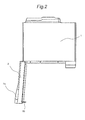
- Fig. 2 is a top view of the cooker with its handle-attached door 2 fully opened (in open state), as viewed from above.
- Fig. 3 is a front view of the cooker with its handle-attached door 2 fully opened.
- a heating cabinet 8 for heating a heating object 23 (see Fig. 4 ), which is to be heated, is provided.
- the heating cabinet 8 has an opening 8a on its front side, and the opening 8a is opened and closed by lateral pivoting of the handle-attached door 2.
- one side portion of the handle-attached door 2 opposite to the operation panel 3 side is pivotably attached via a hinge (not shown) to one side portion of the casing 1 opposite to the operation panel 3 side.
- Latch hooks 90 are provided on the rear face of the handle-attached door 2. When the handle-attached door 2 is closed, the latch hooks 90 are inserted into insertion holes 91 provided in peripheral portion of the opening 8a, so that the latch hooks 90 are disengageably engaged with a latch mechanism (not shown) within the casing 1. Also, disengagement of the latch hooks 90 can be done by the user's gripping the handle 2a of the handle-attached door 2.
- reference sign 80 denotes steam blowoff holes through which steam generated by a steam generator 13 (see Fig. 5 ) is blown off inward of the heating cabinet 8.
- Fig. 4 is a schematic sectional view of the cooker.
- part of the air within the heating cabinet 8 is discharged to the exhaust duct 100 via an exhaust port 8c and an exhaust tube 18 so as to be mixed and diluted in the exhaust duct 100 with the air that has come in through the cooling air inlet 101.
- the air diluted in the exhaust duct 100 is blown off from a plurality of discharge ports 102 provided in the exhaust duct 100 inward of one end portion of the dew receiving container 4.
- part of air flowing through the air flow passage 112 is blown off from a plurality of cooling-air blowoff ports 70 provided on the front side of the bottom plate of the casing 1, inward of one end portion of the dew receiving container 4.
- reference sign 26 denotes a heater 26 for heating the heating object 23.
- the inlet ports 17 are formed from slits, respectively, provided in rear portion of the casing 1.
- Fig. 5 is a perspective view of the cooker with its casing 1 removed, as viewed from rearward and obliquely upward.
- the electrical component chamber 9 is provided sideward of the heating cabinet 8 (see Figs. 3 and 4 ) and rearward of the operation panel 3.
- An inlet space 10 is provided sideward of the heating cabinet 8 and rearward of the electrical component chamber 9.
- the heater 26 for heating the heating object 23 is placed in an upper space within the heating cabinet 8.
- heat shielding plates 11, 11, ... are placed upward, downward, rearward and both sideward of the heating cabinet 8, respectively. That is, the heat shielding plates 11, 11, ... are placed all around the heating cabinet 8 except its opening 8a. Also, heat insulating material (not shown) is filled in spaces between the heat shielding plates 11 and the heating cabinet 8. In addition, in Fig. 5 , the heat shielding plate placed upward of the heating cabinet 8 is omitted in drawing.
- a steam generator 13 for generating steam is placed on the rear face side of the heating cabinet 8.
- a feedwater pump 19 connected to the steam generator 13 via a feedwater tube (not shown) is placed on the lower side of the heating cabinet 8.
- a tank accommodating part 15 for accommodating a feedwater tank (not shown), a magnetron 51, a power transformer 52 and the like are disposed in the electrical component chamber 9. Then, during heating of the heating object 23, cooling air from the cooling fan 16 flows within the electrical component chamber 9 so that the magnetron 51 and other electrical components can be cooled.
- Microwaves generated by the magnetron 51 are led to a lower center of the heating cabinet 8 via a waveguide (not shown) and, while being stirred by a rotating antenna (not shown), radiated upward within the heating cabinet 8 so as to heat the heating object 23.
- Water in the feedwater tank accommodated in the tank accommodating part 15 is fed to the steam generator 13 via a feedwater tube (not shown) by the feedwater pump 19.
- the steam generator 13 heats the water derived from the feedwater pump 19 by a steam generating heater 24 so as to generate steam.
- reference sign 21 denotes a partitioning wall for partitioning between the electrical component chamber 9 and the inlet space 10.
- the cooling fan 16 is mounted on the partitioning wall 21.
- Fig. 6 is a schematic view as the interior of the heating cabinet 8 is viewed from the opening 8a.
- a metal tray 201 and a glass tray 301 are settable into and out of the heating cabinet 8.
- Upper tray holders 31A, 31B are provided on the up side of inner surfaces of a right side wall 8d and a left side wall 8e of the heating cabinet 8, respectively, and these upper tray holders 31A, 31B hold the metal tray 201 from below.
- lower tray holders 32A, 32B are provided on the lower side of inner surfaces of the right side wall 8d and the left side wall 8e of the heating cabinet 8, respectively, and these lower tray holders 32A, 32B hold the glass tray 301 from below.
- the metal tray 201, while held by the upper tray holders 31A, 31B, is positioned at a height of e.g. about 23 cm from the installation plane of the cooker.
- the glass tray 301 while held by the lower tray holders 32A, 32B, is positioned at a height of e.g. about 15 cm from the installation plane of the cooker.
- the upper tray holders 31A, 31B are enabled to hold the glass tray 301 as well, while the lower tray holders 32A, 32B are enabled to hold the metal tray 201 as well.
- the metal tray 201 and the glass tray 301 are each an example of the tray.
- the upper tray holders 31A, 31B and the lower tray holders 32A, 32B are each an example of the holding part.
- Fig. 7 is a schematic top view of the metal tray 201 as viewed from above.
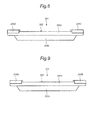
- Fig. 8 is a schematic right side view of the metal tray 201 as viewed from the right side.
- Fig. 9 is a schematic left side view of the metal tray 201 as viewed from the left side.
- the metal tray 201 has a tray body 202 made of a metal such as iron or stainless, and stoppers 203A, 203B, 203C, 203D made of a heat-resistant resin, while the outer peripheral edge of the metal tray 201 has a generally rectangular shape.
- the metal tray 201 can be set in either upper or lower part in the heating cabinet 8 so that the stoppers 203A, 203B are positioned deeper in the heating cabinet 8, or the metal tray 201 can be set in either upper or lower part in the heating cabinet 8 so that the stoppers 203C, 203D are positioned on the deeper side in the heating cabinet 8.
- the stoppers 203A, 203B, 203C, 203D are an example of a first stopper as well as an example of a second stopper.
- the tray body 202 is composed of a bottom portion 202a for mounting the heating object 23 thereon, a side portion 202b erectly provided all over the peripheral edge portion of the bottom portion 202a, and a flange portion 202c adjoining an upper end portion of the side portion 202b.
- a plurality of through holes 202d are provided in the bottom portion 202a so that water or other liquids do not accumulate on the bottom portion 202a.
- the four corner portions of the flange portion 202c are formed each into an arc-like shape in a top view. That is, outer peripheral edges of the four corner portions of the flange portion 202c are rounded.
- the stoppers 203A, 203B, 203C, 203D each having a sectoral shape as viewed from above, are placed on the corner portions of the flange portion 202c and fixed with screws 204.
- the stoppers 203A, 203B, 203C, 203D are slightly larger in width than the corner portions of the flange portion 202c, and there is a step gap between top faces of the stoppers 203A, 203B, 203C, 203D and a top face of the flange portion 202c. While the upper tray holders 31A, 31B hold the metal tray 201 from below and moreover the bottom portion 202a of the tray body 202 is generally horizontal, the corner portions of the flange portion 202c are kept from contact with upper surfaces of the upper tray holders 31A, 31B.
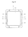
- Fig. 10 is a schematic top view of the glass tray 301 as viewed from above.
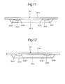
- Fig. 11 is a schematic right side view of the glass tray 301 as viewed from the right side.
- Fig. 12 is a schematic left side view of the glass tray 301 as viewed from the left side.
- the glass tray 301 has a bottom portion 301a for mounting the heating object 23 thereon, a right side portion 301b erectly provided at a right-side edge portion of the bottom portion 301a, a left side portion 301c erectly provided at a left-side edge portion of the bottom portion 301a, a plate-shaped right end portion 301d adjoining an upper end portion of the right side portion 301b, and a left end portion 301e adjoining an upper end portion of the left side portion 301c.
- No through holes are provided in the bottom portion 301a, so that water or other liquids can be held by the bottom portion 301a.
- outer peripheral edges of the four corner portions of the glass tray 301 are rounded.
- the glass tray 301 can be set in either upper or lower part in the heating cabinet 8 so that later-described stoppers 302A, 302B are positioned on the deeper side in the heating cabinet 8, or the glass tray 301 can be set in either upper or lower part in the heating cabinet 8 so that later-described stoppers 302C, 302D are positioned on the deeper side in the heating cabinet 8.
- the bottom portion 301a, the right side portion 301b, the left side portion 301c, the right end portion 301d, and the left end portion 301e are an example of the tray body.
- stoppers 302A, 302C having a trapezoidal shape as viewed sideways are provided on the lower surface of the right end portion 301d.
- the stopper 302A has a first inclined end face 303A on one side facing the stopper 302C.
- the sttopper 302A has a second inclined end face 304A on the side opposite to the stopper 302C side.
- the stopper 302C also has a first inclined end face 303C on one side facing the stopper 302A.
- the sttopper 302C has a second inclined end face 304C on the side opposite to the stopper 302A side.
- An inclination angle of the first inclined end faces 303A, 303C relative to the lower surface of the right end portion 301d is set larger than an inclination angle of the second inclined end faces 304A, 304C relative to the lower surface of the right end portion 301d.
- the stoppers 302A, 302C are an example of the first stopper.
- the first inclined end faces 303A, 303C are an example of a first end face.
- the second inclined end faces 304A, 304C are an example of a second end face.
- stoppers 302B, 302D having a trapezoidal shape as viewed sideways are provided on the lower surface of the left end portion 301e.
- the stopper 302B has a first inclined end face 303B on one side facing the stopper 302D.
- the sttopper 302B has a second inclined end face 304B on the side opposite to the stopper 302D side.
- the stopper 302D also has a first inclined end face 303D on one side facing the stopper 302B.
- the sttopper 302D has a second inclined end face 304D on the side opposite to the stopper 302B side.
- An inclination angle of the first inclined end faces 303B, 303D relative to the lower surface of the left end portion 301e is set larger than an inclination angle of the second inclined end faces 304B, 304D relative to the lower surface of the left end portion 301e.
- the stoppers 302B, 302D are an example of the first stopper.
- the first inclined end faces 303B, 303D are an example of the first end face.
- the second inclined end faces 304B, 304D are an example of the second end face.
- stoppers 302A and 302B or the pair of stoppers 302C and 302D serves for the role of restricting moves of the metal tray 201 in the heating cabinet 8.
- the stoppers 302A, 302B, 302C, 302D are protruding portions which protrude downward from the lower surface of the right end portion 301d or the left end portion 301e and which are formed by integral molding using heat-resistant glass material together with the bottom portion 301a, the right side portion 301b, the left side portion 301c, the right end portion 301d, the left end portion 301e, and the like.
- the lower surface of the left end portion 301e is a surface that is generally parallel to a pulling-in/out direction of the glass tray 301.
- Fig. 13 is a schematic view of the right side wall 8d of the heating cabinet 8 as viewed from the inner side.
- Fig. 14 is a schematic view of the left side wall 8e of the heating cabinet 8 as viewed from the inner side.
- the upper tray holders 31A, 31B and the lower tray holders 32A, 32B extend in straight lines from vicinities of the opening 8a of the heating cabinet 8 toward the rear portion of the heating cabinet 8. Also, the upper surfaces of the upper tray holders 31A, 31B and the upper surfaces of the lower tray holders 32A, 32B are inclined obliquely downward relative to the horizontal direction.
- the flange portion 202c of the tray body 202 of the metal tray 201 slides in contact on the upper surfaces of the upper tray holders 31A, 31B.
- the right end portion 301d and the left end portion 301e of the glass tray 301 slide in contact on the upper surfaces of the lower tray holders 32A, 32B.
- cylindrical-shaped first upper protrusions 33A, 33B are provided so as to be positioned upward of fore end portions of the upper tray holders 31A, 31B while cylindrical-shaped second upper protrusions 34A, 34B are provided so as to be positioned forward of the fore end portions of the upper tray holders 31A, 31B.
- first upper protrusions 33A, 33B and the second upper protrusions 34A, 34B are positioned close to the opening 8a of the heating cabinet 8.
- a diameter of the first upper protrusions 33A, 33B is set smaller than a diameter of the second upper protrusions 34A, 34B.
- Upper ends of the second upper protrusions 34A, 34B are generally flush with the upper surfaces of the upper tray holders 31A, 31B. Also, in a case where the metal tray 201 in the state that the stoppers 203A, 203B are positioned deeper than the stoppers 203C, 203D is pulled out from within the heating cabinet 8 by a horizontal move, when the metal tray 201 has been pulled out to a preset length from within the heating cabinet 8, the first upper protrusions 33A, 33B come into contact with fore end faces (end faces on the opening 8a side) of the stoppers 203A, 203B so that horizontal moves of the metal tray 201 are restricted.
- the first upper protrusions 33A, 33B come into contact with the upper surface of the flange portion 202c of the tray body 202 so that pivoting of the metal tray 201 is restricted.
- the first upper protrusions 33A, 33B and the second upper protrusions 34A, 34B are an example of restricting parts.
- cylindrical-shaped first lower protrusions 35A, 35B are provided so as to be positioned upward of the fore end portions of the lower tray holders 32A, 32B while cylindrical-shaped second lower protrusions 36A, 36B are provided so as to be positioned forward of the fore end portions of the lower tray holders 32A, 32B.
- first lower protrusions 35A, 35B and the second lower protrusions 36A, 36B are positioned close to the opening 8a of the heating cabinet 8.
- a diameter of the first lower protrusions 35A, 35B is set smaller than a diameter of the second lower protrusions 36A, 36B.
- the first lower protrusions 35A, 35B come into contact with the upper surfaces of the right end portion 301d and the left end portion 301e of the glass tray 301 so that pivoting of the glass tray 301 is restricted.
- the first lower protrusions 35A, 35B and the second lower protrusions 36A, 36B are an example of the restricting parts.
- the metal tray 201 is put in upper part within the heating cabinet 8 so that the stoppers 203A, 203B are positioned on the deeper side (rear side) in the heating cabinet 8, by which the metal tray 201 is held by the upper tray holders 31A, 31B.
- the glass tray 301 is put in lower part within the heating cabinet 8 so that the stoppers 302A, 302B are positioned on the deeper side (rear side) in the heating cabinet 8, by which the glass tray 301 is held by the lower tray holders 32A, 32B.
- the handle-attached door 2 is closed and a plurality of press buttons on the operation panel 3 are operated, by which the heating object 23 is steamed.
- condensed water or the like generated on the metal tray 201 drips through the plurality of through holes 202d of the bottom portion 202a of the tray body 202, accumulating on the bottom portion 202a of the glass tray 301.
- the handle-attached door 2 is opened and the metal tray 201 is pulled out to take out the heating object 23 from within the heating cabinet 8
- the first upper protrusions 33A, 33B come into contact with the fore end faces of the stoppers 203A, 203B, inhibiting the metal tray 201 from being pulled out.
- the metal tray 201 and the heating object 23 can be prevented from falling off due to the user's erroneous, excessive pull-out of the metal tray 201.
- the metal tray 201 in the state of Figs. 15 and 16 , even if the metal tray 201 is induced to pivot about near the second upper protrusions 34A, 34B by its self weight, the first upper protrusions 33A, 33B come into contact with the upper surface of the flange portion 202c so that such pivoting of the metal tray 201 can be prevented. Therefore, even without the user's holding of the metal tray 201, it becomes possible to hold the state that most of the metal tray 201 has come out of the heating cabinet 8. Accordingly, since the user is allowed to freely use both hands in the above-described state, it becomes possible to easily take out the heating object 23 from the metal tray 201. For example, in the state of Figs. 15 and 16 , even when a weight of 2 kg is placed on the forward side of the metal tray 201 with the hands off the metal tray 201, the metal tray 201 can be prevented from tilting down.
- the heating object 23 can be taken out in the state of Figs. 15 and 16 , takeout of the heating object 23 can be fulfilled without giving considerations for the rest place for the metal tray 201 even in a narrow kitchen as an example, hence an improved usability.
- tilting the metal tray 201 as shown in Figs. 17 and 18 causes the first upper protrusions 33A, 33B to be released from contact therewith. That is, the stoppers 203A, 203B go apart from the first upper protrusions 33A, 33B. Therefore, the stoppers 203A, 203B are allowed to go through under the first upper protrusions 33A, 33B, so that the metal tray 201 can entirely be taken out of the heating cabinet 8. As a result, the metal tray 201 can be easily cleaned outside the heating cabinet 8 and moreover the heating object 23 can be easily rested on the bottom portion 202a of the tray body 202.
- stoppers 203A, 203B are placed on the flange portion 202c, it becomes easily achievable to discern the contact state of the first upper protrusions 33A, 33B with the stoppers 203A, 203B. Thus, it becomes easily achievable to do the tilting operation of the metal tray 201 for releasing the contact of the first upper protrusions 33A, 33B.
- stoppers 203A, 203B are positioned on the corner portions of the flange portion 202c, the stoppers 203A, 203B can securely be released from the first upper protrusions 33A, 33B by tilting the metal tray 201.
- first upper protrusions 33A, 33B are positioned close to the opening 8a of the heating cabinet 8, it follows that when the first upper protrusions 33A, 33B have come into contact with the stoppers 203A, 203B so that the metal tray 201 has been stopped, most part of the metal tray 201 can securely be taken out of the heating cabinet 8. Thus, the heating object 23 can more easily be taken out from the metal tray 201.
- the metal tray 201 is put in upper part within the heating cabinet 8 so that the stoppers 203A, 203B are positioned on the deeper side (rear side) in the heating cabinet 8, tilting the metal tray 201 about the second upper protrusions 34A, 34B as shown in Figs. 17 and 18 allows the stoppers 203A, 203B to go through under the first upper protrusions 33A, 33B, in which state the metal tray 201 is pushd into the heating cabinet 8. Then, as shown in Figs. 19 and 20 , the first upper protrusions 33A, 33B come into contact with rear end faces of the stoppers 203C, 203D, inhibiting the metal tray 201 from being pushd into the heating cabinet 8. As a result, the metal tray 201 can securely be set to a predetermined place, making it possible to securely fulfill a target heating of the heating object 23 on the bottom portion 202a.
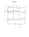
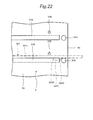
- the glass tray 301 in the case where the glass tray 301 is pulled out, when part (e.g., less than a half) of the glass tray 301 has come out of the heating cabinet 8 as shown in Figs. 21 and 22 , the second lower protrusions 36A, 36B come into contact with the second inclined end faces 304C, 304D of the stoppers 302C, 302D. In this state, further pulling the glass tray 301 causes the second inclined end faces 304C, 304D of the stoppers 302C, 302D to slide in contact with the second lower protrusions 36A, 36B, so that the stoppers 302C, 302D go beyond the second lower protrusions 36A, 36B. Therefore, the glass tray 301 can be further pulled out from within the heating cabinet 8. Thus, the glass tray 301 can be pulled out relatively smoothly from within the heating cabinet 8.
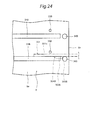
- the glass tray 301 is further pulled out, when most part (e.g., more than a half) of the glass tray 301 has come out of the heating cabinet 8 as shown in Figs. 23 and 24 , the second lower protrusions 36A, 36B come into contact with the first inclined end faces 303A, 303B of the stoppers 302A, 302B, inhibiting the glass tray 301 from being pulled out.
- the glass tray 301 can be prevented from falling off due to the user's erroneous, excessive pull-out of the glass tray 301.
- the glass tray 301 in the state of Figs. 23 and 24 even if the glass tray 301 is induced to pivot about near the second lower protrusions 36A, 36B by its self weight, the first lower protrusions 35A, 35B come into contact with the upper surfaces of the right end portion 301d and the left end portion 301e so that such pivoting of the glass tray 301 can be prevented. Therefore, even without the user's holding of the glass tray 301, it becomes possible to hold the state that most of the glass tray 301 has come out of the heating cabinet 8. Accordingly, on condition that the heating object 23 is mounted on the glass tray 301, the user is allowed to easily take out the heating object 23 from the glass tray 301 as it is in the above state. For example, in the state of Figs. 23 and 24 , even when a weight of 2 kg is placed on the forward side of the glass tray 301 with the hands off the glass tray 301, the glass tray 301 can be prevented from tilting down.
- the heating object 23 can be taken out in the state of Figs. 23 and 24 , takeout of the heating object 23 can be fulfilled without giving considerations for the rest place for the glass tray 301 even in a narrow kitchen as an example, hence an improved usability.
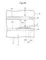
- tilting the glass tray 301 as shown in Figs. 25 and 26 causes the second lower protrusions 36A, 36B to be released from contact therewith. That is, the stoppers 302A, 302B go apart from the second lower protrusions 36A, 36B. Therefore, the stoppers 302A, 302B are allowed to go beyond the second lower protrusions 36A, 36B, so that the glass tray 301 can entirely be taken out of the heating cabinet 8. As a result, the heating object 23 can be easily rested on the bottom portion 301a of the glass tray 301, and moreover the glass tray 301 can be easily cleaned outside the heating cabinet 8.
- the glass tray 301 is set in lower part within the heating cabinet 8 so that the stoppers 302A, 302B are positioned on the deeper side (rear side) in the heating cabinet 8, the second lower protrusions 36A, 36B come into contact with the second inclined end faces 304A, 304B of the stoppers 302A, 302B as shown in Figs. 27 and 28 .
- further pushing the glass tray 301 causes the second inclined end faces 304A, 304B of the stoppers 302A, 302B to slide in contact with the second lower protrusions 36A, 36B, so that the stoppers 302A, 302B go beyond the second lower protrusions 36A, 36B. Therefore, the glass tray 301 can be further put into the heating cabinet 8.
- the glass tray 301 can be put relatively smoothly into the heating cabinet 8.
- the first inclined end faces 303C, 303D of the stoppers 302C, 302D come into contact with the second lower protrusions 36A, 36B.
- tilting the glass tray 301 as in the case of Figs. 25 and 26 causes the second lower protrusions 36A, 36B to be released from contact therewith. That is, the stoppers 302C, 302D go apart from the second lower protrusions 36A, 36B. Therefore, the stoppers 302C, 302D are allowed to go beyond the second lower protrusions 36A, 36B, so that the glass tray 301 can entirely be put in lower part within the heating cabinet 8.
- stoppers 302A, 302C are provided on the lower surface of the right end portion 301d while the stoppers 302B, 302D are provided on the lower surface of the left end portion 301e, it becomes possible to use the glass tray 301 as the metal tray 201 is superimposed thereon for example. Thus, the convenience of the glass tray 301 can be improved.
- stoppers 302A, 302C are provided on the lower surface of the right end portion 301d while the stoppers 302B, 302D are provided on the lower surface of the left end portion 301e, it follows that the stoppers 302A, 302B, 302C, 302D are less noticeable as the glass tray 301 is viewed from above, so that the glass tray 301 can be prevented from degrading in appearance.
- stoppers 302A, 302B, 302C, 302D are made by integral molding using heat-resistant glass material together with the bottom portion 301a, the right side portion 301b, the left side portion 301c, the right end portion 301d, the left end portion 301e and the like, it follows that manufacturing steps for the glass tray 301 can be reduced so that manufacturing cost for the glass tray 301 can be reduced.
- the second lower protrusions 36A, 36B are positioned near the opening 8a of the heating cabinet 8, it follows that when the glass tray 301 has stopped due to contact of the second lower protrusions 36A, 36B with the stoppers 302A, 302B, most part of the glass tray 301 can securely be put out of the heating cabinet 8. Accordingly, on condition that the heating object 23 is mounted on the glass tray 301, the heating object 23 can be taken out more easily from the glass tray 301.
- the glass tray 301 is provided with no stopper for its positioning within the heating cabinet 8 in this embodiment, yet the glass tray 301 may be provided with a stopper for fulfilling the positioning within the heating cabinet 8.
- the metal tray 201 is set in upper part within the heating cabinet 8 so that the stoppers 203A, 203B are positioned on the deeper side in the heating cabinet 8.
- the metal tray 201 can also be set in upper part within the heating cabinet 8 so that the stoppers 203C, 203D are positioned on the deeper side in the heating cabinet 8.
- the same functional effects can be obtained as in the case where the metal tray 201 is set in upper part within the heating cabinet 8 so that the stoppers 203A, 203B are positioned on the deeper side in the heating cabinet 8.
- the glass tray 301 is set in lower part within the heating cabinet 8 so that the stoppers 302A, 302B are positioned on the deeper side in the heating cabinet 8.
- the glass tray 301 can also be set in lower part within the heating cabinet 8 so that the stoppers 302C, 302D are positioned on the deeper side in the heating cabinet 8.
- the same functional effects can be obtained as in the case where the glass tray 301 is set in lower part within the heating cabinet 8 so that the stoppers 302A, 302B are positioned on the deeper side in the heating cabinet 8.
- the metal tray 201 is held by the upper tray holders 31A, 31B in this embodiment, yet the glass tray 301 can also be held by the upper tray holders 31A, 31B.
- the same functional effects can be obtained as in the case where the glass tray 301 is held by the lower tray holders 32A, 32B.
- the glass tray 301 is held by the lower tray holders 32A, 32B in this embodiment, yet the metal tray 201 can also be held by the lower tray holders 32A, 32B.
- the same functional effects can be obtained as in the case where the glass tray 301 is held by the lower tray holders 32A, 32B.
- Both the first upper protrusions 33A, 33B and the second upper protrusions 34A, 34B are provided on the inner surface of the heating cabinet 8 in this embodiment. However, only one of the first upper protrusions 33A, 33B and the second upper protrusions 34A, 34B may be provided on the inner surface of the heating cabinet 8.
- Both the first lower protrusions 35A, 35B and the second lower protrusions 36A, 36B are provided on the inner surface of the heating cabinet 8 in this embodiment. However, only one of the first lower protrusions 35A, 35B and the second lower protrusions 36A, 36B may be provided on the inner surface of the heating cabinet 8.
- the contact of the first upper protrusions 33A, 33B with the fore end faces of the stoppers 203A, 203B is released by tilting the metal tray 201 so that the forward side of the metal tray 201 becomes higher than the deeper side of the metal tray 201 in this embodiment.
- shape or position of the first upper protrusions 33A, 33B, the stoppers 203A, 203B and the like may be changed in such a fashion that the contact is released by tilting the metal tray 201 so that the deeper side of the metal tray 201 becomes higher than the forward side of the metal tray 201.
- the contact of the second lower protrusions 36A, 36B with the first inclined end faces 303A, 303B of the stoppers 302A, 302B is released by tilting the glass tray 301 so that the forward side of the glass tray 301 becomes higher than the deeper side of the glass tray 301 in this embodiment.
- shape or position of the second lower protrusions 36A, 36B, the stoppers 302A, 302B and the like may be changed in such a fashion that the contact is released by tilting the glass tray 301 so that the deeper side of the glass tray 301 becomes higher than the forward side of the glass tray 301.
- the present invention is applicable to, for example, not only ovens, cooking ranges, microwave ovens and other cookers using steam or superheated steam, but also ovens, cooking ranges, microwave ovens and other cookers using neither steam nor superheated steam.
Landscapes
- Engineering & Computer Science (AREA)
- Chemical & Material Sciences (AREA)
- Combustion & Propulsion (AREA)
- Mechanical Engineering (AREA)
- General Engineering & Computer Science (AREA)
- Electric Ovens (AREA)
- Baking, Grill, Roasting (AREA)
Abstract
Description
- The present invention relates to a cooker.
- Conventionally, there has been provided a cooker which includes a heating cabinet having an opening on its front side, a tray to be removably placed in the heating cabinet for mounting thereon a heating object, which is to be heated, and tray holders provided on individual side faces of the heating cabinet to hold the tray from below (see, e.g.,
JP 2011-163697 A - The tray holders, extending from proximities of the opening on the front side of the heating cabinet to proximities of a rear-end wall of the heating cabinet, serve also for guiding the tray into the heating cabinet when the tray is put into the heating cabinet.
- PTL1:
JP 2011-163697 A - Unfortunately, with the above-described cooker, when the tray is put out from within the heating cabinet, fore end portions of the tray holders are hidden invisible by the tray because the tray holders are positioned below the tray. As a result, there is a problem that the user may excessively pull out the tray erroneously, so that the tray, or the heating object on the tray, may be fallen off.
- Accordingly, an object of the present invention is to provide a cooker capable of preventing the tray and heating objects from falling off.
- In order to achieve the objective of the present invention, a cooker according to the present invention comprises
a casing;
a heating cabinet provided in the casing and having an opening on its front side;
a door for opening and closing the opening (8a) of the heating cabinet;
a tray to be removably placed in the heating cabinet for mounting thereon a heating object, which is to be heated;
holding parts provided on an inner surface of the heating cabinet and serving for holding the tray in the heating cabinet; and
restricting parts provided on the inner surface of the heating cabinet and serving for, when put into contact with part of the tray, restricting forward moves of the tray, wherein
in process of pulling out the tray from within the heating cabinet, the tray is tilted in a direction other than a forward direction in a state that the restricting parts are in contact with the part of the tray, whereby the contact of the restricting parts with the part of the tray is released, thus allowing the tray to be pulled out of the heating cabinet. - With this constitution, in process of pulling out the tray from within the heating cabinet, before the entirety of the tray comes out of the heating cabinet, the restricting parts make contact with the part of the tray, by which forward moves of the tray are restricted. Accordingly, even if the front sides of the holding parts are hidden invisible by the tray, the tray and the heating object can be prevented from falling off due to the user's erroneous, excessive pull-out of the tray.
- Also, in process of pulling out the tray from within the heating cabinet, the tray is tilted in a direction other than a forward direction in a state that the restricting parts are in contact with the part of the tray, whereby the contact of the restricting parts with the part of the tray is released, thus allowing the tray to be pulled out of the heating cabinet. As a result, the tray can be easily cleaned outside the heating cabinet and moreover the heating object can be easily mounted on the tray.
- In a cooker according to one embodiment,
the restricting parts are to be put into contact with an upper side of the tray to restrict vertical pivoting of the tray. - According to this embodiment, the restricting parts make contact with the upper side of the tray to restrict vertical pivoting of the tray. Thus, even if The user does not hold the tray, the tray can be prevented from tilting down due to pivoting by its self weight.
- Also, since the tray can be prevented from tilting down due to pivoting by its self weight even without the user's holding the tray, the user can easily take out the heating object from the tray by using both hands.
- In a cooker according to one embodiment,
the tray has a tray body, and first stoppers provided on the tray body, and
the part of the tray serves as the first stoppers. - According to this embodiment, since the restricting parts make contact with the first stoppers provided on the tray body, forward moves of the tray can securely be restricted.
- In a cooker according to one embodiment,
the first stoppers are provided on a lower surface of the tray body. - According to this embodiment, since the first stoppers are provided on the lower surface of the tray, the first stoppers are less noticeable as the tray is viewed from above, so that the tray can be prevented from degrading in appearance.
- In a cooker according to one embodiment,
the first stoppers have first end faces which are to be put into contact with the restricting parts when the tray is pulled out from within the heating cabinet, and second end faces which are to be put into contact with the restricting parts when the tray is put into the heating cabinet, and
an angle formed by the second end faces of the first stoppers against a pulling-in/out direction of the tray is smaller than an angle formed by the first end faces of the first stoppers against the pulling-in/out direction of the tray. - According to this embodiment, in process of pulling out the tray from within the heating cabinet, since the angle formed by the first end faces of the first stoppers against the pulling-in/out direction of the tray is larger than the angle formed by the second end faces of the first stoppers against the pulling-in/out direction of the tray, the first end faces of the first stoppers make contact with the restricting parts, thus being enabled to restrict moves of the tray. Meanwhile, in process of pulling the tray into the heating cabinet, since the angle formed by the second end faces of the first stoppers against the pulling-in/out direction of the tray is smaller than the angle formed by the first end faces of the first stoppers against the pulling-in/out direction of the tray, the second end faces of the first stoppers make sliding contact with the restricting parts, thus allowing the first stoppers to go beyond the restricting parts. Thus, the tray can be pulled relatively smoothly into the heating cabinet.
- In a cooker according to one embodiment,
the first stoppers are provided on an upper surface of the tray body. - According to this embodiment, since the first stoppers are provided on the upper surface of the tray body, it becomes easily achievable to discern the contact state of the restricting parts with the first stoppers. Thus, it becomes easily achievable to do the tilting operation of the tray for releasing the contact of the restricting parts.
- In a cooker according to one embodiment,
an outer peripheral edge of the tray has a generally rectangular shape, and
the first stoppers are positioned at rear-side corner portions of the tray. - According to this embodiment, since the first stoppers are positioned at rear-side corner portions of the tray, the contact of the restricting parts with the first stoppers can securely be released by tilting the tray.
- In a cooker according to one embodiment,
the four corner portions of the tray are generally identical in shape to one another. - According to this embodiment, since the four corner portions of the tray are generally identical in shape to one another, positioning of the tray for its pull-in into the heating cabinet does not need to be determined uniquely, hence an improved usability.
- In a cooker according to one embodiment,
the tray has second stoppers for positioning in the heating cabinet. - According to this embodiment, since the tray can be positioned in the heating cabinet by the second stoppers, a target heating of the heating object can securely be achieved.
- In a cooker according to one embodiment,
the first stoppers are provided integrally with the tray body. - According to this embodiment, since the first stoppers are provided integrally with the tray body, the first stoppers and the tray body can be obtained by integral molding. Thus, manufacturing steps for the tray can be reduced so that manufacturing cost for the tray can be reduced.
- In a cooker according to one embodiment,
the restricting parts are positioned near the opening of the heating cabinet. - According to this embodiment, while the restricting parts are in contact with the first stoppers so as to restrict forward moves of the tray, the restricting parts are positioned near the opening of the heating cabinet, so that most part of the tray can be protruded from the heating cabinet. Thus, the heating object can be taken out more easily from the tray.
- In a cooker according to one embodiment of the cooker,
the restricting parts include a protruding portion positioned upward of the holding parts, and a protruding portion positioned forward of the holding parts. - According to this embodiment, since the restricting parts include a protruding portion positioned upward of the holding parts, and a protruding portion positioned forward of the holding parts, there can be obtained, with a simple structure, an effect that the tray and the heating object can be prevented from falling off, an effect that the tray can be easily cleaned outside the heating cabinet, and an effect that the heating object can be easily mounted on the tray.
- In a cooker according to one embodiment of the cooker,
the contact of the restricting parts can be released by tilting the tray so that the forward side of the tray becomes higher than the deeper side of the tray. - According to this embodiment, with the heating object mounted on the tray, tilting the tray so that the forward side of the tray becomes higher than the deeper side of the tray causes the contact of the restricting parts to be released. Thus, in process of releasing the contact of the restricting parts, the heating object can be prevented from moving toward the forward side of the tray and dropping off from the tray.
- The cooker of the present invention includes: a casing; a heating cabinet provided in the casing and having an opening on its front side; a door for opening and closing the opening of the heating cabinet; a tray to be removably placed in the heating cabinet for mounting thereon a heating object, which is to be heated; holding parts provided on an inner surface of the heating cabinet and serving for holding the tray in the heating cabinet; and restricting parts provided on the inner surface of the heating cabinet and serving for, when put into contact with part of the tray, restricting forward moves of the tray. Thus, the cooker is enabled to prevent the tray and the heating object from falling off.
- Also, in process of pulling out the tray from within the heating cabinet, the tray is tilted in a direction other than a forward direction in a state that the restricting parts are in contact with part of the tray, whereby the contact of the restricting parts with part of the tray is released, thus allowing the tray to be pulled out of the heating cabinet. Thus, the tray can be easily cleaned outside the heating cabinet and moreover the heating object can be easily mounted on the tray.
-
-
Fig. 1 is a front view of a cooker according to an embodiment of the present invention; -
Fig. 2 is a top view of the cooker with its handle-attached door opened; -
Fig. 3 is a front view of the cooker with its handle-attached door opened; -
Fig. 4 is a schematic sectional view of the cooker; -
Fig. 5 is a perspective view of the cooker with its casing removed; -
Fig. 6 is a schematic view of the cooker as the interior of its heating cabinet is viewed from the opening side; -
Fig. 7 is a schematic top view of a metal tray of the cooker; -
Fig. 8 is a schematic right side view of the metal tray; -
Fig. 9 is a schematic left side view of the metal tray; -
Fig. 10 is a schematic top view of a glass tray of the cooker; -
Fig. 11 is a schematic right side view of the glass tray; -
Fig. 12 is a schematic left side view of the glass tray; -
Fig. 13 is a schematic view of a right side wall of the heating cabinet as viewed from the inner side; -
Fig. 14 is a schematic view of a left side wall of the heating cabinet as viewed from the inner side; -
Fig. 15 is a schematic view for explaining extracting operation of the metal tray; -
Fig. 16 is a schematic view for explaining extracting operation of the metal tray; -
Fig. 17 is a schematic view for explaining extracting operation of the metal tray; -
Fig. 18 is a schematic view for explaining extracting operation of the metal tray; -
Fig. 19 is a schematic view for explaining inserting operation of the metal tray; -
Fig. 20 is a schematic view for explaining inserting operation of the metal tray; -
Fig. 21 is a schematic view for explaining extracting operation of the glass tray; -
Fig. 22 is a schematic view for explaining extracting operation of the glass tray; -
Fig. 23 is a schematic view for explaining extracting operation of the glass tray; -
Fig. 24 is a schematic view for explaining extracting operation of the glass tray; -
Fig. 25 is a schematic view for explaining extracting operation of the glass tray; -
Fig. 26 is a schematic view for explaining extracting operation of the glass tray; -
Fig. 27 is a schematic view for explaining inserting operation of the glass tray; and -
Fig. 28 is a schematic view for explaining inserting operation of the glass tray. - Hereinbelow, a cooker of the present invention will be described in detail by embodiments thereof illustrated in the accompanying drawings.
-
Fig. 1 is a front view of a cooker according to an embodiment of the invention. - The cooker includes a
casing 1, and a handle-attacheddoor 2 mounted on the front side of thecasing 1. A heat-resistant glass 5 is mounted at a generally center of the handle-attacheddoor 2. Also on the front side of thecasing 1, anoperation panel 3 is provided so as to be next to the closed handle-attacheddoor 2. Then, adew receiving container 4 is set below the handle-attacheddoor 2 and theoperation panel 3. In addition, the handle-attacheddoor 2 is an example of a door. - The
operation panel 3 has an LCD (Liquid Crystal Display)part 7, which makes displays in response to operations. Although not shown, a plurality of press buttons and the like are provided on theoperation panel 3. - The
dew receiving container 4 is a container fittable to and removable from twofront legs casing 1. Then, as thedew receiving container 4 is inserted to the lower side of thecasing 1 from forward to rearward so as to be fitted to thefront legs dew receiving container 4 is partly positioned below the rear face (back face) of the closed handle-attacheddoor 2. -
Fig. 2 is a top view of the cooker with its handle-attacheddoor 2 fully opened (in open state), as viewed from above.Fig. 3 is a front view of the cooker with its handle-attacheddoor 2 fully opened. - In the
casing 1 shown inFigs. 2 and3 , aheating cabinet 8 for heating a heating object 23 (seeFig. 4 ), which is to be heated, is provided. Theheating cabinet 8 has anopening 8a on its front side, and theopening 8a is opened and closed by lateral pivoting of the handle-attacheddoor 2. In this case, one side portion of the handle-attacheddoor 2 opposite to theoperation panel 3 side is pivotably attached via a hinge (not shown) to one side portion of thecasing 1 opposite to theoperation panel 3 side. - Latch hooks 90 are provided on the rear face of the handle-attached
door 2. When the handle-attacheddoor 2 is closed, the latch hooks 90 are inserted into insertion holes 91 provided in peripheral portion of theopening 8a, so that the latch hooks 90 are disengageably engaged with a latch mechanism (not shown) within thecasing 1. Also, disengagement of the latch hooks 90 can be done by the user's gripping thehandle 2a of the handle-attacheddoor 2. - In addition, in
Fig. 3 ,reference sign 80 denotes steam blowoff holes through which steam generated by a steam generator 13 (seeFig. 5 ) is blown off inward of theheating cabinet 8. -
Fig. 4 is a schematic sectional view of the cooker. - In this cooker, air outside the
casing 1 is sucked into thecasing 1 via a plurality ofinlet ports 17 by a coolingfan 16. Part of air sucked into thecasing 1 via the plurality ofinlet ports 17 passes through anelectrical component chamber 9 and then, with anair supply damper 50 opened, flows into theheating cabinet 8 through a plurality of open-stateair supply opening 8b. Meanwhile, another part of the air sucked into thecasing 1 via the plurality ofinlet ports 17, after passing through theelectrical component chamber 9, flows to the bottom side of thecasing 1 so as to flow into a coolingair inlet 101 of anexhaust duct 100 via anair flow passage 112 on the lower side of theheating cabinet 8. - Also, part of the air within the
heating cabinet 8 is discharged to theexhaust duct 100 via anexhaust port 8c and anexhaust tube 18 so as to be mixed and diluted in theexhaust duct 100 with the air that has come in through the coolingair inlet 101. The air diluted in theexhaust duct 100 is blown off from a plurality ofdischarge ports 102 provided in theexhaust duct 100 inward of one end portion of thedew receiving container 4. - In this process, part of air flowing through the
air flow passage 112 is blown off from a plurality of cooling-air blowoff ports 70 provided on the front side of the bottom plate of thecasing 1, inward of one end portion of thedew receiving container 4. - In addition, in
Fig. 4 ,reference sign 26 denotes aheater 26 for heating theheating object 23. Also, theinlet ports 17 are formed from slits, respectively, provided in rear portion of thecasing 1. -
Fig. 5 is a perspective view of the cooker with itscasing 1 removed, as viewed from rearward and obliquely upward. - In the
casing 1, theelectrical component chamber 9 is provided sideward of the heating cabinet 8 (seeFigs. 3 and4 ) and rearward of theoperation panel 3. Aninlet space 10 is provided sideward of theheating cabinet 8 and rearward of theelectrical component chamber 9. - In an upper space within the
heating cabinet 8, theheater 26 for heating theheating object 23 is placed. - Meanwhile, outside the
heating cabinet 8,heat shielding plates heating cabinet 8, respectively. That is, theheat shielding plates heating cabinet 8 except itsopening 8a. Also, heat insulating material (not shown) is filled in spaces between theheat shielding plates 11 and theheating cabinet 8. In addition, inFig. 5 , the heat shielding plate placed upward of theheating cabinet 8 is omitted in drawing. - Further, a
steam generator 13 for generating steam is placed on the rear face side of theheating cabinet 8. Afeedwater pump 19 connected to thesteam generator 13 via a feedwater tube (not shown) is placed on the lower side of theheating cabinet 8. - A
tank accommodating part 15 for accommodating a feedwater tank (not shown), amagnetron 51, apower transformer 52 and the like are disposed in theelectrical component chamber 9. Then, during heating of theheating object 23, cooling air from the coolingfan 16 flows within theelectrical component chamber 9 so that themagnetron 51 and other electrical components can be cooled. - Microwaves generated by the
magnetron 51 are led to a lower center of theheating cabinet 8 via a waveguide (not shown) and, while being stirred by a rotating antenna (not shown), radiated upward within theheating cabinet 8 so as to heat theheating object 23. - Water in the feedwater tank accommodated in the
tank accommodating part 15 is fed to thesteam generator 13 via a feedwater tube (not shown) by thefeedwater pump 19. Thesteam generator 13 heats the water derived from thefeedwater pump 19 by asteam generating heater 24 so as to generate steam. - As the cooling
fan 16 is driven, air outside thecasing 1 flows into theinlet space 10 through the plurality of inlet ports 17 (seeFig. 4 ). Then, air within theinlet space 10 is fed into theelectrical component chamber 9 by the coolingfan 16. - In addition, in
Fig. 5 ,reference sign 21 denotes a partitioning wall for partitioning between theelectrical component chamber 9 and theinlet space 10. The coolingfan 16 is mounted on thepartitioning wall 21. -
Fig. 6 is a schematic view as the interior of theheating cabinet 8 is viewed from theopening 8a. - A
metal tray 201 and aglass tray 301 are settable into and out of theheating cabinet 8.Upper tray holders right side wall 8d and aleft side wall 8e of theheating cabinet 8, respectively, and theseupper tray holders metal tray 201 from below. Further,lower tray holders right side wall 8d and theleft side wall 8e of theheating cabinet 8, respectively, and theselower tray holders glass tray 301 from below. Themetal tray 201, while held by theupper tray holders glass tray 301, while held by thelower tray holders upper tray holders glass tray 301 as well, while thelower tray holders metal tray 201 as well. In addition, themetal tray 201 and theglass tray 301 are each an example of the tray. Theupper tray holders lower tray holders -
Fig. 7 is a schematic top view of themetal tray 201 as viewed from above.Fig. 8 is a schematic right side view of themetal tray 201 as viewed from the right side.Fig. 9 is a schematic left side view of themetal tray 201 as viewed from the left side. - The
metal tray 201, as shown inFigs. 7 to 9 , has atray body 202 made of a metal such as iron or stainless, andstoppers metal tray 201 has a generally rectangular shape. Four corner portions of themetal tray 201 are generally identical in shape to one another. Also, themetal tray 201 can be set in either upper or lower part in theheating cabinet 8 so that thestoppers heating cabinet 8, or themetal tray 201 can be set in either upper or lower part in theheating cabinet 8 so that thestoppers heating cabinet 8. In addition, thestoppers - The
tray body 202 is composed of abottom portion 202a for mounting theheating object 23 thereon, aside portion 202b erectly provided all over the peripheral edge portion of thebottom portion 202a, and aflange portion 202c adjoining an upper end portion of theside portion 202b. A plurality of throughholes 202d are provided in thebottom portion 202a so that water or other liquids do not accumulate on thebottom portion 202a. Also, the four corner portions of theflange portion 202c are formed each into an arc-like shape in a top view. That is, outer peripheral edges of the four corner portions of theflange portion 202c are rounded. - Either the pair of
stoppers stoppers heating cabinet 8, serves for the role of restricting moves of themetal tray 201 in theheating cabinet 8, while the pair positioned on the forward side in theheating cabinet 8 serves for the role of positioning themetal tray 201 in theheating cabinet 8. Also, thestoppers flange portion 202c and fixed withscrews 204. Also, thestoppers flange portion 202c, and there is a step gap between top faces of thestoppers flange portion 202c. While theupper tray holders metal tray 201 from below and moreover thebottom portion 202a of thetray body 202 is generally horizontal, the corner portions of theflange portion 202c are kept from contact with upper surfaces of theupper tray holders -
Fig. 10 is a schematic top view of theglass tray 301 as viewed from above.Fig. 11 is a schematic right side view of theglass tray 301 as viewed from the right side.Fig. 12 is a schematic left side view of theglass tray 301 as viewed from the left side. - The
glass tray 301, as shown inFig. 10 , has abottom portion 301a for mounting theheating object 23 thereon, aright side portion 301b erectly provided at a right-side edge portion of thebottom portion 301a, aleft side portion 301c erectly provided at a left-side edge portion of thebottom portion 301a, a plate-shapedright end portion 301d adjoining an upper end portion of theright side portion 301b, and aleft end portion 301e adjoining an upper end portion of theleft side portion 301c. No through holes are provided in thebottom portion 301a, so that water or other liquids can be held by thebottom portion 301a. Also, outer peripheral edges of the four corner portions of theglass tray 301 are rounded. Theglass tray 301 can be set in either upper or lower part in theheating cabinet 8 so that later-describedstoppers heating cabinet 8, or theglass tray 301 can be set in either upper or lower part in theheating cabinet 8 so that later-describedstoppers heating cabinet 8. In addition, thebottom portion 301a, theright side portion 301b, theleft side portion 301c, theright end portion 301d, and theleft end portion 301e are an example of the tray body. - As shown in
Fig. 11 ,stoppers right end portion 301d. Thestopper 302A has a first inclined end face 303A on one side facing thestopper 302C. On the other hand, thesttopper 302A has a second inclined end face 304A on the side opposite to thestopper 302C side. Also, like thestopper 302A, thestopper 302C also has a first inclined end face 303C on one side facing thestopper 302A. On the other hand, thesttopper 302C has a second inclined end face 304C on the side opposite to thestopper 302A side. An inclination angle of the first inclined end faces 303A, 303C relative to the lower surface of theright end portion 301d is set larger than an inclination angle of the second inclined end faces 304A, 304C relative to the lower surface of theright end portion 301d. In addition, thestoppers - As shown in
Fig. 12 ,stoppers left end portion 301e. Thestopper 302B has a first inclined end face 303B on one side facing thestopper 302D. On the other hand, thesttopper 302B has a second inclined end face 304B on the side opposite to thestopper 302D side. Also, like thestopper 302B, thestopper 302D also has a firstinclined end face 303D on one side facing thestopper 302B. On the other hand, thesttopper 302D has a secondinclined end face 304D on the side opposite to thestopper 302B side. An inclination angle of the first inclined end faces 303B, 303D relative to the lower surface of theleft end portion 301e is set larger than an inclination angle of the second inclined end faces 304B, 304D relative to the lower surface of theleft end portion 301e. In addition, thestoppers - Either the pair of
stoppers stoppers heating cabinet 8, serves for the role of restricting moves of themetal tray 201 in theheating cabinet 8. Also, thestoppers right end portion 301d or theleft end portion 301e and which are formed by integral molding using heat-resistant glass material together with thebottom portion 301a, theright side portion 301b, theleft side portion 301c, theright end portion 301d, theleft end portion 301e, and the like. - In addition, the lower surface of the
left end portion 301e is a surface that is generally parallel to a pulling-in/out direction of theglass tray 301. -
Fig. 13 is a schematic view of theright side wall 8d of theheating cabinet 8 as viewed from the inner side.Fig. 14 is a schematic view of theleft side wall 8e of theheating cabinet 8 as viewed from the inner side. - As shown in
Figs. 13 and14 , theupper tray holders lower tray holders opening 8a of theheating cabinet 8 toward the rear portion of theheating cabinet 8. Also, the upper surfaces of theupper tray holders lower tray holders flange portion 202c of thetray body 202 of themetal tray 201 slides in contact on the upper surfaces of theupper tray holders right end portion 301d and theleft end portion 301e of theglass tray 301 slide in contact on the upper surfaces of thelower tray holders - On the upper side of inner surfaces of the
right side wall 8d and theleft side wall 8e of theheating cabinet 8, cylindrical-shaped firstupper protrusions upper tray holders upper protrusions upper tray holders upper protrusions upper protrusions opening 8a of theheating cabinet 8. A diameter of the firstupper protrusions upper protrusions upper protrusions upper tray holders metal tray 201 in the state that thestoppers stoppers heating cabinet 8 by a horizontal move, when themetal tray 201 has been pulled out to a preset length from within theheating cabinet 8, the firstupper protrusions opening 8a side) of thestoppers metal tray 201 are restricted. Moreover, with themetal tray 201 pulled out to the preset length from within theheating cabinet 8, even if themetal tray 201 is induced to pivot by its self weight, the firstupper protrusions flange portion 202c of thetray body 202 so that pivoting of themetal tray 201 is restricted. In addition, the firstupper protrusions upper protrusions - Also, on the lower side of the inner surfaces of the
right side wall 8d and theleft side wall 8e of theheating cabinet 8, cylindrical-shaped firstlower protrusions lower tray holders lower protrusions lower tray holders lower protrusions lower protrusions opening 8a of theheating cabinet 8. A diameter of the firstlower protrusions lower protrusions lower protrusions lower tray holders glass tray 301 in the state that thestoppers stoppers heating cabinet 8 by a horizontal move, when theglass tray 301 has been pulled out to a preset length from within theheating cabinet 8, the secondlower protrusions stoppers glass tray 301 are restricted. Moreover, with theglass tray 301 pulled out to the preset length from within theheating cabinet 8, even if theglass tray 301 is induced to pivot by its self weight, the firstlower protrusions right end portion 301d and theleft end portion 301e of theglass tray 301 so that pivoting of theglass tray 301 is restricted. In addition, the firstlower protrusions lower protrusions - In execution of a steam cooking as an example with the cooker having the above-described constitution, after the
heating object 23 is set on thebottom portion 202a of thetray body 202 of themetal tray 201, themetal tray 201 is put in upper part within theheating cabinet 8 so that thestoppers heating cabinet 8, by which themetal tray 201 is held by theupper tray holders glass tray 301 is put in lower part within theheating cabinet 8 so that thestoppers heating cabinet 8, by which theglass tray 301 is held by thelower tray holders door 2 is closed and a plurality of press buttons on theoperation panel 3 are operated, by which theheating object 23 is steamed. In this process, condensed water or the like generated on themetal tray 201 drips through the plurality of throughholes 202d of thebottom portion 202a of thetray body 202, accumulating on thebottom portion 202a of theglass tray 301. - After the steaming of the
heating object 23 as shown above, in the case where the handle-attacheddoor 2 is opened and themetal tray 201 is pulled out to take out theheating object 23 from within theheating cabinet 8, when most part (e.g., more than a half) of themetal tray 201 has come out of theheating cabinet 8 as shown inFigs. 15 and16 , the firstupper protrusions stoppers metal tray 201 from being pulled out. As a result of this, even if the fore end portions of theupper tray holders metal tray 201, themetal tray 201 and theheating object 23 can be prevented from falling off due to the user's erroneous, excessive pull-out of themetal tray 201. - Also, with the
metal tray 201 in the state ofFigs. 15 and16 , even if themetal tray 201 is induced to pivot about near the secondupper protrusions upper protrusions flange portion 202c so that such pivoting of themetal tray 201 can be prevented. Therefore, even without the user's holding of themetal tray 201, it becomes possible to hold the state that most of themetal tray 201 has come out of theheating cabinet 8. Accordingly, since the user is allowed to freely use both hands in the above-described state, it becomes possible to easily take out theheating object 23 from themetal tray 201. For example, in the state ofFigs. 15 and16 , even when a weight of 2 kg is placed on the forward side of themetal tray 201 with the hands off themetal tray 201, themetal tray 201 can be prevented from tilting down. - Moreover, since the
heating object 23 can be taken out in the state ofFigs. 15 and16 , takeout of theheating object 23 can be fulfilled without giving considerations for the rest place for themetal tray 201 even in a narrow kitchen as an example, hence an improved usability. - Also, tilting the
metal tray 201 as shown inFigs. 17 and18 causes the firstupper protrusions stoppers upper protrusions stoppers upper protrusions metal tray 201 can entirely be taken out of theheating cabinet 8. As a result, themetal tray 201 can be easily cleaned outside theheating cabinet 8 and moreover theheating object 23 can be easily rested on thebottom portion 202a of thetray body 202. - Also, since the
stoppers flange portion 202c, it becomes easily achievable to discern the contact state of the firstupper protrusions stoppers metal tray 201 for releasing the contact of the firstupper protrusions - Further, since the
stoppers flange portion 202c, thestoppers upper protrusions metal tray 201. - Further, since the first
upper protrusions opening 8a of theheating cabinet 8, it follows that when the firstupper protrusions stoppers metal tray 201 has been stopped, most part of themetal tray 201 can securely be taken out of theheating cabinet 8. Thus, theheating object 23 can more easily be taken out from themetal tray 201. - Also in the case where the
metal tray 201 is put in upper part within theheating cabinet 8 so that thestoppers heating cabinet 8, tilting themetal tray 201 about the secondupper protrusions Figs. 17 and18 allows thestoppers upper protrusions metal tray 201 is pushd into theheating cabinet 8. Then, as shown inFigs. 19 and20 , the firstupper protrusions stoppers metal tray 201 from being pushd into theheating cabinet 8. As a result, themetal tray 201 can securely be set to a predetermined place, making it possible to securely fulfill a target heating of theheating object 23 on thebottom portion 202a. - Meanwhile, in the case where the
glass tray 301 is pulled out, when part (e.g., less than a half) of theglass tray 301 has come out of theheating cabinet 8 as shown inFigs. 21 and22 , the secondlower protrusions stoppers glass tray 301 causes the second inclined end faces 304C, 304D of thestoppers lower protrusions stoppers lower protrusions glass tray 301 can be further pulled out from within theheating cabinet 8. Thus, theglass tray 301 can be pulled out relatively smoothly from within theheating cabinet 8. - Also in the case where the
glass tray 301 is further pulled out, when most part (e.g., more than a half) of theglass tray 301 has come out of theheating cabinet 8 as shown inFigs. 23 and24 , the secondlower protrusions stoppers glass tray 301 from being pulled out. As a result of this, even if the fore end portions of thelower tray holders metal tray 201, theglass tray 301 can be prevented from falling off due to the user's erroneous, excessive pull-out of theglass tray 301. - Also, with the
glass tray 301 in the state ofFigs. 23 and24 , even if theglass tray 301 is induced to pivot about near the secondlower protrusions lower protrusions right end portion 301d and theleft end portion 301e so that such pivoting of theglass tray 301 can be prevented. Therefore, even without the user's holding of theglass tray 301, it becomes possible to hold the state that most of theglass tray 301 has come out of theheating cabinet 8. Accordingly, on condition that theheating object 23 is mounted on theglass tray 301, the user is allowed to easily take out theheating object 23 from theglass tray 301 as it is in the above state. For example, in the state ofFigs. 23 and24 , even when a weight of 2 kg is placed on the forward side of theglass tray 301 with the hands off theglass tray 301, theglass tray 301 can be prevented from tilting down. - Moreover, since the
heating object 23 can be taken out in the state ofFigs. 23 and24 , takeout of theheating object 23 can be fulfilled without giving considerations for the rest place for theglass tray 301 even in a narrow kitchen as an example, hence an improved usability. - Also, tilting the
glass tray 301 as shown inFigs. 25 and26 causes the secondlower protrusions stoppers lower protrusions stoppers lower protrusions glass tray 301 can entirely be taken out of theheating cabinet 8. As a result, theheating object 23 can be easily rested on thebottom portion 301a of theglass tray 301, and moreover theglass tray 301 can be easily cleaned outside theheating cabinet 8. - Also, in the case where the
glass tray 301 is set in lower part within theheating cabinet 8 so that thestoppers heating cabinet 8, the secondlower protrusions stoppers Figs. 27 and28 . In this state, further pushing theglass tray 301 causes the second inclined end faces 304A, 304B of thestoppers lower protrusions stoppers lower protrusions glass tray 301 can be further put into theheating cabinet 8. Thus, theglass tray 301 can be put relatively smoothly into theheating cabinet 8. - After the
stoppers lower protrusions stoppers lower protrusions glass tray 301 as in the case ofFigs. 25 and26 causes the secondlower protrusions stoppers lower protrusions stoppers lower protrusions glass tray 301 can entirely be put in lower part within theheating cabinet 8. - Also, since the
stoppers right end portion 301d while thestoppers left end portion 301e, it becomes possible to use theglass tray 301 as themetal tray 201 is superimposed thereon for example. Thus, the convenience of theglass tray 301 can be improved. - Also, since the
stoppers right end portion 301d while thestoppers left end portion 301e, it follows that thestoppers glass tray 301 is viewed from above, so that theglass tray 301 can be prevented from degrading in appearance. - Also, since the
stoppers bottom portion 301a, theright side portion 301b, theleft side portion 301c, theright end portion 301d, theleft end portion 301e and the like, it follows that manufacturing steps for theglass tray 301 can be reduced so that manufacturing cost for theglass tray 301 can be reduced. - Also, since the second
lower protrusions opening 8a of theheating cabinet 8, it follows that when theglass tray 301 has stopped due to contact of the secondlower protrusions stoppers glass tray 301 can securely be put out of theheating cabinet 8. Accordingly, on condition that theheating object 23 is mounted on theglass tray 301, theheating object 23 can be taken out more easily from theglass tray 301. - Although the
glass tray 301 is provided with no stopper for its positioning within theheating cabinet 8 in this embodiment, yet theglass tray 301 may be provided with a stopper for fulfilling the positioning within theheating cabinet 8. - In this embodiment, the
metal tray 201 is set in upper part within theheating cabinet 8 so that thestoppers heating cabinet 8. However, themetal tray 201 can also be set in upper part within theheating cabinet 8 so that thestoppers heating cabinet 8. - Also in the case where the
metal tray 201 is set in upper part within theheating cabinet 8 so that thestoppers heating cabinet 8, the same functional effects can be obtained as in the case where themetal tray 201 is set in upper part within theheating cabinet 8 so that thestoppers heating cabinet 8. - In this embodiment, the
glass tray 301 is set in lower part within theheating cabinet 8 so that thestoppers heating cabinet 8. However, theglass tray 301 can also be set in lower part within theheating cabinet 8 so that thestoppers heating cabinet 8. - Also in the case where the
glass tray 301 is set in lower part within theheating cabinet 8 so that thestoppers heating cabinet 8, the same functional effects can be obtained as in the case where theglass tray 301 is set in lower part within theheating cabinet 8 so that thestoppers heating cabinet 8. - Although the
metal tray 201 is held by theupper tray holders glass tray 301 can also be held by theupper tray holders - Also in the case where the
glass tray 301 is held by theupper tray holders glass tray 301 is held by thelower tray holders - Although the
glass tray 301 is held by thelower tray holders metal tray 201 can also be held by thelower tray holders - Also in the case where the
metal tray 201 is held by thelower tray holders glass tray 301 is held by thelower tray holders - Both the first
upper protrusions upper protrusions heating cabinet 8 in this embodiment. However, only one of the firstupper protrusions upper protrusions heating cabinet 8. - Both the first
lower protrusions lower protrusions heating cabinet 8 in this embodiment. However, only one of the firstlower protrusions lower protrusions heating cabinet 8. - The contact of the first
upper protrusions stoppers metal tray 201 so that the forward side of themetal tray 201 becomes higher than the deeper side of themetal tray 201 in this embodiment. However, it is also allowable that, for example, shape or position of the firstupper protrusions stoppers metal tray 201 so that the deeper side of themetal tray 201 becomes higher than the forward side of themetal tray 201. - The contact of the second
lower protrusions stoppers glass tray 301 so that the forward side of theglass tray 301 becomes higher than the deeper side of theglass tray 301 in this embodiment. However, it is also allowable that, for example, shape or position of the secondlower protrusions stoppers glass tray 301 so that the deeper side of theglass tray 301 becomes higher than the forward side of theglass tray 301. - The present invention is applicable to, for example, not only ovens, cooking ranges, microwave ovens and other cookers using steam or superheated steam, but also ovens, cooking ranges, microwave ovens and other cookers using neither steam nor superheated steam.
-
- 1 casing
- 2 handle-attached door
- 8 heating cabinet
- 8a opening
- 8b air supply opening
- 8c exhaust port
- 8d right side wall
- 8e left side wall
- 23 heating object
- 31A, 31B upper tray holder
- 32A, 32B lower tray holder
- 33A, 33B first upper protrusion
- 34A, 34B second upper protrusion
- 35A, 35B first lower protrusion
- 36A, 36B second lower protrusion
- 201 metal tray
- 202 tray body
- 202a bottom portion
- 202b side portion
- 202c flange portion
- 202d through hole
- 203A, 203B, 203C, 203D stopper
- 301 glass tray
- 301a bottom portion
- 301b right side portion
- 301c left side portion
- 301d right end portion
- 301e left end portion
- 302A, 302B, 302C, 302D stopper
- 303A, 303B, 303C, 303D first inclined end face
- 304A, 304B, 304C, 304D second inclined end face
Claims (11)
- A cooker comprising:a casing (1);a heating cabinet (8) provided in the casing (1) and having an opening (8a) on its front side;a door (2) for opening and closing the opening (8a) of the heating cabinet (8);a tray (201, 301) to be removably placed in the heating cabinet for mounting thereon a heating object (23), which is to be heated;holding parts (31A, 31B, 32A, 32B) provided on an inner surface of the heating cabinet (8) and serving for holding the tray (201, 301) in the heating cabinet (8); andrestricting parts (33A, 33B, 34A, 34B, 35A, 35B, 36A, 36B) provided on the inner surface of the heating cabinet (8) and serving for, when put into contact with part of the tray (201, 301), restricting forward moves of the tray (201, 301), whereinin process of pulling out the tray (201, 301) from within the heating cabinet (8), the tray (201, 301) is tilted in a direction other than a forward direction in a state that the restricting parts (33A, 33B, 34A, 34B, 35A, 35B, 36A, 36B) are in contact with the part of the tray (201, 301), whereby the contact of the restricting parts (33A, 33B, 34A, 34B, 35A, 35B, 36A, 36B) with the part of the tray (201, 301) is released, thus allowing the tray (201, 301) to be pulled out of the heating cabinet (8).
- The cooker as claimed in Claim 1, wherein
the restricting parts (33A, 33B, 34A, 34B, 35A, 35B, 36A, 36B) are to be put into contact with an upper side of the tray (201, 301) to restrict vertical pivoting of the tray (201, 301). - The cooker as claimed in Claim 1 or 2, wherein
the tray (201, 301) has a tray body (202, 301a, 301b, 301c, 301d, 301e), and first stoppers (203A, 203B, 203C, 203D, 302A, 302B, 302C, 302D) provided on the tray body (301a, 301b, 301c, 301d, 301e), and
the part of the tray (201, 301) serves as the first stoppers (203A, 203B, 203C, 203D, 302A, 302B, 302C, 302D). - The cooker as claimed in Claim 3, wherein
the first stoppers (302A, 302B, 302C, 302D) are provided on a lower surface of the tray body (301a, 301b, 301c, 301d, 301e). - The cooker as claimed in Claim 4, wherein
the first stoppers (302A, 302B, 302C, 302D) have first end faces (303A, 303B, 303C, 303D) which are to be put into contact with the restricting parts (33A, 33B, 34A, 34B, 35A, 35B, 36A, 36B) when the tray (301) is pulled out from within the heating cabinet (8), and second end faces (304A, 304B, 304C, 304D) which are to be put into contact with the restricting parts (33A, 33B, 34A, 34B, 35A, 35B, 36A, 36B) when the tray (301) is put into the heating cabinet (8), and
an angle formed by the second end faces (304A, 304B, 304C, 304D) of the first stoppers (302A, 302B, 302C, 302D) against a pulling-in/out direction of the tray (301) is smaller than an angle formed by the first end faces (303A, 303B, 303C, 303D) of the first stoppers (302A, 302B, 302C, 302D) against the pulling-in/out direction of the tray (301). - The cooker as claimed in Claim 3, wherein
the first stoppers (203A, 203B, 203C, 203D, 302A, 302B, 302C, 302D) are provided on an upper surface of the tray body (202). - The cooker as claimed in Claim 6, wherein
an outer peripheral edge of the tray (201) has a generally rectangular shape, and
the first stoppers (203A, 203B, 203C, 203D) are positioned at rear-side corner portions of the tray (201, 301). - The cooker as claimed in Claim 7, wherein
the four corner portions of the tray (201) are generally identical in shape to one another. - The cooker as claimed in any one of Claims 6 to 8, wherein
the tray (201) has second stoppers (203A, 203B, 203C, 203D) for positioning in the heating cabinet (8). - The cooker as claimed in any one of Claims 3 to 9, wherein
the first stoppers (203A, 203B, 203C, 203D) are provided integrally with the tray body (202). - The cooker as claimed in any one of Claims 1 to 10, wherein
the restricting parts (33A, 33B, 34A, 34B, 35A, 35B, 36A, 36B) are positioned near the opening (8a) of the heating cabinet (8).
Applications Claiming Priority (2)
| Application Number | Priority Date | Filing Date | Title |
|---|---|---|---|
| JP2012020632A JP2013160403A (en) | 2012-02-02 | 2012-02-02 | Heating cooker |
| PCT/JP2013/052365 WO2013115373A1 (en) | 2012-02-02 | 2013-02-01 | Cooker |
Publications (2)
| Publication Number | Publication Date |
|---|---|
| EP2811231A1 true EP2811231A1 (en) | 2014-12-10 |
| EP2811231A4 EP2811231A4 (en) | 2016-01-06 |
Family
ID=48905400
Family Applications (1)
| Application Number | Title | Priority Date | Filing Date |
|---|---|---|---|
| EP13743452.8A Withdrawn EP2811231A4 (en) | 2012-02-02 | 2013-02-01 | Cooker |
Country Status (3)
| Country | Link |
|---|---|
| EP (1) | EP2811231A4 (en) |
| JP (1) | JP2013160403A (en) |
| WO (1) | WO2013115373A1 (en) |
Families Citing this family (1)
| Publication number | Priority date | Publication date | Assignee | Title |
|---|---|---|---|---|
| JP2018056004A (en) * | 2016-09-29 | 2018-04-05 | パナソニックIpマネジメント株式会社 | Induction heating cooker |
Family Cites Families (9)
| Publication number | Priority date | Publication date | Assignee | Title |
|---|---|---|---|---|
| US1974830A (en) * | 1932-07-15 | 1934-09-25 | American Stove Co | Rack or slide for cooking stoves or the like |
| US2466360A (en) * | 1945-12-15 | 1949-04-05 | Union Steel Prod Co | Rack assembly for refrigerators, ovens, and the like |
| JPS52102964U (en) * | 1976-02-02 | 1977-08-04 | ||
| JPS55140912U (en) * | 1979-03-28 | 1980-10-08 | ||
| JPH0476317A (en) * | 1990-07-16 | 1992-03-11 | Toshiba Corp | Cooking device |
| JPH06209865A (en) * | 1993-01-20 | 1994-08-02 | Matsushita Electric Ind Co Ltd | Heating cooker |
| IT236942Y1 (en) * | 1995-06-06 | 2000-08-31 | Candy Spa | FOOD COOKING OVEN |
| DE102009002217A1 (en) * | 2009-04-06 | 2010-10-14 | BSH Bosch und Siemens Hausgeräte GmbH | Domestic appliance, in particular cooking appliance |
| JP5593722B2 (en) | 2010-02-12 | 2014-09-24 | パナソニック株式会社 | Microwave heating cooker |
-
2012
- 2012-02-02 JP JP2012020632A patent/JP2013160403A/en active Pending
-
2013
- 2013-02-01 EP EP13743452.8A patent/EP2811231A4/en not_active Withdrawn
- 2013-02-01 WO PCT/JP2013/052365 patent/WO2013115373A1/en not_active Ceased
Also Published As
| Publication number | Publication date |
|---|---|
| EP2811231A4 (en) | 2016-01-06 |
| JP2013160403A (en) | 2013-08-19 |
| WO2013115373A1 (en) | 2013-08-08 |
Similar Documents
| Publication | Publication Date | Title |
|---|---|---|
| US9115903B2 (en) | Oven door | |
| US12582262B2 (en) | Cooking appliance | |
| EP3671042A1 (en) | Heating apparatus and cooking apparatus including same | |
| US20170248321A1 (en) | Oven | |
| EP2816290B1 (en) | Heating cooker | |
| JP6872690B2 (en) | Cooker | |
| CN116457612A (en) | Household cooking appliance | |
| JP6846623B2 (en) | Cooker | |
| CN107692810B (en) | Drawer cooking utensils | |
| EP2811231A1 (en) | Cooker | |
| CN106678896B (en) | Drawer type cooking utensil | |
| KR102103721B1 (en) | Cooking apparatus | |
| JP2005261613A (en) | Door and cooking device using the same | |
| EP2037180A1 (en) | Built-in kitchen appliance | |
| EP4592600A2 (en) | Cooking appliance | |
| KR20090017299A (en) | Electric oven with air guide in convection cover | |
| KR102521505B1 (en) | Oven | |
| JP2006210034A (en) | Heating cooker | |
| JP5882284B2 (en) | Combined cooker | |
| JP7854585B2 (en) | heating cooker | |
| KR20240041517A (en) | Water dispenser and steam generating device and cooking appliance therewith | |
| KR101130350B1 (en) | Electric oven-range | |
| KR20240035303A (en) | Cooking apparatus | |
| KR20260059068A (en) | Cooking appliance | |
| JP2024041294A (en) | heating cooker |
Legal Events
| Date | Code | Title | Description |
|---|---|---|---|
| PUAI | Public reference made under article 153(3) epc to a published international application that has entered the european phase |
Free format text: ORIGINAL CODE: 0009012 |
|
| 17P | Request for examination filed |
Effective date: 20140828 |
|
| AK | Designated contracting states |
Kind code of ref document: A1 Designated state(s): AL AT BE BG CH CY CZ DE DK EE ES FI FR GB GR HR HU IE IS IT LI LT LU LV MC MK MT NL NO PL PT RO RS SE SI SK SM TR |
|
| AX | Request for extension of the european patent |
Extension state: BA ME |
|
| DAX | Request for extension of the european patent (deleted) | ||
| RA4 | Supplementary search report drawn up and despatched (corrected) |
Effective date: 20151208 |
|
| RIC1 | Information provided on ipc code assigned before grant |
Ipc: F24C 7/02 20060101ALI20151202BHEP Ipc: F24C 15/16 20060101AFI20151202BHEP |
|
| STAA | Information on the status of an ep patent application or granted ep patent |
Free format text: STATUS: THE APPLICATION IS DEEMED TO BE WITHDRAWN |
|
| 18D | Application deemed to be withdrawn |
Effective date: 20160716 |