EP2811117A2 - Shroud assembly for a turbo engine - Google Patents
Shroud assembly for a turbo engine Download PDFInfo
- Publication number
- EP2811117A2 EP2811117A2 EP14171156.4A EP14171156A EP2811117A2 EP 2811117 A2 EP2811117 A2 EP 2811117A2 EP 14171156 A EP14171156 A EP 14171156A EP 2811117 A2 EP2811117 A2 EP 2811117A2
- Authority
- EP
- European Patent Office
- Prior art keywords
- shroud
- blade root
- webs
- recess
- blade
- Prior art date
- Legal status (The legal status is an assumption and is not a legal conclusion. Google has not performed a legal analysis and makes no representation as to the accuracy of the status listed.)
- Withdrawn
Links
Images


Classifications
-
- F—MECHANICAL ENGINEERING; LIGHTING; HEATING; WEAPONS; BLASTING
- F01—MACHINES OR ENGINES IN GENERAL; ENGINE PLANTS IN GENERAL; STEAM ENGINES
- F01D—NON-POSITIVE DISPLACEMENT MACHINES OR ENGINES, e.g. STEAM TURBINES
- F01D11/00—Preventing or minimising internal leakage of working-fluid, e.g. between stages
- F01D11/005—Sealing means between non relatively rotating elements
-
- F—MECHANICAL ENGINEERING; LIGHTING; HEATING; WEAPONS; BLASTING
- F01—MACHINES OR ENGINES IN GENERAL; ENGINE PLANTS IN GENERAL; STEAM ENGINES
- F01D—NON-POSITIVE DISPLACEMENT MACHINES OR ENGINES, e.g. STEAM TURBINES
- F01D9/00—Stators
- F01D9/02—Nozzles; Nozzle boxes; Stator blades; Guide conduits, e.g. individual nozzles
- F01D9/04—Nozzles; Nozzle boxes; Stator blades; Guide conduits, e.g. individual nozzles forming ring or sector
- F01D9/041—Nozzles; Nozzle boxes; Stator blades; Guide conduits, e.g. individual nozzles forming ring or sector using blades
-
- F—MECHANICAL ENGINEERING; LIGHTING; HEATING; WEAPONS; BLASTING
- F01—MACHINES OR ENGINES IN GENERAL; ENGINE PLANTS IN GENERAL; STEAM ENGINES
- F01D—NON-POSITIVE DISPLACEMENT MACHINES OR ENGINES, e.g. STEAM TURBINES
- F01D11/00—Preventing or minimising internal leakage of working-fluid, e.g. between stages
- F01D11/001—Preventing or minimising internal leakage of working-fluid, e.g. between stages for sealing space between stator blade and rotor
-
- F—MECHANICAL ENGINEERING; LIGHTING; HEATING; WEAPONS; BLASTING
- F01—MACHINES OR ENGINES IN GENERAL; ENGINE PLANTS IN GENERAL; STEAM ENGINES
- F01D—NON-POSITIVE DISPLACEMENT MACHINES OR ENGINES, e.g. STEAM TURBINES
- F01D11/00—Preventing or minimising internal leakage of working-fluid, e.g. between stages
- F01D11/08—Preventing or minimising internal leakage of working-fluid, e.g. between stages for sealing space between rotor blade tips and stator
- F01D11/12—Preventing or minimising internal leakage of working-fluid, e.g. between stages for sealing space between rotor blade tips and stator using a rubstrip, e.g. erodible. deformable or resiliently-biased part
- F01D11/122—Preventing or minimising internal leakage of working-fluid, e.g. between stages for sealing space between rotor blade tips and stator using a rubstrip, e.g. erodible. deformable or resiliently-biased part with erodable or abradable material
-
- F—MECHANICAL ENGINEERING; LIGHTING; HEATING; WEAPONS; BLASTING
- F01—MACHINES OR ENGINES IN GENERAL; ENGINE PLANTS IN GENERAL; STEAM ENGINES
- F01D—NON-POSITIVE DISPLACEMENT MACHINES OR ENGINES, e.g. STEAM TURBINES
- F01D5/00—Blades; Blade-carrying members; Heating, heat-insulating, cooling or antivibration means on the blades or the members
- F01D5/30—Fixing blades to rotors; Blade roots ; Blade spacers
-
- F—MECHANICAL ENGINEERING; LIGHTING; HEATING; WEAPONS; BLASTING
- F01—MACHINES OR ENGINES IN GENERAL; ENGINE PLANTS IN GENERAL; STEAM ENGINES
- F01D—NON-POSITIVE DISPLACEMENT MACHINES OR ENGINES, e.g. STEAM TURBINES
- F01D9/00—Stators
- F01D9/02—Nozzles; Nozzle boxes; Stator blades; Guide conduits, e.g. individual nozzles
- F01D9/04—Nozzles; Nozzle boxes; Stator blades; Guide conduits, e.g. individual nozzles forming ring or sector
- F01D9/042—Nozzles; Nozzle boxes; Stator blades; Guide conduits, e.g. individual nozzles forming ring or sector fixing blades to stators
-
- F—MECHANICAL ENGINEERING; LIGHTING; HEATING; WEAPONS; BLASTING
- F05—INDEXING SCHEMES RELATING TO ENGINES OR PUMPS IN VARIOUS SUBCLASSES OF CLASSES F01-F04
- F05D—INDEXING SCHEME FOR ASPECTS RELATING TO NON-POSITIVE-DISPLACEMENT MACHINES OR ENGINES, GAS-TURBINES OR JET-PROPULSION PLANTS
- F05D2240/00—Components
- F05D2240/10—Stators
- F05D2240/11—Shroud seal segments
-
- Y—GENERAL TAGGING OF NEW TECHNOLOGICAL DEVELOPMENTS; GENERAL TAGGING OF CROSS-SECTIONAL TECHNOLOGIES SPANNING OVER SEVERAL SECTIONS OF THE IPC; TECHNICAL SUBJECTS COVERED BY FORMER USPC CROSS-REFERENCE ART COLLECTIONS [XRACs] AND DIGESTS
- Y02—TECHNOLOGIES OR APPLICATIONS FOR MITIGATION OR ADAPTATION AGAINST CLIMATE CHANGE
- Y02T—CLIMATE CHANGE MITIGATION TECHNOLOGIES RELATED TO TRANSPORTATION
- Y02T50/00—Aeronautics or air transport
- Y02T50/60—Efficient propulsion technologies, e.g. for aircraft
Definitions
- the invention relates to a shroud arrangement for a turbomachine according to the preamble of claim 1.
- turbomachines in particular of fluid flow machines such as fans, compressors, pumps and fans is limited by, among other things, leakage flows at the edges of the main flow path. There is a source of such resulting in turbomachinery losses in the leakage flow to Schaufeldeckb. These often occur at the inner blade end of stators or at the outer blade end of rotors.
- Such a leakage flow is usually kept small by sealing tips, which are arranged within a cavity in which the shroud is embedded.
- Such an arrangement is for example from the DE 10 2010 055 435 A1 and the US 2003/0170115 A1 known.
- the structural realization of a shroud arrangement in an axially narrow space is difficult.
- the present invention is based on the object to provide a shroud arrangement for a row of blades of a rotor or stator of a turbomachine, which can be realized even in an axially small space.
- a shroud arrangement for a turbomachine which has at least one blade root and a shroud.
- the blade root is adapted to be connected to at least one blade end of a row of blades of a rotor or a stator of a turbomachine, or is connected to at least one such blade end.
- the shroud is connected at the side facing away from the blades of the blade root with this.
- the blade root on the side facing away from the blades i.e., on the side facing away from the main flow path of the turbomachine
- the Schaufelfußfinger form between them a circumferentially continuous recess.
- At least one element or at least a portion of the shroud is arranged for attachment to the blade root in the recess.
- These are according to the invention and two webs which extend into the recess and which are encompassed by the blade root fingers, wherein the two webs form a substantially V-shaped arrangement.
- the two webs correspond with corresponding contact surfaces of the Schaufelfußfinger and are positively held in the recess.
- the two webs are spaced in the axial direction.
- the solution according to the invention is thus based on the idea of providing a recess in a blade root between two axially spaced blade root fingers, which serves to receive and fasten a shroud.
- the shroud arrangement according to the invention can also be realized in an axially small space by a small axial distance of the Schaufelfußfinger is selected. This does not limit the possibilities of fastening a shroud, since the at least one element or the at least one region of the shroud, which is introduced into the recess defined between the blade root fingers, can also be made correspondingly small in its axial extent.
- the solution according to the invention has the advantage that an elasticity is provided by the two webs and their V-shaped arrangement, which makes it possible to compensate for manufacturing tolerances, so that the shroud is arranged without play in the recess of the blade root.
- the recess formed by the Schaufelfußfinger has a concave shape.
- the recess is designed to be dovetail-shaped at least in a partial region, widening in the direction of the blades.
- the two webs are positively arranged in the recess, wherein in each case a web rests against a corresponding contact surface of a Schaufelfußfingers.
- the V-shaped webs each extend parallel to an inner contact surface of one of the blade root fingers.
- each blade root finger forms at least one inner contact surface which at least partially faces the inner contact surface of the respective other blade root finger.
- at least one of the inner bearing surfaces is arranged obliquely to the radial direction and the axial direction and thereby faces the blades.
- the oblique inner abutment surfaces cause the recess formed by the Schaufelfußfinger widened at least in sections in the radial direction to the blades with respect to their axial extent, whereby an element or region of the shroud can be securely held in the recess.
- at least one of the two inner contact surfaces is planar over an area.
- At least one of the Schaufelfußfinger locking means for locking with an element or region of the shroud on. Such locking secures the connection between the blade root and shroud.
- the shroud ring is interrupted several times in the area of the webs on the circumference, so that the webs are formed to an increased extent elastic.
- the number of interruptions of the two webs on the circumference coincides with the number of blades or forms a multiple thereof.
- the webs mentioned can also have a latching nose in the area of contact with the blade root, for the purpose of a latching positively locking connection with the blade root fingers in the region of the recess.
- the shroud arrangement according to the invention is preferably provided, in the case of its connection to a rotor blade row, with a radially outwardly adjacent one Casing outgoing sealing tips and in the case of their connection with a stator blade row with sealing tips of a radially inner hub or rotor drum cooperate.
- the shroud has a shroud ring, which is arranged in the recess of the blade root and which extends along at least part of the circumference of the blade row.
- the shroud ring thus extends, for example, along the entire circumference of the blade row or along part of the circumference of the blade row.
- an inlet lining is arranged on the shroud ring on the side of the shroud ring facing away from the blade root.
- This is usually made of a softer material than the shroud ring and serves to ensure that the sealing tips of an adjacent housing or an adjacent hub can work into this, in order to minimize an existing leakage flow.
- the function of the shroud ring and the function of the inlet lining is provided by a component, so shroud and inlet lining are realized by a component.
- the side of the blade root facing the blades of the rotor or stator edges over the main flow path is arranged in a cavity of the adjacent flow-limiting structure (housing or hub / rotor drum).
- the adjacent flow-limiting structure housing or hub / rotor drum.
- At least one of the Schaufelfußfinger at its end facing away from the blades radial contact surface is also the shroud or, if used, a wear sleeve.
- the shroud rests in at least one of its axially front and rear edge regions on a radial contact surface of a Schaufelfußfingers.
- the recess between the Schaufelfußfingern has a symmetrical shape.
- the blade root fingers are arranged symmetrically on the blade root.
- At least one wear protection sleeve which is arranged between adjacent surfaces of the blade root and the shroud ring.
- Such a wear sleeve reduces the risk of wear of the blade root and shroud on their adjacent surfaces and thus the risk of loosening the connection of the blade root and shroud.
- it can also be provided to use no wear protection sleeve, so that the shroud ring is in direct contact with the blade root on the radial and / or inner abutment surfaces.
- a further embodiment of the invention provides that the shroud ring is comprised in its blade facing portion of the blade root fingers and has a cross-sectional contour similar to the recess in the blade root.
- the cross-section of the shroud ring can have a circumferentially continuous recess in one embodiment of the invention. It can be provided that such a recess in the shroud ring is introduced from the side facing the main flow path or from the side facing away from the main flow path.
- the recess may define structures of the shroud, which are arranged in the recess of the blade root.
- An embodiment of the invention provides that the two V-shaped webs are connected at their projecting into the recess of the blade root ends by a blade root facing base with each other, wherein between the webs and the base remains a material-free interior. Overall, this creates an average triangular arrangement. It can be provided that the arrangement of the two webs and the base in the sectional view is approximately formed according to the Greek letter omega. By providing a material-free interior, despite the connection of the two webs by a base, an elasticity of the overall arrangement is provided, which makes it possible to compensate for any manufacturing tolerances or a game caused by them.
- the shroud or the shroud ring forms in the direction of the blades in the cross section of the meridian plane a triangular projection which is arranged in the recess.
- Two legs of the triangular projection which are formed by the two V-shaped webs, lie on corresponding inner inclined contact surfaces of the Blade on foot. It can be provided that the triangular projection has at least approximately the shape of the Greek letter ⁇ and accordingly the two legs of the triangular projection on the side facing away from the main flow path do not touch, but the triangular projection on the side facing away from the main flow path has a recess.
- the present invention relates generally to blade rows for turbomachines such as turbines, and more particularly to fluid flow machines such as fans, compressors, pumps and fans in the axial or semi-axial design.
- the working medium or fluid may be gaseous or liquid.
- the turbomachine may include one or more stages each having a rotor and a stator. In some cases, the stage is formed only by a rotor.
- the rotor of a turbomachine in which a shroud arrangement according to the invention is used, consists of a number of blades, which are connected to the rotating shaft of the turbomachine.
- the stator of a turbomachine in which a shroud arrangement according to the invention is used, consists of a number of fixed blades.
- the rotor drum and the blading are usually surrounded by a housing.
- a turbomachine in which a shroud arrangement according to the invention is used, can also have a stator in front of the first rotor, a so-called leading wheel. At least one stator or Vorleitrad - may be rotatably mounted - deviating from an immovable fixation - to change the angle of attack can. An adjustment is made for example by a spindle accessible from outside the annular channel.
- a turbomachine in which a shroud arrangement according to the invention is used, have at least one row of adjustable rotors.
- a turbomachine in which a shroud arrangement according to the invention is used in multi-stage have two opposing shafts, so that the rotor blade rows change the direction of rotation from stage to stage. There are no stators between successive rotors.
- a turbomachine in which a shroud arrangement according to the invention is used, have a bypass configuration such that a single-flow annular channel divides behind a certain row of blades into two concentric annular channels, which in turn each accommodate at least one further row of blades.
- the invention further relates to a blade row of a turbomachine with a shroud arrangement according to the invention.
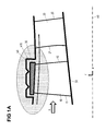
- the Figure 1A schematically shows in the meridian view, wherein x indicates the axial direction and r the radial direction, a portion of a turbomachine comprising a rotor blade row with a plurality of rotor blades 10 and a stator blade row with a plurality of stator blades 20.
- Each rotor blade 10 has a leading edge 11 and a trailing edge 12 and each stator blade 20 has a leading edge 21 and a trailing edge 22.
- the turbomachine may be a working or a fluid flow machine.
- the rotor blade row and the stator blade row are arranged in a compressor or in a turbine of a jet engine.
- the turbomachine forms a main flow path in which a fluid flows in the flow direction A.
- the main flow path is bounded radially inwardly by a hub or rotor drum 50 and radially outwardly by a housing 40.
- the hub / rotor drum 50 is rotating while the housing 40 is stationary, i. is not rotating.
- a shroud arrangement 30 shown schematically is formed at the outer blade end of the rotor blades 10. This is accommodated in a cavity 410, which is formed in the housing 40, to create the smoothest possible outer main flow path boundary.
- Also shown in the Figure 1A is the machine axis 60.
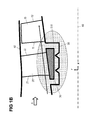
- FIG. 1B schematically shows a section of a turbomachine, which according to the turbomachine of Figure 1A is formed, wherein at the FIG. 1B However, a shroud arrangement 30 is not formed on the rotor, but on the stator. Accordingly, the shroud assembly 30 is disposed at the radially inner blade end of the stator blades 20. The shroud arrangement 30 is arranged in a cavity 510 which forms the rotating hub / rotor drum 50.
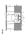
- FIG. 2A shows a corresponding section of a turbomachine, wherein a stator blade row is arranged with stator blades 20 between two rotor blade rows with rotor blades 10. Further, a fixed housing 40 and a rotating hub 50 are provided, as with respect to Fig. 1A explained. On the stator blade row, a shroud arrangement 30 is formed radially inward within a cavity 510 in the hub 50, projecting onto the sealing tips 70 of the hub 50.
- the area X of the FIG. 2A is in the FIG. 2B shown enlarged.
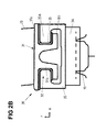
- FIG. 2B shows the shroud arrangement 30 in the plane defined by the axial direction x and the radial direction r meridian plane of the turbomachine.
- the illustration is generalized insofar as the arrangement shown is for both a rotor blade with radially outer shroud arrangement and outgoing from the housing sealing tips as well as for a stator blade with radially inner shroud arrangement and emanating from the hub or rotor drum sealing tips.
- the shroud arrangement has as main components a blade root 31 and a shroud ring 35, wherein the shroud ring 35 is positively secured to the blade root 31.
- the blade root 31 comprises a blade root platform 31a, two blade root webs 31b projecting substantially perpendicularly therefrom and blade root fingers 31c projecting from the latter in the axial direction forwards or backwards.
- two outer circumferential grooves 32 are formed, into which engage two fingers 35a of the shroud ring 35 facing each other in the axial direction.
- a wear protection sleeve 33 is provided between the mutually facing surfaces of the blade root 31 and the shroud ring 35.
- the blade root 31 and the stator blade 20 may be integrally formed.
- the shroud ring 35 has on its side facing away from the main flow path an inlet lining 36, which faces the sealing tips 70.
- the sealing tips 70 thereby form part of the hub or rotor drum and accordingly rotate relative to the static shroud arrangement 30.
- the sealing tips 70 run into the inlet lining 36 in order to prevent leakage between the hub and the stator blades minimize. If the shroud arrangement is formed on the blades of a rotor, the shroud arrangement rotates relative to a non-rotating housing with non-rotating sealing tips.
- FIG. 3 shows an embodiment of a shroud arrangement according to the invention, wherein in the FIG. 3 only the blade root of the shroud arrangement is shown and not yet the shroud.
- the connection of in the FIG. 3 described blade root with different shrouds is in the FIGS. 4 to 6 shown.
- the arrow A indicates the direction of the flow in the main flow path.
- a rotor blade row or a stator blade row with rotor blades 10 or 20, at the ends inside or outside a shroud arrangement is arranged.
- FIG. 3 is the blade profile of such a rotor blade or stator blade 10, 20 schematically indicated.
- a solid line indicates a variant in which the blade profile 10, 20 is fixedly connected to a blade root 310.
- a dotted line indicates a variant in which the blade profile 10, 20 is rotatably mounted in the blade root 310.
- the rotatable mounting via a plate 15, 25, which is formed on the blades 10, 20.
- the stator or rotor blades 10, 20 can thus be arranged rotatable or non-rotatable.
- the blade root 310 includes a blade root platform 311 which is connected to the end of the blade 10, 20 and extends at least over part of the circumference of the blade row. At the axially forward and axial rearward ends of the blade root 311, the blade root 310 forms two blade root fingers 312 (axial forward and axial rear blade root fingers) away from the main flowpath or blades 10, 20, respectively. These form on the inside mutually facing surfaces 313, 315, wherein the blade root 310 between the two blade root fingers 312 forms a recess 320 in the blade root 310.
- the blade root fingers 312 furthermore form a radial contact surface 314 on their front side facing away from the main flow path.
- the inner abutment surfaces 313, 315 each include an inclined inner abutment surface 313, which is arranged obliquely relative to the axial direction and the radial direction and faces the blades 10, 20.
- the contact surfaces 315 extend in the radial direction and are perpendicular from the front radial contact surface 314 from. Accordingly, in the illustrated embodiment, the recess 320 is dovetailed, with the recess 320 formed by the blade root fingers 312 widening in the radial direction towards the blades 10, 20 or towards the main flow path with respect to their axial extent.
- the two blade root fingers 312 are suitable for embracing an element of a shroud or a region of a shroud inserted into the recess 320 of the blade root 310 and for holding it on the blade root 310.
- the recess 320 between the blade root fingers 312 has a symmetrical shape, as well as the blade root 310 itself has a symmetrical shape.
- the abutment surfaces 313, 315 can each have a planar surface, but alternatively also have a structuring, for example for the provision of detent elements.
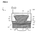
- FIG. 4 shows an embodiment of a shroud arrangement in which in the blade root 310 of the FIG. 3 a shroud 340 is inserted.
- the shroud 340 comprises a shroud ring 350 and an inlet facing 360 arranged on the side of the shroud ring 350 facing away from the main flow path, which is applied to the shroud ring 350 and consists of a comparatively soft material.
- the shroud ring 350 forms a protruding region 351, which is received in the recess 320 of the blade root 310 and held in a form-fitting manner in the blade root 310.
- the region 351 of the shroud ring 350 forms side surfaces 352 which run parallel to the inclined inner contact surfaces 313 of the blade root fingers 312, so that the region 351 of the shroud ring 350 and the recess 320 of the blade root 310 have a shape corresponding to one another.
- a wear sleeve 330 is arranged between the mutually facing contact surfaces 313, 352 of Schaufelfußfinger 312 and shroud ring 350 in the region of the blade root 312 .
- the wear protection sleeve 330 in this case has two legs 331, 332 which are formed at an angle to one another and in each case bear against the surfaces 313, 314 of the blade root fingers 312.
- the wear protection sleeve 330 serves to avoid wear and thus loosening of the connection between these components in the contact region of blade root finger 312 and shroud ring 350.
- the use of such wear sleeves 330 is optional, as with regard to FIG. 7 will be explained.
- the shroud ring 350 extends along at least a portion of the circumference of the blade row. It is advantageous if the shroud ring 350 bears against the radial abutment surfaces 314 of the blade root fingers 312 at its axially front and rear edge regions, as shown.
- the main flow path side facing away from the shroud ring 350 is substantially planar and extends in the axial direction, wherein on this side of the inlet lining 360 is arranged. Although the use of such inlet lining 360 is advantageous in many embodiments, it is not absolutely necessary.
- the shroud arrangement according to the Figures 3 and 4 are associated with the advantage that a secure connection between blade root 310 and shroud 340 can be realized even with small axial dimensions of the blade 10, 20 and thus the blade root 310, especially if the axial distance between the front and rear blade root fingers 312 is comparatively small.
- FIG. 5 shows a further embodiment of a shroud arrangement in the meridian view (xr).
- the shroud arrangement includes as well as in the FIG. 4 a blade root 310 and a shroud 340, the latter comprising a shroud ring 350 and an inlet liner 360.
- a blade root 310 and a shroud 340 the latter comprising a shroud ring 350 and an inlet liner 360.
- the shroud ring 350 does not include a closed area as in the embodiment of FIG.
- This embodiment is associated with the advantage of material and weight reduction of the shroud 350.
- FIG. 6 shows in the meridian view (xr) an embodiment of a shroud arrangement, which also comprises a blade root 310, a shroud 340 with a shroud ring 350 and an inlet lining 360 and a wear protection sleeve 330. Between the blade root fingers 312 is as in the embodiments of the FIGS. 3 to 5 a recess 320 is formed.
- the cross-sectional shape of the arranged in the recess 320 portion of the shroud ring 350 is in the embodiment of FIG. 6 designed such that the shroud ring 350 in the region of the recess 320 triangular with two V-shaped legs or webs 353, which are aligned according to the inner abutment surfaces 313 of the Schaufelfußfinger 312, and with one of the ends of the two legs or webs 353 connecting the blade root platform 311 facing base 354 is formed, wherein between the legs or webs 353 and the base 354 a material-free interior 355 remains.
- the two limbs or webs 353 do not touch each other on their side facing away from the blade root 310 and thus form an opening to the material-free inner space 355 there.
- the formation of the shroud ring 350 in the region of the recess 320 is similar here in the sectional view of the Greek letter ⁇ .
- recesses may be formed in the material of the shroud ring 350 that may face away from the main flow path or face the main flow path.
- FIGS. 7A to 7C show three embodiments of shroud arrangements, the embodiments of the FIGS. 4 . 5 and 6 correspond, but without each wear sleeves are provided. In these modified embodiments, therefore, the shroud ring 350 is in direct contact with the corresponding contact surfaces 313, 314 of the blade root fingers 312 of the blade root 310.
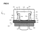
- FIG. 8 shows a further embodiment of a shroud arrangement in the meridian view (xr).
- the shroud assembly comprises a blade root 310 and a shroud 340.
- the blade root 310 has a blade root base 311 and two blade root fingers 312 extending radially away from the main flow path from the blade root base 311 and forming a recess 320 therebetween.
- the blade root fingers 312 form an axially forward blade root finger and an axial rear blade root finger and inner surfaces 316, 317, however, extending from the inner surfaces of the embodiments of FIGS FIGS. 3 to 7 differ. In each case, a radial contact surface 314 of the two blade root fingers 312 is again provided.
- the abutment surfaces on the inner sides of the blade root fingers 312 each include an inclined sliding surface 316 which adjoins the radial abutment surface 314, and an inclined inner abutment surface 317 which is formed adjacent to the blade root platform 311.
- the axial extent of the recess 320 decreases in the radial direction towards the blades, and in the area of the contact surfaces 317, the axial extent of the recess 320 broadens in the radial direction towards the blades.
- the blades themselves are in the embodiment of FIG. 8 not shown separately, but as well as in the embodiment of FIGS. 3 to 7 connected to the blade root 310.
- a latching projection 318 is formed.
- the shroud 340 comprises a shroud ring 350 and an inlet lining 360 fixed thereto.
- the shroud ring 350 forms two webs 356 extending substantially radially in the direction of the blades and the main flow path, respectively their respective end form a protruding and the adjacent contact surface 317 facing latch 357.
- the detent 357 engages with the latching projection 318 of the blade root 310 when the webs 356 are inserted into the recess 320.
- the webs 356 form an integral part of the shroud ring 350. It can be provided that the shroud ring 350 is interrupted several times in the region of the webs 356 on the circumference, so that the webs 356 can act structurally elastic and yield according to pressure. It can be provided that the number the discontinuities of the two webs 356 coincide at the periphery with the number of blades or blade feet or forms a multiple thereof.
- FIG. 9 shows an embodiment which, except for the circumstance of the embodiment of the FIG. 5 corresponds that the shroud ring 350 'additionally assumes the function of the inlet lining, so that shroud ring and inlet lining are combined to form a single integral component 350'.
- the integral inlet cover band ring 350 is produced by means of an injection molding or sintering process.
- the embodiment of the FIG. 9 apart from the use of a wear sleeve. However, such may alternatively be provided.
- the blade root can also form a recess in another way than described herein, into which a region or a component or an element of a shroud for connecting the blade root and shroud is inserted and held.
Landscapes
- Engineering & Computer Science (AREA)
- Mechanical Engineering (AREA)
- General Engineering & Computer Science (AREA)
- Structures Of Non-Positive Displacement Pumps (AREA)
- Turbine Rotor Nozzle Sealing (AREA)
Abstract
Die Erfindung betrifft eine Deckbandanordnung für eine Strömungsmaschine, die aufweist: mindestens einen Schaufelfuß (310), der dazu ausgebildet ist, mit mindestens einem einer Reihe von Schaufeln (10, 20) eines Rotors oder eines Stators einer Strömungsmaschine verbunden zu werden, oder der mit mindestens einem solchen verbunden ist; und ein Deckband (340, 350, 360), dass an der den Schaufeln (10, 20) abgewandten Seite des Schaufelfußes (310) mit diesem verbunden ist. Es ist vorgesehen, dass der Schaufelfuß (310) an der den Schaufeln (10, 20) abgewandten Seite zwei sich im Wesentlichen in radialer Richtung erstreckende und zueinander axial beabstandete Schaufelfu ßfinger (312) aufweist, die zwischen sich eine in Umfangsrichtung durchgehende Ausnehmung (320) ausbilden, und mindestens ein Element oder Bereich (353) des Deckbandes (340, 350, 360) zur Befestigung am Schaufelfuß (310) in der Ausnehmung (320) angeordnet ist. Dazu ist weiter vorgesehen, dass das Deckband (350) zwei Stege (353) aufweist, die sich in die Ausnehmung (320) erstrecken und die von den Schaufelfußfingern (312) umfasst werden, wobei die zwei Stege (353) im Wesentlichen eine V-förmige Anordnung bilden.The invention relates to a shroud arrangement for a turbomachine, comprising: at least one blade root (310), which is adapted to be connected to at least one of a row of blades (10, 20) of a rotor or a stator of a turbomachine, or with connected to at least one such; and a shroud (340, 350, 360) that is connected to the blade (10, 20) side facing away from the blade root (310) with this. It is provided that on the side facing away from the blades (10, 20), the blade root (310) has two blade fingers (312) which extend substantially in the radial direction and are axially spaced from one another and which have a circumferential recess (320) between them ), and at least one element or region (353) of the shroud (340, 350, 360) for attachment to the blade root (310) in the recess (320) is arranged. For this purpose, it is further provided that the shroud (350) has two webs (353) which extend into the recess (320) and which are encompassed by the blade root fingers (312), wherein the two webs (353) essentially have a V axis. form a shaped arrangement.
Description
Die Erfindung betrifft eine Deckbandanordnung für eine Strömungsmaschine gemäß dem Oberbegriff des Anspruchs 1.The invention relates to a shroud arrangement for a turbomachine according to the preamble of claim 1.
Die aerodynamische Belastbarkeit und die Effizienz von Strömungsmaschinen, im Besonderen von Strömungsarbeitsmaschinen wie Bläsern, Verdichtern, Pumpen und Ventilatoren wird durch unter anderem durch Leckageströme an den Rändern des Hauptströmungspfades begrenzt. Dabei besteht eine Quelle solcher in Strömungsmaschinen entstehender Verluste in der Leckageströmung um Schaufeldeckbänder. Diese treten häufig am inneren Schaufelende von Statoren oder am äußeren Schaufelende von Rotoren auf.The aerodynamic load capacity and the efficiency of turbomachines, in particular of fluid flow machines such as fans, compressors, pumps and fans is limited by, among other things, leakage flows at the edges of the main flow path. There is a source of such resulting in turbomachinery losses in the leakage flow to Schaufeldeckbänder. These often occur at the inner blade end of stators or at the outer blade end of rotors.
Eine solche Leckageströmung wird üblicherweise durch Dichtspitzen, die innerhalb einer Kavität, in die das Deckband eingebettet ist, angeordnet sind, klein gehalten. Eine derartige Anordnung ist beispielsweise aus der
Aus der
Der vorliegenden Erfindung liegt die Aufgabe zu Grunde, eine Deckbandanordnung für eine Schaufelreihe eines Rotors oder Stators einer Strömungsmaschine bereitzustellen, die auch auf axial engem Raum realisiert werden kann.The present invention is based on the object to provide a shroud arrangement for a row of blades of a rotor or stator of a turbomachine, which can be realized even in an axially small space.
Diese Aufgabe wird erfindungsgemäß durch eine Deckbandanordnung mit den Merkmalen des Anspruchs 1 und eine Schaufelreihe mit den Merkmalen des Anspruchs 15 gelöst. Ausgestaltungen der Erfindung sind in den Unteransprüchen angegeben.This object is achieved by a shroud arrangement with the features of claim 1 and a blade row with the features of
Danach geht die Erfindung von einer Deckbandanordnung für eine Strömungsmaschine aus, die mindestens einen Schaufelfuß und ein Deckband aufweist. Der Schaufelfuß ist dazu ausgebildet, mit mindestens einem Schaufelende einer Reihe von Schaufeln eines Rotors oder eines Stators einer Strömungsmaschine verbunden zu werden, oder ist mit mindestens einem solchen Schaufelende verbunden. Das Deckband ist an der den Schaufeln abgewandten Seite des Schaufelfußes mit diesem verbunden. Erfindungsgemäß ist vorgesehen, dass der Schaufelfuß an der den Schaufeln abgewandten Seite (d.h. an der vom Hauptströmungspfad der Strömungsmaschine weg weisenden Seite) zwei sich im Wesentlichen in radialer Richtung erstreckende und zueinander axial beabstandete Schaufelfußfinger aufweist. Die Schaufelfußfinger bilden zwischen sich eine in Umfangsrichtung durchgehende Ausnehmung aus. Dabei ist mindestens ein Element oder mindestens ein Bereich des Deckbandes zur Befestigung am Schaufelfuß in der Ausnehmung angeordnet. Hierbei handelt es sich erfindungsgemäß und zwei Stege, die sich in die Ausnehmung erstrecken und die von den Schaufelfußfingern umfasst werden, wobei die zwei Stege im Wesentlichen eine V-förmige Anordnung bilden. Die zwei Stege korrespondieren dabei mit entsprechenden Anlageflächen der Schaufelfußfinger und sind formschlüssig in der Ausnehmung gehalten. Die zwei Stege sind in axialer Richtung beabstandet.Thereafter, the invention of a shroud arrangement for a turbomachine, which has at least one blade root and a shroud. The blade root is adapted to be connected to at least one blade end of a row of blades of a rotor or a stator of a turbomachine, or is connected to at least one such blade end. The shroud is connected at the side facing away from the blades of the blade root with this. According to the invention, the blade root on the side facing away from the blades (i.e., on the side facing away from the main flow path of the turbomachine) has two blade root fingers extending substantially in the radial direction and axially spaced from each other. The Schaufelfußfinger form between them a circumferentially continuous recess. In this case, at least one element or at least a portion of the shroud is arranged for attachment to the blade root in the recess. These are according to the invention and two webs which extend into the recess and which are encompassed by the blade root fingers, wherein the two webs form a substantially V-shaped arrangement. The two webs correspond with corresponding contact surfaces of the Schaufelfußfinger and are positively held in the recess. The two webs are spaced in the axial direction.
Die erfindungsgemäße Lösung beruht somit auf dem Gedanken, in einem Schaufelfuß zwischen zwei axial beabstandeten Schaufelfußfingern eine Ausnehmung bereitzustellen, die der Aufnahme und Befestigung eines Deckbandes dient. Dabei kann die erfindungsgemäße Deckbandanordnung auch auf axial engem Raum realisiert werden, indem ein kleiner axialer Abstand der Schaufelfußfinger gewählt wird. Dies schränkt die Möglichkeiten der Befestigung eines Deckbandes nicht ein, da das mindestens eine Element oder der mindestens eine Bereich des Deckbandes, das/der in die zwischen den Schaufelfußfinger definierte Ausnehmung eingebracht wird, in seiner axialen Ausdehnung ebenfalls entsprechend klein ausgebildet werden kann.The solution according to the invention is thus based on the idea of providing a recess in a blade root between two axially spaced blade root fingers, which serves to receive and fasten a shroud. In this case, the shroud arrangement according to the invention can also be realized in an axially small space by a small axial distance of the Schaufelfußfinger is selected. This does not limit the possibilities of fastening a shroud, since the at least one element or the at least one region of the shroud, which is introduced into the recess defined between the blade root fingers, can also be made correspondingly small in its axial extent.
Die erfindungsgemäße Lösung ist mit dem Vorteil verbunden, dass durch die zwei Stege und deren V-förmige Anordnung eine Elastizität bereitgestellt wird, die es ermöglicht, Fertigungstoleranzen auszugleichen, so dass das Deckband ohne Spiel in der Ausnehmung des Schaufelfußes angeordnet ist.The solution according to the invention has the advantage that an elasticity is provided by the two webs and their V-shaped arrangement, which makes it possible to compensate for manufacturing tolerances, so that the shroud is arranged without play in the recess of the blade root.
In einer Ausgestaltung der Erfindung ist vorgesehen, dass die durch die Schaufelfußfinger gebildete Ausnehmung eine konkave Form aufweist. Beispielsweise ist die Ausnehmung hierzu zumindest in einem Teilbereich schwalbenschwanzförmig ausgebildet, wobei sie sich in Richtung der Schaufeln verbreitert. Die zwei Stege sind formschlüssig in der Ausnehmung angeordnet, wobei jeweils ein Steg an einer korrespondierenden Anlagefläche eines Schaufelfußfingers anliegt. Insbesondere verlaufen die V-förmig angeordneten Stege jeweils parallel zu einer inneren Anlagefläche einer der Schaufelfußfinger.In one embodiment of the invention it is provided that the recess formed by the Schaufelfußfinger has a concave shape. For example, the recess is designed to be dovetail-shaped at least in a partial region, widening in the direction of the blades. The two webs are positively arranged in the recess, wherein in each case a web rests against a corresponding contact surface of a Schaufelfußfingers. In particular, the V-shaped webs each extend parallel to an inner contact surface of one of the blade root fingers.
Gemäß einer weiteren Ausgestaltung der Erfindung bildet jeder Schaufelfußfinger mindestens eine innere Anlagefläche aus, die der inneren Anlagefläche des jeweils anderen Schaufelfußfingers zumindest teilweise zugewandt ist. Dabei kann vorgesehen sein, dass mindestens eine der inneren Anlageflächen schräg zur Radialrichtung und zur Axialrichtung angeordnet und dabei den Schaufeln zugewandt ist. Die schrägen inneren Anlageflächen führen dazu, dass die durch die Schaufelfußfinger gebildete Ausnehmung sich zumindest abschnittsweise in radialer Richtung zu den Schaufeln hin im Hinblick auf ihre axiale Ausdehnung verbreitert, wodurch ein Element oder Bereich des Deckbandes sicher in der Ausnehmung gehalten werden kann. Weiter kann vorgesehen sein, dass wenigstens eine der beiden inneren Anlageflächen über einen Bereich ebenflächig ausgebildet ist.According to a further embodiment of the invention, each blade root finger forms at least one inner contact surface which at least partially faces the inner contact surface of the respective other blade root finger. It can be provided that at least one of the inner bearing surfaces is arranged obliquely to the radial direction and the axial direction and thereby faces the blades. The oblique inner abutment surfaces cause the recess formed by the Schaufelfußfinger widened at least in sections in the radial direction to the blades with respect to their axial extent, whereby an element or region of the shroud can be securely held in the recess. It can further be provided that at least one of the two inner contact surfaces is planar over an area.
Gemäß einer weiteren Ausgestaltung der Erfindung weist mindestens einer der Schaufelfußfinger Rastmittel zur Verrastung mit einem Element oder Bereich des Deckbandes auf. Eine solche Verrastung sichert die Verbindung zwischen Schaufelfuß und Deckband.According to a further embodiment of the invention, at least one of the Schaufelfußfinger locking means for locking with an element or region of the shroud on. Such locking secures the connection between the blade root and shroud.
Es kann weiter vorgesehen sein, dass der Deckbandring im Bereich der Stege am Umfang mehrmals unterbrochen ist, so dass die Stege in verstärktem Maße elastisch ausgebildet sind. Beispielsweise stimmt die Anzahl der Unterbrechungen der beiden Stege am Umfang mit der Anzahl der Schaufeln überein oder bildet ein Vielfaches davon. Auch können die genannten Stege im Kontaktbereich mit dem Schaufelfuß eine Rastnase aufweisen, zwecks einer rastenden formschlüssigen Verbindung mit den Schaufelfußfingern im Bereich der Ausnehmung.It may further be provided that the shroud ring is interrupted several times in the area of the webs on the circumference, so that the webs are formed to an increased extent elastic. For example, the number of interruptions of the two webs on the circumference coincides with the number of blades or forms a multiple thereof. The webs mentioned can also have a latching nose in the area of contact with the blade root, for the purpose of a latching positively locking connection with the blade root fingers in the region of the recess.
Die erfindungsgemäße Deckbandanordnung ist bevorzugt dazu vorgesehen, im Fall ihrer Verbindung mit einer Rotorschaufelreihe mit von einem radial außen angrenzenden Gehäuse ausgehenden Dichtspitzen und im Fall ihrer Verbindung mit einer Statorschaufelreihe mit Dichtspitzen einer radial innen liegenden Nabe oder Rotortrommel zusammenzuwirken.The shroud arrangement according to the invention is preferably provided, in the case of its connection to a rotor blade row, with a radially outwardly adjacent one Casing outgoing sealing tips and in the case of their connection with a stator blade row with sealing tips of a radially inner hub or rotor drum cooperate.
In einer weiteren Ausgestaltung der Erfindung weist das Deckband einen Deckbandring auf, der in der Ausnehmung des Schaufelfußes angeordnet ist und der sich entlang wenigstens eines Teils des Umfangs der Schaufelreihe erstreckt. Der Deckbandring erstreckt sich somit beispielsweise entlang des gesamten Umfangs der Schaufelreihe oder entlang eines Teils des Umfangs der Schaufelreihe.In a further embodiment of the invention, the shroud has a shroud ring, which is arranged in the recess of the blade root and which extends along at least part of the circumference of the blade row. The shroud ring thus extends, for example, along the entire circumference of the blade row or along part of the circumference of the blade row.
Gemäß einer Ausführungsvariante ist an der dem Schaufelfuß abgewandten Seite des Deckbandringes ein Einlaufbelag am Deckbandring angeordnet. Dieser besteht üblicherweise aus einem weicheren Material als der Deckbandring und dient dazu, dass Dichtspitzen eines angrenzenden Gehäuse oder einer angrenzenden Nabe sich in diesen einarbeiten können, um eine vorhandene Leckageströmung zu minimieren. Alternativ kann vorgesehen sein, dass die Funktion des Deckbandringes und die Funktion des Einlaufbelages durch ein Bauteil bereitgestellt wird, also Deckbandring und Einlaufbelag durch ein Bauteil realisiert werden.According to one embodiment variant, an inlet lining is arranged on the shroud ring on the side of the shroud ring facing away from the blade root. This is usually made of a softer material than the shroud ring and serves to ensure that the sealing tips of an adjacent housing or an adjacent hub can work into this, in order to minimize an existing leakage flow. Alternatively it can be provided that the function of the shroud ring and the function of the inlet lining is provided by a component, so shroud and inlet lining are realized by a component.
Üblicherweise ist vorgesehen, dass in der Strömungsmaschine, in der die erfindungsgemäße Deckbandanordnung angeordnet ist, die den Schaufeln von Rotor oder Stator zugewandte Seite des Schaufelfußes den Hauptströmungspfad berandet. Dabei ist die den Schaufeln abgewandte Seite des Schaufelfußes in einer Kavität der angrenzenden strömungsbegrenzenden Struktur (Gehäuse oder Nabe/Rotortrommel) angeordnet. Grundsätzlich sind aber auch davon abweichende Ausgestaltungen möglich.It is usually provided that in the turbomachine in which the shroud arrangement according to the invention is arranged, the side of the blade root facing the blades of the rotor or stator edges over the main flow path. In this case, the side of the blade root facing away from the blades is arranged in a cavity of the adjacent flow-limiting structure (housing or hub / rotor drum). In principle, however, deviating configurations are also possible.
In einer Ausgestaltung der Erfindung weist wenigstens einer der Schaufelfußfinger an seinem Ende eine den Schaufeln abgewandte radiale Anlagefläche auf. An dieser liegt ebenfalls das Deckband oder, sofern eingesetzt, eine Verschleißschutzhülse an. Insbesondere kann vorgesehen sein, dass das Deckband in mindestens einem seiner axial vorderen und hinteren Randbereiche an einer radialen Anlagefläche eines Schaufelfußfingers anliegt.In one embodiment of the invention, at least one of the Schaufelfußfinger at its end facing away from the blades radial contact surface. At this is also the shroud or, if used, a wear sleeve. In particular, it can be provided that the shroud rests in at least one of its axially front and rear edge regions on a radial contact surface of a Schaufelfußfingers.
In einer weiteren Ausgestaltung der Erfindung besitzt die Ausnehmung zwischen den Schaufelfußfingern eine symmetrische Form. Für diesen Fall sind auch die Schaufelfußfinger symmetrisch am Schaufelfuß angeordnet.In a further embodiment of the invention, the recess between the Schaufelfußfingern has a symmetrical shape. For this case, the blade root fingers are arranged symmetrically on the blade root.
Es kann bei der erfindungsgemäßen Deckbandanordnung wenigstens eine Verschleißschutzhülse eingesetzt werden, die zwischen aneinander angrenzenden Flächen des Schaufelfußes und des Deckbandringes angeordnet ist. Eine solche Verschleißschutzhülse vermindert die Gefahr eines Verschleißes von Schaufelfuß und Deckband an ihren aneinander angrenzenden Flächen und damit die Gefahr einer Lockerung der Verbindung von Schaufelfuß und Deckband. Jedoch kann alternativ ebenfalls vorgesehen sein, keine Verschleißschutzhülse einzusetzen, so dass der Deckbandring an den radialen und/oder inneren Anlageflächen in direktem Kontakt mit dem Schaufelfuß steht.It can be used in the shroud arrangement according to the invention at least one wear protection sleeve, which is arranged between adjacent surfaces of the blade root and the shroud ring. Such a wear sleeve reduces the risk of wear of the blade root and shroud on their adjacent surfaces and thus the risk of loosening the connection of the blade root and shroud. However, alternatively it can also be provided to use no wear protection sleeve, so that the shroud ring is in direct contact with the blade root on the radial and / or inner abutment surfaces.
Eine weitere Ausgestaltung der Erfindung sieht vor, dass der Deckbandring in seinem den Schaufeln zugewandten Abschnitt von den Schaufelfußfingern umfasst wird und einen der Ausnehmung im Schaufelfuß ähnlichen Querschnittsumriss besitzt.A further embodiment of the invention provides that the shroud ring is comprised in its blade facing portion of the blade root fingers and has a cross-sectional contour similar to the recess in the blade root.
Der Querschnitt des Deckbandringes kann in einer Ausgestaltung der Erfindung eine in Umfangsrichtung durchgehende Ausnehmung aufweisen. Es kann vorgesehen sein, dass eine solche Ausnehmung im Deckbandring von der dem Hauptströmungspfad zugewandten Seite oder von der dem Hauptströmungspfad abgewandten Seite eingebracht ist. Die Ausnehmung kann Strukturen des Deckbandes definieren, die in der Ausnehmung des Schaufelfußes angeordnet sind.The cross-section of the shroud ring can have a circumferentially continuous recess in one embodiment of the invention. It can be provided that such a recess in the shroud ring is introduced from the side facing the main flow path or from the side facing away from the main flow path. The recess may define structures of the shroud, which are arranged in the recess of the blade root.
Eine Ausgestaltung der Erfindung sieht vor, dass die zwei V-förmig angeordneten Stege an ihren in die Ausnehmung des Schaufelfußes ragenden Enden durch eine dem Schaufelfuß zugewandte Basis miteinander verbunden sind, wobei zwischen den Stegen und der Basis ein materialfreier Innenraum verbleibt. Insgesamt entsteht dabei eine im Schnitt dreieckförmige Anordnung. Dabei kann vorgesehen sein, dass die Anordnung der zwei Stege und der Basis in der Schnittdarstellung näherungsweise entsprechend dem griechischen Buchstaben Omega ausgebildet ist. Durch Bereitstellen eines materialfreien Innenraums wird trotz der Verbindung der beiden Stege durch eine Basis eine Elastizität der Gesamtanordnung bereitgestellt, die es erlaubt, eventuell vorhandene Fertigungstoleranzen bzw. ein durch diese verursachten Spiel auszugleichen.An embodiment of the invention provides that the two V-shaped webs are connected at their projecting into the recess of the blade root ends by a blade root facing base with each other, wherein between the webs and the base remains a material-free interior. Overall, this creates an average triangular arrangement. It can be provided that the arrangement of the two webs and the base in the sectional view is approximately formed according to the Greek letter omega. By providing a material-free interior, despite the connection of the two webs by a base, an elasticity of the overall arrangement is provided, which makes it possible to compensate for any manufacturing tolerances or a game caused by them.
Gemäß einer Ausführungsvariante der Erfindung bildet das Deckband bzw. der Deckbandring in Richtung der Schaufeln im Querschnitt der Meridianebene einen dreieckförmigen Vorsprung, der in der Ausnehmung angeordnet ist. Zwei Schenkel des dreieckförmigen Vorsprungs, die durch die zwei V-förmig angeordneten Stege gebildet sind, liegen dabei an entsprechenden inneren schrägen Anlageflächen der Schaufelfußfinger an. Dabei kann vorgesehen sein, dass der dreieckförmige Vorsprung zumindest näherungsweise die Form des griechischen Buchstabens Ω besitzt und sich dementsprechend die beiden Schenkel des dreieckförmigen Vorsprungs an der dem Hauptströmungspfad abgewandten Seite nicht berühren, vielmehr der dreieckförmige Vorsprung an der dem Hauptströmungspfad abgewandten Seite eine Ausnehmung aufweist.According to one embodiment of the invention, the shroud or the shroud ring forms in the direction of the blades in the cross section of the meridian plane a triangular projection which is arranged in the recess. Two legs of the triangular projection, which are formed by the two V-shaped webs, lie on corresponding inner inclined contact surfaces of the Blade on foot. It can be provided that the triangular projection has at least approximately the shape of the Greek letter Ω and accordingly the two legs of the triangular projection on the side facing away from the main flow path do not touch, but the triangular projection on the side facing away from the main flow path has a recess.
Die vorliegende Erfindung bezieht sich allgemein auf Schaufelreihen für Strömungsmaschinen wie Turbinen, und im besonderen Strömungsarbeitsmaschinen wie Bläser, Verdichter, Pumpen und Ventilatoren in axialer oder halbaxialer Bauart. Das Arbeitsmedium oder Fluid kann gasförmig oder flüssig sein. Die Strömungsmaschine kann eine oder mehrere Stufen mit jeweils einem Rotor und einem Stator umfassen. In Einzelfällen wird die Stufe lediglich durch einen Rotor gebildet.The present invention relates generally to blade rows for turbomachines such as turbines, and more particularly to fluid flow machines such as fans, compressors, pumps and fans in the axial or semi-axial design. The working medium or fluid may be gaseous or liquid. The turbomachine may include one or more stages each having a rotor and a stator. In some cases, the stage is formed only by a rotor.
Der Rotor einer Strömungsmaschine, in der eine erfindungsgemäße Deckbandanordnung eingesetzt wird, besteht aus einer Anzahl von Schaufeln, die mit der rotierenden Welle der Strömungsmaschine verbunden sind. Der Stator einer Strömungsmaschine, in der eine erfindungsgemäße Deckbandanordnung eingesetzt wird, besteht aus einer Anzahl feststehender Schaufeln. Die Rotortrommel und die Beschaufelung sind üblicherweise von einem Gehäuse umgeben.The rotor of a turbomachine, in which a shroud arrangement according to the invention is used, consists of a number of blades, which are connected to the rotating shaft of the turbomachine. The stator of a turbomachine, in which a shroud arrangement according to the invention is used, consists of a number of fixed blades. The rotor drum and the blading are usually surrounded by a housing.
Eine Strömungsmaschine, in der eine erfindungsgemäße Deckbandanordnung eingesetzt wird, kann auch einen Stator vor dem ersten Rotor, ein sogenanntes Vorleitrad, aufweisen. Mindestens ein Stator oder Vorleitrad kann - abweichend von einer unbeweglichen Fixierung - drehbar gelagert sein, um den Anstellwinkel verändern zu können. Eine Verstellung erfolgt beispielsweise durch eine von außerhalb des Ringkanals zugängliche Spindel.A turbomachine, in which a shroud arrangement according to the invention is used, can also have a stator in front of the first rotor, a so-called leading wheel. At least one stator or Vorleitrad - may be rotatably mounted - deviating from an immovable fixation - to change the angle of attack can. An adjustment is made for example by a spindle accessible from outside the annular channel.
In einer Ausgestaltung kann eine Strömungsmaschine, in der eine erfindungsgemäße Deckbandanordnung eingesetzt wird, mindestens eine Reihe verstellbarer Rotoren aufweisen.In one embodiment, a turbomachine, in which a shroud arrangement according to the invention is used, have at least one row of adjustable rotors.
In einer Ausgestaltung kann eine Strömungsmaschine, in der eine erfindungsgemäße Deckbandanordnung eingesetzt wird, bei Mehrstufigkeit zwei gegenläufige Wellen besitzen, so daß die Rotorschaufelreihen von Stufe zu Stufe die Drehrichtung wechseln. Hierbei existieren keine Statoren zwischen aufeinander folgenden Rotoren.In one embodiment, a turbomachine in which a shroud arrangement according to the invention is used in multi-stage have two opposing shafts, so that the rotor blade rows change the direction of rotation from stage to stage. There are no stators between successive rotors.
In einer Ausgestaltung kann eine Strömungsmaschine, in der eine erfindungsgemäße Deckbandanordnung eingesetzt wird, eine Nebenstromkonfiguration derart aufweisen, daß sich ein einstromiger Ringkanal hinter einer bestimmten Schaufelreihe in zwei konzentrische Ringkanäle aufteilt, die ihrerseits mindestens jeweils eine weitere Schaufelreihe beherbergen.In one embodiment, a turbomachine, in which a shroud arrangement according to the invention is used, have a bypass configuration such that a single-flow annular channel divides behind a certain row of blades into two concentric annular channels, which in turn each accommodate at least one further row of blades.
Die Erfindung betrifft des Weiteren eine Schaufelreihe einer Strömungsmaschine mit einer erfindungsgemäßen Deckbandanordnung.The invention further relates to a blade row of a turbomachine with a shroud arrangement according to the invention.
Die Erfindung wird nachfolgend unter Bezugnahme auf die Figuren der Zeichnung anhand mehrerer Ausführungsbeispiele näher erläutert. Es zeigen:
- Fig. 1A
- schematisch einen Rotor mit einem Deckband;
- Fig. 1B
- schematisch einen Stator mit einem Deckband;
- Fig. 2A
- ein Beispiel einer Deckbandanordnung gemäß dem Stand der Technik;
- Fig. 2B
- eine vergrößerte Darstellung des Bereichs X des Beispiels der
Fig. 2A ; - Fig. 3
- ein erstes Ausführungsbeispiel eines Schaufelfußes einer Deckbandanordnung;
- Fig. 4
- ein erstes Ausführungsbeispiel einer Deckbandanordnung unter Verwendung des Schaufelfußes der
Fig. 3 und eines ersten Ausführungsbeispiels eines Deckbandes; - Fig.5
- ein zweites Ausführungsbeispiel einer Deckbandanordnung unter Verwendung des Schaufelfußes der
Fig. 3 und eines zweiten Ausführungsbeispiels eines Deckbandes; - Fig. 6
- ein drittes Ausführungsbeispiel einer Deckbandanordnung unter Verwendung des Schaufelfußes der
Fig. 3 und eines dritten Ausführungsbeispiels eines Deckbandes; - Fig. 7a-c
- Deckbandanordnungen gemäß den
Figuren 4 bis 6 , die jedoch jeweils ohne eine Verschleißschutzhülse ausgebildet sind; - Fig. 8
- ein weiteres Ausführungsbeispiel einer Deckbandanordnung; und
- Fig. 9
- ein Ausführungsbeispiel einer Deckbandanordnung, bei der ein Deckbandring und ein Einlaufbelag des Deckbandes einteilig ausgebildet sind.
- Fig. 1A
- schematically a rotor with a shroud;
- Fig. 1B
- schematically a stator with a shroud;
- Fig. 2A
- an example of a shroud arrangement according to the prior art;
- Fig. 2B
- an enlarged view of the area X of the example of
Fig. 2A ; - Fig. 3
- a first embodiment of a blade root of a shroud arrangement;
- Fig. 4
- a first embodiment of a shroud arrangement using the blade root of the
Fig. 3 and a first embodiment of a shroud; - Figure 5
- A second embodiment of a shroud arrangement using the blade root of the
Fig. 3 and a second embodiment of a shroud; - Fig. 6
- a third embodiment of a shroud arrangement using the blade root of the
Fig. 3 and a third embodiment of a shroud; - Fig. 7a-c
- Shroud arrangements according to
FIGS. 4 to 6 , however, each formed without a wear sleeve; - Fig. 8
- a further embodiment of a shroud arrangement; and
- Fig. 9
- An embodiment of a shroud arrangement, in which a shroud ring and an inlet lining of the shroud are integrally formed.
Die
Die Strömungsmaschine bildet einen Hauptströmungspfad aus, in dem ein Fluid in der Strömungsrichtung A strömt. Der Hauptströmungspfad wird radial innen durch eine Nabe oder Rotortrommel 50 und radial außen durch ein Gehäuse 40 begrenzt. Die Nabe/Rotortrommel 50 ist dabei rotierend ausgebildet, während das Gehäuse 40 stehend, d.h. nicht rotierend ausgebildet ist.The turbomachine forms a main flow path in which a fluid flows in the flow direction A. The main flow path is bounded radially inwardly by a hub or
Am äußeren Schaufelende der Rotorschaufeln 10 ist eine schematisch dargestellte Deckbandanordnung 30 ausgebildet. Diese ist in einer Kavität 410, die im Gehäuse 40 ausgebildet ist, zur Schaffung einer möglichst glatten äußeren Hauptströmungspfadbegrenzung aufgenommen.At the outer blade end of the
Ebenfalls dargestellt in der
Zum besseren Verständnis der vorliegenden Erfindung wird im Folgenden anhand der
Die
Die Deckbandanordnung weist als Hauptkomponenten einen Schaufelfuß 31 und einen Deckbandring 35 auf, wobei der Deckbandring 35 formschlüssig am Schaufelfuß 31 befestigt ist. Der Schaufelfuß 31 umfasst eine Schaufelfußplattform 31a, zwei davon im Wesentlichen senkrecht abstehende Schaufelfußstege 31b und von letzteren in axialer Richtung nach vorne bzw. nach hinten abstehende Schaufelfußfinger 31c auf. Dabei werden zwischen den Schaufelfußfingern 31c und der Schaufelfußplattform 31a zwei äußere Umfangsnuten 32 gebildet, in die zwei in axialer Richtung aufeinander zu weisende Finger 35a des Deckbandrings 35 eingreifen. Weiter kann vorgesehen sein, dass wie dargestellt zwischen den einander zugewandten Oberflächen von Schaufelfuß 31 und Deckbandring 35 eine Verschleißschutzhülse 33 vorgesehen ist.The shroud arrangement has as main components a
Der Schaufelfuß 31 und die Statorschaufel 20 können einteilig ausgebildet sein.The
Der Deckbandring 35 weist an seiner dem Hauptströmungspfad abgewandten Seite einen Einlaufbelag 36 auf, der den Dichtspitzen 70 zugewandt ist. Die Dichtspitzen 70 bilden dabei einen Teil der Nabe oder Rotortrommel und rotieren dementsprechend relativ zu der statischen Deckbandanordnung 30. Dabei laufen die Dichtspitzen 70 in den Einlaufbelag 36 ein, um eine Leckage zwischen Nabe und Statorschaufeln zu minimieren. Sofern die Deckbandanordnung an den Schaufeln eines Rotors ausgebildet ist, rotiert die Deckbandanordnung relativ zu einem nicht-rotierenden Gehäuse mit nicht-rotierenden Dichtspitzen.The
Die
Der Pfeil A kennzeichnet die Richtung der Strömung im Hauptströmungspfad. Wie in Bezug auf die
Dabei sind in der
Der Schaufelfuß 310 umfasst eine Schaufelfußplattform 311, die mit dem Ende der Schaufel 10, 20 verbunden ist und sich zumindest über einen Teil des Umfangs der Schaufelreihe erstreckt. Am axial vorderen und am axial hinteren Ende der Schaufelfußplattform 311 bildet der Schaufelfuß 310 zwei vom Hauptströmungspfad bzw. den Schaufeln 10, 20 weg weisende Schaufelfußfinger 312 aus (einen axial vorderen und einen axial hinteren Schaufelfußfinger). Diese bilden innenseitig einander zugewandte Flächen 313, 315 aus, wobei der Schaufelfuß 310 zwischen den beiden Schaufelfußfingern 312 eine Ausnehmung 320 im Schaufelfuß 310 bildet.The
Die Schaufelfußfinger 312 bilden des Weiteren an ihrer dem Hauptströmungspfad abgewandten Stirnseite eine radiale Anlagefläche 314 aus.The
Die inneren Anlagenflächen 313, 315 umfassen jeweils eine schräg verlaufende innere Anlagefläche 313, die gegenüber der Axialrichtung und der Radialrichtung schräg angeordnet und den Schaufeln 10, 20 zugewandt ist. Die Anlageflächen 315 verlaufen in radialer Richtung und stehen senkrecht von der vorderen radialen Anlagefläche 314 ab. Dementsprechend ist die Aussparung 320 im dargestellten Ausführungsbeispiel schwalbenschwanzartig ausgeführt, wobei die durch die Schaufelfußfinger 312 gebildete Ausnehmung 320 sich in radialer Richtung zu den Schaufeln 10, 20 bzw. zum Hauptströmungspfad hin im Hinblick auf ihre axiale Ausdehnung verbreitert.The inner abutment surfaces 313, 315 each include an inclined
Die beiden Schaufelfußfinger 312 sind dazu geeignet, ein in die Ausnehmung 320 des Schaufelfußes 310 eingesetztes Element eines Deckbandes oder einen Bereich eines Deckbandes zu umgreifen und am Schaufelfuß 310 zu halten.The two
Die Ausnehmung 320 zwischen den Schaufelfußfingern 312 besitzt eine symmetrische Form, wie auch der Schaufelfuß 310 selbst eine symmetrische Form besitzt. Die Anlageflächen 313, 315 können jeweils ebenflächig ausgebildet sein, alternativ jedoch auch eine Strukturierung, beispielsweise zur Bereitstellung von Rastelementen aufweisen.The
Die
Der Deckbandring 350 bildet einen vorstehenden Bereich 351 aus, der in der Ausnehmung 320 des Schaufelfußes 310 aufgenommen und formschlüssig im Schaufelfuß 310 gehalten wird. Dabei bildet der Bereich 351 des Deckbandringes 350 Seitenflächen 352 aus, die parallel zu den schräg verlaufenden inneren Anlageflächen 313 der Schaufelfußfinger 312 verlaufen, so dass der Bereich 351 des Deckbandringes 350 und die Ausnehmung 320 des Schaufelfußes 310 eine zueinander korrespondierende Form besitzen.The
Des Weiteren ist vorgesehen, dass zwischen den einander zugewandten Anlageflächen 313, 352 von Schaufelfußfinger 312 und Deckbandring 350 im Bereich der Schaufelfußfinger 312 eine Verschleißschutzhülse 330 angeordnet ist. Die Verschleißschutzhülse 330 weist dabei zwei winklig zueinander ausgebildete Schenkel 331, 332 auf, die jeweils an den Flächen 313, 314 der Schaufelfußfinger 312 anliegen. Die Verschleißschutzhülse 330 dient dazu, im Kontaktbereich von Schaufelfußfinger 312 und Deckbandring 350 einen Verschleiß und damit eine Lockerung der Verbindung zwischen diesen Bauteilen zu vermeiden. Die Verwendung solcher Verschleißschutzhülsen 330 ist jedoch optional, wie im Hinblick auf die
Der Deckbandring 350 verläuft entlang wenigstens eines Teils des Umfangs der Schaufelreihe. Es ist von Vorteil, wenn der Deckbandring 350 an seinen axial vorderen und hinteren Randbereichen wie dargestellt an den radialen Anlageflächen 314 der Schaufelfußfinger 312 anliegt. Die dem Hauptströmungspfad abgewandte Seite des Deckbandringes 350 ist im Wesentlichen eben und verläuft in Axialrichtung, wobei an dieser Seite der Einlaufbelag 360 angeordnet ist. Dabei ist die Verwendung eines solchen Einlaufbelages 360 zwar in vielen Ausführungsvarianten vorteilhaft, jedoch nicht zwingend erforderlich.The
Die Deckbandanordnung gemäß den
Die
Dieses Ausführungsbeispiel ist mit dem Vorteil einer Material- und Gewichtsreduzierung des Deckbandes 350 verbunden.This embodiment is associated with the advantage of material and weight reduction of the
Die
Die Querschnittsform des in der Ausnehmung 320 angeordneten Bereichs des Deckbandringes 350 ist im Ausführungsbeispiel der
In alternativen, nicht dargestellten Ausführungsbeispielen der
Die
Die
Die Schaufelfußfinger 312 bilden einen axial vorderen Schaufelfußfinger und einen axial hinteren Schaufelfußfinger und innere Flächen 316, 317 aus, die sich allerdings von den inneren Flächen der Ausführungsbeispiele der
So umfassen die Anlageflächen an den Innenseiten der Schaufelfußfinger 312 jeweils eine schräg verlaufende Gleitfläche 316, die sich an die radiale Anlagefläche 314 anschließt, und eine schräg verlaufende innere Anlagefläche 317, die angrenzend an die Schaufelfußplattform 311 ausgebildet ist. Im Bereich der Gleitflächen 316 verringert sich die axiale Ausdehnung der Aussparung 320 in radialer Richtung zu den Schaufeln hin, und im Bereich der Anlageflächen 317 verbreitert sich die axiale Ausdehnung der Aussparung 320 in radialer Richtung zu den Schaufeln hin. Die Schaufeln selbst sind im Ausführungsbeispiel der
Im Übergang zwischen der Gleitfläche 316 und der inneren Anlagefläche 317 ist ein Rastvorsprung 318 ausgebildet.In the transition between the sliding
Das Deckband 340 umfasst einen Deckbandring 350 und einen an diesem befestigten Einlaufbelag 360. Zur Verbindung des Deckbandrings 350 mit dem Schaufelfuß 310 bildet der Deckbandring 350 zwei Stege 356 aus, die sich im Wesentlichen radial in Richtung der Schaufeln bzw. des Hauptströmungspfads erstrecken und die an ihrem Ende jeweils eine abstehende und der jeweils benachbarten Anlagefläche 317 zugewandte Rastnase 357 ausbilden. Die Rastnase 357 verrastet dabei mit dem Rastvorsprung 318 des Schaufelfußes 310, wenn die Stege 356 in die Aussparung 320 eingeführt werden.The
Die Stege 356 bilden einen einstückigen Bestandteil des Deckbandrings 350. Dabei kann vorgesehen sein, dass der Deckbandring 350 im Bereich der Stege 356 am Umfang mehrfach unterbrochen ist, so dass die Stege 356 strukturell elastisch wirken können und auf Druck entsprechend nachgeben. Dabei kann vorgesehen sein, dass die Anzahl der Unterbrechungen der beiden Stege 356 am Umfang mit der Anzahl der Schaufeln oder Schaufelfüße übereinstimmt oder ein Vielfaches davon bildet.The
Durch eine elastische Ausbildung der Stege 356 ist es möglich, zu einer Verbindung des Deckbandrings 350 mit dem Schaufelfuß 310 die Stege 356 in radialer Richtung in die Ausnehmung 320 des Schaufelfuß 310 einzuführen, wobei die Stege 356 zunächst elastisch aufeinander zu verbogen werden und nach Passieren des Rastvorsprungs 318 zurückfedern, so dass sie an der schrägen Anlagefläche 317 anliegen und dabei über die Rastnasen 357 an den Rastvorsprüngen 318 verrastet sind. Hierdurch wird eine feste Verbindung zwischen Schaufelfuß 310 und Deckbandring 350 bereitgestellt.By an elastic design of the
Die
Die Erfindung beschränkt sich in ihrer Ausgestaltung nicht auf die vorstehend dargestellten Ausführungsbeispiele, die lediglich beispielhaft zu verstehen sind. So kann der Schaufelfuß zum Beispiel auch in anderer Weise als vorliegend beschrieben eine Ausnehmung ausbilden, in die ein Bereich oder ein Bestandteil oder ein Element eines Deckbandes zur Verbindung von Schaufelfuß und Deckband eingeführt und gehalten ist.The invention is not limited in its embodiment to the embodiments shown above, which are to be understood only as examples. Thus, for example, the blade root can also form a recess in another way than described herein, into which a region or a component or an element of a shroud for connecting the blade root and shroud is inserted and held.
Claims (15)
dadurch gekennzeichnet,
dass das Deckband (350) zwei Stege (353) aufweist, die sich in die Ausnehmung (320) erstrecken und die von den Schaufelfußfingern (312) umfasst werden, wobei die zwei Stege (353) im Wesentlichen eine V-förmige Anordnung bilden.
characterized,
in that the shroud (350) has two webs (353) which extend into the recess (320) and which are encompassed by the blade root fingers (312), the two webs (353) forming a substantially V-shaped arrangement.
Applications Claiming Priority (1)
| Application Number | Priority Date | Filing Date | Title |
|---|---|---|---|
| DE102013210427.8A DE102013210427A1 (en) | 2013-06-05 | 2013-06-05 | Shroud arrangement for a turbomachine |
Publications (2)
| Publication Number | Publication Date |
|---|---|
| EP2811117A2 true EP2811117A2 (en) | 2014-12-10 |
| EP2811117A3 EP2811117A3 (en) | 2015-02-25 |
Family
ID=50884749
Family Applications (1)
| Application Number | Title | Priority Date | Filing Date |
|---|---|---|---|
| EP14171156.4A Withdrawn EP2811117A3 (en) | 2013-06-05 | 2014-06-04 | Shroud assembly for a turbo engine |
Country Status (3)
| Country | Link |
|---|---|
| US (1) | US20140363283A1 (en) |
| EP (1) | EP2811117A3 (en) |
| DE (1) | DE102013210427A1 (en) |
Cited By (1)
| Publication number | Priority date | Publication date | Assignee | Title |
|---|---|---|---|---|
| EP3208426A1 (en) * | 2016-02-18 | 2017-08-23 | MTU Aero Engines GmbH | Guide blade formation for a flow machine |
Families Citing this family (3)
| Publication number | Priority date | Publication date | Assignee | Title |
|---|---|---|---|---|
| KR101675277B1 (en) * | 2015-10-02 | 2016-11-11 | 두산중공업 주식회사 | Gas Turbine Tip Clearance Control Assembly |
| US10711637B2 (en) * | 2017-06-15 | 2020-07-14 | General Electric Company | Turbine component assembly |
| FR3120649A1 (en) * | 2021-03-12 | 2022-09-16 | Safran Aircraft Engines | TURBINE STATOR ASSEMBLY |
Citations (3)
| Publication number | Priority date | Publication date | Assignee | Title |
|---|---|---|---|---|
| US20030170115A1 (en) | 2001-11-15 | 2003-09-11 | Bowen Wayne Ray | Variable stator vane support arrangement |
| US20070065286A1 (en) | 2005-05-19 | 2007-03-22 | Bolgar Crispin D | Seal arrangement |
| DE102010055435A1 (en) | 2010-12-21 | 2012-06-21 | Rolls-Royce Deutschland Ltd & Co Kg | Inner shroud for holding blade roots of e.g. stator blade of high-pressure compressor in aircraft gas turbine, has U-profile provided with flat middle portion, where value defining geometry of blade roots is smaller than reference value |
Family Cites Families (9)
| Publication number | Priority date | Publication date | Assignee | Title |
|---|---|---|---|---|
| US3501246A (en) * | 1967-12-29 | 1970-03-17 | Westinghouse Electric Corp | Axial fluid-flow machine |
| US6139264A (en) * | 1998-12-07 | 2000-10-31 | General Electric Company | Compressor interstage seal |
| US7291946B2 (en) * | 2003-01-27 | 2007-11-06 | United Technologies Corporation | Damper for stator assembly |
| US8573940B2 (en) * | 2006-07-07 | 2013-11-05 | United Technologies Corporation | Interlocking knife edge seals |
| US8740552B2 (en) * | 2010-05-28 | 2014-06-03 | General Electric Company | Low-ductility turbine shroud and mounting apparatus |
| JP5569194B2 (en) * | 2010-07-02 | 2014-08-13 | 株式会社Ihi | Method for manufacturing shroud segment |
| FR2978197B1 (en) * | 2011-07-22 | 2015-12-25 | Snecma | TURBINE AND TURBINE TURBINE TURBINE DISPENSER HAVING SUCH A DISPENSER |
| FR2979662B1 (en) * | 2011-09-07 | 2013-09-27 | Snecma | PROCESS FOR MANUFACTURING TURBINE DISPENSER SECTOR OR COMPRESSOR RECTIFIER OF COMPOSITE MATERIAL FOR TURBOMACHINE AND TURBINE OR COMPRESSOR INCORPORATING A DISPENSER OR RECTIFIER FORMED OF SUCH SECTORS |
| EP2657454B1 (en) * | 2012-04-26 | 2014-05-14 | Alstom Technology Ltd | Turbine diaphragm construction |
-
2013
- 2013-06-05 DE DE102013210427.8A patent/DE102013210427A1/en not_active Withdrawn
-
2014
- 2014-06-04 EP EP14171156.4A patent/EP2811117A3/en not_active Withdrawn
- 2014-06-04 US US14/295,499 patent/US20140363283A1/en not_active Abandoned
Patent Citations (3)
| Publication number | Priority date | Publication date | Assignee | Title |
|---|---|---|---|---|
| US20030170115A1 (en) | 2001-11-15 | 2003-09-11 | Bowen Wayne Ray | Variable stator vane support arrangement |
| US20070065286A1 (en) | 2005-05-19 | 2007-03-22 | Bolgar Crispin D | Seal arrangement |
| DE102010055435A1 (en) | 2010-12-21 | 2012-06-21 | Rolls-Royce Deutschland Ltd & Co Kg | Inner shroud for holding blade roots of e.g. stator blade of high-pressure compressor in aircraft gas turbine, has U-profile provided with flat middle portion, where value defining geometry of blade roots is smaller than reference value |
Cited By (2)
| Publication number | Priority date | Publication date | Assignee | Title |
|---|---|---|---|---|
| EP3208426A1 (en) * | 2016-02-18 | 2017-08-23 | MTU Aero Engines GmbH | Guide blade formation for a flow machine |
| US10895162B2 (en) | 2016-02-18 | 2021-01-19 | MTU Aero Engines AG | Guide vane segment for a turbomachine |
Also Published As
| Publication number | Publication date |
|---|---|
| EP2811117A3 (en) | 2015-02-25 |
| DE102013210427A1 (en) | 2014-12-11 |
| US20140363283A1 (en) | 2014-12-11 |
Similar Documents
| Publication | Publication Date | Title |
|---|---|---|
| DE102012013160B4 (en) | labyrinth seals | |
| EP2808559B1 (en) | Structure assembly for a turbomachine | |
| DE102007037924A1 (en) | Turbomachine with Ringkanalwandausnehmung | |
| EP2921716B1 (en) | stator blade GROUP | |
| DE102007027427A1 (en) | Bucket cover tape with overhang | |
| EP3324002B1 (en) | Sealing system for a turbomachine and axial flowmachine | |
| CH704105B1 (en) | Multistage gas turbine. | |
| EP3404210B1 (en) | Blade cascade segment for a turbomachine with non-axisymmetric platform surface, corresponding blade cascade, blade channel, platform, and turbomachine | |
| EP2921714A1 (en) | Stator blade group | |
| DE102014117262A1 (en) | L-brush seal for turbomachinery applications | |
| EP2811117A2 (en) | Shroud assembly for a turbo engine | |
| EP2092164B1 (en) | Turbomachine, particularly a gas turbine | |
| EP2871325B1 (en) | Inner ring of a turbine engine and vane cluster | |
| EP3236011B1 (en) | Rotor with overhang on rotor blades for a securing element | |
| EP2994615B1 (en) | Rotor for a thermal turbomachine | |
| EP2808557A1 (en) | Structure assembly for a turbomachine | |
| EP2921715A1 (en) | Stator blade group | |
| EP3309359B1 (en) | Blade assembly for a gas turbine engine | |
| EP1783325B1 (en) | Fastening arrangement of a pipe on a peripheral surface | |
| EP3358135A1 (en) | Contouring of a blade row platform | |
| EP2787180A1 (en) | Guide blade assembly for a turbo engine | |
| DE102013210171A1 (en) | Structural assembly for a turbomachine | |
| EP2235377B1 (en) | Turbo molecular pump | |
| DE102015222834A1 (en) | Bucket cluster with circumference protection | |
| EP3536913A1 (en) | Inner ring for a turbomachine and method for producing said inner ring |
Legal Events
| Date | Code | Title | Description |
|---|---|---|---|
| PUAI | Public reference made under article 153(3) epc to a published international application that has entered the european phase |
Free format text: ORIGINAL CODE: 0009012 |
|
| 17P | Request for examination filed |
Effective date: 20140604 |
|
| AK | Designated contracting states |
Kind code of ref document: A2 Designated state(s): AL AT BE BG CH CY CZ DE DK EE ES FI FR GB GR HR HU IE IS IT LI LT LU LV MC MK MT NL NO PL PT RO RS SE SI SK SM TR |
|
| AX | Request for extension of the european patent |
Extension state: BA ME |
|
| PUAL | Search report despatched |
Free format text: ORIGINAL CODE: 0009013 |
|
| AK | Designated contracting states |
Kind code of ref document: A3 Designated state(s): AL AT BE BG CH CY CZ DE DK EE ES FI FR GB GR HR HU IE IS IT LI LT LU LV MC MK MT NL NO PL PT RO RS SE SI SK SM TR |
|
| AX | Request for extension of the european patent |
Extension state: BA ME |
|
| RIC1 | Information provided on ipc code assigned before grant |
Ipc: F01D 11/12 20060101ALI20150122BHEP Ipc: F01D 11/00 20060101ALI20150122BHEP Ipc: F01D 9/04 20060101AFI20150122BHEP Ipc: F01D 5/30 20060101ALI20150122BHEP Ipc: F01D 9/02 20060101ALI20150122BHEP |
|
| R17P | Request for examination filed (corrected) |
Effective date: 20150824 |
|
| RBV | Designated contracting states (corrected) |
Designated state(s): AL AT BE BG CH CY CZ DE DK EE ES FI FR GB GR HR HU IE IS IT LI LT LU LV MC MK MT NL NO PL PT RO RS SE SI SK SM TR |
|
| STAA | Information on the status of an ep patent application or granted ep patent |
Free format text: STATUS: THE APPLICATION HAS BEEN WITHDRAWN |
|
| 18W | Application withdrawn |
Effective date: 20170630 |