EP2810858B1 - Dispositif antivol notamment pour motocyclette ou véhicule similaire - Google Patents
Dispositif antivol notamment pour motocyclette ou véhicule similaire Download PDFInfo
- Publication number
- EP2810858B1 EP2810858B1 EP14305839.4A EP14305839A EP2810858B1 EP 2810858 B1 EP2810858 B1 EP 2810858B1 EP 14305839 A EP14305839 A EP 14305839A EP 2810858 B1 EP2810858 B1 EP 2810858B1
- Authority
- EP
- European Patent Office
- Prior art keywords
- locking
- vehicle
- wheel
- theft device
- jaw
- Prior art date
- Legal status (The legal status is an assumption and is not a legal conclusion. Google has not performed a legal analysis and makes no representation as to the accuracy of the status listed.)
- Not-in-force
Links
Images


Classifications
-
- B—PERFORMING OPERATIONS; TRANSPORTING
- B62—LAND VEHICLES FOR TRAVELLING OTHERWISE THAN ON RAILS
- B62H—CYCLE STANDS; SUPPORTS OR HOLDERS FOR PARKING OR STORING CYCLES; APPLIANCES PREVENTING OR INDICATING UNAUTHORIZED USE OR THEFT OF CYCLES; LOCKS INTEGRAL WITH CYCLES; DEVICES FOR LEARNING TO RIDE CYCLES
- B62H5/00—Appliances preventing or indicating unauthorised use or theft of cycles; Locks integral with cycles
- B62H5/14—Appliances preventing or indicating unauthorised use or theft of cycles; Locks integral with cycles preventing wheel rotation
- B62H5/145—Appliances preventing or indicating unauthorised use or theft of cycles; Locks integral with cycles preventing wheel rotation by means of removable bolts
-
- E—FIXED CONSTRUCTIONS
- E05—LOCKS; KEYS; WINDOW OR DOOR FITTINGS; SAFES
- E05B—LOCKS; ACCESSORIES THEREFOR; HANDCUFFS
- E05B71/00—Locks specially adapted for bicycles, other than padlocks
-
- E—FIXED CONSTRUCTIONS
- E05—LOCKS; KEYS; WINDOW OR DOOR FITTINGS; SAFES
- E05B—LOCKS; ACCESSORIES THEREFOR; HANDCUFFS
- E05B67/00—Padlocks; Details thereof
- E05B67/06—Shackles; Arrangement of the shackle
- E05B67/063—Padlocks with removable shackles
Definitions
- the present invention relates to an antitheft device, in particular for a motorcycle or similar vehicle according to claim 1.
- This antitheft device is removable with respect to said vehicle and is intended to immobilize at least one wheel of said vehicle, this device comprising two distinct parts arranged to be respectively coupled to the vehicle on either side of said wheel, to be assembled together through the rim of said wheel and to be locked by a block of conviction.
- Another type of lock described in the publication CN 2298994Y comprises two flanges, each fixed permanently on one of the branches of the front fork of the vehicle, and a locking rod arranged to pass through the two flanges through the rim of the vehicle wheel to immobilize it.
- the locking rod can be housed in a storage position in one of the flanges.
- the present invention aims to overcome these disadvantages by providing an antitheft device that meets the standards in force, whose size in transport mode allows its storage in any type of vehicle and whose implementation to immobilize a vehicle is simple, fast, secure, with a very limited risk of burglary or even deleted.
- the invention relates to an antitheft device especially for a motorcycle or similar vehicle, the antitheft device being removable relative to said vehicle and being arranged to block at least one wheel of said vehicle, this device comprising two separate parts that can be separated in transported arranged to be respectively coupled to the vehicle on either side of said wheel, to be assembled together through the rim of said wheel and to be locked by a block of conviction, such that said separate parts are arranged to fit around and through one of the vehicle wheels in an intimate manner to prevent tampering and in that one of said discrete parts constitutes a J-shaped locking jaw having a free end thereof hook shape and a rod arranged to cross the rim of said wheel in the use position and terminated by a first and the other of said discrete parts constitutes a C-shaped locking jaw provided with a hook-shaped free end and a second coupling end arranged to couple with said first end-piece.
- said blocking block is integrated with the assembly end of said locking jaw which is arranged to be arranged against the rim outside the wheel, and in that said locking jaws and at their free end in the form of a hook, there is a profiled interlocking zone arranged to be complementary to a receiving zone of said vehicle in which they are hooked or in that the hook-shaped free ends of said locking and locking jaws are complementary to a reception zone of said vehicle around which they are hooked.
- This particular construction makes it possible, on the one hand, to position the antitheft device as close as possible to the wheel in order to prevent any break-in and, on the other hand, to transport it in a reduced space requirement of the vehicle.
- the locking block is integrated in the assembly end of the locking jaw for a better compactness of the device and an optimization of the number of components.
- Any one of said first locking jaw assembly or said second locking jaw assembly tip is a male end while the other any of said second assembly end of the locking jaw or said first attachment end of the locking jaw is a complementary female end to said male end.
- the female end advantageously comprises the locking block provided with at least one movable locking member between a retracted position corresponding to an unlocked position and an extended position corresponding to a locked position, while the male end has at least one housing locking device arranged to receive said locking member in the extended position in said locked position.
- the spigot may comprise at least two successive locking housings arranged to define at least two locking positions, each locking position corresponding to a determined wheelbase between said jaws.
- Each locking housing may consist of a groove extending around said male end, while each locking member may consist of a ball cooperating with a cam profile arranged to move said ball between its retracted positions and output by report to said lock slot.
- the male end is part of said locking jaw and the female end provided with said locking block is part of said locking jaw.
- the locking and locking jaws comprise, at their free hook-shaped end, a profiled interlocking zone arranged to be complementary to a reception zone of said vehicle in which they are hooked.
- the hook-shaped free ends of said locking and locking jaws are complementary to a reception zone of said vehicle around which they are hooked.
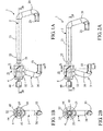
- the antitheft device 1 comprises two distinct parts 2, 3 forming jaws arranged to be assembled together and locked by a locking unit 4 through a wheel 11 of a vehicle 10 for block this wheel by being closer to it and prevent any movement of the vehicle.
- the two pieces 2 and 3 of the antitheft device 1 can be separated to store more easily in the vehicle 10, for example under the saddle, and in use, these two parts 2 and 3 can be assembled around and through one of the wheels 11 of the vehicle in an intimate manner to prevent any attempt of burglary.
- vehicle 10 is meant motorcycles but also all other similar vehicles with two, three or four wheels, motorized or not.
- the Figures 5, 6 , 8A and 8B schematically represent a motorcycle wheel by way of non-limiting example to illustrate the various mounting modes of the antitheft device 1, 1 '.
- One of the pieces of the antitheft device 1 forms a locking jaw 2 constituted by a J-shaped metal bar provided with a free end in the form of a hook 20 at a closed angle connected by a bend to a straight and elongate rod 21 intended to cross the rim 12 of a wheel 11, and terminated by a first assembly nozzle 22.
- the other piece of the antitheft device 1 forms a locking jaw 3 consisting of a C-shaped metal bar with one end free form hook 30 at a closed angle connected by a bend to a second connecting piece 32 located in the axis of the rod 21 to be coupled to the first connecting piece 22.
- These parts are generally made of a hardened steel for example cemented meets the standards in force concerning in particular the resistance to sawing, shearing, corrosion resistance, tensile strength.
- the locking block 4 is integrated with the assembly end 31 of the locking jaw 3 which is intended to be disposed against the rim 12 outside the wheel 11 as explained below.
- this locking block 4 could consist of a separate piece and attached to the assembled ends of said jaws or consists of two complementary parts respectively integrated to the assembly ends 22, 32 of the jaws 2, 3.
- the locking jaws 2 and locking jaws 3 each comprise at their hook-shaped free ends 20, 30 an interlocking zone 23, 33 specially profiled to be complementary to an existing fixed reception zone 13, 14 on the vehicle 10 and in which they are hooked.
- the receiving zone corresponds to a recess 13 existing in the brake caliper supports 15 fixed on the legs 16 of the fork 17 carrying the wheel 11.
- the receiving zone corresponds to a bore 14 existing at the base of the branches 16 of the fork 17 carrying the wheel 11 in the axis of said wheel.
- these receiving areas 13, 14 may be located in other places depending on the vehicle 10 considered.
- the shapes and dimensions of the interlocking zones 23, 33 provided at the hooked free end 20, 30 of the jaws 2, 3 are adapted to the shapes and dimensions of the receiving zones 13, 14 of said vehicle 10.
- FIGS 8A and 8B illustrate another example of mounting an antitheft device 1 'according to the invention which differs slightly from that described above.
- the parts identical to the previous example have the same reference numbers.
- the hook free ends 20 ', 30' of the locking jaws 2 'and locking jaws 3' are rounded to a radius of curvature substantially equal to that of the branches 16 of the fork 17 carrying a wheel 11d. a vehicle 10 so as to be able to hook around said branches 16.
- figure 8A schematically illustrates a first branch 16 of the fork 17 located on one side of the wheel 11 around which is hooked the hook free end 30 'of the locking jaw 3, while the Figure 8B illustrated schematically the second leg 16 of the same fork 17 located on the other side of the wheel 11 around which is hung the free hook end 20 'of the locking jaw 2'.
- the locking block 4 integrated in the assembly bit 32 of the locking jaw 3, 3 ' is shown in exploded view at the figure 7 and in axial section and transverse to FIGS. 3A, 3B and 4A, 4B respectively in its unlocked and locked positions.
- This blocking block 4 is housed in a central bore 35 formed in the assembly bit 32 and extended by a receiving orifice 36 intended to receive the assembly endpiece 22 of the locking jaw 2, 2 '.
- the assembly endpiece 22 is a male endpiece complementary to the assembly endpiece 32 which is a female endpiece.
- the locking block 4 comprises a removable key 40 for rotating a lock cylinder 41 guided in rotation and locked axially in a lock socket 42 by means of a first pin 46. lock 42 being in turn fixed in rotation in the connecting piece 32 by a second pin 47.
- the lock cylinder 41 controls by its flat central pin 43 the rotation of a ball cam 44 in said central bore 35.
- This central bore 35 comprises, in the example shown, three cam profiles 37 in equidistant recesses to cooperate with three balls 45 carried by the ball cam 44.
- the rotation of the ball cam 44 causes the displacement of the balls 45 between a retracted position ( Fig. 3A and 3B ) corresponding to the unlocked position of the antitheft device 1, 1 'and an output position ( Fig.
- the assembly end piece 22 of the locking jaw 2, 2 comprises at least one locking groove 25 disposed opposite the balls 45 when it is introduced into the assembly bit 32 to the inside of the receiving orifice 36 and inside a central recess 48 provided in the ball cam 44.
- the rotation of the ball cam 44 can be limited for example to 180 ° by a washer 49 travel limiter fitted on the flat central pin 43 and cooperating with radial stops provided on the lock sleeve 42.
- any other form of locking block 4 may be suitable, both mechanical with a key 40 than electronic using a magnetic card with or without contact.
- the assembly bit 22 comprises three successive locking grooves 25 separated by a regular pitch to determine three possible locking positions in order to adjust the wheelbase of the antitheft device 1 'to the wheel 11 of the vehicle 10 to be secured so as to have said antitheft device 1 'as close to the wheel 11 of said vehicle.
- the invention achieves the goals set, namely a very compact anti-theft device 1, 1 ', easy to store since the two jaws are detachable and quick to set up share and other of a wheel of a vehicle practically marrying said wheel, this preventing any attempted break-in. Tests have shown that an attempt to destroy this antitheft device would result in the damage or destruction of a part of the vehicle and not the antitheft device.
Landscapes
- Engineering & Computer Science (AREA)
- Mechanical Engineering (AREA)
- Lock And Its Accessories (AREA)
Description
- La présente invention concerne un dispositif antivol notamment pour motocyclette ou véhicule similaire selon la revendication 1. Ce dispositif antivol est amovible par rapport audit véhicule et est destiné à immobiliser au moins une roue dudit véhicule, ce dispositif comportant deux pièces distinctes agencées pour être respectivement couplées au véhicule de part et d'autre de ladite roue, pour être assemblées entre elles au travers de la jante de ladite roue et pour être verrouillées par un bloc de condamnation.
- L'utilisation de dispositifs antivol sur une motocyclette, un « trike » sorte de motocyclette à trois roues, un « quad » véhicule à trois ou quatre roues, ou tout autre véhicule similaire motorisé ou non, pose des problèmes récurrents qui résident dans l'encombrement de l'antivol lors de son transport et dans sa vulnérabilité aux actions de tiers lors de son utilisation.
- A ce jour, les seuls dispositifs antivol normalisés sont les antivols rigides en forme de U fermé par un barreau de verrouillage tels que ceux décrits dans les publications
US 3,805,564 etUS 5,921,115 , et les antivols à chaîne ou à câble tels que ceux décrits dans les publicationsUS 4,068,504 etDE 202004001273 . Néanmoins, tous les dispositifs antivol connus sont particulièrement encombrants et ne trouvent pas nécessairement une place de rangement optimisée dans le véhicule. Ces dispositifs antivol ont l'avantage de pouvoir se positionner à divers endroits du véhicule puisqu'ils sont suffisamment larges. Toutefois, ils ne permettent pas d'être positionnés au plus proche du cadre, d'une roue ou de toute autre partie du véhicule, en vue d'empêcher l'introduction d'une pince de cisaillement ou similaire visant à sectionner l'antivol. - Un exemple d'antivol en forme de U décrit dans la publication
FR-A-2 697 223 - Un autre type d'antivol décrit dans la publication
CN 2298994Y comporte deux brides, chacune fixée à demeure sur une des branches de la fourche avant du véhicule, et une tige de verrouillage agencée pour traverser les deux brides au travers de la jante de la roue du véhicule pour l'immobiliser. La tige de verrouillage peut être logée dans une position de rangement dans une des brides. Cette solution permet certes de faciliter le transport de l'antivol qui reste à demeure sur le véhicule, mais n'est pas optimale car elle alourdit la fourche, de manière non équilibrée, et peut être source d'accident. De plus, la tige de verrouillage positionnée latéralement sur une des branches de la fourche est dangereuse. L'antivol est par ailleurs soumis aux intempéries et aux projections de la route risquant d'endommager le bloc de condamnation. - Les publications
GB 2 303 598 US 6,434,980 décrivent des dispositifs antivol pourvus de deux pièces distinctes qui se montent à travers la jante d'une roue et se couplent au véhicule de part et d'autre de la roue. Toutefois, le verrouillage de ces dispositifs antivol nécessite un bloc de condamnation rapporté tel qu'un cadenas pouvant être facilement fractionné. De plus, ces dispositifs antivol sont encombrants donc compliqués à transporter, et leur ergonomie ne permet pas de les positionner au plus de la roue et/ou du cadre pour éviter les risques d'effraction. - La présente invention vise à pallier ces inconvénients en proposant un dispositif antivol qui répond aux normes en vigueur, dont l'encombrement en mode transport permet son rangement dans tout type de véhicule et dont la mise en oeuvre pour immobiliser un véhicule est simple, rapide, sécurisée, avec un risque d'effraction très limité voire supprimé.
- Dans ce but, l'invention concerne un dispositif antivol notamment pour motocyclette ou véhicule similaire, ce dispositif antivol étant amovible par rapport audit véhicule et étant agencé pour bloquer au moins une roue dudit véhicule, ce dispositif comportant deux pièces distinctes pouvant être séparées en mode de transport agencées pour être respectivement couplées au véhicule de part et d'autre de ladite roue, pour être assemblées entre elles au travers de la jante de ladite roue et pour être verrouillées par un bloc de condamnation, tel que lesdites pièces distinctes sont agencées pour s'assembler autour et au travers d'une des roues du véhicule de manière intime pour empêcher toute tentative d'effraction et en ce que l'une desdites pièces distinctes constitue une mâchoire de blocage en forme de J pourvue d'une extrémité libre en forme de crochet et d'une tige agencée pour traverser la jante de ladite roue en position d'utilisation et terminée par un premier embout d'assemblage, et l'autre desdites pièces distinctes constitue une mâchoire de verrouillage en forme de C pourvue d'une extrémité libre en forme de crochet et d'un second embout d'assemblage agencé pour se coupler audit premier embout d'assemblage et en ce que ledit bloc de condamnation est intégré à l'embout d'assemblage de ladite mâchoire de verrouillage qui est agencée pour être disposée contre la jante à l'extérieur de la roue, et en ce que lesdites mâchoires de blocage et de verrouillage comportent à leur extrémité libre en forme de crochet une zone d'emboîtement profilée agencée pour être complémentaire à une zone de réception dudit véhicule dans laquelle elles sont crochetées ou en ce que les extrémités libres en forme de crochet desdites mâchoires de blocage et de verrouillage sont complémentaires à une zone de réception dudit véhicule autour de laquelle elles sont crochetées.
- Cette construction particulière permet d'une part de positionner le dispositif antivol au plus près de la roue pour empêcher toute effraction et d'autre part de le transporter dans un encombrement réduit du véhicule.
- Selon l'invention, le bloc de condamnation est intégré à l'embout d'assemblage de la mâchoire de verrouillage pour une meilleure compacité du dispositif et une optimisation du nombre de composants.
L'un quelconque dudit premier embout d'assemblage de la mâchoire de blocage ou dudit second embout d'assemblage de la mâchoire de verrouillage est un embout mâle tandis que l'autre quelconque dudit second embout d'assemblage de la mâchoire de verrouillage ou dudit premier embout d'assemblage de la mâchoire de blocage est un embout femelle complémentaire audit embout mâle. - L'embout femelle comporte avantageusement le bloc de condamnation pourvu au moins d'un organe de verrouillage mobile entre une position escamotée correspondant à une position déverrouillée et une position sortie correspondant à une position verrouillée, tandis que l'embout mâle comporte au moins un logement de verrouillage agencé pour recevoir ledit organe de verrouillage en position sortie dans ladite position verrouillée.
- L'embout mâle peut comporter au moins deux logements de verrouillage successifs agencés pour définir au moins deux positions de verrouillage, chaque position de verrouillage correspondant à un empattement déterminé entre lesdites mâchoires.
- Chaque logement de verrouillage peut être constitué d'une gorge s'étendant autour dudit embout mâle, tandis que chaque organe de verrouillage peut être constitué d'une bille coopérant avec un profil de came agencé pour déplacer ladite bille entre ses positions escamotée et sortie par rapport audit logement de verrouillage.
- Dans la forme préférée de l'invention, l'embout mâle fait partie de ladite mâchoire de blocage et l'embout femelle pourvu dudit bloc de condamnation fait partie de ladite mâchoire de verrouillage.
- Dans une des variantes de réalisation, les mâchoires de blocage et de verrouillage comportent à leur extrémité libre en forme de crochet une zone d'emboîtement profilée agencée pour être complémentaire à une zone de réception dudit véhicule dans laquelle elles sont crochetées.
- Dans une autre variante de réalisation, les extrémités libres en forme de crochet desdites mâchoires de blocage et de verrouillage sont complémentaires à une zone de réception dudit véhicule autour de laquelle elles sont crochetées.
- La présente invention et ses avantages apparaîtront mieux dans la description suivante d'un mode de réalisation donné à titre d'exemple non limitatif, en référence aux dessins annexés, dans lesquels :
- la
figure 1A est une vue en plan d'un dispositif antivol selon l'invention en position ouverte, et lafigure 1B est une vue en coupe selon le plan AA de lafigure 1A , - les
figures 2A et 2B sont des vues similaires auxfigures 1A et 1B du dispositif antivol en position fermée, - la
figure 3A est une vue en coupe selon le plan BB du détail D du dispositif antivol de lafigure 1A en position ouverte, et lafigure 3B est une vue en coupe selon le plan CC du dispositif de lafigure 3A , - les
figures 4A et 4B sont des vues similaires auxfigures 3A et 3B du dispositif antivol en position fermée, - les
figures 5 et 6 sont des vues schématiques en perspective montrant deux modes de montage différents du dispositif antivol des figures précédentes, - la
figure 7 est une vue éclatée d'une variante de réalisation d'un dispositif antivol selon l'invention, et - les
figures 8A et 8B sont des vues schématiques en perspective montrant le mode de montage du dispositif antivol de lafigure 7 . - En référence aux figures, le dispositif antivol 1 selon l'invention comporte deux pièces distinctes 2, 3 formant des mâchoires agencées pour être assemblées entre elles et verrouillées par un bloc de condamnation 4 au travers d'une roue 11 d'un véhicule 10 pour bloquer cette roue en étant au plus près d'elle et empêcher tout déplacement du véhicule. Ainsi, en mode transport, les deux pièces 2 et 3 du dispositif antivol 1 peuvent être séparées pour se ranger plus facilement dans le véhicule 10, par exemple sous la selle, et en utilisation, ces deux pièces 2 et 3 peuvent s'assembler autour et au travers d'une des roues 11 du véhicule de manière intime pour empêcher toute tentative d'effraction. On entend par véhicule 10 les motocyclettes mais aussi tous les autres véhicules similaires à deux, trois ou quatre roues, motorisés ou non. Les
figures 5, 6 ,8A et 8B représentent schématiquement une roue de moto à titre d'exemple non limitatif pour illustrer les différents modes de montage du dispositif antivol 1, 1'. - Une des pièces du dispositif antivol 1 forme une mâchoire de blocage 2 constituée d'une barre métallique en forme de J pourvue d'une extrémité libre en forme de crochet 20 à angle fermé reliée par un coude à une tige 21 droite et allongée destinée à traverser la jante 12 d'une roue 11, et terminée par un premier embout d'assemblage 22. L'autre pièce du dispositif antivol 1 forme une mâchoire de verrouillage 3 constituée d'une barre métallique en forme de C pourvue d'une extrémité libre en forme de crochet 30 à angle fermé reliée par un coude à un second embout d'assemblage 32 situé dans l'axe de la tige 21 pour se coupler au premier embout d'assemblage 22. Ces pièces sont généralement réalisées dans un acier durci par exemple cémenté répondant aux normes en vigueur concernant notamment la résistance au sciage, au cisaillement, la résistance à la corrosion, la résistance à la traction.
- Selon l'invention, le bloc de condamnation 4 est intégré à l'embout d'assemblage 31 de la mâchoire de verrouillage 3 qui est destinée à être disposée contre la jante 12 à l'extérieur de la roue 11 comme expliqué plus loin. Dans des variantes de réalisation non représentées, qui ne font pas partie de l'invention, ce bloc de condamnation 4 pourrait être constitué d'une pièce séparée et rapportée sur les embouts assemblés desdites mâchoires ou constitué de deux parties complémentaires respectivement intégrées aux embouts d'assemblage 22, 32 des mâchoires 2, 3.
- Dans l'exemple illustré aux
figures 1 à 6 , les mâchoires de blocage 2 et de verrouillage 3 comportent chacune à leur extrémité libre en forme de crochet 20, 30 une zone d'emboîtement 23, 33 spécialement profilée pour être complémentaire à une zone de réception 13, 14 fixe existante sur le véhicule 10 et dans laquelle elles se crochètent. En référence à lafigure 5 , la zone de réception correspond à un évidement 13 existant dans les supports d'étrier de frein 15 fixés sur les branches 16 de la fourche 17 portant la roue 11. En référence à lafigure 6 , la zone de réception correspond à un alésage 14 existant à la base des branches 16 de la fourche 17 portant la roue 11 dans l'axe de ladite roue. Bien entendu, ces zones de réception 13, 14 peuvent être situées à d'autres endroits selon le véhicule 10 considéré. Dans ce cas, les formes et dimensions des zones d'emboîtement 23, 33 prévues à l'extrémité libre en crochet 20, 30 des mâchoires 2, 3 sont adaptées aux formes et dimensions des zones de réception 13, 14 dudit véhicule 10. - A ce sujet, les
figures 8A et 8B illustrent un autre exemple de montage d'un dispositif antivol 1' selon l'invention qui diffère légèrement de celui décrit précédemment. Les parties identiques à l'exemple précédent portent les mêmes numéros de référence. Dans cette variante de réalisation, les extrémités libres en crochet 20', 30' des mâchoires de blocage 2' et de verrouillage 3' sont arrondies suivant un rayon de courbure sensiblement égal à celui des branches 16 de la fourche 17 portant une roue 11 d'un véhicule 10 de manière à pouvoir se crocheter autour desdites branches 16. Lafigure 8A illustre schématiquement une première branche 16 de la fourche 17 située d'un côté de la roue 11 autour de laquelle est accrochée l'extrémité libre en crochet 30' de la mâchoire de verrouillage 3, tandis que lafigure 8B illustre schématiquement la seconde branche 16 de la même fourche 17 située de l'autre côté de la roue 11 autour de laquelle est accrochée l'extrémité libre en crochet 20' de la mâchoire de blocage 2'. - Le bloc de condamnation 4 intégré dans l'embout d'assemblage 32 de la mâchoire de verrouillage 3, 3' est représenté en vue éclatée à la
figure 7 et en coupe axiale et transversale auxfigures 3A, 3B et 4A, 4B respectivement dans ses positions déverrouillée et verrouillée. Ce bloc de condamnation 4 est logé dans un alésage central 35 ménagé dans l'embout d'assemblage 32 et prolongé par un orifice de réception 36 destiné à recevoir l'embout d'assemblage 22 de la mâchoire de blocage 2, 2'. Ainsi l'embout d'assemblage 22 est un embout mâle complémentaire à l'embout d'assemblage 32 qui est un embout femelle. - Le bloc de condamnation 4 comporte dans l'exemple représenté une clé 40 amovible pour commander en rotation un barillet de serrure 41 guidé en rotation et bloqué axialement dans une douille de serrure 42 par l'intermédiaire d'une première goupille 46, la douille de serrure 42 étant quant à elle fixe en rotation dans l'embout d'assemblage 32 par une seconde goupille 47. Le barillet de serrure 41 commande par son tenon central plat 43 la rotation d'une came à billes 44 dans ledit alésage central 35. Cet alésage central 35 comporte, dans l'exemple représenté, trois profils de came 37 en creux équidistants pour coopérer avec trois billes 45 portées par la came à billes 44. La rotation de la came à billes 44 provoque le déplacement des billes 45 entre une position escamotée (
fig. 3A et 3B ) correspondant à la position déverrouillée du dispositif antivol 1, 1' et une position sortie (fig. 4A et 4B ) correspondant à sa position verrouillée. A cet effet, l'embout d'assemblage 22 de la mâchoire de blocage 2, 2' comporte au moins une gorge de verrouillage 25 disposée en regard des billes 45 lorsqu'il est introduit dans l'embout d'assemblage 32 à l'intérieur de l'orifice de réception 36 et à l'intérieur d'un évidement central 48 prévu dans la came à billes 44. La rotation de la came à billes 44 peut être limitée par exemple à 180° par une rondelle 49 limiteur de course emboîtée sur le tenon central plat 43 et coopérant avec des butées radiales prévues sur la douille de serrure 42. Bien entendu toute autre forme de bloc de condamnation 4 peut convenir, aussi bien mécanique à l'aide d'une clé 40 qu'électronique à l'aide d'une carte magnétique avec ou sans contact. - Dans la variante de réalisation illustrée à la
figure 7 , l'embout d'assemblage 22 comporte trois gorges de verrouillage 25 successives et séparées d'un pas régulier pour déterminer trois positions de verrouillage possibles afin d'ajuster l'empattement du dispositif antivol 1' à la roue 11 du véhicule 10 à sécuriser de manière à pouvoir disposer ledit dispositif antivol 1 ' au plus près de la roue 11 dudit véhicule. - Il ressort clairement de cette description que l'invention permet d'atteindre les buts fixés, à savoir un dispositif antivol 1, 1' très compact, facile à ranger puisque les deux mâchoires sont détachables et rapide à mettre en place de part et d'autre d'une roue d'un véhicule en épousant pratiquement ladite roue, ceci empêchant toute tentative d'effraction. Les essais ont démontré qu'une tentative de destruction de ce dispositif antivol aurait pour conséquence l'endommagement voire la destruction d'une partie du véhicule et non du dispositif antivol.
- La présente invention n'est bien entendu pas limitée aux exemples de réalisation décrits mais s'étend à toute modification et variante évidentes pour un homme du métier tout en restant dans l'étendue de la protection définie dans les revendications annexées.
Claims (7)
- Dispositif antivol (1, 1') notamment pour motocyclette ou véhicule (10) similaire, ce dispositif antivol étant amovible par rapport audit véhicule (10) et étant agencé pour bloquer au moins une roue (11) dudit véhicule, ce dispositif comportant deux pièces (2, 3 ; 2', 3') distinctes pouvant être séparées en mode de transport agencées pour être respectivement couplées au véhicule (10) de part et d'autre de ladite roue (11), pour être assemblées entre elles au travers de la jante (12) de ladite roue (11) et pour être verrouillées par un bloc de condamnation (4), tel que lesdites pièces distinctes (2, 3 ; 2', 3') sont agencées pour s'assembler autour et au travers d'une des roues (11) du véhicule de manière intime pour empêcher toute tentative d'effraction et en ce que l'une desdites pièces distinctes constitue une mâchoire de blocage (2, 2') en forme de J pourvue d'une extrémité libre en forme de crochet (20, 20') et d'une tige (21) agencée pour traverser la jante (12) de ladite roue (11) en position d'utilisation et terminée par un premier embout d'assemblage (22), et l'autre desdites pièces distinctes constitue une mâchoire de verrouillage (3, 3') en forme de C pourvue d'une extrémité libre en forme de crochet (30, 30') et d'un second embout d'assemblage (32) agencé pour se coupler audit premier embout d'assemblage (22) et en ce que ledit bloc de condamnation (4) est intégré à l'embout d'assemblage (32) de ladite mâchoire de verrouillage (3, 3') qui est agencée pour être disposée contre la jante (12) à l'extérieur de la roue (11), et en ce que lesdites mâchoires de blocage (2) et de verrouillage (3) comportent à leur extrémité libre en forme de crochet (20, 30) une zone d'emboîtement profilée (23, 33) agencée pour être complémentaire à une zone de réception (13, 14) dudit véhicule (10) dans laquelle elles sont crochetées ou en ce que les extrémités libres en forme de crochet (20', 30') desdites mâchoires de blocage (2') et de verrouillage (3') sont complémentaires à une zone de réception (16) dudit véhicule (10) autour de laquelle elles sont crochetées.
- Dispositif antivol selon la revendication 1, caractérisé en ce que l'un quelconque dudit premier embout d'assemblage (22) de la mâchoire de blocage (2, 2') ou dudit second embout d'assemblage (32) de la mâchoire de verrouillage (3, 3') est un embout mâle et l'autre quelconque dudit second embout d'assemblage (32) de la mâchoire de verrouillage (3, 3') ou dudit premier embout d'assemblage (22) de la mâchoire de blocage (2, 2') est un embout femelle complémentaire audit embout mâle.
- Dispositif antivol selon la revendication 2, caractérisé en ce que ledit embout femelle (32) comporte ledit bloc de condamnation (4) pourvu au moins d'un organe de verrouillage (45) mobile entre une position escamotée correspondant à une position déverrouillée et une position sortie correspondant à une position verrouillée, et en ce que ledit embout mâle (22) comporte au moins un logement de verrouillage (25) agencé pour recevoir ledit organe de verrouillage (45) en position sortie dans ladite position verrouillée.
- Dispositif antivol selon la revendication 3, caractérisé en ce que ledit embout mâle (22) comporte au moins deux logements de verrouillage (25) successifs agencés pour définir au moins deux positions de verrouillage, chaque position de verrouillage correspondant à un empattement déterminé entre lesdites mâchoires (2, 3 ; 2', 3').
- Dispositif antivol selon l'une quelconque des revendications 3 ou 4, caractérisé en ce que chaque logement de verrouillage est constitué d'une gorge (25) s'étendant autour dudit embout mâle (22).
- Dispositif antivol selon l'une quelconque des revendications 3 ou 4, caractérisé en ce que chaque organe de verrouillage est constitué d'une bille (45) coopérant avec un profil de came (37) agencé pour déplacer ladite bille entre ses positions escamotée et sortie par rapport audit logement de verrouillage (25).
- Dispositif antivol selon l'une quelconque des revendications 3 à 6 caractérisé en ce que l'embout mâle (22) fait partie de ladite mâchoire de blocage (2, 2') et l'embout femelle (32) pourvu dudit bloc de condamnation (4) fait partie de ladite mâchoire de verrouillage (3, 3').
Applications Claiming Priority (1)
| Application Number | Priority Date | Filing Date | Title |
|---|---|---|---|
| FR1355032A FR3006289B1 (fr) | 2013-06-03 | 2013-06-03 | Dispositif antivol notamment pour motocyclette ou vehicule similaire |
Publications (2)
| Publication Number | Publication Date |
|---|---|
| EP2810858A1 EP2810858A1 (fr) | 2014-12-10 |
| EP2810858B1 true EP2810858B1 (fr) | 2018-11-28 |
Family
ID=49237298
Family Applications (1)
| Application Number | Title | Priority Date | Filing Date |
|---|---|---|---|
| EP14305839.4A Not-in-force EP2810858B1 (fr) | 2013-06-03 | 2014-06-03 | Dispositif antivol notamment pour motocyclette ou véhicule similaire |
Country Status (2)
| Country | Link |
|---|---|
| EP (1) | EP2810858B1 (fr) |
| FR (1) | FR3006289B1 (fr) |
Family Cites Families (10)
| Publication number | Priority date | Publication date | Assignee | Title |
|---|---|---|---|---|
| US3805564A (en) * | 1972-07-31 | 1974-04-23 | Raymond Lee Organization Inc | Lock unit for bicycle or motorcycle |
| US4068504A (en) * | 1976-07-26 | 1978-01-17 | Eleanor D. J. Stanford | Bicycle lock |
| GB8712621D0 (en) * | 1987-05-28 | 1987-07-01 | Bailey H | Ladder lock |
| IT1261318B (it) | 1992-10-28 | 1996-05-14 | Honda Giken Kogyo Kabuschiki K | Dispositivo antifurto per una motocicletta. |
| US5488844A (en) * | 1994-04-26 | 1996-02-06 | Winner International Royalty Corporation | Security device |
| GB2303598B (en) * | 1995-07-26 | 1998-12-16 | Mark Robert Suggitt | Bicycle lock |
| GB2314581A (en) * | 1996-06-26 | 1998-01-07 | Philip Simpson | Loop with lockable bracket for securing to a grate |
| CN2298994Y (zh) | 1997-04-11 | 1998-12-02 | 苏良进 | 机车锁 |
| US6434980B1 (en) * | 2001-08-20 | 2002-08-20 | Robert Foster | Tire clamp for immobilizing a vehicle |
| DE202004001273U1 (de) * | 2004-01-29 | 2004-04-01 | Welte, Rainer | Schloss für Zweiräder |
-
2013
- 2013-06-03 FR FR1355032A patent/FR3006289B1/fr not_active Expired - Fee Related
-
2014
- 2014-06-03 EP EP14305839.4A patent/EP2810858B1/fr not_active Not-in-force
Non-Patent Citations (1)
| Title |
|---|
| None * |
Also Published As
| Publication number | Publication date |
|---|---|
| FR3006289A1 (fr) | 2014-12-05 |
| FR3006289B1 (fr) | 2017-03-10 |
| EP2810858A1 (fr) | 2014-12-10 |
Similar Documents
| Publication | Publication Date | Title |
|---|---|---|
| EP2061692A1 (fr) | Dispositif antivol de pieces de velo | |
| EP2079631B1 (fr) | Dispositif antivol - blocage rapide de pieces de velo | |
| FR2639591A3 (fr) | Dispositif pour bloquer le volant de direction d'un vehicule afin d'empecher le vol de ce dernier | |
| EP2031289B1 (fr) | Dispositif de connexion pour circuit de climatisation ou de direction assistée de véhicule automobile, comprenant une bride et deux tubes la traversant | |
| EP2810858A1 (fr) | Dispositif antivol notamment pour motocyclette ou véhicule similaire | |
| EP4057972B1 (fr) | Systeme de liaison pour relier un fauteuil roulant a une trottinette dotee d'au moins une roue motorisee | |
| EP3243013B1 (fr) | Maillon démontable, adapté notamment à raccorder deux chaines pour l'ancrage au sol d'une installation flottante | |
| EP3530495B1 (fr) | Dispositif antivol amovible pour attelage | |
| EP1338474A1 (fr) | Dispositif de fixation d'un coffre de toit de véhicule sur un support | |
| EP2230411A1 (fr) | Système d'écrou de sécurité | |
| FR3009250A1 (fr) | Dispositif de fixation d'un objet embarque a l'arriere d'un vehicule automobile et procede de fixation associe | |
| FR2729364A1 (fr) | Dispositif antivol pour bicyclette | |
| FR2616182A1 (fr) | Raccord tubulaire entre arceaux de protection de vehicule | |
| EP1323881A2 (fr) | Poignée de véhicule automobile, en particulier pour une portière latérale | |
| EP0826582B1 (fr) | Dispositif de parcage de véhicules notamment de cycles | |
| EP0933289B1 (fr) | Cadenas | |
| EP1093430B1 (fr) | Dispositif d'immobilisation d'un vehicule notamment a deux roues | |
| FR2885344A1 (fr) | Dispositif antivol - blocage rapide de pieces de velo | |
| FR2893966A1 (fr) | Echelle de toit. | |
| FR2996872A1 (fr) | Dispositif de bridage d'un verrou pour une porte d'un vehicule automobile et vehicule automobile comprenant un tel dispositif de bridage | |
| EP3492362A1 (fr) | Attelage de remorque pour véhicule du type scooter | |
| EP1757821B1 (fr) | Dispositif d'ancrage à double mode de fixation | |
| FR2632924A1 (fr) | Dispositif antivol pour vehicule a au moins une roue | |
| FR2853616A1 (fr) | Antivol pour un cycle et sa selle | |
| EP1442938A1 (fr) | Article de bagagerie rigide et étanche destiné à être installé sur un toit de véhicule |
Legal Events
| Date | Code | Title | Description |
|---|---|---|---|
| PUAI | Public reference made under article 153(3) epc to a published international application that has entered the european phase |
Free format text: ORIGINAL CODE: 0009012 |
|
| 17P | Request for examination filed |
Effective date: 20140603 |
|
| AK | Designated contracting states |
Kind code of ref document: A1 Designated state(s): AL AT BE BG CH CY CZ DE DK EE ES FI FR GB GR HR HU IE IS IT LI LT LU LV MC MK MT NL NO PL PT RO RS SE SI SK SM TR |
|
| AX | Request for extension of the european patent |
Extension state: BA ME |
|
| R17P | Request for examination filed (corrected) |
Effective date: 20150609 |
|
| RBV | Designated contracting states (corrected) |
Designated state(s): AL AT BE BG CH CY CZ DE DK EE ES FI FR GB GR HR HU IE IS IT LI LT LU LV MC MK MT NL NO PL PT RO RS SE SI SK SM TR |
|
| GRAP | Despatch of communication of intention to grant a patent |
Free format text: ORIGINAL CODE: EPIDOSNIGR1 |
|
| STAA | Information on the status of an ep patent application or granted ep patent |
Free format text: STATUS: GRANT OF PATENT IS INTENDED |
|
| RIC1 | Information provided on ipc code assigned before grant |
Ipc: E05B 67/06 20060101ALN20180531BHEP Ipc: B62H 5/14 20060101AFI20180531BHEP Ipc: E05B 71/00 20060101ALI20180531BHEP |
|
| INTG | Intention to grant announced |
Effective date: 20180622 |
|
| GRAJ | Information related to disapproval of communication of intention to grant by the applicant or resumption of examination proceedings by the epo deleted |
Free format text: ORIGINAL CODE: EPIDOSDIGR1 |
|
| STAA | Information on the status of an ep patent application or granted ep patent |
Free format text: STATUS: REQUEST FOR EXAMINATION WAS MADE |
|
| GRAR | Information related to intention to grant a patent recorded |
Free format text: ORIGINAL CODE: EPIDOSNIGR71 |
|
| GRAS | Grant fee paid |
Free format text: ORIGINAL CODE: EPIDOSNIGR3 |
|
| STAA | Information on the status of an ep patent application or granted ep patent |
Free format text: STATUS: GRANT OF PATENT IS INTENDED |
|
| GRAA | (expected) grant |
Free format text: ORIGINAL CODE: 0009210 |
|
| STAA | Information on the status of an ep patent application or granted ep patent |
Free format text: STATUS: THE PATENT HAS BEEN GRANTED |
|
| INTC | Intention to grant announced (deleted) | ||
| AK | Designated contracting states |
Kind code of ref document: B1 Designated state(s): AL AT BE BG CH CY CZ DE DK EE ES FI FR GB GR HR HU IE IS IT LI LT LU LV MC MK MT NL NO PL PT RO RS SE SI SK SM TR |
|
| INTG | Intention to grant announced |
Effective date: 20181022 |
|
| RIC1 | Information provided on ipc code assigned before grant |
Ipc: B62H 5/14 20060101AFI20181019BHEP Ipc: E05B 67/06 20060101ALN20181019BHEP Ipc: E05B 71/00 20060101ALI20181019BHEP |
|
| REG | Reference to a national code |
Ref country code: CH Ref legal event code: EP |
|
| REG | Reference to a national code |
Ref country code: AT Ref legal event code: REF Ref document number: 1069900 Country of ref document: AT Kind code of ref document: T Effective date: 20181215 |
|
| REG | Reference to a national code |
Ref country code: IE Ref legal event code: FG4D Free format text: LANGUAGE OF EP DOCUMENT: FRENCH |
|
| REG | Reference to a national code |
Ref country code: DE Ref legal event code: R096 Ref document number: 602014036863 Country of ref document: DE |
|
| REG | Reference to a national code |
Ref country code: NL Ref legal event code: MP Effective date: 20181128 |
|
| REG | Reference to a national code |
Ref country code: LT Ref legal event code: MG4D |
|
| REG | Reference to a national code |
Ref country code: AT Ref legal event code: MK05 Ref document number: 1069900 Country of ref document: AT Kind code of ref document: T Effective date: 20181128 |
|
| PG25 | Lapsed in a contracting state [announced via postgrant information from national office to epo] |
Ref country code: HR Free format text: LAPSE BECAUSE OF FAILURE TO SUBMIT A TRANSLATION OF THE DESCRIPTION OR TO PAY THE FEE WITHIN THE PRESCRIBED TIME-LIMIT Effective date: 20181128 Ref country code: NO Free format text: LAPSE BECAUSE OF FAILURE TO SUBMIT A TRANSLATION OF THE DESCRIPTION OR TO PAY THE FEE WITHIN THE PRESCRIBED TIME-LIMIT Effective date: 20190228 Ref country code: LV Free format text: LAPSE BECAUSE OF FAILURE TO SUBMIT A TRANSLATION OF THE DESCRIPTION OR TO PAY THE FEE WITHIN THE PRESCRIBED TIME-LIMIT Effective date: 20181128 Ref country code: AT Free format text: LAPSE BECAUSE OF FAILURE TO SUBMIT A TRANSLATION OF THE DESCRIPTION OR TO PAY THE FEE WITHIN THE PRESCRIBED TIME-LIMIT Effective date: 20181128 Ref country code: BG Free format text: LAPSE BECAUSE OF FAILURE TO SUBMIT A TRANSLATION OF THE DESCRIPTION OR TO PAY THE FEE WITHIN THE PRESCRIBED TIME-LIMIT Effective date: 20190228 Ref country code: IS Free format text: LAPSE BECAUSE OF FAILURE TO SUBMIT A TRANSLATION OF THE DESCRIPTION OR TO PAY THE FEE WITHIN THE PRESCRIBED TIME-LIMIT Effective date: 20190328 Ref country code: LT Free format text: LAPSE BECAUSE OF FAILURE TO SUBMIT A TRANSLATION OF THE DESCRIPTION OR TO PAY THE FEE WITHIN THE PRESCRIBED TIME-LIMIT Effective date: 20181128 Ref country code: ES Free format text: LAPSE BECAUSE OF FAILURE TO SUBMIT A TRANSLATION OF THE DESCRIPTION OR TO PAY THE FEE WITHIN THE PRESCRIBED TIME-LIMIT Effective date: 20181128 Ref country code: FI Free format text: LAPSE BECAUSE OF FAILURE TO SUBMIT A TRANSLATION OF THE DESCRIPTION OR TO PAY THE FEE WITHIN THE PRESCRIBED TIME-LIMIT Effective date: 20181128 |
|
| PG25 | Lapsed in a contracting state [announced via postgrant information from national office to epo] |
Ref country code: RS Free format text: LAPSE BECAUSE OF FAILURE TO SUBMIT A TRANSLATION OF THE DESCRIPTION OR TO PAY THE FEE WITHIN THE PRESCRIBED TIME-LIMIT Effective date: 20181128 Ref country code: SE Free format text: LAPSE BECAUSE OF FAILURE TO SUBMIT A TRANSLATION OF THE DESCRIPTION OR TO PAY THE FEE WITHIN THE PRESCRIBED TIME-LIMIT Effective date: 20181128 Ref country code: GR Free format text: LAPSE BECAUSE OF FAILURE TO SUBMIT A TRANSLATION OF THE DESCRIPTION OR TO PAY THE FEE WITHIN THE PRESCRIBED TIME-LIMIT Effective date: 20190301 Ref country code: AL Free format text: LAPSE BECAUSE OF FAILURE TO SUBMIT A TRANSLATION OF THE DESCRIPTION OR TO PAY THE FEE WITHIN THE PRESCRIBED TIME-LIMIT Effective date: 20181128 Ref country code: PT Free format text: LAPSE BECAUSE OF FAILURE TO SUBMIT A TRANSLATION OF THE DESCRIPTION OR TO PAY THE FEE WITHIN THE PRESCRIBED TIME-LIMIT Effective date: 20190328 |
|
| PG25 | Lapsed in a contracting state [announced via postgrant information from national office to epo] |
Ref country code: NL Free format text: LAPSE BECAUSE OF FAILURE TO SUBMIT A TRANSLATION OF THE DESCRIPTION OR TO PAY THE FEE WITHIN THE PRESCRIBED TIME-LIMIT Effective date: 20181128 |
|
| PG25 | Lapsed in a contracting state [announced via postgrant information from national office to epo] |
Ref country code: PL Free format text: LAPSE BECAUSE OF FAILURE TO SUBMIT A TRANSLATION OF THE DESCRIPTION OR TO PAY THE FEE WITHIN THE PRESCRIBED TIME-LIMIT Effective date: 20181128 Ref country code: IT Free format text: LAPSE BECAUSE OF FAILURE TO SUBMIT A TRANSLATION OF THE DESCRIPTION OR TO PAY THE FEE WITHIN THE PRESCRIBED TIME-LIMIT Effective date: 20181128 Ref country code: DK Free format text: LAPSE BECAUSE OF FAILURE TO SUBMIT A TRANSLATION OF THE DESCRIPTION OR TO PAY THE FEE WITHIN THE PRESCRIBED TIME-LIMIT Effective date: 20181128 Ref country code: CZ Free format text: LAPSE BECAUSE OF FAILURE TO SUBMIT A TRANSLATION OF THE DESCRIPTION OR TO PAY THE FEE WITHIN THE PRESCRIBED TIME-LIMIT Effective date: 20181128 |
|
| REG | Reference to a national code |
Ref country code: DE Ref legal event code: R097 Ref document number: 602014036863 Country of ref document: DE |
|
| PG25 | Lapsed in a contracting state [announced via postgrant information from national office to epo] |
Ref country code: RO Free format text: LAPSE BECAUSE OF FAILURE TO SUBMIT A TRANSLATION OF THE DESCRIPTION OR TO PAY THE FEE WITHIN THE PRESCRIBED TIME-LIMIT Effective date: 20181128 Ref country code: SM Free format text: LAPSE BECAUSE OF FAILURE TO SUBMIT A TRANSLATION OF THE DESCRIPTION OR TO PAY THE FEE WITHIN THE PRESCRIBED TIME-LIMIT Effective date: 20181128 Ref country code: EE Free format text: LAPSE BECAUSE OF FAILURE TO SUBMIT A TRANSLATION OF THE DESCRIPTION OR TO PAY THE FEE WITHIN THE PRESCRIBED TIME-LIMIT Effective date: 20181128 Ref country code: SK Free format text: LAPSE BECAUSE OF FAILURE TO SUBMIT A TRANSLATION OF THE DESCRIPTION OR TO PAY THE FEE WITHIN THE PRESCRIBED TIME-LIMIT Effective date: 20181128 |
|
| PLBE | No opposition filed within time limit |
Free format text: ORIGINAL CODE: 0009261 |
|
| STAA | Information on the status of an ep patent application or granted ep patent |
Free format text: STATUS: NO OPPOSITION FILED WITHIN TIME LIMIT |
|
| PG25 | Lapsed in a contracting state [announced via postgrant information from national office to epo] |
Ref country code: SI Free format text: LAPSE BECAUSE OF FAILURE TO SUBMIT A TRANSLATION OF THE DESCRIPTION OR TO PAY THE FEE WITHIN THE PRESCRIBED TIME-LIMIT Effective date: 20181128 |
|
| 26N | No opposition filed |
Effective date: 20190829 |
|
| GBPC | Gb: european patent ceased through non-payment of renewal fee |
Effective date: 20190603 |
|
| PG25 | Lapsed in a contracting state [announced via postgrant information from national office to epo] |
Ref country code: TR Free format text: LAPSE BECAUSE OF FAILURE TO SUBMIT A TRANSLATION OF THE DESCRIPTION OR TO PAY THE FEE WITHIN THE PRESCRIBED TIME-LIMIT Effective date: 20181128 |
|
| PG25 | Lapsed in a contracting state [announced via postgrant information from national office to epo] |
Ref country code: GB Free format text: LAPSE BECAUSE OF NON-PAYMENT OF DUE FEES Effective date: 20190603 Ref country code: IE Free format text: LAPSE BECAUSE OF NON-PAYMENT OF DUE FEES Effective date: 20190603 |
|
| PGFP | Annual fee paid to national office [announced via postgrant information from national office to epo] |
Ref country code: MC Payment date: 20200519 Year of fee payment: 7 Ref country code: CH Payment date: 20200623 Year of fee payment: 7 Ref country code: DE Payment date: 20200612 Year of fee payment: 7 Ref country code: LU Payment date: 20200515 Year of fee payment: 7 |
|
| PGFP | Annual fee paid to national office [announced via postgrant information from national office to epo] |
Ref country code: BE Payment date: 20200616 Year of fee payment: 7 |
|
| PG25 | Lapsed in a contracting state [announced via postgrant information from national office to epo] |
Ref country code: CY Free format text: LAPSE BECAUSE OF FAILURE TO SUBMIT A TRANSLATION OF THE DESCRIPTION OR TO PAY THE FEE WITHIN THE PRESCRIBED TIME-LIMIT Effective date: 20181128 |
|
| PG25 | Lapsed in a contracting state [announced via postgrant information from national office to epo] |
Ref country code: MT Free format text: LAPSE BECAUSE OF FAILURE TO SUBMIT A TRANSLATION OF THE DESCRIPTION OR TO PAY THE FEE WITHIN THE PRESCRIBED TIME-LIMIT Effective date: 20181128 Ref country code: HU Free format text: LAPSE BECAUSE OF FAILURE TO SUBMIT A TRANSLATION OF THE DESCRIPTION OR TO PAY THE FEE WITHIN THE PRESCRIBED TIME-LIMIT; INVALID AB INITIO Effective date: 20140603 |
|
| REG | Reference to a national code |
Ref country code: DE Ref legal event code: R119 Ref document number: 602014036863 Country of ref document: DE |
|
| PG25 | Lapsed in a contracting state [announced via postgrant information from national office to epo] |
Ref country code: MC Free format text: LAPSE BECAUSE OF NON-PAYMENT OF DUE FEES Effective date: 20210630 |
|
| REG | Reference to a national code |
Ref country code: CH Ref legal event code: PL |
|
| REG | Reference to a national code |
Ref country code: BE Ref legal event code: MM Effective date: 20210630 |
|
| PG25 | Lapsed in a contracting state [announced via postgrant information from national office to epo] |
Ref country code: LU Free format text: LAPSE BECAUSE OF NON-PAYMENT OF DUE FEES Effective date: 20210603 |
|
| PG25 | Lapsed in a contracting state [announced via postgrant information from national office to epo] |
Ref country code: LI Free format text: LAPSE BECAUSE OF NON-PAYMENT OF DUE FEES Effective date: 20210630 Ref country code: DE Free format text: LAPSE BECAUSE OF NON-PAYMENT OF DUE FEES Effective date: 20220101 Ref country code: CH Free format text: LAPSE BECAUSE OF NON-PAYMENT OF DUE FEES Effective date: 20210630 |
|
| PG25 | Lapsed in a contracting state [announced via postgrant information from national office to epo] |
Ref country code: MK Free format text: LAPSE BECAUSE OF FAILURE TO SUBMIT A TRANSLATION OF THE DESCRIPTION OR TO PAY THE FEE WITHIN THE PRESCRIBED TIME-LIMIT Effective date: 20181128 |
|
| PG25 | Lapsed in a contracting state [announced via postgrant information from national office to epo] |
Ref country code: BE Free format text: LAPSE BECAUSE OF NON-PAYMENT OF DUE FEES Effective date: 20210630 |
|
| PGFP | Annual fee paid to national office [announced via postgrant information from national office to epo] |
Ref country code: FR Payment date: 20240626 Year of fee payment: 11 |
|
| PG25 | Lapsed in a contracting state [announced via postgrant information from national office to epo] |
Ref country code: FR Free format text: LAPSE BECAUSE OF NON-PAYMENT OF DUE FEES Effective date: 20250630 |