EP2810837B1 - Vehicle control device - Google Patents
Vehicle control device Download PDFInfo
- Publication number
- EP2810837B1 EP2810837B1 EP12867340.7A EP12867340A EP2810837B1 EP 2810837 B1 EP2810837 B1 EP 2810837B1 EP 12867340 A EP12867340 A EP 12867340A EP 2810837 B1 EP2810837 B1 EP 2810837B1
- Authority
- EP
- European Patent Office
- Prior art keywords
- engine
- torque
- generator
- command
- torque command
- Prior art date
- Legal status (The legal status is an assumption and is not a legal conclusion. Google has not performed a legal analysis and makes no representation as to the accuracy of the status listed.)
- Not-in-force
Links
Images


Classifications
-
- B—PERFORMING OPERATIONS; TRANSPORTING
- B60—VEHICLES IN GENERAL
- B60K—ARRANGEMENT OR MOUNTING OF PROPULSION UNITS OR OF TRANSMISSIONS IN VEHICLES; ARRANGEMENT OR MOUNTING OF PLURAL DIVERSE PRIME-MOVERS IN VEHICLES; AUXILIARY DRIVES FOR VEHICLES; INSTRUMENTATION OR DASHBOARDS FOR VEHICLES; ARRANGEMENTS IN CONNECTION WITH COOLING, AIR INTAKE, GAS EXHAUST OR FUEL SUPPLY OF PROPULSION UNITS IN VEHICLES
- B60K6/00—Arrangement or mounting of plural diverse prime-movers for mutual or common propulsion, e.g. hybrid propulsion systems comprising electric motors and internal combustion engines ; Control systems therefor, i.e. systems controlling two or more prime movers, or controlling one of these prime movers and any of the transmission, drive or drive units Informative references: mechanical gearings with secondary electric drive F16H3/72; arrangements for handling mechanical energy structurally associated with the dynamo-electric machine H02K7/00; machines comprising structurally interrelated motor and generator parts H02K51/00; dynamo-electric machines not otherwise provided for in H02K see H02K99/00
- B60K6/20—Arrangement or mounting of plural diverse prime-movers for mutual or common propulsion, e.g. hybrid propulsion systems comprising electric motors and internal combustion engines ; Control systems therefor, i.e. systems controlling two or more prime movers, or controlling one of these prime movers and any of the transmission, drive or drive units Informative references: mechanical gearings with secondary electric drive F16H3/72; arrangements for handling mechanical energy structurally associated with the dynamo-electric machine H02K7/00; machines comprising structurally interrelated motor and generator parts H02K51/00; dynamo-electric machines not otherwise provided for in H02K see H02K99/00 the prime-movers consisting of electric motors and internal combustion engines, e.g. HEVs
- B60K6/42—Arrangement or mounting of plural diverse prime-movers for mutual or common propulsion, e.g. hybrid propulsion systems comprising electric motors and internal combustion engines ; Control systems therefor, i.e. systems controlling two or more prime movers, or controlling one of these prime movers and any of the transmission, drive or drive units Informative references: mechanical gearings with secondary electric drive F16H3/72; arrangements for handling mechanical energy structurally associated with the dynamo-electric machine H02K7/00; machines comprising structurally interrelated motor and generator parts H02K51/00; dynamo-electric machines not otherwise provided for in H02K see H02K99/00 the prime-movers consisting of electric motors and internal combustion engines, e.g. HEVs characterised by the architecture of the hybrid electric vehicle
- B60K6/46—Series type
-
- B—PERFORMING OPERATIONS; TRANSPORTING
- B60—VEHICLES IN GENERAL
- B60W—CONJOINT CONTROL OF VEHICLE SUB-UNITS OF DIFFERENT TYPE OR DIFFERENT FUNCTION; CONTROL SYSTEMS SPECIALLY ADAPTED FOR HYBRID VEHICLES; ROAD VEHICLE DRIVE CONTROL SYSTEMS FOR PURPOSES NOT RELATED TO THE CONTROL OF A PARTICULAR SUB-UNIT
- B60W10/00—Conjoint control of vehicle sub-units of different type or different function
- B60W10/04—Conjoint control of vehicle sub-units of different type or different function including control of propulsion units
- B60W10/06—Conjoint control of vehicle sub-units of different type or different function including control of propulsion units including control of combustion engines
-
- B—PERFORMING OPERATIONS; TRANSPORTING
- B60—VEHICLES IN GENERAL
- B60W—CONJOINT CONTROL OF VEHICLE SUB-UNITS OF DIFFERENT TYPE OR DIFFERENT FUNCTION; CONTROL SYSTEMS SPECIALLY ADAPTED FOR HYBRID VEHICLES; ROAD VEHICLE DRIVE CONTROL SYSTEMS FOR PURPOSES NOT RELATED TO THE CONTROL OF A PARTICULAR SUB-UNIT
- B60W10/00—Conjoint control of vehicle sub-units of different type or different function
- B60W10/04—Conjoint control of vehicle sub-units of different type or different function including control of propulsion units
- B60W10/08—Conjoint control of vehicle sub-units of different type or different function including control of propulsion units including control of electric propulsion units, e.g. motors or generators
-
- B—PERFORMING OPERATIONS; TRANSPORTING
- B60—VEHICLES IN GENERAL
- B60W—CONJOINT CONTROL OF VEHICLE SUB-UNITS OF DIFFERENT TYPE OR DIFFERENT FUNCTION; CONTROL SYSTEMS SPECIALLY ADAPTED FOR HYBRID VEHICLES; ROAD VEHICLE DRIVE CONTROL SYSTEMS FOR PURPOSES NOT RELATED TO THE CONTROL OF A PARTICULAR SUB-UNIT
- B60W20/00—Control systems specially adapted for hybrid vehicles
- B60W20/50—Control strategies for responding to system failures, e.g. for fault diagnosis, failsafe operation or limp mode
-
- B—PERFORMING OPERATIONS; TRANSPORTING
- B60—VEHICLES IN GENERAL
- B60W—CONJOINT CONTROL OF VEHICLE SUB-UNITS OF DIFFERENT TYPE OR DIFFERENT FUNCTION; CONTROL SYSTEMS SPECIALLY ADAPTED FOR HYBRID VEHICLES; ROAD VEHICLE DRIVE CONTROL SYSTEMS FOR PURPOSES NOT RELATED TO THE CONTROL OF A PARTICULAR SUB-UNIT
- B60W50/00—Details of control systems for road vehicle drive control not related to the control of a particular sub-unit, e.g. process diagnostic or vehicle driver interfaces
- B60W50/02—Ensuring safety in case of control system failures, e.g. by diagnosing, circumventing or fixing failures
- B60W50/0205—Diagnosing or detecting failures; Failure detection models
-
- B—PERFORMING OPERATIONS; TRANSPORTING
- B60—VEHICLES IN GENERAL
- B60W—CONJOINT CONTROL OF VEHICLE SUB-UNITS OF DIFFERENT TYPE OR DIFFERENT FUNCTION; CONTROL SYSTEMS SPECIALLY ADAPTED FOR HYBRID VEHICLES; ROAD VEHICLE DRIVE CONTROL SYSTEMS FOR PURPOSES NOT RELATED TO THE CONTROL OF A PARTICULAR SUB-UNIT
- B60W50/00—Details of control systems for road vehicle drive control not related to the control of a particular sub-unit, e.g. process diagnostic or vehicle driver interfaces
- B60W50/02—Ensuring safety in case of control system failures, e.g. by diagnosing, circumventing or fixing failures
- B60W50/0225—Failure correction strategy
-
- B—PERFORMING OPERATIONS; TRANSPORTING
- B60—VEHICLES IN GENERAL
- B60W—CONJOINT CONTROL OF VEHICLE SUB-UNITS OF DIFFERENT TYPE OR DIFFERENT FUNCTION; CONTROL SYSTEMS SPECIALLY ADAPTED FOR HYBRID VEHICLES; ROAD VEHICLE DRIVE CONTROL SYSTEMS FOR PURPOSES NOT RELATED TO THE CONTROL OF A PARTICULAR SUB-UNIT
- B60W50/00—Details of control systems for road vehicle drive control not related to the control of a particular sub-unit, e.g. process diagnostic or vehicle driver interfaces
- B60W50/02—Ensuring safety in case of control system failures, e.g. by diagnosing, circumventing or fixing failures
- B60W50/038—Limiting the input power, torque or speed
-
- B—PERFORMING OPERATIONS; TRANSPORTING
- B60—VEHICLES IN GENERAL
- B60W—CONJOINT CONTROL OF VEHICLE SUB-UNITS OF DIFFERENT TYPE OR DIFFERENT FUNCTION; CONTROL SYSTEMS SPECIALLY ADAPTED FOR HYBRID VEHICLES; ROAD VEHICLE DRIVE CONTROL SYSTEMS FOR PURPOSES NOT RELATED TO THE CONTROL OF A PARTICULAR SUB-UNIT
- B60W2710/00—Output or target parameters relating to a particular sub-units
- B60W2710/08—Electric propulsion units
- B60W2710/083—Torque
-
- B—PERFORMING OPERATIONS; TRANSPORTING
- B60—VEHICLES IN GENERAL
- B60W—CONJOINT CONTROL OF VEHICLE SUB-UNITS OF DIFFERENT TYPE OR DIFFERENT FUNCTION; CONTROL SYSTEMS SPECIALLY ADAPTED FOR HYBRID VEHICLES; ROAD VEHICLE DRIVE CONTROL SYSTEMS FOR PURPOSES NOT RELATED TO THE CONTROL OF A PARTICULAR SUB-UNIT
- B60W2710/00—Output or target parameters relating to a particular sub-units
- B60W2710/08—Electric propulsion units
- B60W2710/086—Power
-
- Y—GENERAL TAGGING OF NEW TECHNOLOGICAL DEVELOPMENTS; GENERAL TAGGING OF CROSS-SECTIONAL TECHNOLOGIES SPANNING OVER SEVERAL SECTIONS OF THE IPC; TECHNICAL SUBJECTS COVERED BY FORMER USPC CROSS-REFERENCE ART COLLECTIONS [XRACs] AND DIGESTS
- Y02—TECHNOLOGIES OR APPLICATIONS FOR MITIGATION OR ADAPTATION AGAINST CLIMATE CHANGE
- Y02T—CLIMATE CHANGE MITIGATION TECHNOLOGIES RELATED TO TRANSPORTATION
- Y02T10/00—Road transport of goods or passengers
- Y02T10/60—Other road transportation technologies with climate change mitigation effect
- Y02T10/62—Hybrid vehicles
Definitions
- the present invention relates to a vehicle control apparatus that controls, for example, a hybrid vehicle.
- Patent Literature 1 Japanese Patent No. 3890459
- the document WO 2008/004418 A1 relates to a vehicle power output device which includes: a detection unit for detecting a failure of an electric connection path from a first connection terminal of a current control circuit via a battery to a second terminal of the current control circuit; and a control device for controlling the current control circuit and a motor generator.
- a detection unit for detecting a failure of an electric connection path from a first connection terminal of a current control circuit via a battery to a second terminal of the current control circuit
- a control device for controlling the current control circuit and a motor generator.
- the document EP 2 053 279 A2 discloses a method for reducing occurrence of clutch slip in electro-mechanical transmission adapted to selectively transmit mechanical power to an output member through selective application of a hydraulically actuated clutch includes monitoring operation of said clutch, identifying an indication of clutch wear based upon said monitoring said operation, and increasing a minimum clamping force applied to said clutch based upon said indication of clutch wear
- the conventional method is an idea to, if there is an abnormality in the air-fuel ratio sensor, change requested power at normal time to more limited single submerged-time limited power. Therefore, there is a problem in that fine power control and torque control for the engine cannot be performed.
- the power control and the torque control at normal time are complicated.
- the degree of an abnormality varies depending on various states of control. Therefore, it is desired to perform protective operation cooperation in which a plurality of protection levels are set rather than a single protection level.
- the present invention has been devised in view of the above and it is an object of the present invention to provide a vehicle control apparatus that can perform protective operation cooperation in which a plurality of protection levels are set.
- a vehicle control apparatus applied to a vehicle driving system that includes an engine, an engine controller that controls operation of the engine, a generator coupled to the engine, a converter that converts alternating-current power output by the generator into desired direct-current power, a load apparatus receives supply of the direct-current power from the converter and operate, and a rotating-speed detector that detects rotating speed of the generator, according to one aspect of the present invention is configured to be capable of controlling operations of the engine controller and the converter, wherein a host controller that collectively controls the engine controller and the converter is provided, the host controller includes: an engine-power-generation-command generating unit that generate an engine power generation command for causing the engine to operate and driving the generator, and outputs the engine power generation command to the engine controller; and a generator-torque-command generating unit that receives notch information in a plurality of stages included in the engine power generation command, select torque corresponding to magnitude of a notch, and output the selected torque to the converter as
- FIG. 1 is a diagram of a configuration example of a vehicle driving system including a vehicle control apparatus according to a first embodiment of the present invention.
- the configuration of the vehicle driving system applied to an engine system of a series hybrid system is shown.
- the vehicle driving system according to the first embodiment includes an engine 1, an engine controller 2, a generator 3, a converter 4, a speed sensor 5 functioning as a rotating speed detector, a host controller 6, and a load apparatus 7.
- the vehicle control apparatus according to the first embodiment includes, among these components, the generator 3, the converter 4, and the host controller 6.
- the vehicle control apparatus can include the engine 1, the engine controller 2, the speed sensor 5, and a part of the load apparatus 7.
- the engine 1 functions as an internal combustion engine, consumes fuel, and outputs a rotating force according to a fuel injection amount command 2a given by the engine controller 2.
- a rotating shaft of the engine 1 is directly connected to a rotating shaft of the generator 3.
- the rotating force of the engine 1 is directly transmitted to the generator 3.
- the generator 3 is generally a three-phase alternating-current generator.
- An output terminal of a stator three-phase winding wire is connected to the converter 4.
- the generator 3 converts the output of a mechanical rotating force from the engine 1 into three-phase alternating-current power and supplies the three-phase alternating-current power to the converter 4.
- the converter 4 converts the three-phase alternating-current power supplied from the generator 3 into direct-current power and supplies the direct-current power to the load apparatus 7.
- the load apparatus 7 includes, for example, an inverter device that converts the direct-current power into alternating-current power, a battery that stores the direct-current power, an electric motor that drives a vehicle, and a reduction gear that decelerates an output of the electric motor and transmits the output to an axle.
- an inverter device that converts the direct-current power into alternating-current power
- a battery that stores the direct-current power
- an electric motor that drives a vehicle
- a reduction gear that decelerates an output of the electric motor and transmits the output to an axle.
- the operation of the vehicle control apparatus including the function of the host controller 6 is explained.
- the host controller 6 includes, as shown in FIG. 1 , a generator-torque-command generating unit 10 and an engine-power-generation-command generating unit 11.
- the host controller 6 has a function of collectively performing cooperative control on the overall operation of the engine 1, the engine controller 2, the generator 3, and the converter 4.
- the engine-power-generation-command generating unit 11 outputs, to the engine controller 2, an engine power generation command 11a for causing the engine 1 to operate and driving the generator 3.
- the engine controller 2 adjusts the fuel injection amount command 2a according to the level of the engine power generation command 11a.
- the engine 1 is driven.
- An example of a driving control characteristic of the engine 1 of the engine controller 2 is shown in FIG. 3 .
- the abscissa represents rotating speed of an engine rotating shaft and the ordinate represents load torque that can be output.
- the engine power generation command is set to have a plurality of stages. When a larger engine power generation output is requested, the engine 1 is controlled to perform higher-speed rotation.
- the engine power generation command is set in three stages (three notches: 1N, 2N, and 3N).
- the engine-power-generation-command generating unit 11 when larger generated power is requested, the engine-power-generation-command generating unit 11 outputs engine power generation command 3N to the engine controller 2. When smaller generated power is requested, the engine-power-generation-command generating unit 11 outputs the engine power generation command 1N.
- the generator-torque-command generating unit 10 receives notch information 11b included in the engine power generation command 11a output to the engine controller 2 by the engine-power-generation-command generating unit 11.
- the generator-torque-command generating unit 10 selects a torque corresponding to the magnitude of the notch and outputs the selected torque to the converter 4 as a generator torque command 10a. Consequently, operating points of the speed and the torque in the engine 1 and the generator 3 are set according to levels of the engine power generation command, and the engine 1 and the generator 3 continue power generating operations at operating points indicated by circles in FIG. 3 . In this way, the host controller 6 controls the speed and the torque of the engine 1 and the generator 3 to thereby obtain desired generated power.
- the generator-torque-command generating unit 10 can be configured, for example, as shown in FIG. 2 . Note that the detailed configuration of the generator-torque-command generating unit 10 is explained below.
- FIGS. 1 , 4 , and 5 A protective cooperation operation between the engine 1 and the generator 3 forming the main part of the present invention is explained with reference to FIGS. 1 , 4 , and 5 .
- the generator-torque-command generating unit 10 always monitors a speed detection signal 5a of the speed sensor 5 that detects rotating shaft speed of the engine 1 and the generator 3.
- Abnormality determination speed K1 is set as a determination threshold for each of command levels, that is, for each of the notches of the engine-power-generation-command generating unit 11.
- the engine 1 sometimes cannot generate a mechanical output as commanded by the engine controller 2 because of a disorder or a failure of a part of components.
- the engine controller 2 detects the disorder or the failure according to information of sensors set in not-shown various components of the engine 1, reduces fuel injection amount, and shifts to a protection mode. Note that an example of an output torque characteristic obtained when such an output limitation is performed is shown in FIG. 4 .
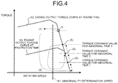
- FIG. 4 an operation state in the engine power generation command 2N shown in FIG. 3 is extracted and shown.
- the output torque of the engine 1 is reduced to decrease. Therefore, the output torque of the generator 3 becomes larger than the output torque of the engine 1.
- the output torque of the engine 1 and the output torque of the generator 3 are unbalanced and the difference between the output torque of the generator 3 and the output torque of the engine 1 acts as deceleration torque to the rotating shafts of the engine 1 and the generator 3 and the rotating speed decreases.
- This state is indicated by (1) in FIG. 4 .
- An operating point P present on an engine output torque curve K2 at the time of a sound operation i.e. an operation in good condition
- the generator-torque-command generating unit 10 recognizes an abnormality of the engine 1, provisionally selects a zero torque command value as a generator torque command, and reduces down to 0 [Nm]. This transition is indicated by (2) in FIG. 4 .
- the generator torque command becomes lower than an engine output torque curve K3 at protection time (a torque output curve for a protection mode of the engine 1), contrary to (1), the difference between the output torque of the generator 3 and the output torque of the engine 1 acts as acceleration torque to the rotating shafts of the engine 1 and the generator 3, and the rotating speed increases and returns to the original rotating speed.
- the generator-torque-command generating unit 10 outputs torque command values for abnormal time set in a plurality of stages in advance.
- the torque command values for abnormal time set in advance are applied in order from a torque command value for abnormal time 1 having the lowest value among the torque command values for abnormal time.
- the operating point P shifts to an operating point (3) in FIG. 4 .
- An application time T of the torque command value for abnormal time 1 in this transition period is set in advance. After the elapse of the time T, if the rotating speed is not lower than the abnormality determination speed, the generator-torque-command generating unit 10 increases the magnitude of the torque command for abnormal time to the next large level.
- the operating point P shifts to an operating point (4) in FIG. 4 .
- the generator-torque-command generating unit 10 increases the magnitude of the torque command value for abnormality detection to the next large level. In this way, unless the rotating speed falls below the abnormality determination speed, the torque command value for abnormal time is gradually increased.
- a generator torque command at the operating point (5) in this example is a torque command value for abnormal time in an Nth stage
- the generator-torque-command generating unit 10 selects and stores a torque command value for abnormal time in an (N-1)th stage as a limit value of generated generator torque applicable under an engine protection mode state.
- N 3.
- the generator-torque-command generating unit 10 recognizes an engine abnormality again and reduces the generator torque command to the lowest value of the torque command for abnormal time again to return the rotating speed to the original rotating speed. Thereafter, the generator-torque-command generating unit 10 outputs the torque command value for abnormal time in the (N-1)th stage as the limit value of the generator torque stored as explained above to continue operation. In the example shown in FIG. 4 , the operation is continued at the operating point (4).
- the generator-torque-command generating unit 10 includes, as shown in FIG. 2 , a sound-time-torque-command generating unit 100, a zero-torque-command generating unit 101, a torque-command-for-abnormal-time generating unit 102, a speed-abnormality detecting unit 103, a switching unit 104, and a change-ratio limiting unit 105.
- a torque command value at sound time output by the sound-time-torque-command generating unit 100 is selected and output by the switching unit 104.
- the speed-abnormality detecting unit 103 the before-mentioned abnormality determination speed K1 is set for each of engine notch conditions. While monitoring the notch information 11b of the engine and the speed detection signal 5a, when the speed-abnormality detecting unit 103 determines that the speed detection signal 5a falls below the abnormality determination speed K1 the speed-abnormality detecting unit 103 outputs a signal to the switching unit 104.
- the switching unit 104 selects, on the basis of the signal, a zero torque command value [0 [Nm]] output by the zero-torque-command generating unit 101 and outputs the zero torque command value. Thereafter, the switching unit 104 sequentially selects and outputs abnormal time torque command values 1 to M in a plurality of stages set in the torque-command-for-abnormal-time generating unit 102 in order from the lowest torque command value among the abnormal time torque command values.
- the speed-abnormality detecting unit 103 selects and stores the abnormal time torque command value in the (M-1)th stage as a limit value of generated generator torque in an engine protection mode, and also outputs a switching signal to the switching unit 104 to finally output the abnormal time torque command value in the (M-1)th stage as the generator torque command 10a.
- the change-ratio limiting unit 105 limits a change ratio with respect to a torque command increase or decrease.
- FIG. 5 is a diagram shown as a time chart of the operation transition explained above.
- the abscissa indicates time and the ordinate indicates engine speed (generator speed), abnormality determination speed, and generator torque.
- the time chart is explained below with reference to FIG. 1 , FIG. 4 , and FIG. 5 as appropriate.
- the generator-torque-command generating unit 10 searches for the magnitude of a torque command applicable in the generator 3.
- the generator-torque-command generating unit 10 selects and outputs torque equal to or lower than a limit value grasped as a result of the search to continue the operation. According to this control, even when an abnormality or a failure occurs in the engine 1 and an output is reduced, it is possible to search for applicable torque on the generator 3 side to continue the operation with the torque value, so that it is made possible to continue, although limitedly, power supply to an electric motor load for driving the vehicle and move the vehicle to a nearby garage or railway station where maintenance can be performed.
- Second Embodiment (which is not part of the invention).
- the search for a limit torque value applicable by the generator 3 when the output of the engine 1 is reduced because of an abnormality on the engine 1 side the method of increasing the torque command value for abnormal time stepwise from the smallest value is explained.
- the toque command value for abnormal time can be reduced stepwise from a largest value.
- this method is explained with reference to FIG. 1 , FIG. 6 , and FIG. 7 . Note that an operation until the engine 1 and the generator 3 shift to the protection mode because of a disorder or the like of a part of the components is the same as the operation in the first embodiment. Explanation of the operation is omitted.
- FIG. 6 an operation state in the engine power generation command 2N shown in FIG. 3 is extracted and shown.
- the output torque of the engine 1 is reduced to decrease. Therefore, a difference between the output torque of the generator 3 and the output torque of the engine 1 acts as deceleration torque to the rotating shafts of the engine 1 and the generator 3 and the rotating speed decreases.
- This state is indicated by (1) in FIG. 6 .
- the operating point P present on the engine output torque curve K2 at the time of a sound operation separates from K2 and shifts in the left direction.
- the generator-torque-command generating unit 10 recognizes an abnormality of the engine 1, provisionally reduces a generator torque command to a zero torque command value (0 [Nm]). This transition is indicated by (2) in FIG. 6 .
- the generator torque command becomes lower than the engine output torque curve K3 at protection time (a torque output curve for a protection mode of the engine 1), contrary to (1), the difference between the output torque of the generator 3 and the output torque of the engine 1 acts as acceleration torque to the rotating shafts of the engine 1 and the generator 3.
- the rotating speed increases and returns to the original rotating speed.
- the operation up to the rotating speed return operation is the same as the operation in the first embodiment.
- the generator-torque-command generating unit 10 outputs torque command values for abnormal time set in a plurality of stages in advance.
- torque command values for abnormal time in M stages set in advance are applied in order from a torque command value for abnormal time M having the highest value among the torque command values for abnormal time.
- the operating point P shifts to an operating point (A) in FIG. 6 .
- the selected torque output in the Mth stage of the torque command value for abnormal time is larger than the engine output torque at the protection mode time. Therefore, the difference between the output torque of the generator 3 and the output torque of the engine 1 acts as deceleration torque to the rotating shafts of the engine 1 and the generator 3 again and the rotating speed decreases. As a result, the rotating speed falls below the abnormality determination speed K1 again. Therefore, the generator-torque-command generating unit 10 recognizes an abnormality of the engine 1 again and reduces the generator torque command to the zero torque command value (0 [Nm]).
- the generator-torque-command generating unit 10 selects and outputs a torque command value for abnormal time (M-1) having the next highest torque value as the torque command value for abnormal time. As a result, the operating point P shifts to an operating point (B) in FIG. 6 .
- the generator-torque-command generating unit 10 recognizes an abnormality and reduces the generator torque command to the zero torque command value (0 [Nm]).
- the generator-torque-command generating unit 10 performs the control for selecting the torque command values for abnormal time for the generator 3 stepwise from the highest value until the speed of the generator 3 does not fall below the abnormality determination speed K1.
- FIG. 7 is a diagram shown as a time chart of the operation transition explained above.
- the abscissa indicates time and the ordinate indicates engine speed (generator speed), abnormality determination speed, and generator torque.
- the time chart is explained below with reference to FIG. 1 , FIG. 6 , and FIG. 7 as appropriate.
- the generator-torque-command generating unit 10 performs the control for selecting the torque command values for abnormal time for the generator 3 stepwise from the highest value until the speed of the generator 3 does not fall below the abnormality determination speed K1 therefore, even when an abnormality or a failure has occurred in the engine 1, it is possible to search for applicable torque on the generator 3 side to continue operation with the torque value. It is possible to continue, although limitedly, power supply to an electric motor load for driving the vehicle and move the vehicle to a nearby garage or railway station where maintenance can be performed.
- the present invention is useful as a vehicle control apparatus that can perform protective operation cooperation in which a plurality of protection levels are set.
Description
- The present invention relates to a vehicle control apparatus that controls, for example, a hybrid vehicle.
- There has been disclosed a technology for, in a hybrid vehicle capable of traveling by the power output from an electric motor, for the purpose of more properly determining whether or not a detection element used for detection of an air-fuel ratio of an internal combustion engine is submerged and securing traveling while protecting the detection element even when the detection element is submerged, determining an abnormality due to submerging of an air-fuel ratio sensor on the basis of element impedance of the air-fuel ratio sensor, controlling an engine and a motor such that requested power Pe* is output from the engine and requested torque Tr* is output to a driving shaft when there is no abnormality, and controlling the engine and the motor such that submerged-time limited power Pew obtained by limiting the requested power is output from the engine and the requested torque Tr* is output to the driving shaft when an abnormality is detected (e.g., Patent Literature 1).
- Patent Literature 1: Japanese Patent No.
3890459 - The document
WO 2008/004418 A1 relates to a vehicle power output device which includes: a detection unit for detecting a failure of an electric connection path from a first connection terminal of a current control circuit via a battery to a second terminal of the current control circuit; and a control device for controlling the current control circuit and a motor generator. When an engine is shifted from an operation state to a stop state and if the detection unit does not detect a failure, the control device causes the motor generator to perform generation operation to generate a negative torque to promote stop of the engine and causes the battery to collect the generated power. If the detection units detects a failure, the control device inhibits the generation operation of the motor generator. - The
document EP 2 053 279 A2 discloses a method for reducing occurrence of clutch slip in electro-mechanical transmission adapted to selectively transmit mechanical power to an output member through selective application of a hydraulically actuated clutch includes monitoring operation of said clutch, identifying an indication of clutch wear based upon said monitoring said operation, and increasing a minimum clamping force applied to said clutch based upon said indication of clutch wear - However, the conventional method is an idea to, if there is an abnormality in the air-fuel ratio sensor, change requested power at normal time to more limited single submerged-time limited power. Therefore, there is a problem in that fine power control and torque control for the engine cannot be performed. The power control and the torque control at normal time are complicated. The degree of an abnormality varies depending on various states of control. Therefore, it is desired to perform protective operation cooperation in which a plurality of protection levels are set rather than a single protection level.
- The present invention has been devised in view of the above and it is an object of the present invention to provide a vehicle control apparatus that can perform protective operation cooperation in which a plurality of protection levels are set.
- The invention is defined in
claim 1. In order to solve the aforementioned problems, a vehicle control apparatus applied to a vehicle driving system that includes an engine, an engine controller that controls operation of the engine, a generator coupled to the engine, a converter that converts alternating-current power output by the generator into desired direct-current power, a load apparatus receives supply of the direct-current power from the converter and operate, and a rotating-speed detector that detects rotating speed of the generator, according to one aspect of the present invention is configured to be capable of controlling operations of the engine controller and the converter, wherein a host controller that collectively controls the engine controller and the converter is provided, the host controller includes: an engine-power-generation-command generating unit that generate an engine power generation command for causing the engine to operate and driving the generator, and outputs the engine power generation command to the engine controller; and a generator-torque-command generating unit that receives notch information in a plurality of stages included in the engine power generation command, select torque corresponding to magnitude of a notch, and output the selected torque to the converter as a generator torque command, wherein the generator-torque-command generating unit monitors an abnormal operation of the engine on the basis of the engine power generation command and a detection signal of the rotating speed detector, switches, when the abnormal operation of the engine is detected, the generator torque command to the lowest value of a torque command value for abnormal time set in advance as the generator torque command, thereafter, gradually increases the generator torque command, and, after recording, as a torque limit value, magnitude of the generator torque command at the time when the abnormal operation of the engine is detected again, switches the generator torque command to a torque command value for abnormal time having a value smaller than the torque limit value. - According to the present invention, there is an effect that it is possible to perform protective operation cooperation in which a plurality of protection levels are set.
-
-
FIG. 1 is a diagram of a configuration example of a vehicle driving system including a vehicle control apparatus according to a first embodiment. -
FIG. 2 is a diagram of an example of an internal configuration for attaining the operation of a generator-torque-command generating unit shown inFIG. 1 . -
FIG. 3 is a diagram of an example of an engine driving control characteristic of an engine controller. -
FIG. 4 is a diagram of an example of an operation transition in the vehicle control apparatus according to the first embodiment. -
FIG. 5 is a diagram shown as a time chart of the example of the operation transition shown inFIG. 4 . -
FIG. 6 is a diagram of an example of an operation transition in a vehicle control apparatus according to a second embodiment. -
FIG. 7 is a diagram shown as a time chart of the example of the operation transition shown inFIG. 6 . - Vehicle control apparatuses according to embodiments of the present invention are explained below with reference to the accompanying drawings. Note that the present invention is not limited by the embodiments explained below.
-
FIG. 1 is a diagram of a configuration example of a vehicle driving system including a vehicle control apparatus according to a first embodiment of the present invention. The configuration of the vehicle driving system applied to an engine system of a series hybrid system is shown. As shown inFIG. 1 , the vehicle driving system according to the first embodiment includes anengine 1, anengine controller 2, agenerator 3, aconverter 4, aspeed sensor 5 functioning as a rotating speed detector, ahost controller 6, and a load apparatus 7. The vehicle control apparatus according to the first embodiment includes, among these components, thegenerator 3, theconverter 4, and thehost controller 6. Note that the vehicle control apparatus can include theengine 1, theengine controller 2, thespeed sensor 5, and a part of the load apparatus 7. - The
engine 1 functions as an internal combustion engine, consumes fuel, and outputs a rotating force according to a fuelinjection amount command 2a given by theengine controller 2. A rotating shaft of theengine 1 is directly connected to a rotating shaft of thegenerator 3. The rotating force of theengine 1 is directly transmitted to thegenerator 3. On the other hand, thegenerator 3 is generally a three-phase alternating-current generator. An output terminal of a stator three-phase winding wire is connected to theconverter 4. Thegenerator 3 converts the output of a mechanical rotating force from theengine 1 into three-phase alternating-current power and supplies the three-phase alternating-current power to theconverter 4. Theconverter 4 converts the three-phase alternating-current power supplied from thegenerator 3 into direct-current power and supplies the direct-current power to the load apparatus 7. Note that, although components of the load apparatus 7 are not shown in the figure, the load apparatus 7 includes, for example, an inverter device that converts the direct-current power into alternating-current power, a battery that stores the direct-current power, an electric motor that drives a vehicle, and a reduction gear that decelerates an output of the electric motor and transmits the output to an axle. - The operation of the vehicle control apparatus including the function of the
host controller 6 is explained. Thehost controller 6 includes, as shown inFIG. 1 , a generator-torque-command generatingunit 10 and an engine-power-generation-command generating unit 11. Thehost controller 6 has a function of collectively performing cooperative control on the overall operation of theengine 1, theengine controller 2, thegenerator 3, and theconverter 4. - The engine-power-generation-command generating
unit 11 outputs, to theengine controller 2, an enginepower generation command 11a for causing theengine 1 to operate and driving thegenerator 3. Theengine controller 2 adjusts the fuelinjection amount command 2a according to the level of the enginepower generation command 11a. Theengine 1 is driven. An example of a driving control characteristic of theengine 1 of theengine controller 2 is shown inFIG. 3 . InFIG. 3 , the abscissa represents rotating speed of an engine rotating shaft and the ordinate represents load torque that can be output. The engine power generation command is set to have a plurality of stages. When a larger engine power generation output is requested, theengine 1 is controlled to perform higher-speed rotation. In an example shown inFIG. 3 , the engine power generation command is set in three stages (three notches: 1N, 2N, and 3N). - In all the notches (IN, 2N, and 3N), when load torque applied to the rotating shaft is 0, the
engine 1 is rotated at maximum speed set by the characteristic of each of the notches. When the load torque increases, fuel injection is increased and output torque is increased according to the speed-torque characteristic set for each of the notches. Theengine 1 is driven with output torque equal to the load torque. Mechanical output [W] is a product of the speed and the output torque. Therefore, as the speed is higher or the output torque is larger, a larger mechanical output [W] is obtained. As a result, large electric power is obtained via thegenerator 3 and theconverter 4. Therefore, when explained with reference to the example shown inFIG. 3 , when larger generated power is requested, the engine-power-generation-command generatingunit 11 outputs enginepower generation command 3N to theengine controller 2. When smaller generated power is requested, the engine-power-generation-command generating unit 11 outputs the enginepower generation command 1N. - On the other hand, the generator-torque-
command generating unit 10 receivesnotch information 11b included in the enginepower generation command 11a output to theengine controller 2 by the engine-power-generation-command generating unit 11. The generator-torque-command generating unit 10 selects a torque corresponding to the magnitude of the notch and outputs the selected torque to theconverter 4 as agenerator torque command 10a. Consequently, operating points of the speed and the torque in theengine 1 and thegenerator 3 are set according to levels of the engine power generation command, and theengine 1 and thegenerator 3 continue power generating operations at operating points indicated by circles inFIG. 3 . In this way, thehost controller 6 controls the speed and the torque of theengine 1 and thegenerator 3 to thereby obtain desired generated power. The generator-torque-command generating unit 10 can be configured, for example, as shown inFIG. 2 . Note that the detailed configuration of the generator-torque-command generating unit 10 is explained below. - A protective cooperation operation between the
engine 1 and thegenerator 3 forming the main part of the present invention is explained with reference toFIGS. 1 ,4 , and5 . - The generator-torque-
command generating unit 10 always monitors aspeed detection signal 5a of thespeed sensor 5 that detects rotating shaft speed of theengine 1 and thegenerator 3. Abnormality determination speed K1 is set as a determination threshold for each of command levels, that is, for each of the notches of the engine-power-generation-command generating unit 11. - The
engine 1 sometimes cannot generate a mechanical output as commanded by theengine controller 2 because of a disorder or a failure of a part of components. In that case, theengine controller 2 detects the disorder or the failure according to information of sensors set in not-shown various components of theengine 1, reduces fuel injection amount, and shifts to a protection mode. Note that an example of an output torque characteristic obtained when such an output limitation is performed is shown inFIG. 4 . - In
FIG. 4 , an operation state in the enginepower generation command 2N shown inFIG. 3 is extracted and shown. When theengine 1 shifts to the protection mode, the output torque of theengine 1 is reduced to decrease. Therefore, the output torque of thegenerator 3 becomes larger than the output torque of theengine 1. As a result, the output torque of theengine 1 and the output torque of thegenerator 3 are unbalanced and the difference between the output torque of thegenerator 3 and the output torque of theengine 1 acts as deceleration torque to the rotating shafts of theengine 1 and thegenerator 3 and the rotating speed decreases. This state is indicated by (1) inFIG. 4 . An operating point P present on an engine output torque curve K2 at the time of a sound operation (i.e. an operation in good condition) separates from K2 and shifts in the left direction. - When the rotating speed decreases and falls below the abnormality determination speed K1 the generator-torque-
command generating unit 10 recognizes an abnormality of theengine 1, provisionally selects a zero torque command value as a generator torque command, and reduces down to 0 [Nm]. This transition is indicated by (2) inFIG. 4 . When the generator torque command becomes lower than an engine output torque curve K3 at protection time (a torque output curve for a protection mode of the engine 1), contrary to (1), the difference between the output torque of thegenerator 3 and the output torque of theengine 1 acts as acceleration torque to the rotating shafts of theengine 1 and thegenerator 3, and the rotating speed increases and returns to the original rotating speed. - Thereafter, the generator-torque-
command generating unit 10 outputs torque command values for abnormal time set in a plurality of stages in advance. In the first embodiment, as shown inFIG. 4 , the torque command values for abnormal time set in advance are applied in order from a torque command value forabnormal time 1 having the lowest value among the torque command values for abnormal time. As a result, the operating point P shifts to an operating point (3) inFIG. 4 . An application time T of the torque command value forabnormal time 1 in this transition period is set in advance. After the elapse of the time T, if the rotating speed is not lower than the abnormality determination speed, the generator-torque-command generating unit 10 increases the magnitude of the torque command for abnormal time to the next large level. The operating point P shifts to an operating point (4) inFIG. 4 . After the time T elapses again, if the rotating speed is not lower than the abnormality determination speed, the generator-torque-command generating unit 10 increases the magnitude of the torque command value for abnormality detection to the next large level. In this way, unless the rotating speed falls below the abnormality determination speed, the torque command value for abnormal time is gradually increased. - When the torque command value at abnormal time at a certain stage exceeds an output torque at the protection mode time on the
engine 1 side, the difference between the output torque of thegenerator 3 and the output torque of theengine 1 acts as the deceleration torque to the rotating shafts of the engine and the generator again and the rotating speed decreases. As a result, the rotating speed falls below the abnormality determination speed K1 again. Therefore, the generator-torque-command generating unit 10 recognizes an abnormality of theengine 1 again. This state is indicated by an operating point (5) inFIG. 4 . - When it is assumed that a generator torque command at the operating point (5) in this example is a torque command value for abnormal time in an Nth stage, the generator-torque-
command generating unit 10 selects and stores a torque command value for abnormal time in an (N-1)th stage as a limit value of generated generator torque applicable under an engine protection mode state. In an example shown inFIG. 4 , N=3. - Thereafter, the generator-torque-
command generating unit 10 recognizes an engine abnormality again and reduces the generator torque command to the lowest value of the torque command for abnormal time again to return the rotating speed to the original rotating speed. Thereafter, the generator-torque-command generating unit 10 outputs the torque command value for abnormal time in the (N-1)th stage as the limit value of the generator torque stored as explained above to continue operation. In the example shown inFIG. 4 , the operation is continued at the operating point (4). - Referring back to
FIG. 2 , the detailed configuration of the generator-torque-command generating unit 10 is explained. The generator-torque-command generating unit 10 includes, as shown inFIG. 2 , a sound-time-torque-command generating unit 100, a zero-torque-command generating unit 101, a torque-command-for-abnormal-time generating unit 102, a speed-abnormality detecting unit 103, aswitching unit 104, and a change-ratio limiting unit 105. - At normal time when the engine is soundly operating, i.e. operating in good condition, as the
generator torque command 10a, a torque command value at sound time output by the sound-time-torque-command generating unit 100 is selected and output by theswitching unit 104. On the other hand, in the speed-abnormality detecting unit 103, the before-mentioned abnormality determination speed K1 is set for each of engine notch conditions. While monitoring thenotch information 11b of the engine and thespeed detection signal 5a, when the speed-abnormality detecting unit 103 determines that thespeed detection signal 5a falls below the abnormality determination speed K1 the speed-abnormality detecting unit 103 outputs a signal to theswitching unit 104. Theswitching unit 104 selects, on the basis of the signal, a zero torque command value [0 [Nm]] output by the zero-torque-command generating unit 101 and outputs the zero torque command value. Thereafter, theswitching unit 104 sequentially selects and outputs abnormal timetorque command values 1 to M in a plurality of stages set in the torque-command-for-abnormal-time generating unit 102 in order from the lowest torque command value among the abnormal time torque command values. In a period in which the abnormal time torque command value M was output, when the speed-abnormality detecting unit 103 detects an abnormality again, the speed-abnormality detecting unit 103 selects and stores the abnormal time torque command value in the (M-1)th stage as a limit value of generated generator torque in an engine protection mode, and also outputs a switching signal to theswitching unit 104 to finally output the abnormal time torque command value in the (M-1)th stage as thegenerator torque command 10a. Note that, in the switching of a value of thegenerator torque command 10a, in order to avoid a stepwise torque change and smoothly apply torque to the generator, the change-ratio limiting unit 105 limits a change ratio with respect to a torque command increase or decrease. -
FIG. 5 is a diagram shown as a time chart of the operation transition explained above. The abscissa indicates time and the ordinate indicates engine speed (generator speed), abnormality determination speed, and generator torque. The time chart is explained below with reference toFIG. 1 ,FIG. 4 , andFIG. 5 as appropriate. - [1] First, when some abnormality occurs in the
engine 1, an abnormality of theengine 1 due to a rotating speed decrease of thegenerator 3 is detected. The generator torque command is reduced (step (a)). At this point, the operating point shifts from (1) to (2) (seeFIG. 4 ) . - [2] Subsequently, the generator torque command is sequentially increased. Torque limit values applicable to the
engine 1 are sequentially recorded (step (b)). At this point, the operating point shifts to (3), (4), and (5). - [3] When the operating point shifts to (5), the rotating speed of the
generator 3 decreases and an abnormality of theengine 1 is detected again. As a result, the generator torque command is reduced again. The operating point shifts to (2) (step (c)). - [4] Among generator torque commands serving as the torque limit values recorded in at step (b), a recorded value immediately before the generator torque command with which a decrease in the rotating speed of the
generator 3 was detected when the generator torque command is gradually increased is selected as a torque limit value. This torque limit value is applied as a generator torque command (step (d)). As a result, the operating point shifts to (4). - [5] Note that the generator torque command (in the example shown in
FIG. 4 , the torque command value for abnormal time 2) applied at step (d) is guaranteed that a decrease in the rotating seed is not detected in the processing at step (b). Therefore, at this operating point, it is possible to cause theengine 1 and thegenerator 3 to stably operate. - As explained above, with the vehicle control apparatus according to the first embodiment, when the
engine 1 and theengine controller 2 have shifted to the protection mode, the generator-torque-command generating unit 10 searches for the magnitude of a torque command applicable in thegenerator 3. The generator-torque-command generating unit 10 selects and outputs torque equal to or lower than a limit value grasped as a result of the search to continue the operation. According to this control, even when an abnormality or a failure occurs in theengine 1 and an output is reduced, it is possible to search for applicable torque on thegenerator 3 side to continue the operation with the torque value, so that it is made possible to continue, although limitedly, power supply to an electric motor load for driving the vehicle and move the vehicle to a nearby garage or railway station where maintenance can be performed. - Second Embodiment (which is not part of the invention). In the first embodiment, as the search for a limit torque value applicable by the
generator 3 when the output of theengine 1 is reduced because of an abnormality on theengine 1 side, the method of increasing the torque command value for abnormal time stepwise from the smallest value is explained. On the other hand, the toque command value for abnormal time can be reduced stepwise from a largest value. In a second embodiment, this method is explained with reference toFIG. 1 ,FIG. 6 , andFIG. 7 . Note that an operation until theengine 1 and thegenerator 3 shift to the protection mode because of a disorder or the like of a part of the components is the same as the operation in the first embodiment. Explanation of the operation is omitted. - In
FIG. 6 , an operation state in the enginepower generation command 2N shown inFIG. 3 is extracted and shown. When theengine 1 shifts to the protection mode, the output torque of theengine 1 is reduced to decrease. Therefore, a difference between the output torque of thegenerator 3 and the output torque of theengine 1 acts as deceleration torque to the rotating shafts of theengine 1 and thegenerator 3 and the rotating speed decreases. This state is indicated by (1) inFIG. 6 . As in the first embodiment, the operating point P present on the engine output torque curve K2 at the time of a sound operation separates from K2 and shifts in the left direction. - When the rotating speed decreases and falls below abnormality determination speed, the generator-torque-
command generating unit 10 recognizes an abnormality of theengine 1, provisionally reduces a generator torque command to a zero torque command value (0 [Nm]). This transition is indicated by (2) inFIG. 6 . When the generator torque command becomes lower than the engine output torque curve K3 at protection time (a torque output curve for a protection mode of the engine 1), contrary to (1), the difference between the output torque of thegenerator 3 and the output torque of theengine 1 acts as acceleration torque to the rotating shafts of theengine 1 and thegenerator 3. The rotating speed increases and returns to the original rotating speed. The operation up to the rotating speed return operation is the same as the operation in the first embodiment. - Thereafter, the generator-torque-
command generating unit 10 outputs torque command values for abnormal time set in a plurality of stages in advance. In the second embodiment, as shown inFIG. 6 , torque command values for abnormal time in M stages set in advance are applied in order from a torque command value for abnormal time M having the highest value among the torque command values for abnormal time. As a result, the operating point P shifts to an operating point (A) inFIG. 6 . - At the operating point (A) in this example, the selected torque output in the Mth stage of the torque command value for abnormal time is larger than the engine output torque at the protection mode time. Therefore, the difference between the output torque of the
generator 3 and the output torque of theengine 1 acts as deceleration torque to the rotating shafts of theengine 1 and thegenerator 3 again and the rotating speed decreases. As a result, the rotating speed falls below the abnormality determination speed K1 again. Therefore, the generator-torque-command generating unit 10 recognizes an abnormality of theengine 1 again and reduces the generator torque command to the zero torque command value (0 [Nm]). - Because the abnormality determination is performed again, the generator-torque-
command generating unit 10 selects and outputs a torque command value for abnormal time (M-1) having the next highest torque value as the torque command value for abnormal time. As a result, the operating point P shifts to an operating point (B) inFIG. 6 . - Thereafter, if the selected torque output in the (M-1)th stage is larger than the output torque of the
engine 1, the rotating speed further decreases again and falls below the abnormality determination speed. The generator-torque-command generating unit 10 recognizes an abnormality and reduces the generator torque command to the zero torque command value (0 [Nm]). - Further, thereafter, when a torque command for abnormal time (M-2) is selected and output, in
FIG. 6 , the operating point P shifts to an operating point (C). At the operating point (C), the selected torque output in the (M-1)th stage is smaller than the output torque of theengine 1. Therefore, the rotating speed stabilizes. If the next abnormality determination of the rotating speed does not occur even if time exceeds a time threshold T set in advance, the generator-torque-command generating unit 10 recognizes that a torque command level currently being output is a limit value of generator torque, continuously outputs the torque command value for abnormal time at the level, and causes theengine 1 and thegenerator 3 to continue a power generating operation. - In this way, the generator-torque-
command generating unit 10 performs the control for selecting the torque command values for abnormal time for thegenerator 3 stepwise from the highest value until the speed of thegenerator 3 does not fall below the abnormality determination speed K1. When an output decrease due to an output limitation in the protection mode of theengine 1 is low, there is an effect that it is possible to complete, earlier than in the first embodiment, the search for limit torque that can be output to thegenerator 3. -
FIG. 7 is a diagram shown as a time chart of the operation transition explained above. The abscissa indicates time and the ordinate indicates engine speed (generator speed), abnormality determination speed, and generator torque. The time chart is explained below with reference toFIG. 1 ,FIG. 6 , andFIG. 7 as appropriate. - [1] First, when some abnormality occurs in the
engine 1, an abnormality of theengine 1 due to a decrease in the rotating speed of thegenerator 3 is detected. The generator torque command is reduced (step (a)). At this point, the operating point shifts from (1) to (2) (seeFIG. 6 ) . - [2] Subsequently, the torque command value for abnormal time M is applied as the generator torque command. The operating point shifts to (A) (step (b)).
- [3] When the operating point shifts to (A), the rotating speed of the
generator 3 decreases and an abnormality of theengine 1 is detected again. As a result, the generator torque command is reduced again. The operating point shifts to (2) (step (c)). - [4] Subsequently, as the generator torque command, the torque command value for abnormal time (M-1) having a highest torque value next to the torque command value for abnormal time M selected at step (b) is applied. The operating point shifts to (B) (step (d)).
- [5] Like the operating point (A), the operating point (B) is an operating point where a decrease in the rotating speed of the
generator 3 is detected. Therefore, a reduction in the generator torque command is executed again. The operating point shifts to (2) (step (e)). - [6] Subsequently, as the generator torque command, the torque command value for abnormal time (M-2) having a highest torque value next to the torque command value for abnormal time (M-1) selected at step (d) is applied. The operating point shifts to (C) (step (f)).
- [7] Thereafter, as explained with reference to
FIG. 6 , the time when abnormality determination of the rotating speed does not occur is measured. If a measured value of the time exceeds the time threshold T set in advance, the torque command currently being output (the torque command value for abnormal time (M-2)) is continuously output. Theengine 1 and thegenerator 3 are caused to continue the power generating operation. - As explained above, with the vehicle control apparatus according to the second embodiment, when the
engine 1 and theengine controller 2 shift to the protection mode, the generator-torque-command generating unit 10 performs the control for selecting the torque command values for abnormal time for thegenerator 3 stepwise from the highest value until the speed of thegenerator 3 does not fall below the abnormality determination speed K1 therefore, even when an abnormality or a failure has occurred in theengine 1, it is possible to search for applicable torque on thegenerator 3 side to continue operation with the torque value. It is possible to continue, although limitedly, power supply to an electric motor load for driving the vehicle and move the vehicle to a nearby garage or railway station where maintenance can be performed. - As explained above, the present invention is useful as a vehicle control apparatus that can perform protective operation cooperation in which a plurality of protection levels are set.
-
- 1 Engine
- 2 Engine controller
- 2a Fuel injection amount command
- 3 Generator
- 4 Converter
- 5 Speed sensor
- 5a Detection signal
- 6 Host controller
- 7 Load apparatus
- 10 Generator-torque-command generating unit
- 10a Generator torque command
- 11 Engine-power-generation-command generating unit
- 11a Engine power generation command
- 11b Notch information
- 100 Sound-time-torque-command generating unit
- 101 Zero-torque-command generating unit
- 102 Torque-command-for-abnormal-time generating unit
- 103 Speed-abnormality detecting unit
- 104 Switching unit
- 105 Change-ratio limiting unit
Claims (2)
- A vehicle control apparatus applied to a vehicle driving system including: an engine (1); an engine controller (2) configured to control operation of the engine; a generator (3) coupled to the engine; a converter (4) configured to convert alternating-current power output by the generator (3) into desired direct-current power; a load apparatus (7) receiving supply of the direct-current power from the converter (4); and a rotating-speed detector (5) configured to detect rotating speed of the generator (3) ;
wherein the vehicle control apparatus is configured to be capable of controlling operations of the engine controller (2) and the converter (4), and
wherein a host controller (6), which is configured to collectively control the engine controller (2) and the converter (4), is provided;
the host controller includes:an engine-power-generation-command generating unit (11) configured to generate an engine power generation command (11a) for causing the engine (1) to operate and drive the generator (3), and to output the engine power generation command (11a) to the engine controller (2), wherein the engine power generation command (11a) is set to have a plurality of stages and wherein each stage corresponds to a notch; anda generator-torque-command generating unit (10) configured to:receive notch information in a plurality of stages included in the engine power generation command (11a),select torque corresponding to magnitude of one of the notches, wherein each of the notches has a set speed-torque characteristic, andoutput the selected torque to the converter (4) as a generator torque command (10a);wherein the generator-torque-command generating unit (10) is further configured to:monitor an abnormal operation of the engine (1) on the basis of the engine power generation command (11a) and a detection signal (5a) of the rotating speed detector (5),switche, when the abnormal operation of the engine (1) is detected, the generator torque command (10a) to the lowest value of a torque command value for an abnormal time set in advance as the generator torque command (10a),thereafter gradually increase the generator torque command (10a),recording, as a torque limit value, a magnitude of the generator torque command (10a) at the time when the abnormal operation of the engine (1) is detected again, andswitch the generator torque command (10a) to a torque command value for abnormal time having a value smaller than the recorded torque limit value. - The vehicle control apparatus according to claim 1, wherein
torque command values for abnormal time in M stages are set in advance in the host controller, wherein M is greater than 1, and
the generator-torque-command generating unit is configured to:select, when gradually increasing the generator torque command after detecting the abnormal operation of the engine, a torque command value for abnormal time in the smallest stage as the generator torque command,continue the monitoring of the abnormal operation of the engine while selecting a torque command value for abnormal time in the smallest stage next to the selected torque command value for abnormal time, andselect, when detecting the abnormal operation of the engine (1) when the torque command value for abnormal time in the Kth smallest stage is applied with K being a natural number smaller than M, a torque command value for abnormal time in the (K-1)th smallest stage as the generator torque command.
Applications Claiming Priority (1)
| Application Number | Priority Date | Filing Date | Title |
|---|---|---|---|
| PCT/JP2012/052162 WO2013114571A1 (en) | 2012-01-31 | 2012-01-31 | Vehicle control device |
Publications (3)
| Publication Number | Publication Date |
|---|---|
| EP2810837A1 EP2810837A1 (en) | 2014-12-10 |
| EP2810837A4 EP2810837A4 (en) | 2016-10-12 |
| EP2810837B1 true EP2810837B1 (en) | 2018-08-08 |
Family
ID=48904650
Family Applications (1)
| Application Number | Title | Priority Date | Filing Date |
|---|---|---|---|
| EP12867340.7A Not-in-force EP2810837B1 (en) | 2012-01-31 | 2012-01-31 | Vehicle control device |
Country Status (6)
| Country | Link |
|---|---|
| US (1) | US9738273B2 (en) |
| EP (1) | EP2810837B1 (en) |
| JP (1) | JP5602318B2 (en) |
| KR (1) | KR101542337B1 (en) |
| CN (1) | CN104080676B (en) |
| WO (1) | WO2013114571A1 (en) |
Families Citing this family (5)
| Publication number | Priority date | Publication date | Assignee | Title |
|---|---|---|---|---|
| CN104494416B (en) * | 2014-12-10 | 2017-06-13 | 北京航天发射技术研究所 | A kind of serial hybrid electric car EMS and method |
| JP6354769B2 (en) * | 2016-02-16 | 2018-07-11 | トヨタ自動車株式会社 | Hybrid vehicle |
| CN106428200B (en) * | 2016-12-05 | 2019-03-08 | 潍柴动力股份有限公司 | Multi-phase motor control method, controller and polyphase machine electric powered steering pumping system |
| FR3064235B1 (en) * | 2017-03-24 | 2019-03-22 | Continental Automotive France | METHOD FOR DETECTING COMBUSTION IRREGULARITIES OF AN INTERNAL COMBUSTION ENGINE TYPE UNIT COUPLED TO AN ELECTRIC PROPULSION UNIT OF A HYBRID MOTOR VEHICLE |
| DE102018208425A1 (en) * | 2018-05-28 | 2019-11-28 | Bayerische Motoren Werke Aktiengesellschaft | Drive train for a motor vehicle, in particular for a motor vehicle, and method for operating such a drive train |
Family Cites Families (18)
| Publication number | Priority date | Publication date | Assignee | Title |
|---|---|---|---|---|
| JPS58136719A (en) | 1982-02-05 | 1983-08-13 | Nippon Kokan Kk <Nkk> | Manufacture of high strength hot rolled steel plate |
| JP3890459B2 (en) | 1999-05-14 | 2007-03-07 | 日産自動車株式会社 | Engine automatic stop / restart vehicle |
| JP2003221648A (en) | 2001-11-20 | 2003-08-08 | Jfe Engineering Kk | High-strength hot-rolled steel sheet for picture tube frame, its manufacturing process and picture tube frame |
| JP4273768B2 (en) | 2001-12-28 | 2009-06-03 | Jfeスチール株式会社 | Hot-rolled steel sheet for iron core of rotating machine and manufacturing method thereof |
| JP4304421B2 (en) | 2002-10-23 | 2009-07-29 | 住友金属工業株式会社 | Hot rolled steel sheet |
| JP4152182B2 (en) * | 2002-12-24 | 2008-09-17 | ダイハツ工業株式会社 | Hybrid vehicle |
| JP4452191B2 (en) | 2005-02-02 | 2010-04-21 | 新日本製鐵株式会社 | Manufacturing method of high-stretch flange-formable hot-rolled steel sheet with excellent material uniformity |
| CN101900043B (en) * | 2005-10-28 | 2012-01-04 | 株式会社小松制作所 | Control device of engine, control device of engine and hydraulic pump, and control device of engine, hydraulic pump, and generator motor |
| JP2008014221A (en) | 2006-07-06 | 2008-01-24 | Denso Corp | Controller of engine with auxiliary machine |
| JP2008013119A (en) | 2006-07-07 | 2008-01-24 | Toyota Motor Corp | Power output device of vehicle and its control method |
| JP5197939B2 (en) | 2006-08-24 | 2013-05-15 | 株式会社日立製作所 | Railway vehicle drive system |
| JP5326403B2 (en) | 2007-07-31 | 2013-10-30 | Jfeスチール株式会社 | High strength steel plate |
| JP2009073410A (en) | 2007-09-21 | 2009-04-09 | Toyota Motor Corp | Hybrid vehicle and its control method |
| US8560191B2 (en) | 2007-10-26 | 2013-10-15 | GM Global Technology Operations LLC | Method and apparatus to control clutch pressures in an electro-mechanical transmission |
| US8428816B2 (en) * | 2007-10-27 | 2013-04-23 | GM Global Technology Operations LLC | Method and apparatus for monitoring software and signal integrity in a distributed control module system for a powertrain system |
| FR2927596A3 (en) * | 2008-02-18 | 2009-08-21 | Renault Sas | Power train controlling system controlling method for motor vehicle, involves deactivating degrade mode based on deactivation information representing intention of driver to obtain performance greater than reduced performance |
| JP5041084B2 (en) | 2010-03-31 | 2012-10-03 | Jfeスチール株式会社 | High-tensile hot-rolled steel sheet excellent in workability and manufacturing method thereof |
| JP5332051B2 (en) * | 2011-03-25 | 2013-11-06 | 株式会社小松製作所 | Engine, hydraulic pump and generator motor controller |
-
2012
- 2012-01-31 US US14/370,895 patent/US9738273B2/en active Active
- 2012-01-31 EP EP12867340.7A patent/EP2810837B1/en not_active Not-in-force
- 2012-01-31 CN CN201280068365.7A patent/CN104080676B/en not_active Expired - Fee Related
- 2012-01-31 WO PCT/JP2012/052162 patent/WO2013114571A1/en active Application Filing
- 2012-01-31 JP JP2013556126A patent/JP5602318B2/en not_active Expired - Fee Related
- 2012-01-31 KR KR1020147021046A patent/KR101542337B1/en active IP Right Grant
Non-Patent Citations (1)
| Title |
|---|
| None * |
Also Published As
| Publication number | Publication date |
|---|---|
| KR101542337B1 (en) | 2015-08-05 |
| EP2810837A1 (en) | 2014-12-10 |
| WO2013114571A1 (en) | 2013-08-08 |
| US20150006009A1 (en) | 2015-01-01 |
| US9738273B2 (en) | 2017-08-22 |
| CN104080676A (en) | 2014-10-01 |
| EP2810837A4 (en) | 2016-10-12 |
| KR20140107636A (en) | 2014-09-04 |
| CN104080676B (en) | 2016-10-19 |
| JP5602318B2 (en) | 2014-10-08 |
| JPWO2013114571A1 (en) | 2015-05-11 |
Similar Documents
| Publication | Publication Date | Title |
|---|---|---|
| CN101427456B (en) | Control system for an electric motor | |
| JP5886789B2 (en) | Apparatus and method for relay contact diagnosis of electric vehicle | |
| EP2810837B1 (en) | Vehicle control device | |
| EP2444293B1 (en) | Vehicle creep control device | |
| KR101484200B1 (en) | System for fail safe controlling of hybrid vehicle and method thereof | |
| US7573219B2 (en) | Drive belt slip detection | |
| US9186998B2 (en) | Method for operating an electrical system, and apparatus for controlling an electrical system | |
| US9333844B2 (en) | Method and device for operating a drive device of a vehicle | |
| US8198841B2 (en) | Method and circuit for processing a resolver fault | |
| US8810418B2 (en) | Vehicle fluid regulator valve diagnostic system | |
| EP2921337A2 (en) | Apparatus for controlling motor in electric vehicle and method for preventing overheating of traction motor | |
| KR100897097B1 (en) | Stuck perception method for engine clutch of hev | |
| KR20160055635A (en) | Driving control appratus for hybrid vehicle | |
| US9199651B2 (en) | Vehicle control apparatus and control method for hybrid vehicle for railroad | |
| KR102275282B1 (en) | Method for increasing the availability of a hybrid separating clutch in a hybrid drive train of a motor vehicle | |
| JP2013009487A (en) | Failure detection device for vehicle | |
| JP6381723B1 (en) | Control device and control method for rotating electrical machine | |
| EP2840704A1 (en) | Retarder | |
| KR102094989B1 (en) | BAS Self-Control Method Capable of Torque Assist and of Checking Engine Operating Conditions | |
| JP6004544B2 (en) | Drive control device, hybrid vehicle including the drive control device, and drive control method | |
| KR20170034134A (en) | Apparatus and method for control of engine clutch | |
| KR20120104672A (en) | Unit for driving oil pump for plug-in hybrid vehicle and method thereof |
Legal Events
| Date | Code | Title | Description |
|---|---|---|---|
| PUAI | Public reference made under article 153(3) epc to a published international application that has entered the european phase |
Free format text: ORIGINAL CODE: 0009012 |
|
| 17P | Request for examination filed |
Effective date: 20140724 |
|
| AK | Designated contracting states |
Kind code of ref document: A1 Designated state(s): AL AT BE BG CH CY CZ DE DK EE ES FI FR GB GR HR HU IE IS IT LI LT LU LV MC MK MT NL NO PL PT RO RS SE SI SK SM TR |
|
| AX | Request for extension of the european patent |
Extension state: BA ME |
|
| DAX | Request for extension of the european patent (deleted) | ||
| REG | Reference to a national code |
Ref country code: DE Ref legal event code: R079 Ref document number: 602012049663 Country of ref document: DE Free format text: PREVIOUS MAIN CLASS: B60W0010080000 Ipc: B60K0006460000 |
|
| RA4 | Supplementary search report drawn up and despatched (corrected) |
Effective date: 20160913 |
|
| RIC1 | Information provided on ipc code assigned before grant |
Ipc: B60W 20/50 20160101ALI20160907BHEP Ipc: B60W 50/038 20120101ALI20160907BHEP Ipc: B60W 50/02 20120101ALI20160907BHEP Ipc: B60K 6/46 20071001AFI20160907BHEP Ipc: B60W 10/08 20060101ALI20160907BHEP Ipc: B60W 10/06 20060101ALI20160907BHEP |
|
| STAA | Information on the status of an ep patent application or granted ep patent |
Free format text: STATUS: EXAMINATION IS IN PROGRESS |
|
| 17Q | First examination report despatched |
Effective date: 20170804 |
|
| GRAP | Despatch of communication of intention to grant a patent |
Free format text: ORIGINAL CODE: EPIDOSNIGR1 |
|
| STAA | Information on the status of an ep patent application or granted ep patent |
Free format text: STATUS: GRANT OF PATENT IS INTENDED |
|
| INTG | Intention to grant announced |
Effective date: 20180326 |
|
| GRAS | Grant fee paid |
Free format text: ORIGINAL CODE: EPIDOSNIGR3 |
|
| GRAA | (expected) grant |
Free format text: ORIGINAL CODE: 0009210 |
|
| STAA | Information on the status of an ep patent application or granted ep patent |
Free format text: STATUS: THE PATENT HAS BEEN GRANTED |
|
| AK | Designated contracting states |
Kind code of ref document: B1 Designated state(s): AL AT BE BG CH CY CZ DE DK EE ES FI FR GB GR HR HU IE IS IT LI LT LU LV MC MK MT NL NO PL PT RO RS SE SI SK SM TR |
|
| REG | Reference to a national code |
Ref country code: GB Ref legal event code: FG4D |
|
| REG | Reference to a national code |
Ref country code: CH Ref legal event code: EP Ref country code: AT Ref legal event code: REF Ref document number: 1026587 Country of ref document: AT Kind code of ref document: T Effective date: 20180815 |
|
| REG | Reference to a national code |
Ref country code: IE Ref legal event code: FG4D |
|
| REG | Reference to a national code |
Ref country code: DE Ref legal event code: R096 Ref document number: 602012049663 Country of ref document: DE |
|
| REG | Reference to a national code |
Ref country code: NL Ref legal event code: MP Effective date: 20180808 |
|
| REG | Reference to a national code |
Ref country code: LT Ref legal event code: MG4D |
|
| REG | Reference to a national code |
Ref country code: AT Ref legal event code: MK05 Ref document number: 1026587 Country of ref document: AT Kind code of ref document: T Effective date: 20180808 |
|
| PG25 | Lapsed in a contracting state [announced via postgrant information from national office to epo] |
Ref country code: FI Free format text: LAPSE BECAUSE OF FAILURE TO SUBMIT A TRANSLATION OF THE DESCRIPTION OR TO PAY THE FEE WITHIN THE PRESCRIBED TIME-LIMIT Effective date: 20180808 Ref country code: IS Free format text: LAPSE BECAUSE OF FAILURE TO SUBMIT A TRANSLATION OF THE DESCRIPTION OR TO PAY THE FEE WITHIN THE PRESCRIBED TIME-LIMIT Effective date: 20181208 Ref country code: RS Free format text: LAPSE BECAUSE OF FAILURE TO SUBMIT A TRANSLATION OF THE DESCRIPTION OR TO PAY THE FEE WITHIN THE PRESCRIBED TIME-LIMIT Effective date: 20180808 Ref country code: NO Free format text: LAPSE BECAUSE OF FAILURE TO SUBMIT A TRANSLATION OF THE DESCRIPTION OR TO PAY THE FEE WITHIN THE PRESCRIBED TIME-LIMIT Effective date: 20181108 Ref country code: SE Free format text: LAPSE BECAUSE OF FAILURE TO SUBMIT A TRANSLATION OF THE DESCRIPTION OR TO PAY THE FEE WITHIN THE PRESCRIBED TIME-LIMIT Effective date: 20180808 Ref country code: AT Free format text: LAPSE BECAUSE OF FAILURE TO SUBMIT A TRANSLATION OF THE DESCRIPTION OR TO PAY THE FEE WITHIN THE PRESCRIBED TIME-LIMIT Effective date: 20180808 Ref country code: GR Free format text: LAPSE BECAUSE OF FAILURE TO SUBMIT A TRANSLATION OF THE DESCRIPTION OR TO PAY THE FEE WITHIN THE PRESCRIBED TIME-LIMIT Effective date: 20181109 Ref country code: NL Free format text: LAPSE BECAUSE OF FAILURE TO SUBMIT A TRANSLATION OF THE DESCRIPTION OR TO PAY THE FEE WITHIN THE PRESCRIBED TIME-LIMIT Effective date: 20180808 Ref country code: BG Free format text: LAPSE BECAUSE OF FAILURE TO SUBMIT A TRANSLATION OF THE DESCRIPTION OR TO PAY THE FEE WITHIN THE PRESCRIBED TIME-LIMIT Effective date: 20181108 Ref country code: LT Free format text: LAPSE BECAUSE OF FAILURE TO SUBMIT A TRANSLATION OF THE DESCRIPTION OR TO PAY THE FEE WITHIN THE PRESCRIBED TIME-LIMIT Effective date: 20180808 Ref country code: PL Free format text: LAPSE BECAUSE OF FAILURE TO SUBMIT A TRANSLATION OF THE DESCRIPTION OR TO PAY THE FEE WITHIN THE PRESCRIBED TIME-LIMIT Effective date: 20180808 |
|
| REG | Reference to a national code |
Ref country code: CH Ref legal event code: PK Free format text: BERICHTIGUNGEN |
|
| RIC2 | Information provided on ipc code assigned after grant |
Ipc: B60W 20/50 20160101ALI20160907BHEP Ipc: B60W 50/038 20120101ALI20160907BHEP Ipc: B60W 10/06 20060101ALI20160907BHEP Ipc: B60W 10/08 20060101ALI20160907BHEP Ipc: B60W 50/02 20120101ALI20160907BHEP Ipc: B60K 6/46 20071001AFI20160907BHEP |
|
| PG25 | Lapsed in a contracting state [announced via postgrant information from national office to epo] |
Ref country code: AL Free format text: LAPSE BECAUSE OF FAILURE TO SUBMIT A TRANSLATION OF THE DESCRIPTION OR TO PAY THE FEE WITHIN THE PRESCRIBED TIME-LIMIT Effective date: 20180808 Ref country code: LV Free format text: LAPSE BECAUSE OF FAILURE TO SUBMIT A TRANSLATION OF THE DESCRIPTION OR TO PAY THE FEE WITHIN THE PRESCRIBED TIME-LIMIT Effective date: 20180808 Ref country code: HR Free format text: LAPSE BECAUSE OF FAILURE TO SUBMIT A TRANSLATION OF THE DESCRIPTION OR TO PAY THE FEE WITHIN THE PRESCRIBED TIME-LIMIT Effective date: 20180808 |
|
| PG25 | Lapsed in a contracting state [announced via postgrant information from national office to epo] |
Ref country code: ES Free format text: LAPSE BECAUSE OF FAILURE TO SUBMIT A TRANSLATION OF THE DESCRIPTION OR TO PAY THE FEE WITHIN THE PRESCRIBED TIME-LIMIT Effective date: 20180808 Ref country code: RO Free format text: LAPSE BECAUSE OF FAILURE TO SUBMIT A TRANSLATION OF THE DESCRIPTION OR TO PAY THE FEE WITHIN THE PRESCRIBED TIME-LIMIT Effective date: 20180808 Ref country code: CZ Free format text: LAPSE BECAUSE OF FAILURE TO SUBMIT A TRANSLATION OF THE DESCRIPTION OR TO PAY THE FEE WITHIN THE PRESCRIBED TIME-LIMIT Effective date: 20180808 Ref country code: IT Free format text: LAPSE BECAUSE OF FAILURE TO SUBMIT A TRANSLATION OF THE DESCRIPTION OR TO PAY THE FEE WITHIN THE PRESCRIBED TIME-LIMIT Effective date: 20180808 Ref country code: EE Free format text: LAPSE BECAUSE OF FAILURE TO SUBMIT A TRANSLATION OF THE DESCRIPTION OR TO PAY THE FEE WITHIN THE PRESCRIBED TIME-LIMIT Effective date: 20180808 |
|
| REG | Reference to a national code |
Ref country code: DE Ref legal event code: R097 Ref document number: 602012049663 Country of ref document: DE |
|
| PG25 | Lapsed in a contracting state [announced via postgrant information from national office to epo] |
Ref country code: DK Free format text: LAPSE BECAUSE OF FAILURE TO SUBMIT A TRANSLATION OF THE DESCRIPTION OR TO PAY THE FEE WITHIN THE PRESCRIBED TIME-LIMIT Effective date: 20180808 Ref country code: SM Free format text: LAPSE BECAUSE OF FAILURE TO SUBMIT A TRANSLATION OF THE DESCRIPTION OR TO PAY THE FEE WITHIN THE PRESCRIBED TIME-LIMIT Effective date: 20180808 Ref country code: SK Free format text: LAPSE BECAUSE OF FAILURE TO SUBMIT A TRANSLATION OF THE DESCRIPTION OR TO PAY THE FEE WITHIN THE PRESCRIBED TIME-LIMIT Effective date: 20180808 |
|
| PLBE | No opposition filed within time limit |
Free format text: ORIGINAL CODE: 0009261 |
|
| STAA | Information on the status of an ep patent application or granted ep patent |
Free format text: STATUS: NO OPPOSITION FILED WITHIN TIME LIMIT |
|
| 26N | No opposition filed |
Effective date: 20190509 |
|
| PG25 | Lapsed in a contracting state [announced via postgrant information from national office to epo] |
Ref country code: SI Free format text: LAPSE BECAUSE OF FAILURE TO SUBMIT A TRANSLATION OF THE DESCRIPTION OR TO PAY THE FEE WITHIN THE PRESCRIBED TIME-LIMIT Effective date: 20180808 Ref country code: MC Free format text: LAPSE BECAUSE OF FAILURE TO SUBMIT A TRANSLATION OF THE DESCRIPTION OR TO PAY THE FEE WITHIN THE PRESCRIBED TIME-LIMIT Effective date: 20180808 |
|
| REG | Reference to a national code |
Ref country code: CH Ref legal event code: PL |
|
| GBPC | Gb: european patent ceased through non-payment of renewal fee |
Effective date: 20190131 |
|
| PG25 | Lapsed in a contracting state [announced via postgrant information from national office to epo] |
Ref country code: LU Free format text: LAPSE BECAUSE OF NON-PAYMENT OF DUE FEES Effective date: 20190131 |
|
| REG | Reference to a national code |
Ref country code: BE Ref legal event code: MM Effective date: 20190131 |
|
| REG | Reference to a national code |
Ref country code: IE Ref legal event code: MM4A |
|
| PG25 | Lapsed in a contracting state [announced via postgrant information from national office to epo] |
Ref country code: FR Free format text: LAPSE BECAUSE OF NON-PAYMENT OF DUE FEES Effective date: 20190131 |
|
| PG25 | Lapsed in a contracting state [announced via postgrant information from national office to epo] |
Ref country code: BE Free format text: LAPSE BECAUSE OF NON-PAYMENT OF DUE FEES Effective date: 20190131 |
|
| PG25 | Lapsed in a contracting state [announced via postgrant information from national office to epo] |
Ref country code: CH Free format text: LAPSE BECAUSE OF NON-PAYMENT OF DUE FEES Effective date: 20190131 Ref country code: GB Free format text: LAPSE BECAUSE OF NON-PAYMENT OF DUE FEES Effective date: 20190131 Ref country code: LI Free format text: LAPSE BECAUSE OF NON-PAYMENT OF DUE FEES Effective date: 20190131 |
|
| PG25 | Lapsed in a contracting state [announced via postgrant information from national office to epo] |
Ref country code: IE Free format text: LAPSE BECAUSE OF NON-PAYMENT OF DUE FEES Effective date: 20190131 |
|
| PG25 | Lapsed in a contracting state [announced via postgrant information from national office to epo] |
Ref country code: TR Free format text: LAPSE BECAUSE OF FAILURE TO SUBMIT A TRANSLATION OF THE DESCRIPTION OR TO PAY THE FEE WITHIN THE PRESCRIBED TIME-LIMIT Effective date: 20180808 |
|
| PG25 | Lapsed in a contracting state [announced via postgrant information from national office to epo] |
Ref country code: MT Free format text: LAPSE BECAUSE OF NON-PAYMENT OF DUE FEES Effective date: 20190131 Ref country code: PT Free format text: LAPSE BECAUSE OF FAILURE TO SUBMIT A TRANSLATION OF THE DESCRIPTION OR TO PAY THE FEE WITHIN THE PRESCRIBED TIME-LIMIT Effective date: 20181208 |
|
| PG25 | Lapsed in a contracting state [announced via postgrant information from national office to epo] |
Ref country code: CY Free format text: LAPSE BECAUSE OF FAILURE TO SUBMIT A TRANSLATION OF THE DESCRIPTION OR TO PAY THE FEE WITHIN THE PRESCRIBED TIME-LIMIT Effective date: 20180808 |
|
| PG25 | Lapsed in a contracting state [announced via postgrant information from national office to epo] |
Ref country code: HU Free format text: LAPSE BECAUSE OF FAILURE TO SUBMIT A TRANSLATION OF THE DESCRIPTION OR TO PAY THE FEE WITHIN THE PRESCRIBED TIME-LIMIT; INVALID AB INITIO Effective date: 20120131 |
|
| REG | Reference to a national code |
Ref country code: DE Ref legal event code: R084 Ref document number: 602012049663 Country of ref document: DE |
|
| PGFP | Annual fee paid to national office [announced via postgrant information from national office to epo] |
Ref country code: DE Payment date: 20211207 Year of fee payment: 11 |
|
| PG25 | Lapsed in a contracting state [announced via postgrant information from national office to epo] |
Ref country code: MK Free format text: LAPSE BECAUSE OF FAILURE TO SUBMIT A TRANSLATION OF THE DESCRIPTION OR TO PAY THE FEE WITHIN THE PRESCRIBED TIME-LIMIT Effective date: 20180808 |
|
| REG | Reference to a national code |
Ref country code: DE Ref legal event code: R119 Ref document number: 602012049663 Country of ref document: DE |
|
| PG25 | Lapsed in a contracting state [announced via postgrant information from national office to epo] |
Ref country code: DE Free format text: LAPSE BECAUSE OF NON-PAYMENT OF DUE FEES Effective date: 20230801 |