EP2810546B1 - Device for dispensing individual seeds - Google Patents
Device for dispensing individual seeds Download PDFInfo
- Publication number
- EP2810546B1 EP2810546B1 EP14170080.7A EP14170080A EP2810546B1 EP 2810546 B1 EP2810546 B1 EP 2810546B1 EP 14170080 A EP14170080 A EP 14170080A EP 2810546 B1 EP2810546 B1 EP 2810546B1
- Authority
- EP
- European Patent Office
- Prior art keywords
- disc
- drum
- seal
- vacuum chamber
- insert
- Prior art date
- Legal status (The legal status is an assumption and is not a legal conclusion. Google has not performed a legal analysis and makes no representation as to the accuracy of the status listed.)
- Active
Links
- 238000007789 sealing Methods 0.000 claims description 24
- 230000002093 peripheral effect Effects 0.000 claims description 19
- 238000009826 distribution Methods 0.000 claims description 17
- 239000000463 material Substances 0.000 claims description 6
- 230000006835 compression Effects 0.000 claims description 3
- 238000007906 compression Methods 0.000 claims description 3
- 239000007787 solid Substances 0.000 claims description 3
- 230000000295 complement effect Effects 0.000 claims description 2
- 238000010899 nucleation Methods 0.000 claims 2
- 238000012423 maintenance Methods 0.000 description 11
- 238000009331 sowing Methods 0.000 description 11
- 238000000034 method Methods 0.000 description 5
- 230000000694 effects Effects 0.000 description 4
- 230000002028 premature Effects 0.000 description 4
- 230000000284 resting effect Effects 0.000 description 4
- 238000005265 energy consumption Methods 0.000 description 3
- 239000004033 plastic Substances 0.000 description 3
- 108010016634 Seed Storage Proteins Proteins 0.000 description 2
- 229920006362 Teflon® Polymers 0.000 description 2
- 238000004026 adhesive bonding Methods 0.000 description 2
- 238000013461 design Methods 0.000 description 2
- 238000004519 manufacturing process Methods 0.000 description 2
- 229910000906 Bronze Inorganic materials 0.000 description 1
- 241001417494 Sciaenidae Species 0.000 description 1
- 238000013459 approach Methods 0.000 description 1
- 230000000903 blocking effect Effects 0.000 description 1
- 239000010974 bronze Substances 0.000 description 1
- 239000011248 coating agent Substances 0.000 description 1
- 238000000576 coating method Methods 0.000 description 1
- KUNSUQLRTQLHQQ-UHFFFAOYSA-N copper tin Chemical compound [Cu].[Sn] KUNSUQLRTQLHQQ-UHFFFAOYSA-N 0.000 description 1
- 229920001971 elastomer Polymers 0.000 description 1
- 239000000806 elastomer Substances 0.000 description 1
- 230000001939 inductive effect Effects 0.000 description 1
- 230000014759 maintenance of location Effects 0.000 description 1
- 238000004513 sizing Methods 0.000 description 1
- 239000002689 soil Substances 0.000 description 1
- 238000003756 stirring Methods 0.000 description 1
- 238000013519 translation Methods 0.000 description 1
Images


Classifications
-
- A—HUMAN NECESSITIES
- A01—AGRICULTURE; FORESTRY; ANIMAL HUSBANDRY; HUNTING; TRAPPING; FISHING
- A01C—PLANTING; SOWING; FERTILISING
- A01C7/00—Sowing
- A01C7/04—Single-grain seeders with or without suction devices
- A01C7/042—Single-grain seeders with or without suction devices using pneumatic means
- A01C7/044—Pneumatic seed wheels
- A01C7/046—Pneumatic seed wheels with perforated seeding discs
Definitions
- the invention relates to a unit for dispensing seeds of the vacuum type.
- a device with the characteristics of the preamble of claim 1 is known from EP 0 141 638 A2 .
- the document WO 2012/121658 A1 describes another pneumatic overpressure device, with means for ensuring airtightness between the drum and the disc.
- a drive shaft is rotatably mounted through the drum.
- a first end of the drive shaft extends outside the drum while a second end of the drive shaft extends inside the cavity.
- the drive shaft is rotated via drive means provided for this purpose.
- the distributor disc is then driven in rotation.
- the turbine is used to generate a vacuum inside the vacuum chamber. Seeds are conveyed from seed storage means to the reservoir. Due to the vacuum prevailing inside the vacuum chamber, the seeds contained in the reservoir are sucked and come to be positioned one by one on the suction holes of the distributor disc located opposite the vacuum chamber.
- the disc is provided with a stirrer, consisting of a separate part on which the disc is fixed and which plays the role of stiffening the disc on the one hand, and on the other hand to agitate, to stir the seeds with its wings, which allows to better fix the seeds on the holes.
- This solution also makes it possible to ensure good sealing of the vacuum chamber. It also helps to obviate the problem linked to the premature wear of the drum and of the disc inherent in the first solution discussed above. However, due to the fact that the disc rubs against the seal, this seal is subject to wear which can be rapid, which requires the implementation of frequent and therefore costly maintenance campaigns.
- the invention discussed also relates to a seeder comprising at least one such sowing element.
- the blades can be welded or molded directly on the distributor disc 33, as long as the disc is sufficiently rigid.
- the cover 31 defines with the disc 33 a seed ejection zone 37.
- the elastic seal 38 preferably has a stiffness such that it exerts on the friction insert a force of between 10N and 100N per linear meter for a compression stroke of one millimeter.
- the elastic seal 38 keeps the friction insert resting against the distributor disc 33.
- the seeds are deposited individually in the furrow at regular intervals.
- the distributor disc 33 Due to its stiffness or its association with an agitator, the distributor disc 33 does not deform under the effect of the vacuum generated inside the vacuum chamber 34. It is therefore not pressed against the friction insert which limits friction.
- the technique according to the invention thus makes it possible to ensure perfect sealing of the vacuum chamber and consequently an optimized distribution of the seeds, while limiting the sizing of the motor means used to drive the distributor and by reducing the frequency of campaigns. of maintenance.
Landscapes
- Life Sciences & Earth Sciences (AREA)
- Soil Sciences (AREA)
- Environmental Sciences (AREA)
- Sowing (AREA)
Description
Le domaine de l'invention est celui de la conception et de la réalisation des semoirs monograine à dépression.The field of the invention is that of the design and production of vacuum precision seed drills.
Plus précisément, l'invention concerne un dispositif de distribution de graines à l'unité du type à dépression.More specifically, the invention relates to a unit for dispensing seeds of the vacuum type.
Les semoirs monograine à dépression 10, tel que celui illustré à la
Les semoirs comprennent généralement un châssis 12 porté par des roues 13 et destiné à être tracté ou porté par un engin agricole tel qu'un tracteur. Ils comprennent généralement plusieurs éléments semeurs 11 solidarisés côte-à-côte au châssis 12.Seeders generally include a
Chaque élément semeur 11 comprend généralement un bâti 14 qui repose sur le sol au moyen d'une paire de roues de jauge 15 entre lesquelles est placée une paire de disques ouvreurs 16. Un bloc arrière 17, comprenant souvent deux roues inclinées, est solidarisé à l'arrière du bâti 14. Les disques ouvreurs permettent d'ouvrir un sillon dans le sol lorsque le semoir est déplacé à sa surface. Les roues de jauges permettent de régler, en fonction de leur position, la profondeur du sillon. Le bloc arrière permet de refermer le sillon après que des graines y ont été déposées. Chaque élément semeur 11 comprend également des moyens de stockage de graines 18, dont la sortie communique avec un dispositif de distribution de graines à l'unité 19.Each
Au rang des dispositifs de distribution de graines à l'unité figurent notamment les dispositifs de distribution de graines pneumatiques à dépression à boîtier fixe. Un dispositif avec les caractéristiques du préambule de la revendication 1 est connu de
La présente invention concerne tout particulièrement les distributeurs de graines du type
Un tel dispositif de distribution de graines à l'unité comprend classiquement un boîtier destiné à être solidarisé de manière fixe à un élément semeur.Such a unit for distributing seeds comprises conventionally a housing intended to be fixedly secured to a sowing element.
Ce boîtier comprend un tambour et un couvercle, fixes l'un par rapport à l'autre, et définissant ensemble une cavité intérieure.This housing comprises a drum and a cover, fixed relative to one another, and together defining an interior cavity.
Un arbre d'entraînement est monté mobile en rotation à travers le tambour. Une première extrémité de l'arbre d'entraînement s'étend à l'extérieur du tambour alors qu'une deuxième extrémité de l'arbre d'entraînement s'étend à l'intérieur de la cavité.A drive shaft is rotatably mounted through the drum. A first end of the drive shaft extends outside the drum while a second end of the drive shaft extends inside the cavity.
Un disque distributeur, traversé par une pluralité de trous d'aspiration de graines ménagés de manière régulière à sa périphérie, est monté solidaire en rotation sur l'arbre d'entraînement à l'intérieur de la cavité. Il y délimite, avec le tambour et le couvercle, une chambre de dépression et un réservoir de graines. Le tambour présente un orifice de mise en dépression de la chambre de dépression qui est destiné à être connecté avec un dispositif pour créer une dépression tel qu'une turbine 20.A distributor disc traversed by a plurality of seed suction holes formed in a regular manner at its periphery, is rotatably mounted on the drive shaft inside the cavity. It defines there, with the drum and the cover, a vacuum chamber and a seed tank. The drum has an orifice for depressurizing the vacuum chamber which is intended to be connected with a device for creating a vacuum such as a
La forme du tambour est choisie de manière telle qu'une portion de la zone du disque qui est traversée par les trous s'étende en dehors de la chambre de dépression. Une partie du disque échappe ainsi à la dépression en tournant, ce qui permet de laisser tomber les graines dans le sillon.The shape of the drum is chosen such that a portion of the area of the disc which is crossed by the holes extends outside the vacuum chamber. Part of the disc thus escapes the depression by turning, which allows the seeds to fall into the groove.
La distribution de graines à l'unité est obtenue de la manière suivante.The distribution of seeds per unit is obtained as follows.
Alors que le semoir est déplacé à la surface du sol, l'arbre d'entraînement est entraîné en rotation via des moyens d'entraînement prévus à cet effet. Le disque distributeur est alors entraîné en rotation. Parallèlement, la turbine est mise en œuvre pour générer une dépression à l'intérieur de la chambre de dépression. Des graines sont acheminées depuis des moyens de stockage de graines dans le réservoir. Du fait de la dépression régnant à l'intérieur de la chambre de dépression, les graines contenues dans le réservoir sont aspirées et viennent se positionner une à une sur les trous d'aspiration du disque distributeur se trouvant en regard de la chambre de dépression. Il est à noter que le disque est muni d'un agitateur, consistant en une pièce séparée sur laquelle est fixée le disque et qui joue le rôle de rigidifier le disque d'une part, et d'autre part d'agiter, de brasser les graines avec ses ailes, ce qui permet de mieux caler les graines sur les trous. Des moyens de sélection peuvent éventuellement être mis en œuvre pour s'assurer que chaque trou ne piège qu'une seule graine. Au fur et à mesure que le disque distributeur tourne, les trous d'aspiration sur lesquels une graine est positionnée s'étendent en dehors de la chambre de dépression. La graine n'est alors plus maintenue sur le trou et tombe du disque en vue d'être acheminée dans le sillon préalablement ouvert.While the seed drill is moved on the surface of the soil, the drive shaft is rotated via drive means provided for this purpose. The distributor disc is then driven in rotation. At the same time, the turbine is used to generate a vacuum inside the vacuum chamber. Seeds are conveyed from seed storage means to the reservoir. Due to the vacuum prevailing inside the vacuum chamber, the seeds contained in the reservoir are sucked and come to be positioned one by one on the suction holes of the distributor disc located opposite the vacuum chamber. It should be noted that the disc is provided with a stirrer, consisting of a separate part on which the disc is fixed and which plays the role of stiffening the disc on the one hand, and on the other hand to agitate, to stir the seeds with its wings, which allows to better fix the seeds on the holes. Selection means can optionally be implemented to ensure that each hole only traps a single seed. As the distributor disc rotates, the suction holes on which a seed is positioned extend out of the vacuum chamber. The seed is then no longer held on the hole and falls from the disc with a view to being conveyed into the previously opened furrow.
Compte-tenu du pas selon lequel les trous sont répartis sur le disque et de la vitesse de déplacement du semoir, les graines sont déposées à l'unité dans le sillon à intervalle régulier.Taking into account the pitch according to which the holes are distributed on the disc and the speed of movement of the seeder, the seeds are deposited individually in the furrow at regular intervals.
Afin de garantir une distribution de graines à l'unité efficace, des moyens d'étanchéisation sont mis en œuvre pour assurer l'étanchéité de la chambre de dépression.In order to guarantee an efficient distribution of seeds to the unit, sealing means are implemented to ensure the sealing of the vacuum chamber.
Selon une première technique, l'étanchéité de la chambre de dépression est obtenue en mettant en applique le disque distributeur contre la périphérie du tambour. Ainsi, lorsqu'une aspiration est créée dans la chambre de dépression pour y générer une dépression, le disque est maintenu par la dépression contre le tambour et assure de ce fait l'étanchéité de la chambre de dépression.According to a first technique, the sealing of the vacuum chamber is obtained by applying the distributor disc against the periphery of the drum. Thus, when a suction is created in the vacuum chamber in order to generate a vacuum therein, the disc is held by the vacuum against the drum and thereby seals the vacuum chamber.
Cette solution permet d'assurer une bonne étanchéité de la chambre de dépression. Elle pose toutefois quelques problèmes. Notamment, lorsque le disque distributeur est entraîné en rotation, il vient frotter contre le tambour. L'effort de friction entre le disque et le tambour impose alors de transmettre à l'arbre d'entraînement un couple d'entraînement relativement élevé pour pouvoir mettre en mouvement le disque distributeur. Ceci tend à augmenter la consommation énergétique et impose de surdimensionner les moyens d'entraînement de l'arbre, ce qui n'est pas satisfaisant. En outre, le frottement du disque contre le tambour engendre une usure prématurée de ces éléments et impose la mise en œuvre de campagnes de maintenance régulières et parfois lourdes (remplacement du tambour, du disque et/ou des pièces d'usure).This solution makes it possible to ensure good sealing of the vacuum chamber. However, it poses some problems. In particular, when the distributor disc is driven in rotation, it rubs against the drum. The friction force between the disc and the drum then makes it necessary to transmit a relatively high drive torque to the drive shaft in order to be able to set the distributor disc in motion. This tends to increase energy consumption and makes it necessary to oversize the drive means of the shaft, which is not satisfactory. In addition, the friction of the disc against the drum causes premature wear of these elements and requires the implementation of regular and sometimes heavy maintenance campaigns (replacement of the drum, disc and / or wear parts).
Selon une deuxième technique, l'étanchéité de la chambre de dépression est obtenue en interposant un joint d'étanchéité entre le disque distributeur et la périphérie du tambour, ce joint étant solidaire du tambour et donc fixe. Ainsi, lorsqu'une aspiration est créée dans la chambre de dépression pour y générer une dépression, le disque vient en applique contre ce joint pour assurer l'étanchéité de la chambre de dépression.According to a second technique, the sealing of the vacuum chamber is obtained by interposing a seal between the distributor disc and the periphery of the drum, this seal being integral with the drum and therefore fixed. Thus, when a suction is created in the vacuum chamber in order to generate a vacuum therein, the disc comes into contact with this seal to seal the vacuum chamber.
Cette solution permet également d'assurer une bonne étanchéité de la chambre de dépression. Elle concourt également à obvier le problème lié à l'usure prématurée du tambour et du disque inhérent à la première solution discutée précédemment. Toutefois, du fait que le disque vient frotter contre le joint, ce joint subit une usure pouvant être rapide qui impose la mise en œuvre de campagnes de maintenance fréquentes et donc coûteuses.This solution also makes it possible to ensure good sealing of the vacuum chamber. It also helps to obviate the problem linked to the premature wear of the drum and of the disc inherent in the first solution discussed above. However, due to the fact that the disc rubs against the seal, this seal is subject to wear which can be rapid, which requires the implementation of frequent and therefore costly maintenance campaigns.
Selon une troisième technique, l'étanchéité de la chambre de dépression est obtenue en prévoyant un jeu très faible entre le disque distributeur et la périphérie du tambour. On assure ainsi l'étanchéité de la chambre de dépression sans que le disque distributeur ne vienne en appui contre le tambour.According to a third technique, the sealing of the vacuum chamber is obtained by providing a very small clearance between the distributor disc and the periphery of the drum. This ensures the sealing of the vacuum chamber without the distributor disc coming to rest against the drum.
Cette solution permet également d'assurer une bonne étanchéité de la chambre de dépression tout en obviant tant le problème lié à l'usure prématurée du tambour et du disque inhérent à la première solution, que celui lié à l'usure rapide à laquelle est sujet le joint de la deuxième solution. Toutefois, le ménagement d'un jeu suffisamment faible entre le disque et le tambour pour assurer l'étanchéité de la chambre de dépression tout en évitant la mise en contact du disque et du tambour impose le respect de règles de conception de mécanique de précision. Il en résulte que les dispositifs de distribution selon cette troisième solution se révèlent être difficiles et donc chers à fabriquer.This solution also makes it possible to ensure good sealing of the vacuum chamber while obviating both the problem linked to the premature wear of the drum and the disc inherent in the first solution, and that linked to the rapid wear to which is subject. the joint of the second solution. However, the provision of a sufficiently small clearance between the disc and the drum to ensure the sealing of the vacuum chamber while avoiding the contacting of the disc and the drum requires compliance with precision mechanical design rules. It follows that the distribution devices according to this third solution prove to be difficult and therefore expensive to manufacture.
Afin de réduire les problèmes d'usure évoqués précédemment, il est possible de réduire la friction entre le disque et le tambour ou le joint en diminuant l'effort de compression exercé l'une sur l'autre par les pièces placées au contact l'une de l'autre. Ceci se ferait toutefois au détriment de l'étanchéité de la chambre de dépression. L'aspiration des graines depuis le réservoir vers les trous du disque ainsi que leur relâchement au moment de leur éjection vers le sol ne seraient alors pas optimaux. On observerait par conséquent un amoindrissement de la qualité de la distribution des graines.In order to reduce the wear problems mentioned above, it is possible to reduce the friction between the disc and the drum or the seal by reducing the compressive force exerted on one another by the placed parts. in contact with each other. This would however be done to the detriment of the sealing of the vacuum chamber. The aspiration of the seeds from the reservoir towards the holes in the disc as well as their release when they are ejected towards the ground would then not be optimal. A decrease in the quality of seed distribution would therefore be observed.
L'invention a notamment pour objectif de pallier ces inconvénients de l'art antérieur.The object of the invention is in particular to overcome these drawbacks of the prior art.
Plus précisément, un objectif de l'invention est de fournir un dispositif de distribution de graines à l'unité du type à dépression à boîtier fixe qui permette, dans au moins un mode de réalisation, d'optimiser la distribution des graines.More precisely, an objective of the invention is to provide a unit for dispensing seeds of the vacuum type with a fixed housing which makes it possible, in at least one embodiment, to optimize the distribution of seeds.
Notamment, l'invention poursuit l'objectif de produire un tel dispositif qui permette, dans au moins un mode de réalisation, d'assurer une bonne prise des graines dans le réservoir.In particular, the invention pursues the objective of producing such a device which makes it possible, in at least one embodiment, to ensure good grip of the seeds in the reservoir.
L'invention poursuit également l'objectif de produire un tel dispositif qui permette, dans au moins un mode de réalisation, de relâcher efficacement les graines au moment de leur éjection vers le sol.The invention also pursues the objective of producing such a device which makes it possible, in at least one embodiment, to effectively release the seeds at the time of their ejection towards the ground.
Un autre objectif de l'invention est de mettre en œuvre un tel dispositif qui soit, dans au moins un mode de réalisation, peu sujet au phénomène d'usure.Another objective of the invention is to implement such a device which is, in at least one embodiment, little subject to the phenomenon of wear.
L'invention a encore pour objectif de produire un tel dispositif dont la maintenance soit, dans au moins un mode de réalisation, facilitée.Another objective of the invention is to produce such a device, the maintenance of which is, in at least one embodiment, facilitated.
L'invention a encore pour objectif de produire un tel dispositif qui permette, dans au moins un mode de réalisation, de contrôler le couple de frottement entre le disque et les moyens assurant l'étanchéité.Another objective of the invention is to produce such a device which makes it possible, in at least one embodiment, to control the friction torque between the disc and the means ensuring the seal.
Ces objectifs, ainsi que d'autres qui apparaîtront par la suite, sont atteints selon l'invention à l'aide d'un dispositif de distribution de graines à l'unité selon la revendication 1.These objectives, as well as others which will appear subsequently, are achieved according to the invention with the aid of a device for dispensing individual seeds according to claim 1.
Ainsi, l'invention repose sur une approche tout à fait originale qui consiste à assurer l'étanchéité de la chambre de dépression d'un dispositif de distribution de graine à l'unité du type à boitier fixe en interposant entre le disque distributeur et le tambour un joint élastique et un insert de frottement fixes par rapport au tambour, le joint venant en appui contre le tambour et l'insert de frottement, et l'insert de frottement venant en appui contre le disque distributeur, le joint élastique maintenant l'insert de frottement en appui contre le disque distributeur du fait de son élasticité.Thus, the invention is based on a completely original approach which consists in ensuring the sealing of the vacuum chamber of a unit seed distribution device of the fixed box type by interposing between the distributor disc and the drum an elastic seal and a friction insert fixed relative to the drum, the seal resting against the drum and the friction insert, and the friction insert resting against the distributor disc, the elastic seal holding the friction insert bearing against the distributor disk due to its elasticity.
De part la mise en œuvre de cette architecture, le disque distributeur ne frotte pas ni contre le joint ni contre le tambour au cours du fonctionnement du distributeur. Il vient au contraire frotter, avec un couple de frottement contrôlé, contre une pièce d'usure, en l'occurrence l'insert de frottement, prévue à cet effet. On évite ainsi les problèmes d'usure prématurée et limite en conséquence les campagnes de maintenance. Les opérations de maintenance sont en outre facilitées du fait qu'elles se limitent essentiellement au remplacement de l'insert de frottement qui, comme cela vient d'être indiqué, constitue une pièce d'usure.Due to the implementation of this architecture, the distributor disc does not rub against the seal or against the drum during operation of the distributor. On the contrary, it rubs, with a controlled friction torque, against a wearing part, in this case the friction insert, provided for this purpose. This avoids the problems of premature wear and consequently limits the maintenance campaigns. Maintenance operations are also facilitated by the fact that they are essentially limited to the replacement of the friction insert which, as has just been indicated, constitutes a wearing part.
Ce sont les propriétés d'élasticité du joint qui sont exploitées pour maintenir l'insert de frottement contre le disque, l'effort de friction entre le disque et l'insert étant alors maitrisé. Ainsi, l'aspiration générée dans la chambre de dépression n'est plus exploitée pour assurer l'étanchéité comme ceci est le cas dans certaines solutions de l'art antérieur. On maitrise ainsi cet effort de friction si bien qu'il est possible de limiter l'usure et de réduire le dimensionnement des moyens d'entraînement de l'arbre et de réduire la consommation d'énergie.It is the elastic properties of the seal which are exploited to keep the friction insert against the disc, the frictional force between the disc and the insert then being controlled. Thus, the suction generated in the vacuum chamber is no longer used to ensure sealing, as is the case in certain solutions of the prior art. This friction force is thus controlled so that it is possible to limit wear and reduce the dimensioning of the drive means of the shaft and to reduce energy consumption.
Selon une caractéristique de l'invention, ledit joint présente une raideur telle qu'il exerce sur ledit insert de frottement un effort compris entre 10N et 100N par mètre linéaire pour une course de compression du joint d'un millimètre.According to one characteristic of the invention, said seal has a stiffness such that it exerts on said friction insert a force of between 10N and 100N per linear meter for a compression stroke of the seal of one millimeter.
Un joint présentant une telle élasticité permet d'exercer un effort de maintien en appui de l'insert de frottement contre le disque juste nécessaire pour garantir une excellente étanchéité de la chambre de dépression sans pour autant induire un effort de friction important entre le disque et l'insert de frottement. On peut alors réaliser une distribution de graines de manière satisfaisante et limiter la consommation d'énergie.A seal having such elasticity makes it possible to exert a force for maintaining the friction insert against the disc just necessary to ensure excellent sealing of the vacuum chamber without inducing a significant frictional force between the disc and the friction insert. Seeds can then be distributed satisfactorily and energy consumption can be limited.
Selon une caractéristique préférentielle, ledit insert de frottement comprend une portion périphérique extérieure en contacte avec ledit joint, et une portion périphérique intérieure, ladite portion périphérique extérieure pouvant se déformer axialement par rapport à ladite portion périphérique intérieure.According to a preferred feature, said friction insert comprises an outer peripheral portion in contact with said seal, and an inner peripheral portion, said outer peripheral portion being able to deform axially relative to said inner peripheral portion.
Ainsi, sous l'effet de l'élasticité du joint, la portion périphérique extérieure de l'insert de frottement se déforme pour venir s'appliquer contre le disque distributeur. On améliore ainsi encore d'avantage l'étanchéité de la chambre de dépression tout en ayant une meilleure maîtrise de l'effort de friction entre le disque et l'insert de frottement.Thus, under the effect of the elasticity of the seal, the outer peripheral portion of the friction insert is deformed to come to rest against the distributor disc. The sealing of the vacuum chamber is thus further improved while having better control of the friction force between the disc and the friction insert.
Selon une caractéristique préférentielle, ledit arbre comprend un épaulement situé à l'intérieur de ladite chambre de dépression, ledit disque venant en appui contre ledit épaulement.According to a preferred characteristic, said shaft comprises a shoulder located inside said vacuum chamber, said disc bearing against said shoulder.
Le disque distributeur est ainsi maintenu efficacement en position y compris lorsqu'une dépression est générée dans la chambre de dépression. L'étanchéité est donc seulement liée à l'effort que le joint exerce sur l'insert et non à un effort qui serait exercé par le disque sur l'insert pendant la dépression. Ceci permet également de mieux maîtriser l'effort de friction entre le disque et l'insert et en particulier de le réduire.The distributor disc is thus effectively maintained in position even when a vacuum is generated in the vacuum chamber. The seal is therefore only linked to the force that the seal exerts on the insert and not to a force which would be exerted by the disc on the insert during the vacuum. This also makes it possible to better control the friction force between the disc and the insert and in particular to reduce it.
Selon une caractéristique préférentielle, ledit insert de frottement est réalisé dans un matériau à faible coefficient de frottement, par exemple du bronze ou une matière plastique avec un revêtement de téflon®, entre autres.According to a preferred characteristic, said friction insert is made of a material with a low coefficient of friction, for example bronze or a plastic material with a Teflon® coating, among others.
On réduit ainsi les frottements entre le disque et l'insert sans nuire à l'étanchéité de la chambre de dépression.This reduces the friction between the disc and the insert without harming the sealing of the vacuum chamber.
Selon une caractéristique préférentielle, ledit joint appartient au groupe comprenant au moins :
- les joints à lèvre(s) ;
- les joints creux ;
- les joints pleins.
- the lip seals;
- hollow joints;
- solid joints.
Selon une caractéristique préférentielle, ledit joint est solidarisé audit tambour.According to a preferred characteristic, said seal is secured to said drum.
On assure ainsi un bon maintien en position du joint.This ensures good retention in position of the seal.
Selon une caractéristique préférentielle, ledit joint est solidarisé audit insert de frottement.According to a preferred characteristic, said seal is secured to said friction insert.
Dans ce cas, ledit joint est préférentiellement solidarisé audit insert de frottement par collage, surmoulage ou clippage dans une gorge de forme complémentaire ménagée dans ledit insert de frottement.In this case, said seal is preferably secured to said friction insert by gluing, overmolding or clipping in a groove of complementary shape formed in said friction insert.
L'opérateur en charge de la maintenance ne doit alors démonter que l'insert de frottement qui porte le joint pour remplacer l'ensemble insert/joint usagé par un neuf plutôt que de démonter et de remplacer d'une part l'insert de frottement et d'autre part le joint. La maintenance est ainsi simplifiée.The operator in charge of maintenance must then only remove the friction insert which carries the seal to replace the worn insert / seal assembly with a new one rather than dismantling and replacing the friction insert on the one hand. and on the other hand the joint. Maintenance is thus simplified.
L'invention discutée concerne également un élément semeur comprenant un dispositif de distribution selon l'une quelconque des variantes exposées ci-avant.The invention discussed also relates to a sowing unit comprising a dispensing device according to any one of the variants described above.
L'invention discutée concerne également un semoir comprenant au moins un tel élément semeur.The invention discussed also relates to a seeder comprising at least one such sowing element.
D'autres caractéristiques et avantages de l'invention apparaîtront plus clairement à la lecture de la description suivante d'un mode de réalisation préférentiel, donné à titre de simple exemple illustratif et non limitatif, et des dessins annexés, parmi lesquels :
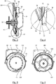
- la
figure 1 illustre une vue en perspective d'un semoir ; - la
figure 2 illustre une vue éclatée d'un dispositif de distribution de graines selon l'invention ; - la
figure 3 illustre une vue en coupe transversale du dispositif de lafigure 2 ; - la
figure 4 illustre une vue de détail de lafigure 3 ; - la
figure 5 illustre une vue de côté du dispositif de lafigure 3 sans le couvercle ; - la
figure 6 illustre une vue de côté de l'intérieur du tambour du dispositif de lafigure 3 ; - les
figures 7, 8, 9 et 10 illustrent des joints d'un dispositif selon l'invention ; - la
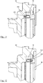
figure 11 illustre une vue partielle en coupe transversale du distributeur de graines de lafigure 3 ; - la
figure 12 illustre une vue partielle en coupe transversale d'une variante d'un distributeur de graines selon l'invention.
- the
figure 1 illustrates a perspective view of a planter; - the
figure 2 illustrates an exploded view of a seed distribution device according to the invention; - the
figure 3 illustrates a cross-sectional view of the device of thefigure 2 ; - the
figure 4 illustrates a detail view of thefigure 3 ; - the
figure 5 illustrates a side view of the device of thefigure 3 without the cover; - the
figure 6 illustrates a side view of the interior of the device drum of thefigure 3 ; - the
figures 7, 8, 9 and 10 illustrate seals of a device according to the invention; - the
figure 11 illustrates a partial cross-sectional view of the seed distributor of thefigure 3 ; - the
figure 12 illustrates a partial cross-sectional view of a variant of a seed distributor according to the invention.
On présente en relation avec les
Un tel dispositif de distribution de graines à l'unité comprend un boîtier destiné à être solidarisé de manière fixe à un élément semeur.Such a unit for distributing seeds comprises a housing intended to be fixedly secured to a sowing element.
Ce boîtier comprend un tambour 30 et un couvercle 31, fixes l'un par rapport à l'autre, et définissant ensemble une cavité intérieure.This housing comprises a
Un arbre d'entraînement 32 est monté mobile en rotation à travers le tambour 30. Une première extrémité 321 de l'arbre d'entraînement 32 s'étend à l'extérieur du tambour 30 alors qu'une deuxième extrémité 322 de l'arbre d'entraînement 32 s'étend à l'intérieur de la cavité.A
Un disque distributeur 33, traversé par une pluralité de trous d'aspiration de graines 331 ménagés de manière régulière à sa périphérie, est monté solidaire en rotation sur l'arbre d'entraînement 32 à l'intérieur de la cavité. Il y délimite, avec le tambour 30 et le couvercle 31, une chambre de dépression 34 et un réservoir de graines 35.A
L'arbre d'entraînement 32 comprend un épaulement 323 qui s'étend à l'intérieur de la chambre de distribution 34. Cet épaulement 323 peut être directement formé dans l'arbre 32 ou bien être rapporté sur celui-ci.The
Le disque distributeur 33 est plaqué contre l'épaulement 323.The
Le tambour 30 présente un orifice 300 de mise en dépression de la chambre de dépression 34 qui est destiné à être connecté avec un dispositif pour faire le vide telle qu'une turbine (non représentée).The
La forme du tambour 30 est choisie de manière telle qu'une portion 330 de la zone du disque 33 qui est traversée par les trous 331 s'étende en dehors de la chambre de dépression 34. Le contour du tambour 30 présente ainsi une encoche 301.The shape of the
Un disque agitateur à pales 36 est monté solidaire en rotation sur l'arbre à l'intérieur du réservoir 35.A
Dans un autre mode de réalisation, les pales pourront être soudées ou moulées directement sur le disque distributeur 33, dès lors que le disque est suffisamment rigide.In another embodiment, the blades can be welded or molded directly on the
Le disque distributeur 33 ne se déforme pas, étant suffisamment rigide en tant que tel et/ou étant suffisamment rigide du fait du disque agitateur à pales 36. Il ne peut ainsi pas être déformé sous l'effet de la dépression susceptible d'être créée dans la chambre de dépression 34.The
Le couvercle 31 définit avec le disque 33 une zone d'éjection des graines 37.The
Le dispositif comprend des moyens d'étanchéisation pour assurer l'étanchéité de la chambre de dépression 34.The device comprises sealing means for sealing the
Ces moyens d'étanchéisation comprennent un joint élastique 38 et un insert de frottement 39.These sealing means comprise an
Le joint élastique 38 est fixe par rapport au tambour 30. Dans ce mode de réalisation, il y est solidarisé à l'intérieur d'une gorge 302 ménagée à cet effet dans le contour périphérique du tambour 30 délimitant la chambre de dépression 34. Le joint 38 comprend une portion de solidarisation 383 prévue pour être insérée à force dans la gorge 302. Il pourra par exemple être :
- un joint ayant une ou plusieurs lèvres 380, tel que celui illustré à la
figure 8 ; - un joint à âme
pleine 382, tel que celui illustré à lafigure 9 ; - un joint à âme creuse 381, tel que celui illustré à la
figure 10 .
- a seal having one or
more lips 380, such as that illustrated infigure 8 ; - a
solid web gasket 382, such as the one shown infigure 9 ; - a
hollow core gasket 381, such as the one shown infigure 10 .
Ce joint sera préférentiellement réalisé dans une matière plastique telle qu'un élastomère.This seal will preferably be made from a plastic material such as an elastomer.
L'insert de frottement 39 est monté fixe par rapport au tambour 30. Il pourra par exemple y être solidarisé, de préférence en son centre, au moyen de vis ou autre. Il est interposé entre le joint élastique 38 et le disque distributeur 33. Sa forme est définie de manière telle qu'il n'obstrue pas les trous d'aspiration 331 du disque 33.The
L'insert de frottement 39 comprend une portion périphérique extérieure 391 en contact avec le joint 38, et une portion périphérique intérieure 392. L'insert présente une certaine élasticité en sorte que la portion périphérique extérieure 391 peut se déformer axialement par rapport à la portion périphérique intérieure 392 pour être plaquée contre le disque 33 sous l'effet du joint 38.The
En effet, la portion périphérique extérieure 391 est reliée à la portion périphérique intérieure 392 par des rayons pour donner une souplesse à la portion périphérique extérieure 391. La portion périphérique intérieure peut être fixée sur le boîtier à l'aide de moyens de fixation tels que des vis ou des arrêts en rotation ou autres, la fixation devant assurer que la portion périphérique intérieure 392 ne tourne pas avec le disque.Indeed, the outer
L'insert de frottement 39 est réalisé dans un matériau à faible coefficient de frottement. Il pourra par exemple s'agir d'une matière plastique, par exemple revêtue de téflon®.The
Le joint élastique 38 présente préférentiellement une raideur telle qu'il exerce sur l'insert de frottement un effort compris entre 10N et 100N par mètre linéaire pour une course de compression d'un millimètre.The
Du fait de son élasticité, le joint d'étanchéité élastique 38 maintient l'insert de frottement en appui contre le disque distributeur 33.Due to its elasticity, the
Un tel dispositif de distribution peut être mis en œuvre dans un élément semeur tels que ceux illustrés à la
La distribution de graines à l'unité est obtenue de la manière suivante.The distribution of seeds per unit is obtained as follows.
Alors que le semoir est déplacé à la surface du sol, l'arbre d'entraînement 32 est entraîné en rotation via des moyens d'entraînement prévus à cet effet. L'arbre d'entraînement 32 pourra par exemple porter une couronne 40 reliée par une chaîne à l'arbre d'un moteur ou à un arbre moteur (non représentés). Le disque distributeur 33 est alors entraîné en rotation proportionnellement à la vitesse d'avancement du semoir.While the drill is moved on the surface of the ground, the
Parallèlement, la turbine 20 est mise en œuvre pour générer une dépression à l'intérieur de la chambre de dépression 34. Des graines sont acheminées depuis les moyens de stockage de graines de l'élément semeur dans le réservoir 35. Du fait de la dépression régnant à l'intérieur de la chambre de dépression 34, les graines contenues dans le réservoir 35 sont aspirés et viennent se positionner une à une sur les trous d'aspiration 331 du disque distributeur 33 se trouvant en regard de la chambre de dépression 34.At the same time, the
Des moyens de sélection 41, connus en soit, peuvent éventuellement être mis en œuvre pour s'assurer que chaque trou 331 ne piège qu'une seule graine.Selection means 41, known per se, can optionally be implemented to ensure that each
Au fur et à mesure que le disque distributeur 33 tourne, les trous d'aspiration 331 sur chacun desquels une graine est positionnée s'étendent en dehors de la chambre de dépression 34 (portion 330). La graine n'est alors plus maintenue sur le trou 331 et tombe du disque 33 dans la zone d'éjection 37 en vue d'être acheminée dans le sillon préalablement creusé. Des moyens d'aide à l'éjection 42, connus en soit, peuvent également être mis en œuvre.As the
Compte-tenu notamment du rapport de vitesses entre la vitesse d'avancement du semoir et la vitesse de rotation du disque et compte-tenu du pas selon lequel les trous sont répartis sur le disque, les graines sont déposées à l'unité dans le sillon à intervalle régulier.Taking into account in particular the speed ratio between the forward speed of the seeder and the speed of rotation of the disc and taking into account the pitch according to which the holes are distributed on the disc, the seeds are deposited individually in the furrow at regular intervals.
Du fait de sa raideur ou de son association avec un agitateur, le disque distributeur 33 ne se déforme pas sous l'effet de la dépression générée à l'intérieur de la chambre de dépression 34. Il n'est donc pas plaqué contre l'insert de frottement ce qui limite la friction.Due to its stiffness or its association with an agitator, the
Du fait de son élasticité, le joint 38 imprime à l'insert de frottement 39 un effort qui tend à plaquer et maintenir celui-ci contre le disque 33. On assure ainsi une parfaite étanchéité de la chambre de dépression 34 sans pour autant générer un effort de friction important entre l'insert de frottement 39 et le disque distributeur 33. Ce niveau de friction dépend de la raideur du joint 38. La raideur de celui-ci est donc choisie de manière telle que l'étanchéité de la chambre de dépression soit assurée en générant une friction la plus faible possible entre le disque et l'insert.Due to its elasticity, the
La technique selon l'invention permet ainsi d'assurer une parfaite étanchéité de la chambre de dépression et par conséquent une distribution optimisée des graines, tout en limitant le dimensionnement des moyens moteurs mis en œuvre pour animer le distributeur et en réduisant la fréquence des campagnes de maintenance.The technique according to the invention thus makes it possible to ensure perfect sealing of the vacuum chamber and consequently an optimized distribution of the seeds, while limiting the sizing of the motor means used to drive the distributor and by reducing the frequency of campaigns. of maintenance.
La
La structure du distributeur de graines selon cette variante est identique à celle du distributeur de graines selon le mode de réalisation qui vient d'être décrit, à ceci près que le joint élastique 38 n'est plus solidaire du tambour 30. Il est au contraire solidaire de l'insert de frottement 39.The structure of the seed distributor according to this variant is identical to that of the seed distributor according to the embodiment which has just been described, except that the
Dans le mode de réalisation de la
Dans des variantes, le joint 38 pourra être solidarisé à l'insert de frottement 39 par collage, par surmoulage ou tout autre technique de solidarisation adaptée.In variants, the
La mise en œuvre de ce mode de réalisation permet de faciliter la maintenance du distributeur de graines. En effet, l'opérateur en charge de la maintenance doit démonter seulement l'insert de frottement qui porte le joint pour remplacer l'ensemble insert/joint usagé par un neuf plutôt que de démonter et de remplacer d'une part l'insert de frottement et d'autre part le joint.The implementation of this embodiment makes it possible to facilitate the maintenance of the seed distributor. In fact, the operator in charge of maintenance must only remove the friction insert which carries the seal to replace the worn insert / seal assembly with a new one rather than dismantling and replacing on the one hand the friction insert. friction and on the other hand the seal.
Du fait de son élasticité, le joint 38, en appui contre le tambour 30, agit contre l'insert de frottement 39 pour le plaquer contre le disque 33 avec un niveau de friction juste suffisant pour garantir l'étanchéité de la chambre de dépression 34. On limiter ainsi l'usure et la fréquence des campagnes de maintenance tout en assurant une étanchéité efficace de la chambre de dépression et par conséquent une distribution optimale des graines.Due to its elasticity, the
Dans une variante, l'insert de frottement pourra ne pas être solidarisé au tambour. Il pourra au contraire être monté flottant sur le tambour de manière telle qui soit lié à celui-ci en rotation mais qu'il puisse de déplacer par rapport à celui-ci le long de son axe longitudinal. L'insert de frottement pourra être traversé par des trous longitudinaux et le tambour présenter des axes s'étendant le long d'axes parallèles à l'axe de l'arbre d'entrainement. Ces axes seront insérés dans les trous de l'insert de frottement bloquant celui-ci en rotation mais pas en translation.In a variant, the friction insert may not be secured to the drum. On the contrary, it could be mounted floating on the drum in such a way that it is linked to the latter in rotation but that it can move relative to the latter along its longitudinal axis. The friction insert may be traversed by longitudinal holes and the drum may have axes extending along axes parallel to the axis of the drive shaft. These pins will be inserted into the holes of the friction insert blocking it in rotation but not in translation.
Claims (10)
- Device for dispensing seeds individually, said device comprising:- a drum (30) intended to be attached fixedly to a seeder (10);- a cover (31) that is fixed with respect to said drum (30) and with said drum (30) defines an interior cavity;- a drive shaft (32) mounted with the ability to rotate through said drum (30);- a distributor disc (33) through which there passes a plurality of seed suction holes (331) formed uniformly at the periphery of said disc (33), said disc (33) being mounted on said shaft (32) to rotate as one with same inside said cavity so that there it delimits, with said drum (30) and said cover (31) a vacuum chamber (34) and a seed reservoir (35), a portion (330) of the region of said disc (33) through which said holes (331) pass extending outside of said vacuum chamber (34),- means for providing the sealing of said vacuum chamber (34) between said drum (30) and said disc (33) ;
said means for providing sealing comprising a rubbing insert (39) mounted with the inability to rotate with respect to said drum (30) against the periphery of said disc (33), and an elastic seal (38) mounted with the inability to rotate between said drum (31) and said rubbing insert (39), said elastic seal (38) keeping said rubbing insert (39) pressed against said disc (33), characterized in that the rubbing insert (39) forms a replaceable wearing component, and in that said seal (38) has a stiffness such that it applies to said rubbing insert (39) a force of between 10N and 100N per linear metre for a compression travel of one millimetre. - Device according to Claim 1, characterized in that said rubbing insert (39) comprises an exterior peripheral portion (391) in contact with said seal (38), and an interior peripheral portion (392), said exterior peripheral portion (391) being able to deform axially with respect to said interior peripheral portion (392).
- Device according to either one of Claims 1 and 2, characterized in that said shaft (32) comprises a shoulder (323) situated inside said vacuum chamber (34), said disc (33) coming to bear against said shoulder (323).
- Device according to any one of Claims 1 to 3, characterized in that said rubbing insert (39) is made from a material with a low coefficient of friction.
- Device according to any one of Claims 1 to 4, characterized in that said seal (38) belongs to the group comprising at least:- lip seals with one or more lips;- hollow seals;- solid seals.
- Device according to any one of Claims 1 to 5, characterized in that said seal (38) is secured to said drum (30).
- Device according to any one of Claims 1 to 5, characterized in that said seal (38) is secured to said rubbing insert (39).
- Device according to Claim 7, characterized in that said seal (38) is secured to said rubbing insert (39) by bonding, overmoulding or clipping into a groove (393) of complementary shape formed in said rubbing insert (39).
- Seeding element (11) comprising a distribution device according to any one of Claims 1 to 8.
- Seeder (10) comprising at least one seeding element (17) according to Claim 9.
Priority Applications (2)
| Application Number | Priority Date | Filing Date | Title |
|---|---|---|---|
| PL14170080T PL2810546T3 (en) | 2013-06-04 | 2014-05-27 | Device for dispensing individual seeds |
| US14/295,995 US9485902B2 (en) | 2013-06-04 | 2014-06-04 | Device for dispensing seeds singly |
Applications Claiming Priority (1)
| Application Number | Priority Date | Filing Date | Title |
|---|---|---|---|
| FR1355138A FR3006145B1 (en) | 2013-06-04 | 2013-06-04 | DEVICE FOR DISTRIBUTING SEEDS TO THE UNIT |
Publications (2)
| Publication Number | Publication Date |
|---|---|
| EP2810546A1 EP2810546A1 (en) | 2014-12-10 |
| EP2810546B1 true EP2810546B1 (en) | 2020-10-14 |
Family
ID=48980110
Family Applications (1)
| Application Number | Title | Priority Date | Filing Date |
|---|---|---|---|
| EP14170080.7A Active EP2810546B1 (en) | 2013-06-04 | 2014-05-27 | Device for dispensing individual seeds |
Country Status (8)
| Country | Link |
|---|---|
| US (1) | US9485902B2 (en) |
| EP (1) | EP2810546B1 (en) |
| DK (1) | DK2810546T3 (en) |
| ES (1) | ES2838688T3 (en) |
| FR (1) | FR3006145B1 (en) |
| HU (1) | HUE052825T2 (en) |
| PL (1) | PL2810546T3 (en) |
| PT (1) | PT2810546T (en) |
Families Citing this family (4)
| Publication number | Priority date | Publication date | Assignee | Title |
|---|---|---|---|---|
| AR098148A1 (en) * | 2014-05-22 | 2016-05-04 | Alberto Gentili Jorge | SEED DISTRIBUTOR DEVICE BY DIRECT DRIVING |
| IT201700082167A1 (en) * | 2017-07-19 | 2019-01-19 | Matermacc S P A | DISTRIBUTOR DEVICE OF MATERIAL FOR AGRICULTURAL MACHINES |
| CN111511190B (en) | 2017-11-10 | 2023-05-02 | 马斯奇奥盖斯帕多股份有限公司 | Seeding element for precision agricultural seeding machine and seeding machine comprising such element |
| CN107593032A (en) * | 2017-11-15 | 2018-01-19 | 石河子市华农种子机械制造有限公司 | Drum-type seed pelleting machine |
Family Cites Families (4)
| Publication number | Priority date | Publication date | Assignee | Title |
|---|---|---|---|---|
| CA1235337A (en) * | 1983-10-31 | 1988-04-19 | Jay H. Olson | Flexible vacuum seal |
| GB9414211D0 (en) * | 1994-07-14 | 1994-08-31 | Webb Stanhay Ltd | Seed dispensing mechanism |
| US7866525B2 (en) * | 2006-10-06 | 2011-01-11 | Tyco Healthcare Group Lp | Surgical instrument having a plastic surface |
| SE535698C2 (en) * | 2011-03-09 | 2012-11-13 | Vaederstad Verken Ab | Sealing strip and seed housing for a seed drill, as well as seed drill comprising such seed housing |
-
2013
- 2013-06-04 FR FR1355138A patent/FR3006145B1/en active Active
-
2014
- 2014-05-27 EP EP14170080.7A patent/EP2810546B1/en active Active
- 2014-05-27 ES ES14170080T patent/ES2838688T3/en active Active
- 2014-05-27 HU HUE14170080A patent/HUE052825T2/en unknown
- 2014-05-27 PL PL14170080T patent/PL2810546T3/en unknown
- 2014-05-27 PT PT141700807T patent/PT2810546T/en unknown
- 2014-05-27 DK DK14170080.7T patent/DK2810546T3/en active
- 2014-06-04 US US14/295,995 patent/US9485902B2/en active Active
Non-Patent Citations (1)
| Title |
|---|
| None * |
Also Published As
| Publication number | Publication date |
|---|---|
| FR3006145B1 (en) | 2015-06-26 |
| PL2810546T3 (en) | 2021-04-06 |
| HUE052825T2 (en) | 2021-05-28 |
| US9485902B2 (en) | 2016-11-08 |
| EP2810546A1 (en) | 2014-12-10 |
| ES2838688T3 (en) | 2021-07-02 |
| US20140352588A1 (en) | 2014-12-04 |
| DK2810546T3 (en) | 2021-01-11 |
| PT2810546T (en) | 2021-01-18 |
| FR3006145A1 (en) | 2014-12-05 |
Similar Documents
| Publication | Publication Date | Title |
|---|---|---|
| EP2810546B1 (en) | Device for dispensing individual seeds | |
| FR2961058A1 (en) | Single-grain seeder for culturing e.g. corn, has depression chamber sealed by dispensing disk, and exerting unit exerting constraint on obturating disk to maintain obturating disk in support against dispensing disk along angular portion | |
| CA2668531C (en) | Semi-hollow tire and wheel rim for use therewith, specifically intended for agricultural machines | |
| CA2848707C (en) | Semi-hollow tire for agricultural machines, specifically for sowing machines | |
| EP0914763B1 (en) | Disc coulter for seed drills | |
| EP3017967A1 (en) | Agricultural tyre | |
| EP0046709A1 (en) | Distributing device for pneumatic precision drill | |
| FR2991550A1 (en) | PNEUMATIC HEATER COMPRISING MEANS FOR DAMPING AND / OR DEVIATION OF AIR FLOW EXTRACTED FROM TURBINE | |
| FR2905558A1 (en) | Working tool i.e. plowshare, for e.g. reversible plow in agricultural machine, has groove, and wear out part and/or point fixed on tool using wedge housed in groove and fixation device inserted in slot that is provided in wedge | |
| FR2964293A1 (en) | ROLL ASSEMBLY FOR AGRICULTURAL MACHINERY | |
| CA2911769A1 (en) | Improved agricultural tire | |
| EP3834594A1 (en) | Scraping gauge wheel for seeder | |
| FR3083960A1 (en) | SEEDER COUPLABLE TO A TRACTOR AND INTEGRATED SOIL WORKING MACHINE | |
| FR2943491A1 (en) | LABOR DISC AND LABOR DEVICE COMPRISING AT LEAST ONE TRAIN EQUIPPED WITH SUCH A DISK | |
| FR2979178A1 (en) | AGRICULTURAL SOIL TILLING APPARATUS, IN PARTICULAR A SEEDER EQUIPPED WITH DISCOIDAL SOCKS OF SOWING | |
| CA2381044A1 (en) | Device for setting a plastic film or the like, in particular for agricultural purposes | |
| EP0392890B1 (en) | Silage cutter and rotary cutter for forage, especially silage | |
| FR2993749A1 (en) | HERISSON FOR SPREADER | |
| EP0682854B1 (en) | An agricultural soil working roller and agricultural machine using such a roller | |
| FR2989746A1 (en) | FLEXIBLE TRANSMISSION DEVICE COMPRISING RIGIDIFICATION MEANS ALONG A FIRST DIRECTION AND NOT ALONG A SECOND DIRECTION | |
| FR2689725A1 (en) | Agricultural machine, for burying liquid silage - has large furrowing disc, spherical in shape, with flattened edge, and silage feed tube, which has adjustable feed position | |
| FR2480065A1 (en) | Seed drill with conveyor belt - has belt driven from land-wheel delivering upwards from hopper into spout | |
| FR3134947A1 (en) | Device for accelerating at least one granular element, preferably a seed | |
| CA3152037A1 (en) | Farm machinery disc insert and associated farm machinery | |
| FR2943490A1 (en) | LABOR DISC AND LABOR DEVICE COMPRISING AT LEAST ONE TRAIN EQUIPPED WITH SUCH A DISK |
Legal Events
| Date | Code | Title | Description |
|---|---|---|---|
| PUAI | Public reference made under article 153(3) epc to a published international application that has entered the european phase |
Free format text: ORIGINAL CODE: 0009012 |
|
| 17P | Request for examination filed |
Effective date: 20140527 |
|
| AK | Designated contracting states |
Kind code of ref document: A1 Designated state(s): AL AT BE BG CH CY CZ DE DK EE ES FI FR GB GR HR HU IE IS IT LI LT LU LV MC MK MT NL NO PL PT RO RS SE SI SK SM TR |
|
| AX | Request for extension of the european patent |
Extension state: BA ME |
|
| R17P | Request for examination filed (corrected) |
Effective date: 20150311 |
|
| RBV | Designated contracting states (corrected) |
Designated state(s): AL AT BE BG CH CY CZ DE DK EE ES FI FR GB GR HR HU IE IS IT LI LT LU LV MC MK MT NL NO PL PT RO RS SE SI SK SM TR |
|
| STAA | Information on the status of an ep patent application or granted ep patent |
Free format text: STATUS: EXAMINATION IS IN PROGRESS |
|
| 17Q | First examination report despatched |
Effective date: 20190625 |
|
| GRAP | Despatch of communication of intention to grant a patent |
Free format text: ORIGINAL CODE: EPIDOSNIGR1 |
|
| STAA | Information on the status of an ep patent application or granted ep patent |
Free format text: STATUS: GRANT OF PATENT IS INTENDED |
|
| INTG | Intention to grant announced |
Effective date: 20200430 |
|
| GRAS | Grant fee paid |
Free format text: ORIGINAL CODE: EPIDOSNIGR3 |
|
| GRAA | (expected) grant |
Free format text: ORIGINAL CODE: 0009210 |
|
| STAA | Information on the status of an ep patent application or granted ep patent |
Free format text: STATUS: THE PATENT HAS BEEN GRANTED |
|
| AK | Designated contracting states |
Kind code of ref document: B1 Designated state(s): AL AT BE BG CH CY CZ DE DK EE ES FI FR GB GR HR HU IE IS IT LI LT LU LV MC MK MT NL NO PL PT RO RS SE SI SK SM TR |
|
| REG | Reference to a national code |
Ref country code: GB Ref legal event code: FG4D Free format text: NOT ENGLISH |
|
| REG | Reference to a national code |
Ref country code: AT Ref legal event code: REF Ref document number: 1322633 Country of ref document: AT Kind code of ref document: T Effective date: 20201015 Ref country code: CH Ref legal event code: EP |
|
| REG | Reference to a national code |
Ref country code: DE Ref legal event code: R096 Ref document number: 602014071166 Country of ref document: DE |
|
| REG | Reference to a national code |
Ref country code: IE Ref legal event code: FG4D Free format text: LANGUAGE OF EP DOCUMENT: FRENCH |
|
| REG | Reference to a national code |
Ref country code: NL Ref legal event code: FP |
|
| REG | Reference to a national code |
Ref country code: DK Ref legal event code: T3 Effective date: 20210104 |
|
| REG | Reference to a national code |
Ref country code: PT Ref legal event code: SC4A Ref document number: 2810546 Country of ref document: PT Date of ref document: 20210118 Kind code of ref document: T Free format text: AVAILABILITY OF NATIONAL TRANSLATION Effective date: 20210112 |
|
| PG25 | Lapsed in a contracting state [announced via postgrant information from national office to epo] |
Ref country code: NO Free format text: LAPSE BECAUSE OF FAILURE TO SUBMIT A TRANSLATION OF THE DESCRIPTION OR TO PAY THE FEE WITHIN THE PRESCRIBED TIME-LIMIT Effective date: 20210114 Ref country code: RS Free format text: LAPSE BECAUSE OF FAILURE TO SUBMIT A TRANSLATION OF THE DESCRIPTION OR TO PAY THE FEE WITHIN THE PRESCRIBED TIME-LIMIT Effective date: 20201014 Ref country code: FI Free format text: LAPSE BECAUSE OF FAILURE TO SUBMIT A TRANSLATION OF THE DESCRIPTION OR TO PAY THE FEE WITHIN THE PRESCRIBED TIME-LIMIT Effective date: 20201014 Ref country code: GR Free format text: LAPSE BECAUSE OF FAILURE TO SUBMIT A TRANSLATION OF THE DESCRIPTION OR TO PAY THE FEE WITHIN THE PRESCRIBED TIME-LIMIT Effective date: 20210115 |
|
| REG | Reference to a national code |
Ref country code: LT Ref legal event code: MG4D |
|
| REG | Reference to a national code |
Ref country code: HU Ref legal event code: AG4A Ref document number: E052825 Country of ref document: HU |
|
| PG25 | Lapsed in a contracting state [announced via postgrant information from national office to epo] |
Ref country code: LV Free format text: LAPSE BECAUSE OF FAILURE TO SUBMIT A TRANSLATION OF THE DESCRIPTION OR TO PAY THE FEE WITHIN THE PRESCRIBED TIME-LIMIT Effective date: 20201014 Ref country code: IS Free format text: LAPSE BECAUSE OF FAILURE TO SUBMIT A TRANSLATION OF THE DESCRIPTION OR TO PAY THE FEE WITHIN THE PRESCRIBED TIME-LIMIT Effective date: 20210214 Ref country code: SE Free format text: LAPSE BECAUSE OF FAILURE TO SUBMIT A TRANSLATION OF THE DESCRIPTION OR TO PAY THE FEE WITHIN THE PRESCRIBED TIME-LIMIT Effective date: 20201014 Ref country code: BG Free format text: LAPSE BECAUSE OF FAILURE TO SUBMIT A TRANSLATION OF THE DESCRIPTION OR TO PAY THE FEE WITHIN THE PRESCRIBED TIME-LIMIT Effective date: 20210114 |
|
| PG25 | Lapsed in a contracting state [announced via postgrant information from national office to epo] |
Ref country code: HR Free format text: LAPSE BECAUSE OF FAILURE TO SUBMIT A TRANSLATION OF THE DESCRIPTION OR TO PAY THE FEE WITHIN THE PRESCRIBED TIME-LIMIT Effective date: 20201014 |
|
| REG | Reference to a national code |
Ref country code: ES Ref legal event code: FG2A Ref document number: 2838688 Country of ref document: ES Kind code of ref document: T3 Effective date: 20210702 |
|
| REG | Reference to a national code |
Ref country code: DE Ref legal event code: R097 Ref document number: 602014071166 Country of ref document: DE |
|
| PG25 | Lapsed in a contracting state [announced via postgrant information from national office to epo] |
Ref country code: SK Free format text: LAPSE BECAUSE OF FAILURE TO SUBMIT A TRANSLATION OF THE DESCRIPTION OR TO PAY THE FEE WITHIN THE PRESCRIBED TIME-LIMIT Effective date: 20201014 Ref country code: RO Free format text: LAPSE BECAUSE OF FAILURE TO SUBMIT A TRANSLATION OF THE DESCRIPTION OR TO PAY THE FEE WITHIN THE PRESCRIBED TIME-LIMIT Effective date: 20201014 Ref country code: LT Free format text: LAPSE BECAUSE OF FAILURE TO SUBMIT A TRANSLATION OF THE DESCRIPTION OR TO PAY THE FEE WITHIN THE PRESCRIBED TIME-LIMIT Effective date: 20201014 Ref country code: EE Free format text: LAPSE BECAUSE OF FAILURE TO SUBMIT A TRANSLATION OF THE DESCRIPTION OR TO PAY THE FEE WITHIN THE PRESCRIBED TIME-LIMIT Effective date: 20201014 Ref country code: SM Free format text: LAPSE BECAUSE OF FAILURE TO SUBMIT A TRANSLATION OF THE DESCRIPTION OR TO PAY THE FEE WITHIN THE PRESCRIBED TIME-LIMIT Effective date: 20201014 |
|
| PLBE | No opposition filed within time limit |
Free format text: ORIGINAL CODE: 0009261 |
|
| STAA | Information on the status of an ep patent application or granted ep patent |
Free format text: STATUS: NO OPPOSITION FILED WITHIN TIME LIMIT |
|
| 26N | No opposition filed |
Effective date: 20210715 |
|
| PG25 | Lapsed in a contracting state [announced via postgrant information from national office to epo] |
Ref country code: AL Free format text: LAPSE BECAUSE OF FAILURE TO SUBMIT A TRANSLATION OF THE DESCRIPTION OR TO PAY THE FEE WITHIN THE PRESCRIBED TIME-LIMIT Effective date: 20201014 |
|
| PG25 | Lapsed in a contracting state [announced via postgrant information from national office to epo] |
Ref country code: SI Free format text: LAPSE BECAUSE OF FAILURE TO SUBMIT A TRANSLATION OF THE DESCRIPTION OR TO PAY THE FEE WITHIN THE PRESCRIBED TIME-LIMIT Effective date: 20201014 |
|
| PG25 | Lapsed in a contracting state [announced via postgrant information from national office to epo] |
Ref country code: LU Free format text: LAPSE BECAUSE OF NON-PAYMENT OF DUE FEES Effective date: 20210527 Ref country code: MC Free format text: LAPSE BECAUSE OF FAILURE TO SUBMIT A TRANSLATION OF THE DESCRIPTION OR TO PAY THE FEE WITHIN THE PRESCRIBED TIME-LIMIT Effective date: 20201014 |
|
| PG25 | Lapsed in a contracting state [announced via postgrant information from national office to epo] |
Ref country code: IS Free format text: LAPSE BECAUSE OF FAILURE TO SUBMIT A TRANSLATION OF THE DESCRIPTION OR TO PAY THE FEE WITHIN THE PRESCRIBED TIME-LIMIT Effective date: 20210214 |
|
| REG | Reference to a national code |
Ref country code: AT Ref legal event code: UEP Ref document number: 1322633 Country of ref document: AT Kind code of ref document: T Effective date: 20201014 |
|
| PG25 | Lapsed in a contracting state [announced via postgrant information from national office to epo] |
Ref country code: CY Free format text: LAPSE BECAUSE OF FAILURE TO SUBMIT A TRANSLATION OF THE DESCRIPTION OR TO PAY THE FEE WITHIN THE PRESCRIBED TIME-LIMIT Effective date: 20201014 |
|
| PGFP | Annual fee paid to national office [announced via postgrant information from national office to epo] |
Ref country code: PT Payment date: 20230503 Year of fee payment: 10 Ref country code: NL Payment date: 20230526 Year of fee payment: 10 Ref country code: IT Payment date: 20230519 Year of fee payment: 10 Ref country code: IE Payment date: 20230529 Year of fee payment: 10 Ref country code: FR Payment date: 20230525 Year of fee payment: 10 Ref country code: ES Payment date: 20230601 Year of fee payment: 10 Ref country code: DK Payment date: 20230530 Year of fee payment: 10 Ref country code: DE Payment date: 20230419 Year of fee payment: 10 Ref country code: CZ Payment date: 20230510 Year of fee payment: 10 Ref country code: CH Payment date: 20230610 Year of fee payment: 10 |
|
| PGFP | Annual fee paid to national office [announced via postgrant information from national office to epo] |
Ref country code: TR Payment date: 20230510 Year of fee payment: 10 Ref country code: PL Payment date: 20230504 Year of fee payment: 10 Ref country code: HU Payment date: 20230511 Year of fee payment: 10 Ref country code: AT Payment date: 20230504 Year of fee payment: 10 |
|
| PGFP | Annual fee paid to national office [announced via postgrant information from national office to epo] |
Ref country code: BE Payment date: 20230529 Year of fee payment: 10 |
|
| PGFP | Annual fee paid to national office [announced via postgrant information from national office to epo] |
Ref country code: GB Payment date: 20230529 Year of fee payment: 10 |
|
| PG25 | Lapsed in a contracting state [announced via postgrant information from national office to epo] |
Ref country code: MK Free format text: LAPSE BECAUSE OF FAILURE TO SUBMIT A TRANSLATION OF THE DESCRIPTION OR TO PAY THE FEE WITHIN THE PRESCRIBED TIME-LIMIT Effective date: 20201014 |