EP2810366B1 - Method and apparatus for monitoring the short-circuiting switching device of a three-phase motor - Google Patents
Method and apparatus for monitoring the short-circuiting switching device of a three-phase motor Download PDFInfo
- Publication number
- EP2810366B1 EP2810366B1 EP13714180.0A EP13714180A EP2810366B1 EP 2810366 B1 EP2810366 B1 EP 2810366B1 EP 13714180 A EP13714180 A EP 13714180A EP 2810366 B1 EP2810366 B1 EP 2810366B1
- Authority
- EP
- European Patent Office
- Prior art keywords
- motor
- short
- circuiting
- currents
- voltages
- Prior art date
- Legal status (The legal status is an assumption and is not a legal conclusion. Google has not performed a legal analysis and makes no representation as to the accuracy of the status listed.)
- Active
Links
- 238000000034 method Methods 0.000 title claims description 32
- 238000012544 monitoring process Methods 0.000 title claims description 19
- 238000012360 testing method Methods 0.000 claims description 35
- 238000005259 measurement Methods 0.000 claims description 7
- 238000009826 distribution Methods 0.000 claims description 6
- 238000004804 winding Methods 0.000 claims description 4
- 230000004913 activation Effects 0.000 claims 1
- 230000001172 regenerating effect Effects 0.000 claims 1
- 238000001514 detection method Methods 0.000 description 3
- 239000004020 conductor Substances 0.000 description 2
- 230000001360 synchronised effect Effects 0.000 description 2
- 230000001010 compromised effect Effects 0.000 description 1
- 230000006735 deficit Effects 0.000 description 1
- 230000001419 dependent effect Effects 0.000 description 1
- 238000010586 diagram Methods 0.000 description 1
- 230000000694 effects Effects 0.000 description 1
- 238000011156 evaluation Methods 0.000 description 1
- 238000010998 test method Methods 0.000 description 1
- 230000001960 triggered effect Effects 0.000 description 1
Images


Classifications
-
- G—PHYSICS
- G01—MEASURING; TESTING
- G01R—MEASURING ELECTRIC VARIABLES; MEASURING MAGNETIC VARIABLES
- G01R31/00—Arrangements for testing electric properties; Arrangements for locating electric faults; Arrangements for electrical testing characterised by what is being tested not provided for elsewhere
- G01R31/40—Testing power supplies
-
- H—ELECTRICITY
- H02—GENERATION; CONVERSION OR DISTRIBUTION OF ELECTRIC POWER
- H02P—CONTROL OR REGULATION OF ELECTRIC MOTORS, ELECTRIC GENERATORS OR DYNAMO-ELECTRIC CONVERTERS; CONTROLLING TRANSFORMERS, REACTORS OR CHOKE COILS
- H02P3/00—Arrangements for stopping or slowing electric motors, generators, or dynamo-electric converters
- H02P3/06—Arrangements for stopping or slowing electric motors, generators, or dynamo-electric converters for stopping or slowing an individual dynamo-electric motor or dynamo-electric converter
- H02P3/18—Arrangements for stopping or slowing electric motors, generators, or dynamo-electric converters for stopping or slowing an individual dynamo-electric motor or dynamo-electric converter for stopping or slowing an ac motor
- H02P3/22—Arrangements for stopping or slowing electric motors, generators, or dynamo-electric converters for stopping or slowing an individual dynamo-electric motor or dynamo-electric converter for stopping or slowing an ac motor by short-circuit or resistive braking
-
- B—PERFORMING OPERATIONS; TRANSPORTING
- B60—VEHICLES IN GENERAL
- B60L—PROPULSION OF ELECTRICALLY-PROPELLED VEHICLES; SUPPLYING ELECTRIC POWER FOR AUXILIARY EQUIPMENT OF ELECTRICALLY-PROPELLED VEHICLES; ELECTRODYNAMIC BRAKE SYSTEMS FOR VEHICLES IN GENERAL; MAGNETIC SUSPENSION OR LEVITATION FOR VEHICLES; MONITORING OPERATING VARIABLES OF ELECTRICALLY-PROPELLED VEHICLES; ELECTRIC SAFETY DEVICES FOR ELECTRICALLY-PROPELLED VEHICLES
- B60L3/00—Electric devices on electrically-propelled vehicles for safety purposes; Monitoring operating variables, e.g. speed, deceleration or energy consumption
- B60L3/0023—Detecting, eliminating, remedying or compensating for drive train abnormalities, e.g. failures within the drive train
- B60L3/0076—Detecting, eliminating, remedying or compensating for drive train abnormalities, e.g. failures within the drive train relating to braking
-
- H—ELECTRICITY
- H02—GENERATION; CONVERSION OR DISTRIBUTION OF ELECTRIC POWER
- H02P—CONTROL OR REGULATION OF ELECTRIC MOTORS, ELECTRIC GENERATORS OR DYNAMO-ELECTRIC CONVERTERS; CONTROLLING TRANSFORMERS, REACTORS OR CHOKE COILS
- H02P29/00—Arrangements for regulating or controlling electric motors, appropriate for both AC and DC motors
- H02P29/02—Providing protection against overload without automatic interruption of supply
- H02P29/024—Detecting a fault condition, e.g. short circuit, locked rotor, open circuit or loss of load
- H02P29/0241—Detecting a fault condition, e.g. short circuit, locked rotor, open circuit or loss of load the fault being an overvoltage
-
- G—PHYSICS
- G01—MEASURING; TESTING
- G01R—MEASURING ELECTRIC VARIABLES; MEASURING MAGNETIC VARIABLES
- G01R31/00—Arrangements for testing electric properties; Arrangements for locating electric faults; Arrangements for electrical testing characterised by what is being tested not provided for elsewhere
- G01R31/327—Testing of circuit interrupters, switches or circuit-breakers
- G01R31/3277—Testing of circuit interrupters, switches or circuit-breakers of low voltage devices, e.g. domestic or industrial devices, such as motor protections, relays, rotation switches
-
- G—PHYSICS
- G01—MEASURING; TESTING
- G01R—MEASURING ELECTRIC VARIABLES; MEASURING MAGNETIC VARIABLES
- G01R31/00—Arrangements for testing electric properties; Arrangements for locating electric faults; Arrangements for electrical testing characterised by what is being tested not provided for elsewhere
- G01R31/34—Testing dynamo-electric machines
- G01R31/343—Testing dynamo-electric machines in operation
-
- H—ELECTRICITY
- H02—GENERATION; CONVERSION OR DISTRIBUTION OF ELECTRIC POWER
- H02H—EMERGENCY PROTECTIVE CIRCUIT ARRANGEMENTS
- H02H7/00—Emergency protective circuit arrangements specially adapted for specific types of electric machines or apparatus or for sectionalised protection of cable or line systems, and effecting automatic switching in the event of an undesired change from normal working conditions
- H02H7/10—Emergency protective circuit arrangements specially adapted for specific types of electric machines or apparatus or for sectionalised protection of cable or line systems, and effecting automatic switching in the event of an undesired change from normal working conditions for converters; for rectifiers
- H02H7/12—Emergency protective circuit arrangements specially adapted for specific types of electric machines or apparatus or for sectionalised protection of cable or line systems, and effecting automatic switching in the event of an undesired change from normal working conditions for converters; for rectifiers for static converters or rectifiers
- H02H7/1216—Emergency protective circuit arrangements specially adapted for specific types of electric machines or apparatus or for sectionalised protection of cable or line systems, and effecting automatic switching in the event of an undesired change from normal working conditions for converters; for rectifiers for static converters or rectifiers for AC-AC converters
-
- H—ELECTRICITY
- H02—GENERATION; CONVERSION OR DISTRIBUTION OF ELECTRIC POWER
- H02P—CONTROL OR REGULATION OF ELECTRIC MOTORS, ELECTRIC GENERATORS OR DYNAMO-ELECTRIC CONVERTERS; CONTROLLING TRANSFORMERS, REACTORS OR CHOKE COILS
- H02P2207/00—Indexing scheme relating to controlling arrangements characterised by the type of motor
- H02P2207/05—Synchronous machines, e.g. with permanent magnets or DC excitation
-
- Y—GENERAL TAGGING OF NEW TECHNOLOGICAL DEVELOPMENTS; GENERAL TAGGING OF CROSS-SECTIONAL TECHNOLOGIES SPANNING OVER SEVERAL SECTIONS OF THE IPC; TECHNICAL SUBJECTS COVERED BY FORMER USPC CROSS-REFERENCE ART COLLECTIONS [XRACs] AND DIGESTS
- Y02—TECHNOLOGIES OR APPLICATIONS FOR MITIGATION OR ADAPTATION AGAINST CLIMATE CHANGE
- Y02T—CLIMATE CHANGE MITIGATION TECHNOLOGIES RELATED TO TRANSPORTATION
- Y02T10/00—Road transport of goods or passengers
- Y02T10/60—Other road transportation technologies with climate change mitigation effect
- Y02T10/64—Electric machine technologies in electromobility
Definitions
- the invention relates to a method for monitoring the short circuit switching device of a three-phase motor for driving vehicles, which is fed from a DC voltage source via a controlled inverter, wherein the controlled by a control logic short circuit switching device is connected to the inputs of the motor and the motor currents and / or motor voltages are measured.
- Short-circuit contactors used for this purpose are thus a safety device which is triggered when a shutdown condition occurs and thus brings about the safe state of the three-phase motor by means of a "three-phase short circuit” (and thus virtually torque-free rotation).
- the monitoring of the short circuit switching device is when using the electric motor in a safety-relevant application to a special role, since the device that can bring about the safe state, namely the short-circuit contactors, must be checked at regular intervals for their effectiveness. These checks must be carried out at appropriate times, as they interrupt the normal operation of the electric motor, and they should be able to be carried out easily and reliably with existing equipment, ideally at the time of switch-on.
- the safety aspects apply in particular for use in electric and hybrid vehicles.
- EP 2 079 159 A2 is a drive device has become known, which has a dynamic brake circuit, wherein a synchronous machine via electrical resistances converts braking power and is therefore suitable to perform delay work.
- short-circuit contactors in vehicles can be checked regularly and with simple, without existing means, without any apparent for the user impairment of driving behavior, for example, by the emergence of undesirable engine torque, occurs or breaks would be required.
- the evaluation will generally include an indication to the driver and / or storage and / or intervention in the driving management of the vehicle.
- test patterns are generated and supplied to the motor with the aid of the controlled converter during a test phase, wherein only those power switches are activated which are required for the operation of two motor phases, wherein one phase remains de-energized and the Amperage is dimensioned by the remaining two phases during the test pattern so that the motor generates almost no torque, during the test pattern, the currents and / or voltages measured at the motor phases and the redistribution of currents and / or voltages at closing or opening the short-circuit contacts are detected and evaluated.
- each of the motor phases is so slightly different from each other switching patterns applied that defined, small voltage differences between the motor phases occur and the motor supplies almost no torque and measured during the test pattern, the currents and / or voltages at the motor phases and the Redistribution of currents and / or voltages when closing or opening the short-circuit contacts is detected and evaluated.
- Another advantageous variant of the method provides, it is carried out with a rotating motor, but in a speed range in which no passive recuperation occurs over the switching paths of the inverter bridging diodes.
- the circuit breakers of the inverter be inactivated, which measured when temporarily closing the short-circuit contacts due to the currents occurring at the motor windings voltages and the correct opening / closing of the short-circuit contacts is detected and evaluated on the basis of the occurring currents and / or voltages in the individual motor phases.
- test patterns are generated and supplied to the motor when the motor is rotating and the currents and / or voltages occurring during temporary closing of the short-circuit contacts are measured, and the correct opening / closing of the short-circuit contacts is detected on the basis of these measurements and evaluated.
- a device for carrying out the method for monitoring the short circuit switching device of a three-phase motor for driving vehicles which is fed from a DC voltage source via a controlled inverter, wherein the controlled by a control and monitoring unit short-circuit switching device with the inputs is connected to the motor and current and / or voltage sensors for measuring the motor currents and / or voltages are provided, which supply corresponding signals to the control and monitoring unit, which is adapted, on the one hand control signals to the short circuit switching device and on the other hand control signals to the To supply inverter, and based on the current and / or voltage distribution in the individual motor phases to detect the correct opening / closing of the short-circuit contacts and evaluate.
- Fig. 1 shows a high-voltage battery 1, which is connected via a controlled inverter 2 to a three-phase motor, motor 3 for short.
- the engine drives a wheel 4 of the vehicle.
- the engine 3 generally serves not only as a drive motor, being supplied from the battery 1 via the inverter 2, but also as a generator in the braking operation of the vehicle, and then charges the battery 1 through the inverter 2 .
- the vehicle may be a pure electric vehicle or a hybrid vehicle, it may be an automobile, a motorcycle, but also a boat or aircraft.
- the three-phase motor can both directly drive or brake the drive wheels of the vehicle or act on an intermediate unit on the movement of the vehicle.
- a short-circuit switching device 5 is connected, which has two contactors 5a, 5b and which is controlled by a control and monitoring unit 6.
- Current and / or voltage sensors 7 deliver corresponding signals to the control logic 6, which in turn drive signals s a , s b
- control signals s u to the inverter 2.
- the entire controller is summarized in a block, but it is clear that the inverter can also contain its own drive unit, which then a control and monitoring unit of the Switching device 5 can send signals.
- the contacts of the two contactors 5a, 5b are open when the control current is switched on, which allows normal motor or generator operation. When the control current ceases, the contacts in each contactor short every two phases of the electric motor.
- other electromechanical versions than the arrangement of two contactors are possible.
- a single driven contact bar could be provided for the short circuit of all three phases of the electric motor.
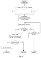
- a method for monitoring the short circuit switching device can be carried out as follows, including on Fig. 2 is referenced.
- a test pattern is generated by the controlled by the control and monitoring unit 6 inverter 2, which of the six circuit breakers located in the inverter, not closer are activated, only those four are activated, which are required for the operation of two phases.
- the one remaining phase, in Fig. 1 the "middle" phase, which is connected to both contactors 5a, 5b, remains de-energized for this test pattern.
- the current through the remaining two phases should be so dimensioned during this test pattern that no torque is generated at the motor 3.
- Fig. 4 describes the logical sequence at power up and Fig. 5 performs the shutdown.
- FIGS Fig. 6 to 9 explains which may be appropriate under certain circumstances, for example, when using a contactor with a single short-circuit bar or if the current sensors between inverter 2 and short-circuiting switching device 5 - ie elsewhere than at Fig. 1 shown - lie.
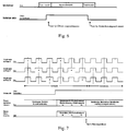
- the test pattern that must be generated by the inverter in this variant, the normal operation is much more similar than in the aforementioned embodiment and uses all six power switches in inverter 2, but with a non-operational, high frequency of rotation.
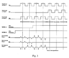
- a test pattern is generated by the inverter 2, which acts on the three phases with a very similar switching pattern, so that only small but defined voltage differences between the phases occur .
- the timing is in 6 and 7 shown, where Fig. 7 a further detail of the power-on and the test pattern used includes.
- the voltage differences between the three phases are characterized by low (in Figure 7 exaggerated) driving time differences in the high frequency (typically 10 kHz) switching operations of the circuit breakers achieved.
- the current intensity during this test pattern should be such that on average no torque is generated at the motor - this is achieved by rapid changes in the direction of the (in itself small) voltage differences.
- the currents and voltages at the three motor phases are measured by means of the current and / or voltage sensors 7, whereby the control and monitoring unit 6 redistributes the currents when closing or opening a contactor or both contactors 5a, 5b is detected.
- the Anberichtowskiunter Kunststoffe between the phases may be low, which in turn causes only small voltage differences and also very small power flows through the motor.
- a defined test pattern eg rotating voltage vector with defined direction of rotation and defined frequency - as in Fig. 7 but can also be measured at low current and voltage amplitudes and the expected change in the currents and voltages when closing or opening a contactor or both contactors are detected.
- a single (three-pole) contactor which causes the three-phase short-circuit, can be used.
- the detection can be done via the current sensors alone, a three-phase voltage measurement alone or via a combined measurement.
- the exact position of the current sensors is not decisive for this test procedure.
- a turn-on or turn-off sequence can also be introduced, which initially opens only one contactor at the beginning of each drive cycle, then activates the test pattern and then also the second one Contactor opens. After engine operation, the shutdown sequence is chosen so that ultimately both contactors have been tested for their ability to short circuit. Also, the order of driving cycle to driving cycle can be reversed.
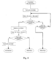
- this second embodiment of the method according to the invention can nevertheless be used to test the short circuit switching device according to FIG the in Fig. 8 and Fig. 9 illustrated flowchart are used, wherein Fig. 8 the switch-on and Fig. 9 performs the shutdown.
- the circuit-breakers located in the converter can all be deactivated (“pulse inhibit”), given a suitable speed.
- Pulse inhibit This generates no torque and no current flow, but very well the typical voltage curve for the electric motor at the three phases (“motor EMF”), wherein the amplitude and frequency of the voltage curve are speed-dependent.
- motor EMF typical voltage curve for the electric motor at the three phases
- By closing the two short-circuit contactors the voltage at the motor phases is abruptly lowered and currents occur at the motor phases, which are easily measurable. Even in this operating condition occurs - at a suitable speed - no torque (or an acceptable low braking torque) on the motor shaft.
- the effect of the short circuit switching device is thus detectable with this embodiment of the method on the change of currents or voltages.
- the last-described variant of the method according to the invention can be used in particular in those systems in which such operating points are achieved with sufficient frequency, so that the test of the short-circuit switching device 5 can be carried out with sufficient frequency in operation.
- This third embodiment can also be used in combination with the first two embodiments.
- it can be provided that, when the engine is not rotating, the switches of the converter 2 are deactivated, but test patterns are generated and supplied to the motor. The short-circuit contacts are temporarily closed and again the voltages and / or currents are measured.
- test patterns can be used not only to test the short-circuit device but also to determine the "health" of the drive, that is, to check its correct function. Also calibrations, e.g. for determining different delay times in the power electronics of the inverter are possible, wherein the control and monitoring unit 6 transmits the measurement results in a suitable form to the inverter.
Landscapes
- Engineering & Computer Science (AREA)
- Power Engineering (AREA)
- Physics & Mathematics (AREA)
- General Physics & Mathematics (AREA)
- Life Sciences & Earth Sciences (AREA)
- Sustainable Development (AREA)
- Sustainable Energy (AREA)
- Transportation (AREA)
- Mechanical Engineering (AREA)
- Control Of Ac Motors In General (AREA)
- Electric Propulsion And Braking For Vehicles (AREA)
- Inverter Devices (AREA)
Description
Die Erfindung betrifft ein Verfahren zur Überwachung der Kurzschluss-Schalteinrichtung eines Drehstrommotors für den Antrieb von Fahrzeugen, welche ausgehend von einer Gleichspannungsquelle über einen gesteuerten Umrichter gespeist wird, wobei die von einer Steuerlogik angesteuerte Kurzschluss-Schalteinrichtung mit den Eingängen des Motors verbunden ist und die Motorströme und/oder Motorspannungen gemessen werden.The invention relates to a method for monitoring the short circuit switching device of a three-phase motor for driving vehicles, which is fed from a DC voltage source via a controlled inverter, wherein the controlled by a control logic short circuit switching device is connected to the inputs of the motor and the motor currents and / or motor voltages are measured.
Elektromotoren verschiedener Bauart - insbesondere aber Permanentmagnet-erregte Synchronmotoren - benötigen ab einer bestimmten Drehzahl einen "Drei-Phasen-Kurzschluss" - also die niederohmige Verbindung der drei Motor-Phasen - um abgeschaltet zu werden, da sie sonst ein ungewünschtes, starkes Bremsmoment erzeugen würden. Dazu verwendete Kurzschluss-Schütze, ganz allgemein die Kurzschluss-Schalteinrichtung, sind also eine Sicherheitseinrichtung, die bei Auftreten einer Abschaltbedingung ausgelöst wird und damit den sicheren Zustand des Drehstrommotors durch einen "Drei-Phasen-Kurzschluss" (und somit nahezu momentenfreies Drehen) herbeiführt.Electric motors of various types - but in particular permanent magnet-excited synchronous motors - need from a certain speed a "three-phase short circuit" - ie the low-impedance connection of the three motor phases - to be switched off, otherwise they would produce an unwanted, strong braking torque , Short-circuit contactors used for this purpose, generally the short circuit switching device, are thus a safety device which is triggered when a shutdown condition occurs and thus brings about the safe state of the three-phase motor by means of a "three-phase short circuit" (and thus virtually torque-free rotation).
Der Überwachung der Kurzschluss-Schalteinrichtung kommt bei Einsatz des Elektromotors in einer sicherheits-relevanten Anwendung eine besondere Rolle zu, da die Einrichtung, die den sicheren Zustand herbeiführen kann, nämlich die Kurzschluss-Schütze, in regelmäßigen Abständen auf ihre Wirksamkeit hin überprüft werden muss. Diese Überprüfungen müssen zu geeigneten Zeitpunkten durchgeführt werden, da sie den normalen Betrieb des Elektromotors unterbrechen, und sie sollen mit vorhandenen Einrichtungen einfach und verlässlich durchgeführt werden können - idealerweise beim Einschaltvorgang. Die Sicherheitsaspekte treffen im Besonderen für den Einsatz in Elektro- und Hybridfahrzeugen zu.The monitoring of the short circuit switching device is when using the electric motor in a safety-relevant application to a special role, since the device that can bring about the safe state, namely the short-circuit contactors, must be checked at regular intervals for their effectiveness. These checks must be carried out at appropriate times, as they interrupt the normal operation of the electric motor, and they should be able to be carried out easily and reliably with existing equipment, ideally at the time of switch-on. The safety aspects apply in particular for use in electric and hybrid vehicles.
Gemäß der Druckschrift
Die Druckschrift
Es ist eine Aufgabe der Erfindung, ein Verfahren und eine zugehörige Vorrichtung zu schaffen, welche die Überwachung der Kurzschluss-Schalteinrichtung für Drehstrommotoren auf eine solche Weise erlaubt, dass der Betrieb eines angetriebenen Kraftfahrzeugs nicht merklich gestört und die Sicherheit in keiner Weise gefährdet wird.It is an object of the invention to provide a method and associated apparatus which monitor the short-circuit switching device for three-phase motors allowed in such a way that the operation of a powered motor vehicle is not significantly disturbed and safety in any way is compromised.
Diese Aufgabe wird mit einem Verfahren nach Anspruch 1 gelöst.This object is achieved by a method according to claim 1.
Dank der Erfindung können Kurzschlussschütze in Fahrzeugen regelmäßig und mit einfachen, ohnedies vorhandenen Mitteln überprüft werden, ohne dass eine für den Benutzer ersichtliche Beeinträchtigung des Fahrverhaltens, beispielsweise durch Entstehen unerwünschter Motormomente, auftritt oder Betriebspausen erforderlich wären. Die Auswertung wird im Allgemeinen eine Anzeige für den Fahrer und/oder ein Abspeichern und/oder Eingriffe in das Fahrmanagement des Fahrzeuges umfassen.Thanks to the invention, short-circuit contactors in vehicles can be checked regularly and with simple, without existing means, without any apparent for the user impairment of driving behavior, for example, by the emergence of undesirable engine torque, occurs or breaks would be required. The evaluation will generally include an indication to the driver and / or storage and / or intervention in the driving management of the vehicle.
Eine zweckmäßige Variante der Erfindung sieht vor, dass mit Hilfe des gesteuerten Umrichters während einer Testphase Testmuster erzeugt und dem Motor zugeführt werden, wobei nur jene Leistungsschalter aktiviert werden, die zum Betrieb von zwei Motor-Phasen benötigt werden, wobei eine Phase stromlos bleibt und die Stromstärke durch die übrigen beiden Phasen während des Testmusters so bemessen ist, dass der Motor nahezu kein Drehmoment erzeugt, während des Testmusters die Ströme und/oder Spannungen an den Motor-Phasen gemessen und die Umverteilung der Ströme und/oder Spannungen bei Schließen bzw. Öffnen der Kurzschlusskontakte erfasst und ausgewertet wird.An expedient variant of the invention provides that test patterns are generated and supplied to the motor with the aid of the controlled converter during a test phase, wherein only those power switches are activated which are required for the operation of two motor phases, wherein one phase remains de-energized and the Amperage is dimensioned by the remaining two phases during the test pattern so that the motor generates almost no torque, during the test pattern, the currents and / or voltages measured at the motor phases and the redistribution of currents and / or voltages at closing or opening the short-circuit contacts are detected and evaluated.
Bei einer vorteilhaften Ausführungsform kann vorgesehen sein, dass mit Hilfe des gesteuerten Umrichters während einer Testphase Testmuster erzeugt und dem Motor zugeführt werden, wobei jede der Motor-Phasen mit so geringfügig voneinander abweichenden Schaltmustern beaufschlagt wird, dass definierte, geringe Spannungsdifferenzen zwischen den Motor-Phasen auftreten und der Motor nahezu kein Drehmoment liefert und während des Testmusters die Ströme und/oder Spannungen an den Motor-Phasen gemessen und die Umverteilung der Ströme und/oder Spannungen bei Schließen bzw. Öffnen der Kurzschlusskontakte erfasst und ausgewertet wird.In an advantageous embodiment it can be provided that with the aid of the controlled converter during a test phase test patterns are generated and supplied to the motor, wherein each of the motor phases is so slightly different from each other switching patterns applied that defined, small voltage differences between the motor phases occur and the motor supplies almost no torque and measured during the test pattern, the currents and / or voltages at the motor phases and the Redistribution of currents and / or voltages when closing or opening the short-circuit contacts is detected and evaluated.
Dabei ist es empfehlenswert, wenn es bei Stillstand des Motors ausgeführt wird.It is recommended that it be executed when the engine is at a standstill.
Eine andere vorteilhafte Variante des Verfahrens sieht vor, es bei rotierendem Motor, jedoch in einem Drehzahlbereich durchgeführt wird, in dem keine passive Rekuperation über die Schaltstrecken des Umrichters überbrückende Dioden auftritt.Another advantageous variant of the method provides, it is carried out with a rotating motor, but in a speed range in which no passive recuperation occurs over the switching paths of the inverter bridging diodes.
In diesem Fall empfiehlt es sich, dass während des Betriebes jedoch zu Betriebsphasen, die kein antreibendes/bremsendes Moment seitens des Motors erfordern, die Leistungsschalter des Umrichters desaktiviert werden, die beim vorübergehenden Schließen der Kurzschlusskontakte auf Grund der an den Motorwicklungen liegenden Spannungen auftretenden Ströme gemessen werden und auf Basis der auftretenden Ströme- und oder Spannungen in den einzelnen Motor-Phasen das korrekte Öffnen/Schließen der Kurzschlusskontakte erfasst und ausgewertet wird.In this case, it is recommended that during operation, however, at operating phases that do not require a driving / braking torque from the motor, the circuit breakers of the inverter be inactivated, which measured when temporarily closing the short-circuit contacts due to the currents occurring at the motor windings voltages and the correct opening / closing of the short-circuit contacts is detected and evaluated on the basis of the occurring currents and / or voltages in the individual motor phases.
Bei einer weiteren zweckmäßigen Variante kann vorgesehen sein, dass bei rotierendem, unbelasteten Motor Testmuster erzeugt und dem Motor zugeführt werden und die beim vorübergehenden Schließen der Kurzschlusskontakte auftretenden Ströme und/oder Spannungen gemessen werden sowie auf Basis dieser Messungen das korrekte Öffnen/Schließen der Kurzschlusskontakte erfasst und ausgewertet wird.In a further expedient variant, it can be provided that test patterns are generated and supplied to the motor when the motor is rotating and the currents and / or voltages occurring during temporary closing of the short-circuit contacts are measured, and the correct opening / closing of the short-circuit contacts is detected on the basis of these measurements and evaluated.
Besonders vorteilhaft ist eine Vorrichtung zur Durchführung des Verfahrens zur Überwachung der Kurzschluss-Schalteinrichtung eines Drehstrommotors für den Antrieb von Fahrzeugen, welche ausgehend von einer Gleichspannungsquelle über einen gesteuerten Umrichter gespeist wird, wobei die von einer Steuer- und Überwachungseinheit angesteuerte Kurzschluss-Schalteinrichtung mit den Eingängen des Motors verbunden ist und Strom- und/ oder Spannungssensoren zur Messung der Motorströme und/ oder Spannungen vorgesehen sind, welche entsprechende Signale an die Steuer- und Überwachungseinheit liefern, die dazu eingerichtet ist, einerseits Ansteuersignale an die Kurzschluss-Schalteinrichtung und andererseits Steuersignale an den Umrichter zu liefern, sowie auf Basis der Strom- und/oder Spannungsverteilung in den einzelnen Motor-Phasen das korrekte Öffnen/Schließen der Kurzschlusskontakte zu erfassen und auszuwerten.Particularly advantageous is a device for carrying out the method for monitoring the short circuit switching device of a three-phase motor for driving vehicles, which is fed from a DC voltage source via a controlled inverter, wherein the controlled by a control and monitoring unit short-circuit switching device with the inputs is connected to the motor and current and / or voltage sensors for measuring the motor currents and / or voltages are provided, which supply corresponding signals to the control and monitoring unit, which is adapted, on the one hand control signals to the short circuit switching device and on the other hand control signals to the To supply inverter, and based on the current and / or voltage distribution in the individual motor phases to detect the correct opening / closing of the short-circuit contacts and evaluate.
Die Erfindung samt weiteren Vorteilen ist im Folgenden an Hand beispielsweiser Ausführungsformen näher erläutert, die in der Zeichnung veranschaulicht sind. In dieser zeigen:
-
Fig. 1 ein Blockschaltbild eines elektrischen Antriebsstranges in einem Kraftfahrzeug, -
Fig. 2 den zeitlichen Ablauf einer ersten Ausführungsform des erfindungsgemäßen Verfahrens, -
Fig. 3 den zeitlichen Ablauf einer ersten Ausführungsform des erfindungsgemäßen Verfahrens in einer Detaildarstellung der Einschaltsituation, -
Fig. 4 ein Ablaufdiagramm betreffend das erfindungsgemäße Verfahren in seiner ersten Ausführungsform in einer Einschaltsituation, -
Fig. 5 ein weiteres Ablaufdiagramm betreffend das erfindungsgemäße Verfahren in seiner ersten Ausführungsform in einer Ausschaltsituation, -
Fig. 6 den zeitlichen Ablauf einer zweiten Ausführungsform des erfindungsgemäßen Verfahrens, -
Fig. 7 den zeitlichen Ablauf einer zweiten Ausführungsform des erfindungsgemäßen Verfahrens in einer Detaildarstellung der Einschaltsituation, -
Fig. 8 ein Ablaufdiagramm betreffend das erfindungsgemäße Verfahren in seiner zweiten Ausführungsform in einer Einschaltsituation, -
Fig. 9 ein weiteres Ablaufdiagramm betreffend das erfindungsgemäße Verfahren in seiner zweiten Ausführungsform in einer Ausschaltsituation, -
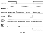
Fig. 10 den zeitlichen Ablauf einer dritten Ausführungsform des erfindungsgemäßen Verfahrens,
-
Fig. 1 a block diagram of an electric drive train in a motor vehicle, -
Fig. 2 the timing of a first embodiment of the method according to the invention, -
Fig. 3 the timing of a first embodiment of the method according to the invention in a detailed representation of the switch-on situation, -
Fig. 4 a flowchart relating to the inventive method in its first embodiment in a switch-on situation, -
Fig. 5 a further flowchart relating to the method according to the invention in its first embodiment in a switch-off situation, -
Fig. 6 the time sequence of a second embodiment of the method according to the invention, -
Fig. 7 the timing of a second embodiment of the method according to the invention in a detailed representation of the switch-on situation, -
Fig. 8 a flowchart relating to the inventive method in its second embodiment in a switch-on situation, -
Fig. 9 a further flowchart relating to the method according to the invention in its second embodiment in a switch-off situation, -
Fig. 10 the timing of a third embodiment of the method according to the invention,
Es wird zunächst auf
Mit den Stromzuführleitungen (Phasen U, V, W) des Motors 3 ist eine Kurzschluss-Schalteinrichtung 5 verbunden, welche zwei Schütze 5a, 5b aufweist und die von einer Steuer- und Überwachungseinheit 6 angesteuert wird. Strom- und/ oder Spannungssensoren 7 liefern entsprechende Signale an die Steuerlogik 6, welche ihrerseits Ansteuersignale sa, sb an die beiden Schütze liefern kann und andererseits Steuersignale su an den Umrichter 2. Hier ist die gesamte Steuerung in einem Block zusammengefasst, doch ist es klar, dass der Umrichter auch eine eigene Ansteuereinheit enthalten kann, zu welcher dann eine Steuer- und Überwachungseinheit der Schalteinrichtung 5 Signale senden kann.To the power supply lines (phases U, V, W) of the
Ob man sämtliche Ströme und Spannungen des Drehstromsystems an den drei Motor-Phasen des Motors 3 misst, ist von Fall zu Fall verschieden, wobei oft mit zwei Stromsensoren das Auslangen gefunden werden kann, da sich in einem Drehstromsystem aus der Messung der Ströme in zwei Leitern der Strom in dem dritten Leiter ergibt.Whether one measures all the currents and voltages of the three-phase system at the three motor phases of the
Die Kontakte der beiden Schütze 5a, 5b sind bei eingeschaltetem Steuerstrom offen, was einen normalen Motor- bzw. Generatorbetrieb erlaubt. Bei Wegfall des Steuerstroms schließen die Kontakte in jedem Schütz je zwei Phasen des Elektromotors kurz. Es sind jedoch auch andere elektromechanische Ausführungen als die Anordnung von zwei Schützen möglich. So könnte beispielsweise - bei einer noch weiter unten beschriebenen Variante der Erfindung - ein einziger angetriebener Kontaktsteg für den Kurzschluss aller drei Phasen des Elektromotors vorgesehen sein.The contacts of the two
Da ein direkter Kurzschluss zwischen zwei oder drei Motor-Phasen im normalen Betrieb des seitens des Umrichters 2 mit Strom gespeisten Motors 3 nicht zulässig ist und auch die im Motor 3 befindlichen Wicklungen neben einer Induktivität auch eine niederohmige Verbindung zwischen den Motor-Phasen bilden, ist eine Messung zur Erkennung ob die Kurzschluss-Schalteinrichtung 5 offen oder geschlossen ist nicht ohne Weiteres möglich. Daher wurden im Rahmen der Erfindung ein Verfahren bzw. dessen Varianten geschaffen, was nachstehend erläutert wird.Since a direct short circuit between two or three motor phases during normal operation of the
Mit der beschriebenen Vorrichtung kann ein Verfahren zur Überwachung der Kurzschluss-Schalteinrichtung wie folgt durchgeführt werden, wozu auch auf
Das zuvor beschriebene Verfahren ist auch in den Ablaufdiagrammen der
Nun wird eine zweite Ausführungsform der Erfindung unter Bezugnahme auf die
Zu vereinbarten Betriebszeitpunkten (z.B. unmittelbar nach dem Einschalten) oder nach Anforderung durch die Steuer- und Überwachungseinheit 6 wird ein Testmuster durch den Umrichter 2 erzeugt, welches die drei Phasen mit einem sehr ähnlichen Schaltmuster beaufschlagt, sodass nur geringe aber definierte Spannungsdifferenzen zwischen den Phasen auftreten. Der zeitliche Ablauf ist in
Schließlich sei eine dritte Ausführungsform des erfindungsgemäßen Verfahrens unter Bezugnahme auf die
In jenen Betriebspunkten, in denen kein antreibendes Moment vom Elektromotor angefordert wird (z.B. "coasting"), können - bei geeigneter Drehzahl - die im Umrichter liegenden Leistungsschalter alle deaktiviert werden ("Impulssperre"). Dies erzeugt kein Moment und keinen Stromfluss, sehr wohl aber den für den Elektromotor typischen Spannungsverlauf an den drei Phasen ("Motor EMK"), wobei Amplitude und Frequenz des Spannungsverlaufs drehzahlabhängig sind. Durch Schließen der beiden Kurzschluss-Schütze wird die Spannung an den Motor-Phasen schlagartig gesenkt und es treten Ströme an den Motor-Phasen auf, die gut messbar sind. Auch in diesem Betriebszustand tritt - bei geeigneter Drehzahl - kein Moment (bzw. ein akzeptierbares geringes Bremsmoment) an der Motorwelle auf. Die Wirkung der Kurzschluss-Schalteinrichtung ist also auch mit dieser Ausführung des Verfahrens über die Änderung der Ströme bzw. der Spannungen nachweisbar. Das zuletzt beschriebene Variante des erfindungsgemäßen Verfahrens ist insbesondere in jenen Systemen einsetzbar, in denen derartige Betriebspunkte mit ausreichender Häufigkeit erreicht werden, sodass die Prüfung der Kurzschluss-Schalteinrichtung 5 mit ausreichender Häufigkeit im Betreib durchgeführt werden kann. Diese dritte Ausführungsform kann auch in Kombination mit den ersten beiden Ausführungsformen eingesetzt werden. Insbesondere kann man bei einer vierten Variante vorsehen, dass bei rotierendem, unbelasteten Motor nicht die Schalter des Umrichters 2 desaktiviert werden, sondern man Testmuster erzeugt und führt sie dem Motor zu. Dabei werden die Kurzschlusskontakte vorübergehend geschlossen und wiederum die Spannungen und/oder Ströme gemessen. Auf Basis der auftretenden Ströme und/oder Spannungen in den einzelnen Phasen der Drehstromleitungen wird dann das korrekte Öffnen/Schließen der Kurzschlusskontakte erfasst und ausgegeben. Dieses Verfahren kann in geeigneten Drehzahlbereichen, die meist von dem jeweiligen Motor abhängen, durchgeführt werden.In those operating points in which no driving torque is requested by the electric motor (eg "coasting"), the circuit-breakers located in the converter can all be deactivated ("pulse inhibit"), given a suitable speed. This generates no torque and no current flow, but very well the typical voltage curve for the electric motor at the three phases ("motor EMF"), wherein the amplitude and frequency of the voltage curve are speed-dependent. By closing the two short-circuit contactors, the voltage at the motor phases is abruptly lowered and currents occur at the motor phases, which are easily measurable. Even in this operating condition occurs - at a suitable speed - no torque (or an acceptable low braking torque) on the motor shaft. The effect of the short circuit switching device is thus detectable with this embodiment of the method on the change of currents or voltages. The last-described variant of the method according to the invention can be used in particular in those systems in which such operating points are achieved with sufficient frequency, so that the test of the short-
Es soll nicht unerwähnt gelassen werden, dass die Testmuster nicht nur zur Prüfung der Kurzschlusseinrichtung sondern auch zur Feststellung der "Gesundheit" des Umrichters eingesetzt werden können, also zur Prüfung dessen korrekter Funktion. Auch Kalibriervorgänge, z.B. zur Ermittlung von unterschiedlichen Verzögerungszeiten in der Leistungselektronik des Umrichters, sind möglich, wobei die Steuer- und Überwachungseinheit 6 die Messergebnisse in geeigneter Form an den Umrichter überträgt.It should not be left unmentioned that the test patterns can be used not only to test the short-circuit device but also to determine the "health" of the drive, that is, to check its correct function. Also calibrations, e.g. for determining different delay times in the power electronics of the inverter are possible, wherein the control and
Claims (6)
- A method for monitoring the short-circuiting switching device of a three-phase motor (3) for driving vehicles, which is fed from a DC voltage source (1) via a controlled converter (2), wherein the short-circuiting switching device (5) actuated by a control logic (6) is connected to the inputs of the motor, and the motor currents and/or motor voltages are measured,
characterised in that
a predetermined test pattern, which is different from the voltage/current profiles during operation, is generated with the aid of the controlled converter (2) during a test phase and is supplied to the motor (3),
the short-circuiting switching device is actuated for the activation thereof, the current and/or voltage profile is detected during the test phase by opening and closing short-circuiting contacts and,
on the basis of the current and/or voltage distribution in the individual motor phases, the correct opening/closing of the short-circuiting contacts is detected and evaluated,
wherein switching patterns are applied to each of the motor phases and deviate so slightly from one another that defined, small voltage differences occur between the motor phases and the motor delivers practically no torque, and during the test pattern the currents and/or voltages across the motor phases are measured and the redistribution of the currents and/or voltages when the short-circuiting contacts are closed and opened is detected and evaluated. - The method according to Claim 1, characterised in that said method is performed during stoppage of the motor (3).
- The method according to Claim 1, characterised in that the method is performed as the motor (3) rotates, but in a rotational speed range in which there is no passive regenerative braking via diodes bridging the clearances between open contacts of the converter.
- The method according to Claim 3, characterised in that, during operation but during operating phases that require no driving/braking torque on the part of the motor, the circuit breakers of the converter are deactivated, the currents occurring with momentary closure of the short-circuiting contacts due to the voltages applied across the motor windings are measured, and the correct opening/closing of the short-circuiting contacts is detected and output on the basis of the occurring currents and/or voltages in the individual motor phases.
- The method according to one of Claims 3 or 4, characterised in that test patterns can be produced with a rotating, unloaded motor and can be supplied to the motor, and the currents and/or voltages occurring during the momentary closure of the short-circuiting contacts can be measured, and the correct opening/closing of the short-circuiting contacts can be detected and output on the basis of these measurements.
- An apparatus for carrying out the method according to one of Claims 1 to 5 for monitoring the short-circuiting switching device (5) of a three-phase motor (3) for driving vehicles, which is fed from a DC voltage source (1) via a controlled converter (2), wherein the short-circuiting device actuated by a control and monitoring unit (6) is connected to the inputs of the motor and current and/or voltage sensors (7) for measuring the motor currents and/or voltages are provided, which deliver corresponding signals to the control and monitoring unit (6), which is configured on the one hand to deliver actuation signals (sa, sb) to the short-circuiting switching device (5) and on the other hand to deliver control signals (su) to the converter (2) and also to detect and to output the correct opening/closing of the short-circuiting contacts on the basis of the current and/or voltage distribution in the individual motor phases, wherein a predetermined test pattern, which is different from the voltage/current profiles during operation, is generated with the aid of the controlled converter (2) during a test phase and is supplied to the motor (3), wherein switching patterns are applied to each of the motor phases and deviate so slightly from one another that defined, small voltage differences occur between the motor phases and the motor delivers practically no torque, and during the test pattern the currents and/or voltages across the motor phases are measured and the redistribution of the currents and/or voltages when the short-circuiting contacts are closed and opened is detected and evaluated.
Applications Claiming Priority (2)
| Application Number | Priority Date | Filing Date | Title |
|---|---|---|---|
| ATA50023/2012A AT512477B1 (en) | 2012-02-03 | 2012-02-03 | METHOD AND DEVICE FOR MONITORING THE SHORT-CIRCUIT SWITCHING DEVICE OF A THREE-PHASE MOTOR |
| PCT/AT2013/050027 WO2013113051A2 (en) | 2012-02-03 | 2013-01-30 | Method and apparatus for monitoring the short-circuiting switching device of a three-phase motor |
Publications (2)
| Publication Number | Publication Date |
|---|---|
| EP2810366A2 EP2810366A2 (en) | 2014-12-10 |
| EP2810366B1 true EP2810366B1 (en) | 2016-03-30 |
Family
ID=48047761
Family Applications (1)
| Application Number | Title | Priority Date | Filing Date |
|---|---|---|---|
| EP13714180.0A Active EP2810366B1 (en) | 2012-02-03 | 2013-01-30 | Method and apparatus for monitoring the short-circuiting switching device of a three-phase motor |
Country Status (4)
| Country | Link |
|---|---|
| US (1) | US9329242B2 (en) |
| EP (1) | EP2810366B1 (en) |
| AT (1) | AT512477B1 (en) |
| WO (1) | WO2013113051A2 (en) |
Cited By (1)
| Publication number | Priority date | Publication date | Assignee | Title |
|---|---|---|---|---|
| CN107607866A (en) * | 2017-11-09 | 2018-01-19 | 黄茂连 | A kind of switch testing method based on switch testing equipment |
Families Citing this family (9)
| Publication number | Priority date | Publication date | Assignee | Title |
|---|---|---|---|---|
| DE102014202198A1 (en) * | 2014-02-06 | 2015-08-06 | Robert Bosch Gmbh | Method for checking an automatic parking brake system |
| CN106950497B (en) * | 2017-04-01 | 2023-09-08 | 中国第一汽车股份有限公司 | Strong electricity management and test device for new energy automobile motor test |
| US11128244B2 (en) * | 2017-10-25 | 2021-09-21 | Mitsuba Corporation | Device for detecting rotation direction and method for detecting rotation direction of motor, and motor control device |
| CN109406997B (en) * | 2018-11-30 | 2020-11-10 | 北京新能源汽车股份有限公司 | Method and device for testing active short-circuit relay of motor and storage medium |
| EP3811481B1 (en) * | 2018-12-21 | 2023-05-17 | Siemens Gamesa Renewable Energy A/S | Method for determination of a location of a short circuit fault in a generator arrangement, generator arrangement, wind turbine, computer program and electronically readable medium |
| DE102019204303A1 (en) * | 2019-03-28 | 2020-10-01 | Siemens Aktiengesellschaft | Switching device, high-voltage circuit breaker and method for operating the switching device |
| CN112858850B (en) * | 2021-01-08 | 2024-06-07 | 胜达克半导体科技(上海)股份有限公司 | High-voltage module testing method for three-phase direct-current motor driving chip |
| US11929698B2 (en) * | 2021-03-23 | 2024-03-12 | Snap-On Incorporated | Short circuit protection for a BLDC motor |
| DE102023107166A1 (en) | 2023-03-22 | 2024-09-26 | Bayerische Motoren Werke Aktiengesellschaft | Short-circuit device for an electric drive machine |
Family Cites Families (7)
| Publication number | Priority date | Publication date | Assignee | Title |
|---|---|---|---|---|
| US5617281A (en) * | 1994-06-01 | 1997-04-01 | Eaton Corporation | Low cost circuit controller |
| DE19837796A1 (en) * | 1998-08-20 | 2000-02-24 | Wilo Gmbh | Procedure for determining the pump condition |
| JP4526612B2 (en) * | 1999-02-25 | 2010-08-18 | 三菱電機株式会社 | Servo device |
| US20030193308A1 (en) * | 2002-04-16 | 2003-10-16 | Richardson Gordon D. | Apparatus and method for testing a motor-shorting relay |
| EP1487096A1 (en) * | 2003-06-12 | 2004-12-15 | Hauni Maschinenbau AG | Servo-Drive for a moving part |
| JP4438833B2 (en) * | 2007-07-04 | 2010-03-24 | トヨタ自動車株式会社 | Abnormality detection apparatus and abnormality detection method for power converter |
| JP4361116B2 (en) * | 2008-01-09 | 2009-11-11 | ファナック株式会社 | Motor drive device with dynamic brake circuit failure detection function |
-
2012
- 2012-02-03 AT ATA50023/2012A patent/AT512477B1/en active
-
2013
- 2013-01-30 WO PCT/AT2013/050027 patent/WO2013113051A2/en active Application Filing
- 2013-01-30 EP EP13714180.0A patent/EP2810366B1/en active Active
- 2013-01-30 US US14/374,850 patent/US9329242B2/en active Active
Cited By (1)
| Publication number | Priority date | Publication date | Assignee | Title |
|---|---|---|---|---|
| CN107607866A (en) * | 2017-11-09 | 2018-01-19 | 黄茂连 | A kind of switch testing method based on switch testing equipment |
Also Published As
| Publication number | Publication date |
|---|---|
| AT512477B1 (en) | 2016-09-15 |
| US9329242B2 (en) | 2016-05-03 |
| AT512477A1 (en) | 2013-08-15 |
| US20150002187A1 (en) | 2015-01-01 |
| WO2013113051A3 (en) | 2014-02-20 |
| EP2810366A2 (en) | 2014-12-10 |
| WO2013113051A2 (en) | 2013-08-08 |
Similar Documents
| Publication | Publication Date | Title |
|---|---|---|
| EP2810366B1 (en) | Method and apparatus for monitoring the short-circuiting switching device of a three-phase motor | |
| DE102007059492B4 (en) | industrial robots | |
| EP3469705B1 (en) | Method and protective device for limiting the torque for an electrical machine | |
| DE102007036027B4 (en) | Fault handling of inverter-driven PM motor drives | |
| EP1655829B1 (en) | Circuit arrangement and method for control of an electric motor, in particular of a washing machine | |
| EP2499737B1 (en) | Method for checking the plausibility of the torque of an electrical machine and machine controller for controlling an electrical machine and for carrying out the method | |
| EP2715932B1 (en) | Method and device for operating a brushless motor | |
| DE102012206570B4 (en) | A power supply control apparatus for a vehicle having an energy supply interruption unit and an electric insulation deterioration detector | |
| WO2017186436A1 (en) | System for actively short-circuiting phases of an inverter and motor vehicle drive | |
| DE102012101508A1 (en) | Method for operating e.g. permanently excited synchronous machine for motor car, involves comparing voltage in intermediate circuit with minimum limit voltage value in circuit, to open converter valves so as to drive machine | |
| DE102014112101A1 (en) | CONTROL UNIT FOR ELECTRIC MOTOR | |
| EP3058652B1 (en) | Control unit with safety shutdown | |
| EP3449557A1 (en) | Inverter arrangement, electric drive system, and method for discharging a dc link capacitor in an inverter arrangement | |
| DE112015003140T5 (en) | Power conversion device | |
| EP2550734B1 (en) | Method for operating a brushless electric motor | |
| EP2939341A2 (en) | Method and device for operating a brushless dc motor | |
| EP3914501B1 (en) | Method for disconnecting a multi-phase electric motor of an electromechanical motor vehicle power steering system from a direct voltage source, and control unit for controlling the electric motor | |
| DE102019217836A1 (en) | Method for controlling the operation of an electric vehicle drive unit with two controllers | |
| WO2016046247A1 (en) | Method and device for monitoring an electrical network in a rail vehicle, and rail vehicle | |
| WO2011047952A1 (en) | Monitoring device for an electrical high voltage network of a vehicle | |
| AT522121B1 (en) | Method for operating a drive device, drive device and motor vehicle | |
| EP2654155B1 (en) | Power converter, and method for operating a power converter | |
| EP3314744B1 (en) | Method and device for checking a drive current of an electric machine | |
| DE102015003446A1 (en) | Supply of a motor vehicle with voltage test | |
| DE102015012540A1 (en) | Method for operating a steering system |
Legal Events
| Date | Code | Title | Description |
|---|---|---|---|
| PUAI | Public reference made under article 153(3) epc to a published international application that has entered the european phase |
Free format text: ORIGINAL CODE: 0009012 |
|
| 17P | Request for examination filed |
Effective date: 20140731 |
|
| AK | Designated contracting states |
Kind code of ref document: A2 Designated state(s): AL AT BE BG CH CY CZ DE DK EE ES FI FR GB GR HR HU IE IS IT LI LT LU LV MC MK MT NL NO PL PT RO RS SE SI SK SM TR |
|
| AX | Request for extension of the european patent |
Extension state: BA ME |
|
| DAX | Request for extension of the european patent (deleted) | ||
| REG | Reference to a national code |
Ref country code: DE Ref legal event code: R079 Ref document number: 502013002370 Country of ref document: DE Free format text: PREVIOUS MAIN CLASS: H02P0003120000 Ipc: G01R0031327000 |
|
| GRAP | Despatch of communication of intention to grant a patent |
Free format text: ORIGINAL CODE: EPIDOSNIGR1 |
|
| RIC1 | Information provided on ipc code assigned before grant |
Ipc: H02P 3/22 20060101ALI20150827BHEP Ipc: G01R 31/40 20140101ALI20150827BHEP Ipc: B60L 3/00 20060101ALI20150827BHEP Ipc: G01R 31/34 20060101ALI20150827BHEP Ipc: H02P 29/02 20060101ALI20150827BHEP Ipc: G01R 31/327 20060101AFI20150827BHEP |
|
| INTG | Intention to grant announced |
Effective date: 20150925 |
|
| GRAS | Grant fee paid |
Free format text: ORIGINAL CODE: EPIDOSNIGR3 |
|
| GRAA | (expected) grant |
Free format text: ORIGINAL CODE: 0009210 |
|
| AK | Designated contracting states |
Kind code of ref document: B1 Designated state(s): AL AT BE BG CH CY CZ DE DK EE ES FI FR GB GR HR HU IE IS IT LI LT LU LV MC MK MT NL NO PL PT RO RS SE SI SK SM TR |
|
| REG | Reference to a national code |
Ref country code: GB Ref legal event code: FG4D Free format text: NOT ENGLISH |
|
| REG | Reference to a national code |
Ref country code: CH Ref legal event code: EP |
|
| REG | Reference to a national code |
Ref country code: AT Ref legal event code: REF Ref document number: 785950 Country of ref document: AT Kind code of ref document: T Effective date: 20160415 |
|
| REG | Reference to a national code |
Ref country code: IE Ref legal event code: FG4D Free format text: LANGUAGE OF EP DOCUMENT: GERMAN |
|
| REG | Reference to a national code |
Ref country code: DE Ref legal event code: R096 Ref document number: 502013002370 Country of ref document: DE |
|
| REG | Reference to a national code |
Ref country code: LT Ref legal event code: MG4D |
|
| PG25 | Lapsed in a contracting state [announced via postgrant information from national office to epo] |
Ref country code: FI Free format text: LAPSE BECAUSE OF FAILURE TO SUBMIT A TRANSLATION OF THE DESCRIPTION OR TO PAY THE FEE WITHIN THE PRESCRIBED TIME-LIMIT Effective date: 20160330 Ref country code: NO Free format text: LAPSE BECAUSE OF FAILURE TO SUBMIT A TRANSLATION OF THE DESCRIPTION OR TO PAY THE FEE WITHIN THE PRESCRIBED TIME-LIMIT Effective date: 20160630 Ref country code: GR Free format text: LAPSE BECAUSE OF FAILURE TO SUBMIT A TRANSLATION OF THE DESCRIPTION OR TO PAY THE FEE WITHIN THE PRESCRIBED TIME-LIMIT Effective date: 20160701 Ref country code: HR Free format text: LAPSE BECAUSE OF FAILURE TO SUBMIT A TRANSLATION OF THE DESCRIPTION OR TO PAY THE FEE WITHIN THE PRESCRIBED TIME-LIMIT Effective date: 20160330 |
|
| REG | Reference to a national code |
Ref country code: NL Ref legal event code: MP Effective date: 20160330 |
|
| PG25 | Lapsed in a contracting state [announced via postgrant information from national office to epo] |
Ref country code: RS Free format text: LAPSE BECAUSE OF FAILURE TO SUBMIT A TRANSLATION OF THE DESCRIPTION OR TO PAY THE FEE WITHIN THE PRESCRIBED TIME-LIMIT Effective date: 20160330 Ref country code: SE Free format text: LAPSE BECAUSE OF FAILURE TO SUBMIT A TRANSLATION OF THE DESCRIPTION OR TO PAY THE FEE WITHIN THE PRESCRIBED TIME-LIMIT Effective date: 20160330 Ref country code: LV Free format text: LAPSE BECAUSE OF FAILURE TO SUBMIT A TRANSLATION OF THE DESCRIPTION OR TO PAY THE FEE WITHIN THE PRESCRIBED TIME-LIMIT Effective date: 20160330 Ref country code: LT Free format text: LAPSE BECAUSE OF FAILURE TO SUBMIT A TRANSLATION OF THE DESCRIPTION OR TO PAY THE FEE WITHIN THE PRESCRIBED TIME-LIMIT Effective date: 20160330 |
|
| PG25 | Lapsed in a contracting state [announced via postgrant information from national office to epo] |
Ref country code: NL Free format text: LAPSE BECAUSE OF FAILURE TO SUBMIT A TRANSLATION OF THE DESCRIPTION OR TO PAY THE FEE WITHIN THE PRESCRIBED TIME-LIMIT Effective date: 20160330 |
|
| PG25 | Lapsed in a contracting state [announced via postgrant information from national office to epo] |
Ref country code: PL Free format text: LAPSE BECAUSE OF FAILURE TO SUBMIT A TRANSLATION OF THE DESCRIPTION OR TO PAY THE FEE WITHIN THE PRESCRIBED TIME-LIMIT Effective date: 20160330 Ref country code: EE Free format text: LAPSE BECAUSE OF FAILURE TO SUBMIT A TRANSLATION OF THE DESCRIPTION OR TO PAY THE FEE WITHIN THE PRESCRIBED TIME-LIMIT Effective date: 20160330 Ref country code: IS Free format text: LAPSE BECAUSE OF FAILURE TO SUBMIT A TRANSLATION OF THE DESCRIPTION OR TO PAY THE FEE WITHIN THE PRESCRIBED TIME-LIMIT Effective date: 20160730 |
|
| PG25 | Lapsed in a contracting state [announced via postgrant information from national office to epo] |
Ref country code: ES Free format text: LAPSE BECAUSE OF FAILURE TO SUBMIT A TRANSLATION OF THE DESCRIPTION OR TO PAY THE FEE WITHIN THE PRESCRIBED TIME-LIMIT Effective date: 20160330 Ref country code: PT Free format text: LAPSE BECAUSE OF FAILURE TO SUBMIT A TRANSLATION OF THE DESCRIPTION OR TO PAY THE FEE WITHIN THE PRESCRIBED TIME-LIMIT Effective date: 20160801 Ref country code: SK Free format text: LAPSE BECAUSE OF FAILURE TO SUBMIT A TRANSLATION OF THE DESCRIPTION OR TO PAY THE FEE WITHIN THE PRESCRIBED TIME-LIMIT Effective date: 20160330 Ref country code: SM Free format text: LAPSE BECAUSE OF FAILURE TO SUBMIT A TRANSLATION OF THE DESCRIPTION OR TO PAY THE FEE WITHIN THE PRESCRIBED TIME-LIMIT Effective date: 20160330 Ref country code: RO Free format text: LAPSE BECAUSE OF FAILURE TO SUBMIT A TRANSLATION OF THE DESCRIPTION OR TO PAY THE FEE WITHIN THE PRESCRIBED TIME-LIMIT Effective date: 20160330 Ref country code: CZ Free format text: LAPSE BECAUSE OF FAILURE TO SUBMIT A TRANSLATION OF THE DESCRIPTION OR TO PAY THE FEE WITHIN THE PRESCRIBED TIME-LIMIT Effective date: 20160330 |
|
| REG | Reference to a national code |
Ref country code: FR Ref legal event code: PLFP Year of fee payment: 5 |
|
| PG25 | Lapsed in a contracting state [announced via postgrant information from national office to epo] |
Ref country code: IT Free format text: LAPSE BECAUSE OF FAILURE TO SUBMIT A TRANSLATION OF THE DESCRIPTION OR TO PAY THE FEE WITHIN THE PRESCRIBED TIME-LIMIT Effective date: 20160330 |
|
| REG | Reference to a national code |
Ref country code: DE Ref legal event code: R097 Ref document number: 502013002370 Country of ref document: DE |
|
| PG25 | Lapsed in a contracting state [announced via postgrant information from national office to epo] |
Ref country code: DK Free format text: LAPSE BECAUSE OF FAILURE TO SUBMIT A TRANSLATION OF THE DESCRIPTION OR TO PAY THE FEE WITHIN THE PRESCRIBED TIME-LIMIT Effective date: 20160330 |
|
| PLBE | No opposition filed within time limit |
Free format text: ORIGINAL CODE: 0009261 |
|
| STAA | Information on the status of an ep patent application or granted ep patent |
Free format text: STATUS: NO OPPOSITION FILED WITHIN TIME LIMIT |
|
| 26N | No opposition filed |
Effective date: 20170103 |
|
| PG25 | Lapsed in a contracting state [announced via postgrant information from national office to epo] |
Ref country code: SI Free format text: LAPSE BECAUSE OF FAILURE TO SUBMIT A TRANSLATION OF THE DESCRIPTION OR TO PAY THE FEE WITHIN THE PRESCRIBED TIME-LIMIT Effective date: 20160330 Ref country code: BE Free format text: LAPSE BECAUSE OF NON-PAYMENT OF DUE FEES Effective date: 20170131 |
|
| REG | Reference to a national code |
Ref country code: CH Ref legal event code: PL |
|
| GBPC | Gb: european patent ceased through non-payment of renewal fee |
Effective date: 20170130 |
|
| PG25 | Lapsed in a contracting state [announced via postgrant information from national office to epo] |
Ref country code: MC Free format text: LAPSE BECAUSE OF FAILURE TO SUBMIT A TRANSLATION OF THE DESCRIPTION OR TO PAY THE FEE WITHIN THE PRESCRIBED TIME-LIMIT Effective date: 20160330 |
|
| PG25 | Lapsed in a contracting state [announced via postgrant information from national office to epo] |
Ref country code: LI Free format text: LAPSE BECAUSE OF NON-PAYMENT OF DUE FEES Effective date: 20170131 Ref country code: CH Free format text: LAPSE BECAUSE OF NON-PAYMENT OF DUE FEES Effective date: 20170131 |
|
| REG | Reference to a national code |
Ref country code: IE Ref legal event code: MM4A |
|
| PG25 | Lapsed in a contracting state [announced via postgrant information from national office to epo] |
Ref country code: GB Free format text: LAPSE BECAUSE OF NON-PAYMENT OF DUE FEES Effective date: 20170130 Ref country code: LU Free format text: LAPSE BECAUSE OF NON-PAYMENT OF DUE FEES Effective date: 20170130 |
|
| REG | Reference to a national code |
Ref country code: FR Ref legal event code: PLFP Year of fee payment: 6 |
|
| REG | Reference to a national code |
Ref country code: BE Ref legal event code: MM Effective date: 20170131 |
|
| PG25 | Lapsed in a contracting state [announced via postgrant information from national office to epo] |
Ref country code: IE Free format text: LAPSE BECAUSE OF NON-PAYMENT OF DUE FEES Effective date: 20170130 |
|
| PG25 | Lapsed in a contracting state [announced via postgrant information from national office to epo] |
Ref country code: MT Free format text: LAPSE BECAUSE OF FAILURE TO SUBMIT A TRANSLATION OF THE DESCRIPTION OR TO PAY THE FEE WITHIN THE PRESCRIBED TIME-LIMIT Effective date: 20160330 |
|
| PG25 | Lapsed in a contracting state [announced via postgrant information from national office to epo] |
Ref country code: AL Free format text: LAPSE BECAUSE OF FAILURE TO SUBMIT A TRANSLATION OF THE DESCRIPTION OR TO PAY THE FEE WITHIN THE PRESCRIBED TIME-LIMIT Effective date: 20160330 |
|
| REG | Reference to a national code |
Ref country code: DE Ref legal event code: R081 Ref document number: 502013002370 Country of ref document: DE Owner name: TTTECH AUTO AG, AT Free format text: FORMER OWNER: FTS COMPUTERTECHNIK GMBH, WIEN, AT Ref country code: DE Ref legal event code: R082 Ref document number: 502013002370 Country of ref document: DE Representative=s name: VIERING, JENTSCHURA & PARTNER MBB PATENT- UND , DE Ref country code: DE Ref legal event code: R081 Ref document number: 502013002370 Country of ref document: DE Owner name: TTTECH COMPUTERTECHNIK AG, AT Free format text: FORMER OWNER: FTS COMPUTERTECHNIK GMBH, WIEN, AT |
|
| REG | Reference to a national code |
Ref country code: AT Ref legal event code: MM01 Ref document number: 785950 Country of ref document: AT Kind code of ref document: T Effective date: 20180130 |
|
| PG25 | Lapsed in a contracting state [announced via postgrant information from national office to epo] |
Ref country code: AT Free format text: LAPSE BECAUSE OF NON-PAYMENT OF DUE FEES Effective date: 20180130 |
|
| REG | Reference to a national code |
Ref country code: DE Ref legal event code: R082 Ref document number: 502013002370 Country of ref document: DE Representative=s name: VIERING, JENTSCHURA & PARTNER MBB PATENT- UND , DE Ref country code: DE Ref legal event code: R081 Ref document number: 502013002370 Country of ref document: DE Owner name: TTTECH AUTO AG, AT Free format text: FORMER OWNER: TTTECH COMPUTERTECHNIK AG, WIEN, AT |
|
| PG25 | Lapsed in a contracting state [announced via postgrant information from national office to epo] |
Ref country code: HU Free format text: LAPSE BECAUSE OF FAILURE TO SUBMIT A TRANSLATION OF THE DESCRIPTION OR TO PAY THE FEE WITHIN THE PRESCRIBED TIME-LIMIT; INVALID AB INITIO Effective date: 20130130 |
|
| PG25 | Lapsed in a contracting state [announced via postgrant information from national office to epo] |
Ref country code: BG Free format text: LAPSE BECAUSE OF FAILURE TO SUBMIT A TRANSLATION OF THE DESCRIPTION OR TO PAY THE FEE WITHIN THE PRESCRIBED TIME-LIMIT Effective date: 20160330 |
|
| PG25 | Lapsed in a contracting state [announced via postgrant information from national office to epo] |
Ref country code: CY Free format text: LAPSE BECAUSE OF FAILURE TO SUBMIT A TRANSLATION OF THE DESCRIPTION OR TO PAY THE FEE WITHIN THE PRESCRIBED TIME-LIMIT Effective date: 20160330 |
|
| PG25 | Lapsed in a contracting state [announced via postgrant information from national office to epo] |
Ref country code: MK Free format text: LAPSE BECAUSE OF FAILURE TO SUBMIT A TRANSLATION OF THE DESCRIPTION OR TO PAY THE FEE WITHIN THE PRESCRIBED TIME-LIMIT Effective date: 20160330 |
|
| PG25 | Lapsed in a contracting state [announced via postgrant information from national office to epo] |
Ref country code: TR Free format text: LAPSE BECAUSE OF FAILURE TO SUBMIT A TRANSLATION OF THE DESCRIPTION OR TO PAY THE FEE WITHIN THE PRESCRIBED TIME-LIMIT Effective date: 20160330 |
|
| PGFP | Annual fee paid to national office [announced via postgrant information from national office to epo] |
Ref country code: DE Payment date: 20240119 Year of fee payment: 12 |
|
| PGFP | Annual fee paid to national office [announced via postgrant information from national office to epo] |
Ref country code: FR Payment date: 20240122 Year of fee payment: 12 |