EP2810108B1 - Electronically dimmable optical device - Google Patents
Electronically dimmable optical device Download PDFInfo
- Publication number
- EP2810108B1 EP2810108B1 EP13744392.5A EP13744392A EP2810108B1 EP 2810108 B1 EP2810108 B1 EP 2810108B1 EP 13744392 A EP13744392 A EP 13744392A EP 2810108 B1 EP2810108 B1 EP 2810108B1
- Authority
- EP
- European Patent Office
- Prior art keywords
- polarization
- active
- polarizer
- light
- optical device
- Prior art date
- Legal status (The legal status is an assumption and is not a legal conclusion. Google has not performed a legal analysis and makes no representation as to the accuracy of the status listed.)
- Active
Links
- 230000003287 optical effect Effects 0.000 title claims description 43
- 230000010287 polarization Effects 0.000 claims description 202
- 230000003068 static effect Effects 0.000 claims description 45
- 238000002310 reflectometry Methods 0.000 claims description 34
- 239000004973 liquid crystal related substance Substances 0.000 claims description 23
- 230000002829 reductive effect Effects 0.000 claims description 8
- 238000001429 visible spectrum Methods 0.000 claims description 6
- 210000002858 crystal cell Anatomy 0.000 claims description 5
- 238000000034 method Methods 0.000 description 16
- 230000000694 effects Effects 0.000 description 13
- 239000000975 dye Substances 0.000 description 8
- 230000005684 electric field Effects 0.000 description 7
- 230000004313 glare Effects 0.000 description 6
- 238000010521 absorption reaction Methods 0.000 description 5
- 210000004027 cell Anatomy 0.000 description 5
- 239000000463 material Substances 0.000 description 4
- 230000010355 oscillation Effects 0.000 description 4
- 230000008901 benefit Effects 0.000 description 3
- 230000008859 change Effects 0.000 description 3
- 230000001276 controlling effect Effects 0.000 description 3
- 230000001419 dependent effect Effects 0.000 description 3
- 230000004044 response Effects 0.000 description 3
- 230000035945 sensitivity Effects 0.000 description 3
- 230000005540 biological transmission Effects 0.000 description 2
- 230000003098 cholesteric effect Effects 0.000 description 2
- 210000003128 head Anatomy 0.000 description 2
- 230000008569 process Effects 0.000 description 2
- 230000001902 propagating effect Effects 0.000 description 2
- 230000009467 reduction Effects 0.000 description 2
- 238000002834 transmittance Methods 0.000 description 2
- 239000004986 Cholesteric liquid crystals (ChLC) Substances 0.000 description 1
- 239000004988 Nematic liquid crystal Substances 0.000 description 1
- 239000006096 absorbing agent Substances 0.000 description 1
- 238000000862 absorption spectrum Methods 0.000 description 1
- 239000000853 adhesive Substances 0.000 description 1
- 230000001070 adhesive effect Effects 0.000 description 1
- 230000002238 attenuated effect Effects 0.000 description 1
- 239000004020 conductor Substances 0.000 description 1
- 230000003247 decreasing effect Effects 0.000 description 1
- 238000005530 etching Methods 0.000 description 1
- 230000004438 eyesight Effects 0.000 description 1
- 238000005286 illumination Methods 0.000 description 1
- 230000000670 limiting effect Effects 0.000 description 1
- 239000000203 mixture Substances 0.000 description 1
- 230000003647 oxidation Effects 0.000 description 1
- 238000007254 oxidation reaction Methods 0.000 description 1
- 230000000644 propagated effect Effects 0.000 description 1
- 230000011514 reflex Effects 0.000 description 1
- 230000001105 regulatory effect Effects 0.000 description 1
- 230000002441 reversible effect Effects 0.000 description 1
- 230000003595 spectral effect Effects 0.000 description 1
- 238000001228 spectrum Methods 0.000 description 1
Images


Classifications
-
- G—PHYSICS
- G02—OPTICS
- G02F—OPTICAL DEVICES OR ARRANGEMENTS FOR THE CONTROL OF LIGHT BY MODIFICATION OF THE OPTICAL PROPERTIES OF THE MEDIA OF THE ELEMENTS INVOLVED THEREIN; NON-LINEAR OPTICS; FREQUENCY-CHANGING OF LIGHT; OPTICAL LOGIC ELEMENTS; OPTICAL ANALOGUE/DIGITAL CONVERTERS
- G02F1/00—Devices or arrangements for the control of the intensity, colour, phase, polarisation or direction of light arriving from an independent light source, e.g. switching, gating or modulating; Non-linear optics
- G02F1/01—Devices or arrangements for the control of the intensity, colour, phase, polarisation or direction of light arriving from an independent light source, e.g. switching, gating or modulating; Non-linear optics for the control of the intensity, phase, polarisation or colour
- G02F1/0136—Devices or arrangements for the control of the intensity, colour, phase, polarisation or direction of light arriving from an independent light source, e.g. switching, gating or modulating; Non-linear optics for the control of the intensity, phase, polarisation or colour for the control of polarisation, e.g. state of polarisation [SOP] control, polarisation scrambling, TE-TM mode conversion or separation
-
- B—PERFORMING OPERATIONS; TRANSPORTING
- B60—VEHICLES IN GENERAL
- B60R—VEHICLES, VEHICLE FITTINGS, OR VEHICLE PARTS, NOT OTHERWISE PROVIDED FOR
- B60R1/00—Optical viewing arrangements; Real-time viewing arrangements for drivers or passengers using optical image capturing systems, e.g. cameras or video systems specially adapted for use in or on vehicles
- B60R1/02—Rear-view mirror arrangements
- B60R1/08—Rear-view mirror arrangements involving special optical features, e.g. avoiding blind spots, e.g. convex mirrors; Side-by-side associations of rear-view and other mirrors
- B60R1/083—Anti-glare mirrors, e.g. "day-night" mirrors
- B60R1/088—Anti-glare mirrors, e.g. "day-night" mirrors using a cell of electrically changeable optical characteristic, e.g. liquid-crystal or electrochromic mirrors
-
- G—PHYSICS
- G02—OPTICS
- G02B—OPTICAL ELEMENTS, SYSTEMS OR APPARATUS
- G02B27/00—Optical systems or apparatus not provided for by any of the groups G02B1/00 - G02B26/00, G02B30/00
- G02B27/28—Optical systems or apparatus not provided for by any of the groups G02B1/00 - G02B26/00, G02B30/00 for polarising
- G02B27/281—Optical systems or apparatus not provided for by any of the groups G02B1/00 - G02B26/00, G02B30/00 for polarising used for attenuating light intensity, e.g. comprising rotatable polarising elements
-
- G—PHYSICS
- G02—OPTICS
- G02B—OPTICAL ELEMENTS, SYSTEMS OR APPARATUS
- G02B5/00—Optical elements other than lenses
- G02B5/30—Polarising elements
- G02B5/3025—Polarisers, i.e. arrangements capable of producing a definite output polarisation state from an unpolarised input state
-
- G—PHYSICS
- G02—OPTICS
- G02F—OPTICAL DEVICES OR ARRANGEMENTS FOR THE CONTROL OF LIGHT BY MODIFICATION OF THE OPTICAL PROPERTIES OF THE MEDIA OF THE ELEMENTS INVOLVED THEREIN; NON-LINEAR OPTICS; FREQUENCY-CHANGING OF LIGHT; OPTICAL LOGIC ELEMENTS; OPTICAL ANALOGUE/DIGITAL CONVERTERS
- G02F1/00—Devices or arrangements for the control of the intensity, colour, phase, polarisation or direction of light arriving from an independent light source, e.g. switching, gating or modulating; Non-linear optics
- G02F1/01—Devices or arrangements for the control of the intensity, colour, phase, polarisation or direction of light arriving from an independent light source, e.g. switching, gating or modulating; Non-linear optics for the control of the intensity, phase, polarisation or colour
- G02F1/13—Devices or arrangements for the control of the intensity, colour, phase, polarisation or direction of light arriving from an independent light source, e.g. switching, gating or modulating; Non-linear optics for the control of the intensity, phase, polarisation or colour based on liquid crystals, e.g. single liquid crystal display cells
- G02F1/133—Constructional arrangements; Operation of liquid crystal cells; Circuit arrangements
- G02F1/1333—Constructional arrangements; Manufacturing methods
- G02F1/1335—Structural association of cells with optical devices, e.g. polarisers or reflectors
- G02F1/133528—Polarisers
- G02F1/133536—Reflective polarizers
-
- G—PHYSICS
- G02—OPTICS
- G02F—OPTICAL DEVICES OR ARRANGEMENTS FOR THE CONTROL OF LIGHT BY MODIFICATION OF THE OPTICAL PROPERTIES OF THE MEDIA OF THE ELEMENTS INVOLVED THEREIN; NON-LINEAR OPTICS; FREQUENCY-CHANGING OF LIGHT; OPTICAL LOGIC ELEMENTS; OPTICAL ANALOGUE/DIGITAL CONVERTERS
- G02F1/00—Devices or arrangements for the control of the intensity, colour, phase, polarisation or direction of light arriving from an independent light source, e.g. switching, gating or modulating; Non-linear optics
- G02F1/01—Devices or arrangements for the control of the intensity, colour, phase, polarisation or direction of light arriving from an independent light source, e.g. switching, gating or modulating; Non-linear optics for the control of the intensity, phase, polarisation or colour
- G02F1/13—Devices or arrangements for the control of the intensity, colour, phase, polarisation or direction of light arriving from an independent light source, e.g. switching, gating or modulating; Non-linear optics for the control of the intensity, phase, polarisation or colour based on liquid crystals, e.g. single liquid crystal display cells
- G02F1/133—Constructional arrangements; Operation of liquid crystal cells; Circuit arrangements
- G02F1/1333—Constructional arrangements; Manufacturing methods
- G02F1/1347—Arrangement of liquid crystal layers or cells in which the final condition of one light beam is achieved by the addition of the effects of two or more layers or cells
- G02F1/13475—Arrangement of liquid crystal layers or cells in which the final condition of one light beam is achieved by the addition of the effects of two or more layers or cells in which at least one liquid crystal cell or layer is doped with a pleochroic dye, e.g. GH-LC cell
-
- G—PHYSICS
- G02—OPTICS
- G02F—OPTICAL DEVICES OR ARRANGEMENTS FOR THE CONTROL OF LIGHT BY MODIFICATION OF THE OPTICAL PROPERTIES OF THE MEDIA OF THE ELEMENTS INVOLVED THEREIN; NON-LINEAR OPTICS; FREQUENCY-CHANGING OF LIGHT; OPTICAL LOGIC ELEMENTS; OPTICAL ANALOGUE/DIGITAL CONVERTERS
- G02F1/00—Devices or arrangements for the control of the intensity, colour, phase, polarisation or direction of light arriving from an independent light source, e.g. switching, gating or modulating; Non-linear optics
- G02F1/01—Devices or arrangements for the control of the intensity, colour, phase, polarisation or direction of light arriving from an independent light source, e.g. switching, gating or modulating; Non-linear optics for the control of the intensity, phase, polarisation or colour
- G02F1/13—Devices or arrangements for the control of the intensity, colour, phase, polarisation or direction of light arriving from an independent light source, e.g. switching, gating or modulating; Non-linear optics for the control of the intensity, phase, polarisation or colour based on liquid crystals, e.g. single liquid crystal display cells
- G02F1/133—Constructional arrangements; Operation of liquid crystal cells; Circuit arrangements
- G02F1/1333—Constructional arrangements; Manufacturing methods
- G02F1/1335—Structural association of cells with optical devices, e.g. polarisers or reflectors
- G02F1/133528—Polarisers
- G02F1/133531—Polarisers characterised by the arrangement of polariser or analyser axes
-
- G—PHYSICS
- G02—OPTICS
- G02F—OPTICAL DEVICES OR ARRANGEMENTS FOR THE CONTROL OF LIGHT BY MODIFICATION OF THE OPTICAL PROPERTIES OF THE MEDIA OF THE ELEMENTS INVOLVED THEREIN; NON-LINEAR OPTICS; FREQUENCY-CHANGING OF LIGHT; OPTICAL LOGIC ELEMENTS; OPTICAL ANALOGUE/DIGITAL CONVERTERS
- G02F1/00—Devices or arrangements for the control of the intensity, colour, phase, polarisation or direction of light arriving from an independent light source, e.g. switching, gating or modulating; Non-linear optics
- G02F1/01—Devices or arrangements for the control of the intensity, colour, phase, polarisation or direction of light arriving from an independent light source, e.g. switching, gating or modulating; Non-linear optics for the control of the intensity, phase, polarisation or colour
- G02F1/13—Devices or arrangements for the control of the intensity, colour, phase, polarisation or direction of light arriving from an independent light source, e.g. switching, gating or modulating; Non-linear optics for the control of the intensity, phase, polarisation or colour based on liquid crystals, e.g. single liquid crystal display cells
- G02F1/133—Constructional arrangements; Operation of liquid crystal cells; Circuit arrangements
- G02F1/1333—Constructional arrangements; Manufacturing methods
- G02F1/1335—Structural association of cells with optical devices, e.g. polarisers or reflectors
- G02F1/13363—Birefringent elements, e.g. for optical compensation
- G02F1/133638—Waveplates, i.e. plates with a retardation value of lambda/n
-
- G—PHYSICS
- G02—OPTICS
- G02F—OPTICAL DEVICES OR ARRANGEMENTS FOR THE CONTROL OF LIGHT BY MODIFICATION OF THE OPTICAL PROPERTIES OF THE MEDIA OF THE ELEMENTS INVOLVED THEREIN; NON-LINEAR OPTICS; FREQUENCY-CHANGING OF LIGHT; OPTICAL LOGIC ELEMENTS; OPTICAL ANALOGUE/DIGITAL CONVERTERS
- G02F2203/00—Function characteristic
- G02F2203/01—Function characteristic transmissive
-
- G—PHYSICS
- G02—OPTICS
- G02F—OPTICAL DEVICES OR ARRANGEMENTS FOR THE CONTROL OF LIGHT BY MODIFICATION OF THE OPTICAL PROPERTIES OF THE MEDIA OF THE ELEMENTS INVOLVED THEREIN; NON-LINEAR OPTICS; FREQUENCY-CHANGING OF LIGHT; OPTICAL LOGIC ELEMENTS; OPTICAL ANALOGUE/DIGITAL CONVERTERS
- G02F2203/00—Function characteristic
- G02F2203/02—Function characteristic reflective
-
- G—PHYSICS
- G02—OPTICS
- G02F—OPTICAL DEVICES OR ARRANGEMENTS FOR THE CONTROL OF LIGHT BY MODIFICATION OF THE OPTICAL PROPERTIES OF THE MEDIA OF THE ELEMENTS INVOLVED THEREIN; NON-LINEAR OPTICS; FREQUENCY-CHANGING OF LIGHT; OPTICAL LOGIC ELEMENTS; OPTICAL ANALOGUE/DIGITAL CONVERTERS
- G02F2203/00—Function characteristic
- G02F2203/62—Switchable arrangements whereby the element being usually not switchable
Definitions
- the present invention relates to electronically dimmable reflective or transmissive optical devices using various reflective polarizer, absorptive polarizer and polarizer rotator configurations for use in vehicles, windows, visors, helmets, mobile phones and various other applications.
- US 2004/100598 discloses a device capable of switching between a state that displays a high-quality image and a mirror status in which is obtained an easy-to-view reflection image, the mirror function portion including reflective polarization selection means, transmission polarization axis variable means and absorbing polarization selection means, the image display portion being disposed with image light-use polarization selection means.
- rearview mirrors In vehicles, drivers generally use an interior rearview mirror and two exterior side view mirrors (hereinafter referred to collectively as “rearview mirrors").
- the rearview mirrors allow the driver to view scenes behind the vehicle without having to face in a rearward direction and to view areas around the vehicle that would otherwise be blocked by the vehicle structure. As such, these mirrors are an important source of information to the driver.
- Bright lights appearing in a scene behind the vehicle, such as from another vehicle approaching from the rear may create glare in a rearview mirror that can temporarily visually impair or dazzle the operator. This problem is only aggravated under low ambient light conditions such as at night, when the eyes of the driver have adjusted to the darkness.
- An electrochromic mirror includes an electrochromic medium connected between two electrodes. The electrochromic medium is responsive to external current generated by applying charge to a pair of electrodes.
- electrochromic medium When a sufficient electrical current is applied across the electrodes of the automatically dimming rearview mirror, the electrochromic medium enters a tinted state by changing its spectral characteristics.
- electrochromic mirrors suffer from many limitations such as slow response rate, high temperature sensitivity, and high power consumption.
- Liquid crystals have very fast response time, lower power consumption, and low temperature sensitivity in useable range.
- Application of an electric field reorients the liquid crystal molecules and changes their optical properties such as birefringence or absorption.
- the light reflected from the mirrors is attenuated to a degree that is normally proportional to the applied electric field.
- the system Upon reducing or removing the applied electric field, the system returns to a normal, more transparent state.
- liquid crystal based systems typically use static (not switchable) absorptive polarizers for light attenuation, which often reduces the reflectivity to ⁇ 50% or ⁇ 40%, even in the highly reflective state. This low reflectance automatically eliminates their use for many applications including rearview mirrors. More recently, guest host systems have been proposed to overcome this limitation. However, these systems still do not offer the high reflectance or wide swing in the reflectivity between the clear and the dark state that is achievable with electrochromic systems.
- switchable polarizers can be reflective such as the device in U.S. Patent No. 7,362,505 (Hikmet et al. ) or absorptive, such as the device in US Pub. No. 2005/0057701 (Weiss ).
- switchable reflective polarizers based on cholesterics do not possess the optical or electrical characteristics needed for many dimmable mirror applications.
- switchable cholesteric polarizers have a high degree of haze in both transmissive and reflective states, which makes them unsuitable for optical applications, particularly when a single light source (such as a headlamp of a car) is used. Furthermore, they require high switching voltage and have an undesirably long relaxation time (e.g. several minutes) to the reflective state. These drawbacks make them unsuitable for dimmable mirror applications.
- Absorptive active polarizers have been suggested for autodimming applications (see e.g. Weiss, US Pub. No. 2005/0057701 ).
- a single active polarizer is used to absorb both polarizations of the incident light.
- the combination of a quarterwave plate and a highly reflective, polarization independent mirror is used to rotate the polarization of unabsorbed light.
- the disadvantage of this system is that the reflection will not be uniform across the entire visible spectrum since quarterwave plates are wavelength and angular dependent. As such, the system will exhibit non-uniformity, especially in point source illumination conditions as observed with head lamps at night.
- these systems are not compatible for use with displays or other images.
- dimming mirrors that can offer fast response time, low power consumption, and a low temperature sensitivity which also possess a high reflective state and a low dark state with potential for intermediate states.
- a window can be dimmed in the summer to allow less sunlight into the interior of a building, while during winter months, it can be set to maximum transmissivity to allow more sunlight to enter the building.
- the present invention provides a description of various novel configurations of an electronically dimmable optical device that can be used in reflective and/or transmissive applications.
- an electronically dimmable optical device as defined in claim 1.
- the device further comprises a beam stop adjacent the second static reflective polarizer to absorb any light that reaches the beam stop.
- the active absorbing polarizer substantially absorbs an x-direction polarization of the incident light when activated by application of a voltage
- the active absorptive polarizer comprises a guest-host liquid crystal cell having a negative dielectric anisotropy host in a homeotropic alignment combined with a positive dichroic dye
- the first static reflective polarizer reflects the x-direction polarization of the incident light
- the active polarization rotator rotates the polarization axis of the incident light by 90° when activated by application of a voltage
- the second static reflective polarizer reflects a y-direction polarization of the incident light, so that upon application of the voltage, the reflectivity of the optical device is reduced.
- the active absorbing polarizer substantially absorbs an x-direction polarization of the incident light when activated by application of a voltage
- the active absorptive polarizer comprises a guest-host liquid crystal cell having a negative dielectric anisotropy host in a homeotropic alignment combined with a positive dichroic dye
- the first and second static reflective polarizers reflect the x-direction polarization of the incident light
- the active polarization rotator rotates the polarization axis of the incident light by 90° when in a non-activated state, so that upon application of a voltage, the reflectivity of the optical device is reduced.
- the device is a dimmable mirror that reflects a selected wavelength of visible spectrum.
- the device is a dimmable mirror that absorbs a selected wavelength of the visible spectrum.
- the device is a transmissive device that has minimum transmissivity when the device is not activated by application of a voltage.
- the reflectivity/transmissivity of the device is controlled automatically, manually, or with a combination of both automatic and manual controls.
- the device has one or more of the following characteristics: a) reflects more than 50% of incident light when it is in its maximum reflectivity state; b) reflects less than 20% of incident light when it is in its minimum reflectivity state; c) has a swing (or contrast) between its maximum and minimum reflective states of more than 50%.
- a selected polarization level selectable by controlling the voltage at said active absorptive polarizer and wherein setting said active absorptive polarizer to said selected polarization level determines the brightness of a reflected image produced by said device.
- the optical device further comprises a controller, controlling said active absorptive polarizer, wherein said controller is coupled with said active absorptive polarizer, wherein said active absorptive polarizer is divided into two or more sections, and wherein said controller sets each of said sections to a respective polarization level.
- the optical device further comprises at least one light detector coupled with said controller, wherein said at least one light detector provides at least one light-intensity value, wherein said controller sets said active absorptive polarizer to a selected polarization level according to said at least one light-intensity value.
- the device further comprises a display (100) placed on a non-viewing side of the optical device and wherein at least a portion of light emitted from the display is transmitted to a viewing surface of the optical device.
- a display 100 placed on a non-viewing side of the optical device and wherein at least a portion of light emitted from the display is transmitted to a viewing surface of the optical device.
- the present invention also provides the optical device for use as a rearview or side-view mirror of a vehicle.
- an electronically dimmable optical device having, in sequence, the following layers: an active (electrically switchable) absorptive polarizer, a first static (non-switchable) reflective polarizer, an active (electrically switchable) polarization rotator, and a second static (non-switchable) reflective polarizer.
- the device is configured so that the reflectivity of the device can be controlled by application of a voltage to the active layers.
- the device is primarily a reflective device and can additionally include a beam stop.
- the layers are configured so that the device, when in an unenergized state, will reflect substantially all incident light ("clear mirror state”), but when energized, will absorb a portion of incident light, leading to a dimmed reflected image ("dark mirror state"). In some embodiments, when a maximum voltage is applied, the device can be made to substantially absorb 100% of incident light.
- the mirror in case of a reflective device such as a mirror, with the application of a fixed or variable voltage, the mirror will have one or more variable reduced reflectivity states, where it will absorb a variable portion (up to substantially all) of the x and y direction polarization of the incident light.
- the device will not include a beam stop, so that a viewer is able to see though the device.
- the device may be used in either direction, i.e. the active polarizer layer may be adjacent the entrance surface of the device or, vice versa, the second passive reflective layer may be adjacent the entrance surface.
- the active polarizer and active polarization rotator may be constructed so that the device is most transmissive when no voltage is applied, and is most reflective when a voltage is applied.
- the reverse can be the case, so active layers are constructed in a way that makes the device most transmissive when a voltage is applied and most reflective (has reduced transmissivity) when no voltage is applied (unenergized state).
- the application of a fixed or variable voltage will alter the amount of light that passes through the device to reach a viewer.
- the voltage applied to the dimming device assembly can control the dimming effect and can be regulated in a manner such that the reflectivity, or transmissivity, of the device is reduced to suit the prevailing conditions. This can be accomplished manually or automatically, by using one or more light sensors connected to an electric control system which react either to the brightness of the surroundings, or the intensity of the light incident on the front of the device, or both. Thus, the amount of dimming may be varied either manually, automatically, or both.
- a method for reflecting light at variable intensity by application of a voltage to an electronically dimmable optical device includes the process of directing incident light toward a device having an active absorptive polarizer at its viewing surface, followed by a first static (non-switchable) reflective polarizer, an active (electrically switchable) polarization rotator, and a second static (non-switchable) reflective polarizer and finally a beam stop, configured such that when the device is in an unenergized state, substantially all of the light incident on the viewing surface is reflected, but when a maximum voltage is applied to the active polarizer and the active polarization rotator, substantially all of the light incident on the viewing surface is absorbed, thus reducing the intensity of the reflected light.
- the level of reflectivity of the device can be varied by applying a variable voltage between a zero voltage and maximum voltage settings.
- a method for transmitting light at variable intensity by application of a voltage to an electronically dimmable optical device includes the process of directing incident light toward a device having an active absorptive polarizer adjacent a first static (non-switchable) reflective polarizer, adjacent an active (electrically switchable) polarization rotator, adjacent a second static (non-switchable) reflective polarizer, and applying voltage to the device to alter the amount of light transmitted or reflected by the device.
- the configuration of the layers is such that the method includes directing incident light toward an active absorptive polarizer layer first, before it passes though the other layers (i.e., the active absorptive polarizer is adjacent the entrance surface of the device).
- the configuration of layers is such that the method includes directing incident light toward the second reflective polarizer first, before it passes though the other layers (i.e. the second reflective polarizer is adjacent the entrance surface of the device).
- the method includes reducing the transmissivity of the device by applying a voltage, so that when the device is in an unenergized state, a portion of the light incident on the entrance surface is transmitted through the device, but when a maximum voltage is applied to the active polarizer and/or the active polarization rotator, substantially all of the light incident on the entrance surface is reflected, thus reducing the intensity of the transmitted light.
- the method includes increasing the transmissivity of the device by applying a voltage, so that when the device is in an energized state, a portion of the light incident on the entrance surface is transmitted through the device, but when no voltage is applied to the active polarizer and/or the active polarization rotator, substantially all of the light incident on the entrance surface is reflected, thus reducing the intensity of the transmitted light.
- the level of transmissivity of the device can be varied by applying a variable voltage between a zero voltage and maximum voltage settings.
- the method includes the following configuration: setting an active polarizer to be in a non-absorptive state when not energized, and to absorb a portion of the x-direction polarization of incident light and transmit the y-direction polarization when energized by application of a voltage. Setting the first and second static reflective polarizers to reflect different 90° polarizations of light, such that the first reflective polarizer will reflect the same direction polarization that the active polarizer absorbs (i.e. the x-direction polarization) and the second reflective polarizer will reflect the orthogonally opposite direction polarization of light (i.e. the y-direction polarization).
- the method further includes setting the active polarization rotator to have no effect when non-energized but to rotate the polarization direction of light by up to 90° (i.e. x to y or y to x) when energized.
- This configuration will effectively reflect substantially 100% of light incident on a device's viewing or entrance surface when no voltage is applied.
- the level of reflectivity of the device can be varied by applying a variable voltage between a zero voltage and maximum voltage settings.
- the method includes the following configuration: setting the viewing or entrance surface active polarizer to be in a non-absorptive state when not energized, and to absorb a portion of the x-direction polarization of incident light and transmit the y-direction polarization when energized by application of a voltage. Setting the first and second static reflective polarizers to reflect the same x-direction polarization of light. The method further includes setting the active polarization rotator to have no effect when energized by a maximum voltage but to rotate the polarization direction of light by 90° (i.e. x to y or y to x) when in a non-energized state. This configuration will also effectively reflect substantially 100% of incident light on a device's viewing or entrance surface when a maximum voltage is applied. The level of reflectivity of the device can be varied by applying a variable voltage between a zero voltage and maximum voltage settings.
- the reflectivity swing (or contrast) between the maximum and minimum reflective states can be set to be more than 50%. This is because the mirror is able to reflect more than 50% of incident light when it is in its maximum reflectivity state. This effect is not achievable when a regular polarizer is used with a mirror (as in some prior art devices) because the polarizer will effectively absorb 50% of incident light, thus always less than 50% of the incident light will be reflected.
- the present arrangement allows for use of a display behind the reflective device or mirror.
- a device and method which further include allowing a display light emitted from a display device placed on the back surface of the mirror to be transmitted to the viewing surface of the mirror.
- a portion of the conductive layer (such as the ITO, etc.) that is applied to the active polarizer, the active polarization rotator or both, can be etched away or otherwise removed in such a manner, so that two regions are present that can operate independently. Therefore, when a voltage is applied to one region, dimming the mirror's reflectivity in that region, the display light from the other region is not affected or dimmed if so desired.
- the active absorptive polarizer is divided into two or more sections, and the controller sets each of the sections to a respective polarization level.
- the display area is smaller than, and occupies a small portion, of the viewing surface of the mirror.
- the mirror can have a display region without the need for etching of the conductive layer(s).
- the reflectivity of the mirror is decreased and the display light is transmitted to the viewing surface with the application of voltage. Accordingly, not only is it possible to use only a portion of the viewing area of the mirror for display purposes, but it is possible to use the entire viewing area of the mirror to display an image (see, e.g. Figs. 5-6 ).
- the display can be tuned so that it can be visible when the mirror is in its minimum reflective state, when the mirror is in its most reflective state, and/or while the mirror is in an intermediate reflective state, or any combination of the above.
- An "absorptive polarizer” is a polarizer that will absorb a selected polarization of light.
- An absorptive polarizer will have two axes, an absorptive axis and a transmissive axis, which are at right angles to each other. The polarization of the light that is parallel to the absorptive axis is absorbed more than the polarization parallel to the transmissive axis.
- an "absorptive polarizer with an axis in the x-direction” means that the polarizer will substantially absorb the x-direction polarization of light while substantially allowing y-polarization to propagate.
- an absorptive polarizer with an axis in the y-direction means that the polarizer will substantially selectively absorb y-polarized light and substantially transmit x-polarized light.
- absorptive circular polarizers exist and are typically constructed by using a linear polarizer in combination with a quarter wave retarder. Once light is polarized by the polarizer, the quarter wave plate induces a ⁇ /2 phase retardation which turns a linear polarization to a circular polarization.
- an “active” polarizer used interchangeably with an “active absorptive polarizer”, refers to a polarizer that will alter its absorption of the selected polarization of light depending on the applied voltage. Thus, when in an unenergized or non-active state, the polarizer will not preferentially absorb either polarization and will transmit light of either polarization.
- a controller coupled with the active polarizer controls the polarization: in one embodiment, the polarizer is operated in an ON or OFF state. In other embodiments, the polarizer can be set to apply a variable polarization absorption level with the controller setting a selected polarization level. In some example, the polarization level of the active absorptive polarizer is selected by controlling the voltage applied to the active absorptive polarizer. Accordingly, setting the active absorptive polarizer to the selected polarization level determines the brightness of the image produced by the device.
- the device can further include a controller for application of voltage to the device and the controller is coupled with the active absorptive polarizer.
- the reflectivity and/or transmissivity of the devices o can be controlled automatically, manually, or with a combination of both automatic and manual controls.
- a “reflective polarizer” is a polarizer that will reflect a selected polarization of light more than the other.
- a “reflective polarizer with a reflective axis in the x-direction” means that the reflective polarizer will reflect the x-direction polarization of incident light more than the other y-direction polarization.
- a “reflective polarizer with a reflective axis in the y-direction” means that the reflective polarizer will reflect the y-direction polarization of incident light more than the other x-direction polarization
- a "passive" or “static” reflective polarizer will always have the same reflective properties, whether voltage is applied to the device or not.
- an “active polarization rotator” refers to a device where application of a voltage to the device alters the polarization direction of two linearly polarized components of the incoming light by a value between 0 and 90°, changing it so that light exiting the polarizer rotator is changed from a substantially first direction to a substantially second direction polarization within a selected wavelength region.
- an x-direction polarized light entering the polarizer rotator will be turned into a y-direction polarized light before exiting the rotator, and vice versa, a y-direction polarization will be turned into an x-direction polarized light when a maximum voltage is applied.
- the fully activated active polarizer rotator described herein will rotate the polarization direction of the light by 90°, and as such, acts like a half wave, 1 ⁇ 2 ⁇ plate.
- the active polarization rotator may function in two ways: in some examples, polarization rotation occurs when the rotator is in the energized state, in other examples, polarization rotation occurs when the rotator or device is in an unenergized (non-activated) state.
- a controller coupled with the active polarization rotator alters the amount of one polarization with respect to the other. In the extreme case, the polarization would be rotated by a full 90 degrees. However, intermediate states can be achieved by using voltages which are between the zero and max voltage states.
- viewing surface refers to the front surface of a mirror and is the surface closest to the viewer's eye.
- non-viewing side of a mirror refers to the back of the mirror.
- the term "entrance surface” refers to the surface of the device where incident light (e.g. sunlight) enters the device.
- incident light e.g. sunlight
- the entrance surface is the outside surface of the mirror.
- x and y direction polarization are arbitrary and refer to a first and second orthogonal or circular polarization direction of light which are at right angles to each other. They are used, instead of stating for example a "first” and a “second” polarization direction only to simplify the description of the invention do not refer to any fixed values of direction.
- properties of a light are characterized by its (i) propagation direction, denoted by the wave vector, K, (ii) wavelength denoted by ⁇ , (iii) two orthogonal polarizations direction, P 1 and P 2 , (iv) polarization mode, which can be unpolarized, circular/elliptical or linear , and (iv) by energy being carried within each polarization, denoted here by I 1 and I 2 .
- the term polarization refers to the oscillation direction of the electric field of the incident light.
- the difference between linear, circular and unpolarized light is in how a unique representation of the polarization is determined.
- the oscillation occurs in a single axis direction, x or y.
- the oscillation rotates in time or space tracing out a circle or ellipse.
- unpolarized light the oscillation direction cannot be uniquely defined.
- Unpolarized light is viewed as a light in which (i) there is an equal amount of both orthogonal polarizations and (ii) the direction of the polarization at any given time is random and cannot be defined.
- unpolarized light can be identically viewed as composed of two orthogonal, circularly polarized lights (right- or left- handed) or of two orthogonal linearly polarized lights (x and y direction).
- a dimming mirror should preferably be capable of reducing the energy in both polarizations.
- light is referred to as polarized in two directions to simplify the explanation of how the device works. It should be understood, however, that the devices and principles described herein will apply to all light.
- Light in this application refers to visible light with a wavelength of about 380-750 nm.
- the unpolarized light is considered to be composed of two linear polarizations in an x and a y direction and propagating in a z direction.
- a reflective polarizer has also two axes, x and y.
- the reflective polarizer operates in a manner such that if the polarization axis of the light matches the axis of the reflective polarizer, then that polarization is predominantly reflected. If the polarization axis of the light is perpendicular to that of the reflective polarizer, then that component is predominantly transmitted.
- the x and y refer to the handedness of the polarization rather than fixed directions in space. Therefore x, for example, will denote right circular and y will denote left circular. As in the case of linearly polarized light, the unpolarized light will be considered to be composed of equal amounts of left and right circularly polarized amounts.
- the reflective polarizer in that case, will reflect either the right- or the left-circular polarization depending on its configuration and will transmit the other polarization, left- or right-, respectively.
- the reflective polarizer is considered to be "static” or “passive” in that its polarizing characteristics cannot be altered by application of a voltage.
- a switchable polarizer can be provided by a using a Guest-Host system: dichroic dye molecules are dissolved in a nematic or chiral nematic liquid crystal (LC) layer.
- the dye molecules (Guest) are oriented by the presence of the LC molecules (Host). Applying an electric field to the layer will re-orient the LC molecules and the dye molecules will follow this re-orientation.
- LC liquid crystal
- Suitable dyes that can be added to liquid crystal mixtures for this purpose are known in the art. The degree of preferential absorption of one polarization with respect to the other is dependent on the applied voltage.
- the absorptive polarizer of the present invention is assumed to be active in that its polarizing/absorptive properties can be altered by application of an external electrical field (voltage). Furthermore, this active polarizer is based on a guest-host liquid crystal system or cell that includes a negative dielectric anisotropy host combined with a positive dichroic dye in a homeotropically aligned cell. Alternatively, a positive dielectric anisotropy host can be used with positive dichroic dyes in a plannar aligned cell. For autodimming reflective devices such as those used in the automobiles, the homeotropic based system is better suited to provide substantially 100% reflectance in the voltage off state.
- the liquid crystal cell is designed such that application of a voltage results in a change in transmission of the light through the cell. More specifically, application of a voltage will preferentially increase the absorption of one polarization more than the other.
- the axis of the preferentially absorbed polarization matches the absorptive axis of the active polarizer.
- the "polarization rotator film” or layer which rotates the polarization of incident light as it propagates through the medium, can be a broad band rotator device such as a twisted nematic (TN)-based device or a more wavelength selective device as used in electronically controlled birefringence (broadly classified as ECB) -based devices.
- TN twisted nematic
- ECB electronically controlled birefringence
- This film is assumed to be active in that its performance depends on an applied voltage. It is well known that for the correct performance, the axis of the polarization rotator will be at a specific angle relative to the axis of the polarization of the light. For example, in a broad band device, the axes of the TN are parallel to the polarization axes of the incident light.
- the polarization rotator can be designed so that it performs the polarization rotation when activated by application of an electric field or voltage. This is achieved by, for example, using negative dielectric anisotropy liquid crystals along with a homeotropic alignment layer, or vice versa by using a positive dielectric anisotropy liquid crystal and a planar alignment layer.
- the application of voltage alters the orientation of the liquid crystal and hence the overall birefringence of the system. This change can be positive in the former or negative in the latter. Therefore, for example, in a positive dielectric anisotropy liquid crystal and a planar alignment layer, application of voltage reduces the birefringence observed by different polarizations and hence reduces the phase retardation between the two polarizations. If the birefringence is substantially close to zero at maximum applied voltage, then no phase retardation is observed and hence no polarization rotation occurs in the cell.
- the active polarization rotator is defined such that the polarization rotation occurs in the energized state as PR1 and the active polarization rotator in which the polarization rotation occurs in the unenergized state as PR2. It is well known in the art that to achieve proper polarization rotation, the birefringence and the thickness of the layer must be properly selected as discussed in, for example, Liquid Crystals Applications and Uses, vol.3, edited by B. Bahadur, published by World Scientific Publishing Co. Pte. Ltd., (1992 ). The choice in use of a TN-type configuration or ECB-type depends on the device preference such as color selectivity but will not alter the overall configuration schematic presented.
- a beam stop layer can be utilized for the reflective embodiments, such as, e.g. in autodimming mirror applications.
- This can be any material which has low reflectance and predominantly absorbs the light that impinges upon it from the other layers stated above. Its function is to stop additional reflection of any portion of the light reaching it once it passes the last optical element. Examples of this include tinted paper or other materials, absorbers, polarizers and the like.
- the dimming mirror includes a display device placed on at least a portion of the mirror's non-viewing side so that part of the mirror is used as a display (the "display area") while the reflective function remains in the remainder part of the mirror (the "reflective area").
- the beam stop layer may, itself, have the additional function of displaying an image, or may have a polarization dependent performance.
- the display area is smaller than the reflective area. In other embodiments, the display area covers the entire reflective area.
- the mirror can be configured so that when the display device is in use, at least a portion of light emitted from the display is transmitted to the display area portion of the viewing surface of the mirror.
- the transparent conductor layer(s) may be etched in a pattern that will allow independent driving of the two or more different regions of the mirror. In that case, part of the mirror may be in one operational state while the other sections remain in a different state.
- the etched pattern can be selected to expose the display area or an image or writing or alike.
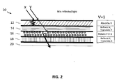
- Figures 1 and 2 show a first configuration assembly 10, which is designed for a dimming system and comprises of the following layers: an active polarizer 12 with an absorptive axis in the x-direction (when activated) at the viewing surface 13 of the device, adjacent a static reflective polarizer 14 with a reflective axis in the x-direction, adjacent an active polarization rotator 16, adjacent a static reflective polarizer 18 with a reflective axis in the y-direction.
- the active polarizer and the active polarization rotator may be independently operated.
- Unpolarized light 30 with both x and y polarizations is incident on the first active absorptive polarizer 12 oriented in the x-direction. With no voltage applied, the active absorptive polarizer 12 will have minimal effect on the incident polarizations. Therefore, both polarizations will predominantly pass through to the next surface.
- the light then impinges on the 1st static reflective polarized 14 oriented in the x-direction.
- the reflective polarizer 14 predominantly reflects the x-axis polarization of the light and predominantly transmits the y-direction polarization.
- the x-direction polarized light goes back through the active polarizer 12 unaltered and leaves the device. Therefore, approximately 50% of the incident unpolarized light is reflected within the first two layers.
- the y-direction polarized light that passed the first reflective polarizer 14 impinges on the active "polarizer rotator" or PR 1 (16).
- PR1 (16) does not alter polarization when in an unenergized state. Therefore the y-direction polarized light continues to the second static reflective polarizer 18. This polarizer is oriented in the y-direction and as such it will reflect the y-polarized light back.
- Unpolarized incident light with both x and y polarization is incident on the first active absorptive polarizer 12 oriented in the x-direction.
- the active absorptive polarizer 12 When a voltage is applied, the active absorptive polarizer 12 will behave in a manner similar to a conventional polarizer. Therefore, it will absorb x-direction polarization while allowing y-polarization to propagate.
- the first static reflective polarizer 14 will reflect any x-direction polarization. Therefore, x-polarization of the light 30 is predominantly extinguished.
- the y-direction polarization will be transmitted predominantly by both the first active polarizer 12 as well as the first static reflective polarizer 14. It then impinges on an activated polarization rotator 16.
- the polarization rotator 16 will rotate the propagating y-direction polarization to an x-direction polarization light.
- This x-direction polarized light then impinges on the second static reflective polarizer 18 which is set in the y-direction and therefore transmits x-direction polarized light.
- the resultant x-direction polarization light is predominantly propagated through.
- a beam block 20 can be used to extinguish this transmitted light. Therefore, both the x-direction and the y-direction polarization lights are predor inantly absorbed and no light, or only a minimal amount of light, is reflected back from the device.
- the device can have a variable reflectance (in the case of a reflective device) or a variable transmittance (in the case of a transmissive device).
- polarizer rotator 16 may be used. For example, either a TN-type or an ECB-type rotator can be used in the assembly 10. If an ECB-type rotator is used instead of the TN-type polarization rotator, a portion of the y-axis polarization light is reflected. The portion depends on the wavelength since complete polarization rotation will not occur across the entire visible spectrum. As such, there may be a hue to the reflection observed from such a dimming device. As before, application of a voltage lower than the max to the active polarizer 12 or the polarization rotator 16 can alter either the intensity or shift the color to a different region of the spectrum.
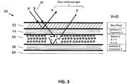
- FIG. 5 a second configuration designed for a dimming system is shown.
- the system 50 includes: an active polarizer 52 with absorptive axis in the x-direction when activated, adjacent a first static reflective polarizer 54 with a reflective axis in the x-direction, adjacent an active polarization rotator 56, followed by a second static reflective polarizer 58 with reflective axis in the x-direction.
- the active polarizer 52 and the active polarization rotator 56 may be independently operated.
- Fig. 3 and Table 3 show the device functioning in an OFF (v-0 or the voltage off) state.
- Unpolarized light 30 with both x and y polarization is incident on the first (active absorptive polarizer) oriented in the x-direction.
- the active absorptive polarizer 52 With no voltage applied, the active absorptive polarizer 52 will have minimal effect on the incident polarizations. Therefore, both polarizations will predominantly pass through to the next surface.
- the light then impinges on the 1 st static reflective polarizer 54 oriented in the x-direction.
- the reflective polarizer 54 predominantly reflects x-axis polarization of the light and predominantly transmits the y-direction polarization.
- the x-direction polarized light goes back through the active polarizer 52 unaltered and leaves the device. Therefore, approximately 50% of the unpolarized light is reflected within the first two layers.
- the y-direction polarized light passes through the first reflective polarizer and impinges on the active polarization rotator 56.
- the polarization rotator (PR2) 56 alters the polarization. Therefore the y-direction is now oriented to x-direction polarized light and continues to the second static reflective polarizer 58.
- the second reflective polarizer 58 is oriented in the x-direction and as such it will reflect the x-polarized light back. This light goes through the polarization rotator 56 and is again altered to Y direction.
- the y direction light continues to the first static reflector 54, which is oriented in the x-direction and will transmit the y-direction polarized light. Since the active polarizer 52 is in an OFF state, the y-direction polarized light continues though that layer and leaves the device. This means that the remaining 50% of the light is also reflected but after it traverses to the second reflective polarizer 58. Overall, both the x-direction and the y-direction polarized lights are predominantly reflected in the voltage off state.
- Unpolarized light with both x and y polarization is incident on the active absorptive polarizer 52 oriented in the x-direction.
- the active absorptive polarizer 52 With a voltage applied, the active absorptive polarizer 52 will behave in a manner similar to a conventional polarizer, which means it will absorb x-direction polarization while allowing y-polarization to propagate. Therefore, x-polarization of the light is predominantly extinguished.
- the y-direction polarization will be transmitted predominantly by both the first active polarizer 52 as well as the first static reflective polarizer 54.
- a beam block 20 can be used to extinguish this transmitted light. Therefore, both the x-direction and the y-direction polarization lights are predominantly absorbed and no light, or only a minimal amount of light, is reflected back from the device.
- the device can have a variable reflectance (in the case of a reflective device) or a variable transmittance (in the case of a transmissive device).
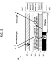
- Fig. 5 shows a configuration of a mirror device corresponding to the that shown in Example 1 but with the addition of a display device on the non-viewing side of the mirror.
- Fig. 5 shows how when a maximum voltage is applied (Vmax), the x-direction polarized light emitted from the display device 100 will be transmitted through the second static reflective polarizer 18 to the polarization rotator 16, which will rotate the polarization direction of the light to a y-direction. This y-direction light will then pass through the first static reflective polarizer 14 and the active polarizer 12 largely unaffected, to emerge through to the viewing surface 13 of the mirror 10.
- Vmax maximum voltage is applied
- the display light has the same polarization as the polarization axis of the absorptive polarizer.
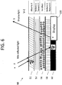
- Fig. 6 shows a configuration of a mirror corresponding to the that shown in Example 2 but with the addition of a display device on the non-viewing side of the mirror.
- Fig. 6 shows how when a maximum voltage is applied (Vmax), the y-direction polarized light emitted from the display device 200 will be transmitted through the second static reflective polarizer 58 to the polarization rotator 56, which will not affect the polarization direction of the light. This y-direction light will then pass through the first static reflective polarizer 54 and the active polarizer 52 largely unaffected, to emerge through to the viewing surface 53 of the mirror 50.
- Vmax maximum voltage is applied
- the display light has a polarization at right angles to the polarization axis of the absorptive polarizer.
- the dimmable mirror presently described can be used with various types of optical devices where attenuation of the reflectivity of the mirror is desired.
- Examples include general purpose mirror, vehicle (automotive) mirror, aircraft mirror, marine vehicle mirror, spacecraft mirror (e.g., rear-view mirror or side-view mirror), spectacles, binoculars, periscope, reflex camera, telescope, microscope, camera viewer (for locating an object before taking the picture of the object), view finder (for viewing an object while making a video recording of the object), and the like. It can also be used to block images or displays in applications such as mobile phone, LCDs, monitors, bill boards and the like.
Landscapes
- Physics & Mathematics (AREA)
- Nonlinear Science (AREA)
- General Physics & Mathematics (AREA)
- Optics & Photonics (AREA)
- Chemical & Material Sciences (AREA)
- Crystallography & Structural Chemistry (AREA)
- Mathematical Physics (AREA)
- Engineering & Computer Science (AREA)
- Multimedia (AREA)
- Mechanical Engineering (AREA)
- Liquid Crystal (AREA)
Description
- This application claims priority to, and any other benefit of,
U.S. Provisional Patent Application Serial No. 61/592,883 - The present invention relates to electronically dimmable reflective or transmissive optical devices using various reflective polarizer, absorptive polarizer and polarizer rotator configurations for use in vehicles, windows, visors, helmets, mobile phones and various other applications.
-
US 2004/100598 discloses a device capable of switching between a state that displays a high-quality image and a mirror status in which is obtained an easy-to-view reflection image, the mirror function portion including reflective polarization selection means, transmission polarization axis variable means and absorbing polarization selection means, the image display portion being disposed with image light-use polarization selection means. - In vehicles, drivers generally use an interior rearview mirror and two exterior side view mirrors (hereinafter referred to collectively as "rearview mirrors"). The rearview mirrors allow the driver to view scenes behind the vehicle without having to face in a rearward direction and to view areas around the vehicle that would otherwise be blocked by the vehicle structure. As such, these mirrors are an important source of information to the driver. Bright lights appearing in a scene behind the vehicle, such as from another vehicle approaching from the rear, may create glare in a rearview mirror that can temporarily visually impair or dazzle the operator. This problem is only aggravated under low ambient light conditions such as at night, when the eyes of the driver have adjusted to the darkness.
- Various solutions have evolved to deal with the problem of glare in rearview mirrors of vehicles. One conventional solution to this problem, used primarily with interior, center-mounted rear view mirrors, is to employ a prismatic mirror with a switch lever on the mirror housing. The switch can be manually moved between a daytime position, providing direct, normal intensity reflection from the mirror surface, and a nighttime position, providing a reduced intensity reflection. When the driver experiences glare, he manually changes the rearview mirror setting to low reflectivity. With the low intensity of light reflected to the driver, the intensity of reflected headlights from trailing vehicles is insufficient to impair the driver's vision. Once the glare is subsided, the driver can manually switch the rearview mirror back to high reflectivity. Difficulties with manually controlled mirrors include the glare experienced before the mirror could be switched, as well as driver distraction caused by finding and operating the switch lever.
- Other solutions include automatically dimming rearview mirrors which eliminate the need for the operator to manually switch the mirror. Improvements in glare reduction occurred when prismatic mirrors having two states were replaced with multi-state mirrors which include dimming elements capable of providing many levels of reflectivity reduction. One type of such multi-state automatically dimming rearview mirror is based on changes in the absorption spectra of some materials due to a change in the oxidation state induced by an external current flow. This effect is referred to in the literature as the electrochromic effect and such automatically dimming rearview mirrors are commonly termed electro-chromic mirrors. An electrochromic mirror includes an electrochromic medium connected between two electrodes. The electrochromic medium is responsive to external current generated by applying charge to a pair of electrodes. When a sufficient electrical current is applied across the electrodes of the automatically dimming rearview mirror, the electrochromic medium enters a tinted state by changing its spectral characteristics. However, electrochromic mirrors suffer from many limitations such as slow response rate, high temperature sensitivity, and high power consumption.
- Other known automatically dimming mirrors make use of the properties of liquid crystals. Liquid crystals have very fast response time, lower power consumption, and low temperature sensitivity in useable range. Application of an electric field reorients the liquid crystal molecules and changes their optical properties such as birefringence or absorption. In liquid crystal based dimming systems, when the molecules are in the realignment state, the light reflected from the mirrors is attenuated to a degree that is normally proportional to the applied electric field. Upon reducing or removing the applied electric field, the system returns to a normal, more transparent state. Using such mirrors, therefore, it is possible to obtain selectively a high or a low reflecting power, according to whether the electrical voltage applied to the liquid crystal is lower or greater than the threshold. However, liquid crystal based systems typically use static (not switchable) absorptive polarizers for light attenuation, which often reduces the reflectivity to <50% or <40%, even in the highly reflective state. This low reflectance automatically eliminates their use for many applications including rearview mirrors. More recently, guest host systems have been proposed to overcome this limitation. However, these systems still do not offer the high reflectance or wide swing in the reflectivity between the clear and the dark state that is achievable with electrochromic systems.
- To circumvent the issue associated with static absorptive polarizers, the use of switchable polarizers has been proposed. These can be reflective such as the device in
U.S. Patent No. 7,362,505 (Hikmet et al. ) or absorptive, such as the device inUS Pub. No. 2005/0057701 (Weiss ). However, switchable reflective polarizers based on cholesterics do not possess the optical or electrical characteristics needed for many dimmable mirror applications. For example, it is well known that switchable cholesteric polarizers have a high degree of haze in both transmissive and reflective states, which makes them unsuitable for optical applications, particularly when a single light source (such as a headlamp of a car) is used. Furthermore, they require high switching voltage and have an undesirably long relaxation time (e.g. several minutes) to the reflective state. These drawbacks make them unsuitable for dimmable mirror applications. - Absorptive active polarizers have been suggested for autodimming applications (see e.g. Weiss,
US Pub. No. 2005/0057701 ). In these systems, a single active polarizer is used to absorb both polarizations of the incident light. To achieve this, the combination of a quarterwave plate and a highly reflective, polarization independent mirror is used to rotate the polarization of unabsorbed light. The disadvantage of this system is that the reflection will not be uniform across the entire visible spectrum since quarterwave plates are wavelength and angular dependent. As such, the system will exhibit non-uniformity, especially in point source illumination conditions as observed with head lamps at night. In addition, these systems are not compatible for use with displays or other images. - Therefore, there is a need for dimming mirrors that can offer fast response time, low power consumption, and a low temperature sensitivity which also possess a high reflective state and a low dark state with potential for intermediate states.
- Similarly, there is a need for electronically dimmable transmissive devices, such as windows in a building, vehicle, airplane, etc., where the amount of light passing through the device can be controlled electronically. Thus, for example, a window can be dimmed in the summer to allow less sunlight into the interior of a building, while during winter months, it can be set to maximum transmissivity to allow more sunlight to enter the building. The present invention provides a description of various novel configurations of an electronically dimmable optical device that can be used in reflective and/or transmissive applications.
- According to the present invention, there is provided an electronically dimmable optical device as defined in
claim 1. - Preferably, the device further comprises a beam stop adjacent the second static reflective polarizer to absorb any light that reaches the beam stop.
- Conveniently, a. the active absorbing polarizer substantially absorbs an x-direction polarization of the incident light when activated by application of a voltage, wherein the active absorptive polarizer comprises a guest-host liquid crystal cell having a negative dielectric anisotropy host in a homeotropic alignment combined with a positive dichroic dye, b. the first static reflective polarizer reflects the x-direction polarization of the incident light, c. the active polarization rotator rotates the polarization axis of the incident light by 90° when activated by application of a voltage, d. the second static reflective polarizer reflects a y-direction polarization of the incident light, so that upon application of the voltage, the reflectivity of the optical device is reduced.
- Advantageously, a. the active absorbing polarizer substantially absorbs an x-direction polarization of the incident light when activated by application of a voltage wherein the active absorptive polarizer comprises a guest-host liquid crystal cell having a negative dielectric anisotropy host in a homeotropic alignment combined with a positive dichroic dye, b. the first and second static reflective polarizers reflect the x-direction polarization of the incident light, c. the active polarization rotator rotates the polarization axis of the incident light by 90° when in a non-activated state, so that upon application of a voltage, the reflectivity of the optical device is reduced.
- Preferably, the device is a dimmable mirror that reflects a selected wavelength of visible spectrum.
- Advantageously, the device is a dimmable mirror that absorbs a selected wavelength of the visible spectrum.
- Conveniently, the device is a transmissive device that has minimum transmissivity when the device is not activated by application of a voltage.
- Preferably, the reflectivity/transmissivity of the device is controlled automatically, manually, or with a combination of both automatic and manual controls.
- Advantageously, the device has one or more of the following characteristics: a) reflects more than 50% of incident light when it is in its maximum reflectivity state; b) reflects less than 20% of incident light when it is in its minimum reflectivity state; c) has a swing (or contrast) between its maximum and minimum reflective states of more than 50%.
- Conveniently, a selected polarization level selectable by controlling the voltage at said active absorptive polarizer and wherein setting said active absorptive polarizer to said selected polarization level determines the brightness of a reflected image produced by said device.
- Preferably, the optical device further comprises a controller, controlling said active absorptive polarizer, wherein said controller is coupled with said active absorptive polarizer, wherein said active absorptive polarizer is divided into two or more sections, and wherein said controller sets each of said sections to a respective polarization level.
- Conveniently, the optical device further comprises at least one light detector coupled with said controller, wherein said at least one light detector provides at least one light-intensity value, wherein said controller sets said active absorptive polarizer to a selected polarization level according to said at least one light-intensity value.
- Advantageously, the device further comprises a display (100) placed on a non-viewing side of the optical device and wherein at least a portion of light emitted from the display is transmitted to a viewing surface of the optical device.
- The present invention also provides the optical device for use as a rearview or side-view mirror of a vehicle.
- Other features; details, utilities, and advantages of the present invention may be apparent from the following more particular written description of various embodiments of the invention as further illustrated in the accompanying drawings and defined in the appended claims.
- Features and advantages of the invention will become apparent from the following detailed description made with reference to the accompanying drawings, wherein:
-
FIG 1 is a schematic cross-sectional view of a portion of an optical device according to a first embodiment when the device is in a voltage OFF state; -
FIG 2 is a schematic cross-sectional view of a portion of the optical device according to the first embodiment when the device is in a maximum voltage ON state; -
FIG 3 is a schematic cross-sectional view of a portion of an optical device according to a second embodiment when the device is in a voltage OFF state; -
FIG 4 is a schematic cross-sectional view of a portion of the optical device according to the second embodiment when the device is in a maximum voltage ON state; -
FIG 5 is a schematic cross-sectional view of a potion of an electronically dimmable mirror used with a display; -
FIG 6 is a schematic cross-sectional view of a potion of another example of an electronically dimmable mirror used with a display. - Herein described is an electronically dimmable optical device having, in sequence, the following layers: an active (electrically switchable) absorptive polarizer, a first static (non-switchable) reflective polarizer, an active (electrically switchable) polarization rotator, and a second static (non-switchable) reflective polarizer. The device is configured so that the reflectivity of the device can be controlled by application of a voltage to the active layers.
- In one embodiment, the device is primarily a reflective device and can additionally include a beam stop.
- In some embodiments, the layers are configured so that the device, when in an unenergized state, will reflect substantially all incident light ("clear mirror state"), but when energized, will absorb a portion of incident light, leading to a dimmed reflected image ("dark mirror state"). In some embodiments, when a maximum voltage is applied, the device can be made to substantially absorb 100% of incident light.
- Accordingly, in case of a reflective device such as a mirror, with the application of a fixed or variable voltage, the mirror will have one or more variable reduced reflectivity states, where it will absorb a variable portion (up to substantially all) of the x and y direction polarization of the incident light.
- In a transmissive device embodiment (such as a window, visor, helmet, view finder of a camera, etc.), the device will not include a beam stop, so that a viewer is able to see though the device.
- It should also be noted that in the transmissive device, the device may be used in either direction, i.e. the active polarizer layer may be adjacent the entrance surface of the device or, vice versa, the second passive reflective layer may be adjacent the entrance surface.
- In a transmissive embodiment, the active polarizer and active polarization rotator may be constructed so that the device is most transmissive when no voltage is applied, and is most reflective when a voltage is applied. However, in other embodiments, the reverse can be the case, so active layers are constructed in a way that makes the device most transmissive when a voltage is applied and most reflective (has reduced transmissivity) when no voltage is applied (unenergized state).
- When used as a transmissive device, the application of a fixed or variable voltage will alter the amount of light that passes through the device to reach a viewer.
- The voltage applied to the dimming device assembly can control the dimming effect and can be regulated in a manner such that the reflectivity, or transmissivity, of the device is reduced to suit the prevailing conditions. This can be accomplished manually or automatically, by using one or more light sensors connected to an electric control system which react either to the brightness of the surroundings, or the intensity of the light incident on the front of the device, or both. Thus, the amount of dimming may be varied either manually, automatically, or both.
- In accordance with a further aspect of the invention, there is provided a method for reflecting light at variable intensity by application of a voltage to an electronically dimmable optical device. The method includes the process of directing incident light toward a device having an active absorptive polarizer at its viewing surface, followed by a first static (non-switchable) reflective polarizer, an active (electrically switchable) polarization rotator, and a second static (non-switchable) reflective polarizer and finally a beam stop, configured such that when the device is in an unenergized state, substantially all of the light incident on the viewing surface is reflected, but when a maximum voltage is applied to the active polarizer and the active polarization rotator, substantially all of the light incident on the viewing surface is absorbed, thus reducing the intensity of the reflected light. The level of reflectivity of the device can be varied by applying a variable voltage between a zero voltage and maximum voltage settings.
- In accordance with another aspect of the invention, there is provided a method for transmitting light at variable intensity by application of a voltage to an electronically dimmable optical device. The method includes the process of directing incident light toward a device having an active absorptive polarizer adjacent a first static (non-switchable) reflective polarizer, adjacent an active (electrically switchable) polarization rotator, adjacent a second static (non-switchable) reflective polarizer, and applying voltage to the device to alter the amount of light transmitted or reflected by the device.
- In some embodiments of the transmissive method, the configuration of the layers is such that the method includes directing incident light toward an active absorptive polarizer layer first, before it passes though the other layers (i.e., the active absorptive polarizer is adjacent the entrance surface of the device). In other embodiments, the configuration of layers is such that the method includes directing incident light toward the second reflective polarizer first, before it passes though the other layers (i.e. the second reflective polarizer is adjacent the entrance surface of the device).
- In some embodiments, the method includes reducing the transmissivity of the device by applying a voltage, so that when the device is in an unenergized state, a portion of the light incident on the entrance surface is transmitted through the device, but when a maximum voltage is applied to the active polarizer and/or the active polarization rotator, substantially all of the light incident on the entrance surface is reflected, thus reducing the intensity of the transmitted light.
- In other embodiments, the method includes increasing the transmissivity of the device by applying a voltage, so that when the device is in an energized state, a portion of the light incident on the entrance surface is transmitted through the device, but when no voltage is applied to the active polarizer and/or the active polarization rotator, substantially all of the light incident on the entrance surface is reflected, thus reducing the intensity of the transmitted light.
- The level of transmissivity of the device can be varied by applying a variable voltage between a zero voltage and maximum voltage settings.
- It should be noted that when the different layers are described as "adjacent" one another, it is referring to the sequence of layers. Thus, it may be possible for other layers, films or materials to be interposed between the active polarizer, first passive reflective polarizer, active polarization rotator and second passive reflective polarizer layers without disturbing the sequence of their arrangement. For example, an adhesive or other layer or film may be disposed between the different layers.
- In some embodiments, the method includes the following configuration: setting an active polarizer to be in a non-absorptive state when not energized, and to absorb a portion of the x-direction polarization of incident light and transmit the y-direction polarization when energized by application of a voltage. Setting the first and second static reflective polarizers to reflect different 90° polarizations of light, such that the first reflective polarizer will reflect the same direction polarization that the active polarizer absorbs (i.e. the x-direction polarization) and the second reflective polarizer will reflect the orthogonally opposite direction polarization of light (i.e. the y-direction polarization). The method further includes setting the active polarization rotator to have no effect when non-energized but to rotate the polarization direction of light by up to 90° (i.e. x to y or y to x) when energized. This configuration will effectively reflect substantially 100% of light incident on a device's viewing or entrance surface when no voltage is applied. The level of reflectivity of the device can be varied by applying a variable voltage between a zero voltage and maximum voltage settings.
- In other embodiments, the method includes the following configuration: setting the viewing or entrance surface active polarizer to be in a non-absorptive state when not energized, and to absorb a portion of the x-direction polarization of incident light and transmit the y-direction polarization when energized by application of a voltage. Setting the first and second static reflective polarizers to reflect the same x-direction polarization of light. The method further includes setting the active polarization rotator to have no effect when energized by a maximum voltage but to rotate the polarization direction of light by 90° (i.e. x to y or y to x) when in a non-energized state. This configuration will also effectively reflect substantially 100% of incident light on a device's viewing or entrance surface when a maximum voltage is applied. The level of reflectivity of the device can be varied by applying a variable voltage between a zero voltage and maximum voltage settings.
- In some embodiments of the reflective device according to the invention, the device will have the ability to reflect from substantially 100% of incident light (when V=0 or when the mirror is "clear") to substantially 0% of the incident light (when Vmax is applied or when the mirror is "dark"), or any % of light when in a variable in-between state. Thus the reflectivity swing (or contrast) between the maximum and minimum reflective states can be set to be more than 50%. This is because the mirror is able to reflect more than 50% of incident light when it is in its maximum reflectivity state. This effect is not achievable when a regular polarizer is used with a mirror (as in some prior art devices) because the polarizer will effectively absorb 50% of incident light, thus always less than 50% of the incident light will be reflected.
- It is also noteworthy that the present arrangement allows for use of a display behind the reflective device or mirror. Thus, also contemplated herein is a device and method which further include allowing a display light emitted from a display device placed on the back surface of the mirror to be transmitted to the viewing surface of the mirror.
- In some embodiments, to achieve this effect, a portion of the conductive layer (such as the ITO, etc.) that is applied to the active polarizer, the active polarization rotator or both, can be etched away or otherwise removed in such a manner, so that two regions are present that can operate independently. Therefore, when a voltage is applied to one region, dimming the mirror's reflectivity in that region, the display light from the other region is not affected or dimmed if so desired. Accordingly, in some examples, the active absorptive polarizer is divided into two or more sections, and the controller sets each of the sections to a respective polarization level. In some examples, the display area is smaller than, and occupies a small portion, of the viewing surface of the mirror.
- Alternatively, the mirror can have a display region without the need for etching of the conductive layer(s). In such an embodiment, the reflectivity of the mirror is decreased and the display light is transmitted to the viewing surface with the application of voltage. Accordingly, not only is it possible to use only a portion of the viewing area of the mirror for display purposes, but it is possible to use the entire viewing area of the mirror to display an image (see, e.g.
Figs. 5-6 ). - The display can be tuned so that it can be visible when the mirror is in its minimum reflective state, when the mirror is in its most reflective state, and/or while the mirror is in an intermediate reflective state, or any combination of the above.
- Unless specifically defined otherwise herein, the definitions for optical parameters such as linear, circular and unpolarized light are the same as those in " Principles of Optics Electromagnetic Theory of Propagation, Interference and Diffraction of Light", Max Born, et al., Cambridge University Press; 7th edition (October 13, 1999). Similarly, all liquid crystal terminology which is not specifically defined herein is to have the definition as used in Liquid Crystals Applications and Uses, vol.3, edited by B. Bahadur, published by World Scientific Publishing Co. Pte. Ltd., 1992 ("Bahadur").
- An "absorptive polarizer" is a polarizer that will absorb a selected polarization of light. An absorptive polarizer will have two axes, an absorptive axis and a transmissive axis, which are at right angles to each other. The polarization of the light that is parallel to the absorptive axis is absorbed more than the polarization parallel to the transmissive axis.
- For example, an "absorptive polarizer with an axis in the x-direction" means that the polarizer will substantially absorb the x-direction polarization of light while substantially allowing y-polarization to propagate. Vice versa, an absorptive polarizer with an axis in the y-direction means that the polarizer will substantially selectively absorb y-polarized light and substantially transmit x-polarized light.
- It should be noted that absorptive circular polarizers exist and are typically constructed by using a linear polarizer in combination with a quarter wave retarder. Once light is polarized by the polarizer, the quarter wave plate induces a π/2 phase retardation which turns a linear polarization to a circular polarization.
- An "active" polarizer, used interchangeably with an "active absorptive polarizer", refers to a polarizer that will alter its absorption of the selected polarization of light depending on the applied voltage. Thus, when in an unenergized or non-active state, the polarizer will not preferentially absorb either polarization and will transmit light of either polarization.
- A controller coupled with the active polarizer controls the polarization: in one embodiment, the polarizer is operated in an ON or OFF state. In other embodiments, the polarizer can be set to apply a variable polarization absorption level with the controller setting a selected polarization level. In some example, the polarization level of the active absorptive polarizer is selected by controlling the voltage applied to the active absorptive polarizer. Accordingly, setting the active absorptive polarizer to the selected polarization level determines the brightness of the image produced by the device. Thus, the device can further include a controller for application of voltage to the device and the controller is coupled with the active absorptive polarizer.
- The reflectivity and/or transmissivity of the devices o can be controlled automatically, manually, or with a combination of both automatic and manual controls.
- A "reflective polarizer" is a polarizer that will reflect a selected polarization of light more than the other. For example, a "reflective polarizer with a reflective axis in the x-direction" means that the reflective polarizer will reflect the x-direction polarization of incident light more than the other y-direction polarization. Vice versa, a "reflective polarizer with a reflective axis in the y-direction" means that the reflective polarizer will reflect the y-direction polarization of incident light more than the other x-direction polarization
- A "passive" or "static" reflective polarizer will always have the same reflective properties, whether voltage is applied to the device or not.
- An "active polarization rotator" refers to a device where application of a voltage to the device alters the polarization direction of two linearly polarized components of the incoming light by a value between 0 and 90°, changing it so that light exiting the polarizer rotator is changed from a substantially first direction to a substantially second direction polarization within a selected wavelength region. Thus, for example, an x-direction polarized light entering the polarizer rotator will be turned into a y-direction polarized light before exiting the rotator, and vice versa, a y-direction polarization will be turned into an x-direction polarized light when a maximum voltage is applied. The fully activated active polarizer rotator described herein will rotate the polarization direction of the light by 90°, and as such, acts like a half wave, ½ λ plate.
- As described herein, the active polarization rotator may function in two ways: in some examples, polarization rotation occurs when the rotator is in the energized state, in other examples, polarization rotation occurs when the rotator or device is in an unenergized (non-activated) state.
- A controller coupled with the active polarization rotator alters the amount of one polarization with respect to the other. In the extreme case, the polarization would be rotated by a full 90 degrees. However, intermediate states can be achieved by using voltages which are between the zero and max voltage states.
- The term "viewing surface" refers to the front surface of a mirror and is the surface closest to the viewer's eye. In contrast, the "non-viewing" side of a mirror refers to the back of the mirror.
- In a transmissive device, the term "entrance surface" refers to the surface of the device where incident light (e.g. sunlight) enters the device. In the case of a window, the entrance surface is the outside surface of the mirror.
- The terms "x" and "y" direction polarization are arbitrary and refer to a first and second orthogonal or circular polarization direction of light which are at right angles to each other. They are used, instead of stating for example a "first" and a "second" polarization direction only to simplify the description of the invention do not refer to any fixed values of direction.
- Conventionally, properties of a light are characterized by its (i) propagation direction, denoted by the wave vector, K, (ii) wavelength denoted by λ, (iii) two orthogonal polarizations direction, P1 and P2 , (iv) polarization mode, which can be unpolarized, circular/elliptical or linear , and (iv) by energy being carried within each polarization, denoted here by I1 and I2.
- Generally, the term polarization refers to the oscillation direction of the electric field of the incident light. The difference between linear, circular and unpolarized light is in how a unique representation of the polarization is determined. In particular, in linearly polarized systems, the oscillation occurs in a single axis direction, x or y. In circularly polarized light, the oscillation rotates in time or space tracing out a circle or ellipse. In unpolarized light, the oscillation direction cannot be uniquely defined. Unpolarized light is viewed as a light in which (i) there is an equal amount of both orthogonal polarizations and (ii) the direction of the polarization at any given time is random and cannot be defined.
- It is well known that unpolarized light can be identically viewed as composed of two orthogonal, circularly polarized lights (right- or left- handed) or of two orthogonal linearly polarized lights (x and y direction). In a rear-view mirror embodiment, since light from head lamps are typically unpolarized, a dimming mirror should preferably be capable of reducing the energy in both polarizations. In this application, for descriptive purposes, light is referred to as polarized in two directions to simplify the explanation of how the device works. It should be understood, however, that the devices and principles described herein will apply to all light. "Light" in this application refers to visible light with a wavelength of about 380-750 nm.
- As presented herein, the unpolarized light is considered to be composed of two linear polarizations in an x and a y direction and propagating in a z direction. Furthermore, it is noted that a reflective polarizer has also two axes, x and y. The reflective polarizer operates in a manner such that if the polarization axis of the light matches the axis of the reflective polarizer, then that polarization is predominantly reflected. If the polarization axis of the light is perpendicular to that of the reflective polarizer, then that component is predominantly transmitted.
- It is noted that in the case of circular light, the x and y refer to the handedness of the polarization rather than fixed directions in space. Therefore x, for example, will denote right circular and y will denote left circular. As in the case of linearly polarized light, the unpolarized light will be considered to be composed of equal amounts of left and right circularly polarized amounts. The reflective polarizer, in that case, will reflect either the right- or the left-circular polarization depending on its configuration and will transmit the other polarization, left- or right-, respectively.
- The reflective polarizer is considered to be "static" or "passive" in that its polarizing characteristics cannot be altered by application of a voltage.
- In the devices described herein, a switchable polarizer can be provided by a using a Guest-Host system: dichroic dye molecules are dissolved in a nematic or chiral nematic liquid crystal (LC) layer. The dye molecules (Guest) are oriented by the presence of the LC molecules (Host). Applying an electric field to the layer will re-orient the LC molecules and the dye molecules will follow this re-orientation. Such a stack will either absorb light of one polarization or be transparent. Suitable dyes that can be added to liquid crystal mixtures for this purpose are known in the art. The degree of preferential absorption of one polarization with respect to the other is dependent on the applied voltage.
- The absorptive polarizer of the present invention is assumed to be active in that its polarizing/absorptive properties can be altered by application of an external electrical field (voltage). Furthermore, this active polarizer is based on a guest-host liquid crystal system or cell that includes a negative dielectric anisotropy host combined with a positive dichroic dye in a homeotropically aligned cell. Alternatively, a positive dielectric anisotropy host can be used with positive dichroic dyes in a plannar aligned cell. For autodimming reflective devices such as those used in the automobiles, the homeotropic based system is better suited to provide substantially 100% reflectance in the voltage off state. The liquid crystal cell is designed such that application of a voltage results in a change in transmission of the light through the cell. More specifically, application of a voltage will preferentially increase the absorption of one polarization more than the other. The axis of the preferentially absorbed polarization matches the absorptive axis of the active polarizer.
- The "polarization rotator film" or layer, which rotates the polarization of incident light as it propagates through the medium, can be a broad band rotator device such as a twisted nematic (TN)-based device or a more wavelength selective device as used in electronically controlled birefringence (broadly classified as ECB) -based devices. This film is assumed to be active in that its performance depends on an applied voltage. It is well known that for the correct performance, the axis of the polarization rotator will be at a specific angle relative to the axis of the polarization of the light. For example, in a broad band device, the axes of the TN are parallel to the polarization axes of the incident light. The polarization rotator can be designed so that it performs the polarization rotation when activated by application of an electric field or voltage. This is achieved by, for example, using negative dielectric anisotropy liquid crystals along with a homeotropic alignment layer, or vice versa by using a positive dielectric anisotropy liquid crystal and a planar alignment layer. In general, the application of voltage alters the orientation of the liquid crystal and hence the overall birefringence of the system. This change can be positive in the former or negative in the latter. Therefore, for example, in a positive dielectric anisotropy liquid crystal and a planar alignment layer, application of voltage reduces the birefringence observed by different polarizations and hence reduces the phase retardation between the two polarizations. If the birefringence is substantially close to zero at maximum applied voltage, then no phase retardation is observed and hence no polarization rotation occurs in the cell.
- The active polarization rotator is defined such that the polarization rotation occurs in the energized state as PR1 and the active polarization rotator in which the polarization rotation occurs in the unenergized state as PR2. It is well known in the art that to achieve proper polarization rotation, the birefringence and the thickness of the layer must be properly selected as discussed in, for example, Liquid Crystals Applications and Uses, vol.3, edited by B. Bahadur, published by World Scientific Publishing Co. Pte. Ltd., (1992). The choice in use of a TN-type configuration or ECB-type depends on the device preference such as color selectivity but will not alter the overall configuration schematic presented.
- A beam stop layer can be utilized for the reflective embodiments, such as, e.g. in autodimming mirror applications. This can be any material which has low reflectance and predominantly absorbs the light that impinges upon it from the other layers stated above. Its function is to stop additional reflection of any portion of the light reaching it once it passes the last optical element. Examples of this include tinted paper or other materials, absorbers, polarizers and the like.
- In some applications, it is desirable to have a dimming mirror that can also be used for display purposes, where in addition to the reflected image, a displayed image from a backlight display device is visible to a viewer. Accordingly, another embodiment of the dimming mirror includes a display device placed on at least a portion of the mirror's non-viewing side so that part of the mirror is used as a display (the "display area") while the reflective function remains in the remainder part of the mirror (the "reflective area"). The beam stop layer may, itself, have the additional function of displaying an image, or may have a polarization dependent performance. In some embodiments, the display area is smaller than the reflective area. In other embodiments, the display area covers the entire reflective area. The mirror can be configured so that when the display device is in use, at least a portion of light emitted from the display is transmitted to the display area portion of the viewing surface of the mirror.
- In other aspects, the transparent conductor layer(s) may be etched in a pattern that will allow independent driving of the two or more different regions of the mirror. In that case, part of the mirror may be in one operational state while the other sections remain in a different state. The etched pattern can be selected to expose the display area or an image or writing or alike.
- Some proposed configurations for an electronically dimmable optical device are presented below. There are several geometries that can be utilized depending on the performance desired. For the sake of illustration, linearly polarized systems are used but it should be noted that polarizers and active phase retarders can be used to allow for circularly or other polarization modes of light to be utilized according to the same principles.
-
Figures 1 and2 show afirst configuration assembly 10, which is designed for a dimming system and comprises of the following layers: anactive polarizer 12 with an absorptive axis in the x-direction (when activated) at the viewing surface 13 of the device, adjacent a staticreflective polarizer 14 with a reflective axis in the x-direction, adjacent anactive polarization rotator 16, adjacent a staticreflective polarizer 18 with a reflective axis in the y-direction. It should be noted that the active polarizer and the active polarization rotator may be independently operated. -
Fig. 1 and Table 1 show the device functioning in an OFF (V=0 or voltage-off) state. Unpolarized light 30 with both x and y polarizations is incident on the first activeabsorptive polarizer 12 oriented in the x-direction. With no voltage applied, the activeabsorptive polarizer 12 will have minimal effect on the incident polarizations. Therefore, both polarizations will predominantly pass through to the next surface. The light then impinges on the 1st static reflective polarized 14 oriented in the x-direction. Thereflective polarizer 14 predominantly reflects the x-axis polarization of the light and predominantly transmits the y-direction polarization. The x-direction polarized light goes back through theactive polarizer 12 unaltered and leaves the device. Therefore, approximately 50% of the incident unpolarized light is reflected within the first two layers. The y-direction polarized light that passed the firstreflective polarizer 14 impinges on the active "polarizer rotator" or PR 1 (16). As stated before, PR1 (16) does not alter polarization when in an unenergized state. Therefore the y-direction polarized light continues to the second staticreflective polarizer 18. This polarizer is oriented in the y-direction and as such it will reflect the y-polarized light back. This reflected light goes through thepolarizer rotator 16 again unaffected and continues to staticreflective polarizer 14, which is oriented in the x-direction. Again, the y-direction polarized light is transmitted back through thestatic reflector 14. Since theactive polarizer 12 is in an unenergized state, the y-direction polarized light continues through that layer and leaves the device. This means that the remaining 50% of the incident light is also reflected but after it traverses to the secondreflective polarizer 18. Overall, both the x-direction and the y-direction polarized lights are predominantly reflected in the voltage-off state (close to 100% reflection). -
Fig. 2 and Table 2 show device functioning in a Maximum Voltage (Vmax or V=1) state. Unpolarized incident light with both x and y polarization is incident on the first activeabsorptive polarizer 12 oriented in the x-direction. When a voltage is applied, the activeabsorptive polarizer 12 will behave in a manner similar to a conventional polarizer. Therefore, it will absorb x-direction polarization while allowing y-polarization to propagate. The first staticreflective polarizer 14 will reflect any x-direction polarization. Therefore, x-polarization of the light 30 is predominantly extinguished. The y-direction polarization will be transmitted predominantly by both the firstactive polarizer 12 as well as the first staticreflective polarizer 14. It then impinges on an activatedpolarization rotator 16. Thepolarization rotator 16 will rotate the propagating y-direction polarization to an x-direction polarization light. This x-direction polarized light then impinges on the second staticreflective polarizer 18 which is set in the y-direction and therefore transmits x-direction polarized light. As such, the resultant x-direction polarization light is predominantly propagated through. - In a reflective (e.g. mirror) application, a
beam block 20 can be used to extinguish this transmitted light. Therefore, both the x-direction and the y-direction polarization lights are predor inantly absorbed and no light, or only a minimal amount of light, is reflected back from the device. - In a transmissive application, approximately 50% of light is transmitted through.
- If a voltage lower than the Vmax is used on either the
active polarizer 12 or thepolarization rotator 16, a portion of light is reflected depending on the voltage applied. As such the device can have a variable reflectance (in the case of a reflective device) or a variable transmittance (in the case of a transmissive device). - Many types of
polarizer rotator 16 may be used. For example, either a TN-type or an ECB-type rotator can be used in theassembly 10. If an ECB-type rotator is used instead of the TN-type polarization rotator, a portion of the y-axis polarization light is reflected. The portion depends on the wavelength since complete polarization rotation will not occur across the entire visible spectrum. As such, there may be a hue to the reflection observed from such a dimming device. As before, application of a voltage lower than the max to theactive polarizer 12 or thepolarization rotator 16 can alter either the intensity or shift the color to a different region of the spectrum.Table1: Device in its inactive, maximum reflectivity state (V=0) Active Polarizer First Reflective Polarizer Active Polarization rotator Second Reflective Polarizer Beam Stop No effect Reflect X No effect Transmit X Absorbs all light Transmit Y Reflect Y Transmits both polarizations Reflects X Transmits both polarizations Reflects Y Table2: Device in its active, minimum reflectivity state (Vmax) Active Polarizer First Reflective Polarizer Active Polarization rotator Second Reflective Polarizer Beam Stop Absorbs X Reflect X Rotates 90° Transmit X Absorbs all light Transmits Y Transmit Y X→ Y, Y→ X Reflect Y Extinguishes X Y → X Transmits X Extinguishes X - In another embodiment, shown in
Figures 3 and4 , a second configuration designed for a dimming system is shown. Thesystem 50 includes: anactive polarizer 52 with absorptive axis in the x-direction when activated, adjacent a first staticreflective polarizer 54 with a reflective axis in the x-direction, adjacent anactive polarization rotator 56, followed by a second staticreflective polarizer 58 with reflective axis in the x-direction. It should be noted that theactive polarizer 52 and theactive polarization rotator 56 may be independently operated. -
Fig. 3 and Table 3 show the device functioning in an OFF (v-0 or the voltage off) state. Unpolarized light 30 with both x and y polarization is incident on the first (active absorptive polarizer) oriented in the x-direction. With no voltage applied, the activeabsorptive polarizer 52 will have minimal effect on the incident polarizations. Therefore, both polarizations will predominantly pass through to the next surface. The light then impinges on the 1st staticreflective polarizer 54 oriented in the x-direction. Thereflective polarizer 54 predominantly reflects x-axis polarization of the light and predominantly transmits the y-direction polarization. The x-direction polarized light goes back through theactive polarizer 52 unaltered and leaves the device. Therefore, approximately 50% of the unpolarized light is reflected within the first two layers. The y-direction polarized light passes through the first reflective polarizer and impinges on theactive polarization rotator 56. When no voltage is applied, the polarization rotator (PR2) 56 alters the polarization. Therefore the y-direction is now oriented to x-direction polarized light and continues to the second staticreflective polarizer 58. The secondreflective polarizer 58 is oriented in the x-direction and as such it will reflect the x-polarized light back. This light goes through thepolarization rotator 56 and is again altered to Y direction. The y direction light continues to the firststatic reflector 54, which is oriented in the x-direction and will transmit the y-direction polarized light. Since theactive polarizer 52 is in an OFF state, the y-direction polarized light continues though that layer and leaves the device. This means that the remaining 50% of the light is also reflected but after it traverses to the secondreflective polarizer 58. Overall, both the x-direction and the y-direction polarized lights are predominantly reflected in the voltage off state. -
Fig. 4 and Table 4 show thedevice 50 functioning in a Maximum Voltage (Vmax or V=1) minimum reflectivity state. Unpolarized light with both x and y polarization is incident on the activeabsorptive polarizer 52 oriented in the x-direction. With a voltage applied, the activeabsorptive polarizer 52 will behave in a manner similar to a conventional polarizer, which means it will absorb x-direction polarization while allowing y-polarization to propagate. Therefore, x-polarization of the light is predominantly extinguished. The y-direction polarization will be transmitted predominantly by both the firstactive polarizer 52 as well as the first staticreflective polarizer 54. It then impinges on an activatedpolarization rotator 56. The polarization rotator in its active state will not rotate the polarization and so the y-direction polarization light will pass through unaffected. This y-direction polarized light then impinges on the second staticreflective polarizer 58 which is set in the x-direction. As such, the y-direction polarization light will pass thorough. - In a reflective (e.g. mirror) application, a
beam block 20 can be used to extinguish this transmitted light. Therefore, both the x-direction and the y-direction polarization lights are predominantly absorbed and no light, or only a minimal amount of light, is reflected back from the device. - In a transmissive application, approximately 50% of light is transmitted through.
- If a voltage lower than the Vmax is used on either the
active polarizer 12 or thepolarization rotator 16, a portion of light is reflected. As such the device can have a variable reflectance (in the case of a reflective device) or a variable transmittance (in the case of a transmissive device).Table 3: Device in its inactive, maximum reflectivity state (V=0) Active Polarizer First Reflective Polarizer Active Polarization rotator Second Reflective Polarizer Beam Stop No effect Reflect X Rotates 90° Reflect X Absorbs all light Transmit Y X→ Y, Y→ X Transmit Y Transmits both polarizations Reflects X Y → X Reflects X Y ← X 
Table 4: Device in its active, minimum reflectivity state (Vmax) Active Polarizer First Reflective Polarizer Active Polarization rotator Second Reflective Polarizer Beam Stop Absorbs X Reflect X No effect Reflect X Absorbs all light Transmits Y Transmit Y Transmit Y Extinguishes X Transmits Y Transmits Y Transmits Y Extinguishes Y -
Fig. 5 shows a configuration of a mirror device corresponding to the that shown in Example 1 but with the addition of a display device on the non-viewing side of the mirror. -
Fig. 5 shows how when a maximum voltage is applied (Vmax), the x-direction polarized light emitted from thedisplay device 100 will be transmitted through the second staticreflective polarizer 18 to thepolarization rotator 16, which will rotate the polarization direction of the light to a y-direction. This y-direction light will then pass through the first staticreflective polarizer 14 and theactive polarizer 12 largely unaffected, to emerge through to the viewing surface 13 of themirror 10. - In this configuration, the display light has the same polarization as the polarization axis of the absorptive polarizer.
-
Fig. 6 shows a configuration of a mirror corresponding to the that shown in Example 2 but with the addition of a display device on the non-viewing side of the mirror. -
Fig. 6 shows how when a maximum voltage is applied (Vmax), the y-direction polarized light emitted from thedisplay device 200 will be transmitted through the second staticreflective polarizer 58 to thepolarization rotator 56, which will not affect the polarization direction of the light. This y-direction light will then pass through the first staticreflective polarizer 54 and theactive polarizer 52 largely unaffected, to emerge through to the viewing surface 53 of themirror 50. - In this configuration, the display light has a polarization at right angles to the polarization axis of the absorptive polarizer.
- It is noted that the dimmable mirror presently described can be used with various types of optical devices where attenuation of the reflectivity of the mirror is desired. Examples include general purpose mirror, vehicle (automotive) mirror, aircraft mirror, marine vehicle mirror, spacecraft mirror (e.g., rear-view mirror or side-view mirror), spectacles, binoculars, periscope, reflex camera, telescope, microscope, camera viewer (for locating an object before taking the picture of the object), view finder (for viewing an object while making a video recording of the object), and the like. It can also be used to block images or displays in applications such as mobile phone, LCDs, monitors, bill boards and the like.
- Although the description above contains many specificities, and reference to one or more individual embodiments, these should not be construed as limiting the scope of the invention but rather construed as merely providing illustrations of certain exemplary embodiments of this invention.
Claims (14)
- An electronically dimmable optical device (10) configured to act upon incident light having two orthogonal polarization directions, comprising:a viewing surface, on which the incident light falls, arranged closest to the viewer's eye formed by an active absorbing polarizer (12) that is electrically switchable having an absorptive axis, followed bya first static reflective polarizer (14) adjacent the active absorbing polarizer (12) and having a first reflective axis, the first static reflective polarizer (14) configured to reflect one of the two orthogonal polarization directions of the incident light that is parallel to said reflective axis more than the other polarization direction; followed byan active polarization rotator (16) that is electrically switchable adjacent the first static reflective polarizer (14) and capable of altering the polarization direction of the two orthogonal polarization directions by a value between 0 and 90° including both end values; and followed bya second static reflective polarizer (18) adjacent the active polarization rotator (16) and having a second reflective axis, configured to reflect the other of the two orthogonal polarization directions of the incident light that is parallel to said second reflective axis more than the one of the two orthogonal polarization directions;characterised in that the active absorbing polarizer in configured so that when activated it substantially absorbs a selected polarization of the incident light that is parallel to said absorptive axis, and when not activated it transmits light of either polarization direction, and in that the device is configured so that it has a maximum reflectivity when no voltage is applied to the active absorbing polarizer and active polarization rotator and a minimum reflectivity when a suitable voltage is applied to each of said active absorbing polarizer and active polarization rotator.
- The optical device of claim 1, wherein the device further comprises a beam stop (20) adjacent the second static reflective polarizer to absorb any light that reaches the beam stop.
- The optical device of claim 1 or 2, wherein the two orthogonal polarization directions of the incident light are along an x- an a y-axis, respectively, in a plane of the device, andthe active absorbing polarizer substantially absorbs the x-direction polarization of the incident light when activated by the application of a voltage, wherein the active absorptive polarizer comprises a guest-host liquid crystal cell having a negative dielectric anisotropy host in a homeotropic alignment combined with a dichroic dye having positive dichroism,the first static reflective polarizer reflects the x-direction polarization of the incident light,the active polarization rotator rotates the polarization axis of the incident light by 90° when activated by application of a voltage,the second static reflective polarizer reflects the y-direction polarization of the incident light,so that upon the application of a voltage to each of said active absorbing polarizer and active polarization rotator, the reflectivity of the optical device is reduced.
- The optical device of claim 1 or 2, wherein the two orthogonal polarization directions of the incident light are along an x- and a y-axis, respectively, in a plane of the device, andthe active absorbing polarizer substantially absorbs the x-direction polarization of the incident light when activated by the application of a voltage wherein the active absorptive polarizer comprises a guest-host liquid crystal cell having a negative dielectric anisotropy host in a homeotropic alignment combined with a dichroic dye having positive dichroism,the first and second static reflective polarizers reflect the x-direction polarization of the incident light,the active polarization rotator rotates the polarization axis of the incident light by 90° when in a non-activated state,so that upon application of a voltage to each said active absorbing polarizer and active polarization rotator, the reflectivity of the optical device is reduced.
- The optical device of any preceding claim, wherein the device is a dimmable mirror that reflects a selected wavelength of the visible spectrum.
- The optical device of claim 1-6, wherein the device is a dimmable mirror that absorbs a selected wavelength of the visible spectrum.
- The optical device of claim 1 or 3-4, wherein the device is a transmissive device that has minimum transmissivity when the device is not activated by the application of a voltage.
- The optical device of any preceding claim, wherein the device is configured such that the reflectivity/transmissivity of the device is controlled automatically, manually, or with a combination of both automatic and manual controls.
- The optical device of any preceding claim, wherein the device has one or more of the following characteristics: a) it reflects more than 50% of incident light when it is in its maximum reflectivity state; b) it reflects less than 20% of incident light when it is in its minimum reflectivity state; c) it has a swing, or contrast, between its maximum and minimum reflective states of more than 50%.
- The optical device of any preceding claim, wherein a selected polarization state selectable by controlling the voltage at said active absorptive polarizer determines the brightness of a reflected image produced by said device.
- The optical device of any preceding claim, further comprising a controller, for controlling said active absorptive polarizer, wherein said controller is coupled with said active absorptive polarizer, wherein said active absorptive polarizer is divided into two or more sections, and wherein said controller is configured to set each of said sections to a respective polarization state.
- The optical device of claim 11, further comprising at least one light detector coupled with said controller, wherein said at least one light detector is configured to provide to least one light-intensity value, wherein said controller is configured to set said active absorptive polarizer to a selected polarization state according to said at least one light-intensity value.
- The optical device of any preceding claim, wherein the device further comprises a non-viewing side adjacent the second static reflective polarizer (18) and opposite said viewing surface and further comprising a display (100) placed at the non-viewing side of the optical device and wherein at least a portion of light emitted from the display is transmitted to the viewing surface of the optical device.
- The optical device of any of claims 1-13 for use as a rearview or side-view mirror of a vehicle.
Applications Claiming Priority (2)
| Application Number | Priority Date | Filing Date | Title |
|---|---|---|---|
| US201261592883P | 2012-01-31 | 2012-01-31 | |
| PCT/US2013/024044 WO2013116460A1 (en) | 2012-01-31 | 2013-01-31 | Electronically dimmable optical device |
Publications (3)
| Publication Number | Publication Date |
|---|---|
| EP2810108A1 EP2810108A1 (en) | 2014-12-10 |
| EP2810108A4 EP2810108A4 (en) | 2015-10-07 |
| EP2810108B1 true EP2810108B1 (en) | 2018-01-10 |
Family
ID=48905813
Family Applications (1)
| Application Number | Title | Priority Date | Filing Date |
|---|---|---|---|
| EP13744392.5A Active EP2810108B1 (en) | 2012-01-31 | 2013-01-31 | Electronically dimmable optical device |
Country Status (5)
| Country | Link |
|---|---|
| US (1) | US9304333B2 (en) |
| EP (1) | EP2810108B1 (en) |
| JP (3) | JP2015511329A (en) |
| HK (1) | HK1201331A1 (en) |
| WO (1) | WO2013116460A1 (en) |
Families Citing this family (78)
| Publication number | Priority date | Publication date | Assignee | Title |
|---|---|---|---|---|
| US8736805B2 (en) | 2005-09-21 | 2014-05-27 | Alphamirror Inc. | Liquid crystal mirror adapted to filter light in the mesopic wavelength region |
| KR101775068B1 (en) | 2010-11-19 | 2017-09-06 | 리얼디 스파크, 엘엘씨 | Directional flat illuminators |
| WO2013116460A1 (en) * | 2012-01-31 | 2013-08-08 | Alphamicron Incorporated | Electronically dimmable optical device |
| WO2013173695A1 (en) | 2012-05-18 | 2013-11-21 | Reald Inc. | Controlling light sources of a directional backlight |
| US9188731B2 (en) | 2012-05-18 | 2015-11-17 | Reald Inc. | Directional backlight |
| US9235057B2 (en) | 2012-05-18 | 2016-01-12 | Reald Inc. | Polarization recovery in a directional display device |
| CN104380185B (en) | 2012-05-18 | 2017-07-28 | 瑞尔D斯帕克有限责任公司 | Directional backlight |
| EP2904446A4 (en) | 2012-10-02 | 2016-06-15 | Reald Inc | Stepped waveguide autostereoscopic display apparatus with a reflective directional element |
| KR102617760B1 (en) * | 2013-02-22 | 2023-12-27 | 리얼디 스파크, 엘엘씨 | Directional backlight |
| WO2014204950A1 (en) | 2013-06-17 | 2014-12-24 | Reald Inc. | Controlling light sources of a directional backlight |
| TWI512358B (en) * | 2013-08-02 | 2015-12-11 | Au Optronics Corp | Display device switchable between mirror mode and display mode |
| EP3058422B1 (en) | 2013-10-14 | 2019-04-24 | RealD Spark, LLC | Light input for directional backlight |
| EP3058562A4 (en) | 2013-10-14 | 2017-07-26 | RealD Spark, LLC | Control of directional display |
| WO2015200814A1 (en) | 2014-06-26 | 2015-12-30 | Reald Inc. | Directional privacy display |
| CN104155776B (en) * | 2014-07-22 | 2017-02-15 | 京东方科技集团股份有限公司 | Electronic window and control method thereof |
| EP3204686B1 (en) | 2014-10-08 | 2019-07-17 | RealD Spark, LLC | Connection unit for a directional backlight |
| US10356383B2 (en) | 2014-12-24 | 2019-07-16 | Reald Spark, Llc | Adjustment of perceived roundness in stereoscopic image of a head |
| RU2596062C1 (en) | 2015-03-20 | 2016-08-27 | Автономная Некоммерческая Образовательная Организация Высшего Профессионального Образования "Сколковский Институт Науки И Технологий" | Method for correction of eye image using machine learning and method of machine learning |
| WO2016168305A1 (en) | 2015-04-13 | 2016-10-20 | Reald Inc. | Wide angle imaging directional backlights |
| CN107850804B (en) | 2015-05-27 | 2021-06-11 | 瑞尔D斯帕克有限责任公司 | Wide-angle imaging directional backlight |
| EP3369034B1 (en) | 2015-10-26 | 2023-07-05 | RealD Spark, LLC | Intelligent privacy system, apparatus, and method thereof |
| US10459321B2 (en) | 2015-11-10 | 2019-10-29 | Reald Inc. | Distortion matching polarization conversion systems and methods thereof |
| EP3374692B1 (en) | 2015-11-13 | 2021-02-24 | RealD Spark, LLC | Wide angle imaging directional backlights |
| EP4293417A3 (en) | 2015-11-13 | 2024-01-24 | RealD Spark, LLC | Surface features for imaging directional backlights |
| WO2017105926A1 (en) * | 2015-12-17 | 2017-06-22 | 3M Innovative Properties Company | Mirror including reflective backlit display |
| CN114143495A (en) | 2016-01-05 | 2022-03-04 | 瑞尔D斯帕克有限责任公司 | Gaze correction of multi-perspective images |
| EP3219549A1 (en) * | 2016-03-14 | 2017-09-20 | Ficomirrors, S.A.U. | Mirror assembly for a vehicle |
| JP6716323B2 (en) | 2016-04-01 | 2020-07-01 | 株式会社ジャパンディスプレイ | Display device |
| US10486601B2 (en) | 2016-05-03 | 2019-11-26 | Gentex Corporation | Polarized electro-optic element |
| CN114554177A (en) | 2016-05-19 | 2022-05-27 | 瑞尔D斯帕克有限责任公司 | Wide-angle imaging directional backlight source |
| US10425635B2 (en) | 2016-05-23 | 2019-09-24 | Reald Spark, Llc | Wide angle imaging directional backlights |
| WO2017210513A1 (en) | 2016-06-03 | 2017-12-07 | Gentex Corporation | Display system with phase oriented reflective control |
| TWI655487B (en) * | 2016-12-23 | 2019-04-01 | 南韓商Lg化學股份有限公司 | Reflectance-variable mirror |
| US10401638B2 (en) | 2017-01-04 | 2019-09-03 | Reald Spark, Llc | Optical stack for imaging directional backlights |
| KR20180089605A (en) * | 2017-01-31 | 2018-08-09 | 삼성디스플레이 주식회사 | Display substrate and display apparatus having the display substrate |
| US10408992B2 (en) | 2017-04-03 | 2019-09-10 | Reald Spark, Llc | Segmented imaging directional backlights |
| CN110785694B (en) | 2017-05-08 | 2023-06-23 | 瑞尔D斯帕克有限责任公司 | Optical stack for directional display |
| US10126575B1 (en) | 2017-05-08 | 2018-11-13 | Reald Spark, Llc | Optical stack for privacy display |
| US10303030B2 (en) | 2017-05-08 | 2019-05-28 | Reald Spark, Llc | Reflective optical stack for privacy display |
| EP4293574A3 (en) | 2017-08-08 | 2024-04-03 | RealD Spark, LLC | Adjusting a digital representation of a head region |
| US10288968B2 (en) * | 2017-09-11 | 2019-05-14 | Visteon Global Technologies, Inc. | Electronic display with multiple polarizer layers |
| TW201921060A (en) | 2017-09-15 | 2019-06-01 | 美商瑞爾D斯帕克有限責任公司 | Optical stack for switchable directional display |
| US20190086723A1 (en) * | 2017-09-20 | 2019-03-21 | Visteon Global Technologies, Inc. | Electronic mirror with an enhanced switch-able lens system |
| US11109014B2 (en) | 2017-11-06 | 2021-08-31 | Reald Spark, Llc | Privacy display apparatus |
| JP2019095597A (en) * | 2017-11-22 | 2019-06-20 | スタンレー電気株式会社 | Liquid crystal device |
| JP7291444B2 (en) | 2018-01-25 | 2023-06-15 | リアルディー スパーク エルエルシー | Display device and viewing angle control optical element |
| JP7353007B2 (en) | 2018-01-25 | 2023-09-29 | リアルディー スパーク エルエルシー | Touch screen for privacy display |
| JP7495027B2 (en) | 2018-03-22 | 2024-06-04 | リアルディー スパーク エルエルシー | Optical waveguide, backlight device and display device |
| WO2020005748A1 (en) | 2018-06-29 | 2020-01-02 | Reald Spark, Llc | Optical stack for privacy display |
| WO2020018552A1 (en) | 2018-07-18 | 2020-01-23 | Reald Spark, Llc | Optical stack for switchable directional display |
| US10816816B2 (en) * | 2018-09-04 | 2020-10-27 | GM Global Technology Operations LLC | Tunable film apparatus |
| CN109188760A (en) * | 2018-09-30 | 2019-01-11 | 上海天马微电子有限公司 | Display device and manufacturing method thereof |
| US12092848B2 (en) * | 2018-10-22 | 2024-09-17 | Board Of Regents, The University Of Texas System | Layered sheet polarizers and isolators having non-dichroic layers |
| JP2022504376A (en) | 2018-11-07 | 2022-01-13 | リアルディー スパーク エルエルシー | Directional display device |
| JP7539386B2 (en) | 2018-12-28 | 2024-08-23 | マジック リープ, インコーポレイテッド | Augmented and virtual reality display system with shared displays for left and right eyes - Patents.com |
| US11287677B2 (en) | 2019-01-07 | 2022-03-29 | Reald Spark, Llc | Optical stack for privacy display |
| EP3696582A1 (en) * | 2019-02-08 | 2020-08-19 | Visteon Global Technologies, Inc. | Polarising lens assembly for increasing contrast ratio of reflected light |
| CN113646695B (en) | 2019-02-12 | 2024-05-24 | 瑞尔D斯帕克有限责任公司 | Diffuser for privacy displays |
| TW202102883A (en) | 2019-07-02 | 2021-01-16 | 美商瑞爾D斯帕克有限責任公司 | Directional display apparatus |
| EP4038605B1 (en) | 2019-10-02 | 2024-09-25 | RealD Spark, LLC | Privacy display apparatus |
| JP2023501988A (en) | 2019-11-13 | 2023-01-20 | リアルディー スパーク エルエルシー | off-axis display device |
| US11796828B2 (en) | 2019-12-10 | 2023-10-24 | Reald Spark, Llc | Control of reflections of a display device |
| CN111487804A (en) * | 2020-04-07 | 2020-08-04 | 京东方科技集团股份有限公司 | Rearview mirror and anti-dazzle display control method for rearview mirror |
| WO2021222606A1 (en) | 2020-04-30 | 2021-11-04 | Reald Spark, Llc | Directional display apparatus |
| CN111439204B (en) * | 2020-04-30 | 2022-01-28 | 北京京东方技术开发有限公司 | Anti-dazzle display device, anti-dazzle display method and interior rearview mirror |
| EP4143043A4 (en) | 2020-04-30 | 2024-06-05 | RealD Spark, LLC | Directional display apparatus |
| EP4143631A4 (en) | 2020-04-30 | 2024-05-29 | RealD Spark, LLC | Directional display apparatus |
| US11624944B2 (en) | 2020-07-29 | 2023-04-11 | Reald Spark, Llc | Backlight for switchable directional display |
| TW202204818A (en) | 2020-07-29 | 2022-02-01 | 美商瑞爾D斯帕克有限責任公司 | Pupillated illumination apparatus |
| DE112021003590T5 (en) | 2020-08-31 | 2023-04-20 | Alphamicron Inc. | GRADUATED ELECTRO-OPTICAL DEVICE AND METHOD |
| CN116194812A (en) | 2020-09-16 | 2023-05-30 | 瑞尔D斯帕克有限责任公司 | External lighting device for vehicle |
| TWI785553B (en) * | 2021-04-01 | 2022-12-01 | 國立中山大學 | Reflective display and control method thereof |
| KR20240046800A (en) * | 2021-08-31 | 2024-04-09 | 매직 립, 인코포레이티드 | Integrated optical components for head-mounted display devices |
| US11892717B2 (en) | 2021-09-30 | 2024-02-06 | Reald Spark, Llc | Marks for privacy display |
| US11977286B2 (en) | 2022-02-09 | 2024-05-07 | Reald Spark, Llc | Observer-tracked privacy display |
| WO2023196440A1 (en) | 2022-04-07 | 2023-10-12 | Reald Spark, Llc | Directional display apparatus |
| US11966049B2 (en) | 2022-08-02 | 2024-04-23 | Reald Spark, Llc | Pupil tracking near-eye display |
| US20240059220A1 (en) * | 2022-08-22 | 2024-02-22 | Seeing Machines Limited | Auto dimming mirror |
Family Cites Families (55)
| Publication number | Priority date | Publication date | Assignee | Title |
|---|---|---|---|---|
| ZA755836B (en) | 1974-09-23 | 1976-10-27 | Dh Baldwin Co | Photovoltaic cell |
| DK126876A (en) | 1975-11-14 | 1977-05-15 | Photon Power Inc | PROCEDURE FOR MAKING A PHOTO ELEMENT |
| IT1082518B (en) | 1977-01-25 | 1985-05-21 | Fiat Spa | LIQUID CRYSTAL MIRROR TO BE USED PARTICULARLY AS A REAR-VIEW MIRROR FOR VEHICLES |
| DE2934451A1 (en) | 1979-08-25 | 1981-03-12 | Vdo Adolf Schindling Ag, 6000 Frankfurt | DEGREBABLE REAR MIRROR, ESPECIALLY FOR MOTOR VEHICLES. |
| US4287383A (en) | 1979-12-26 | 1981-09-01 | Chevron Research Company | Cadmium sulfide photovoltaic cell of improved efficiency |
| DE3379078D1 (en) | 1982-10-20 | 1989-03-02 | Secr Defence Brit | Liquid crystal mirror displays |
| US4690508A (en) | 1982-12-15 | 1987-09-01 | C-D Marketing, Ltd. | Liquid crystal closed-loop controlled mirror systems |
| JPS59111102A (en) | 1982-12-16 | 1984-06-27 | Nippon Denso Co Ltd | Glare shielding type reflecting mirror |
| EP0146672B1 (en) | 1983-11-14 | 1988-10-19 | Nippondenso Co., Ltd. | Drive apparatus for a liquid crystal dazzle free mirror arrangement |
| JPS60117218A (en) | 1983-11-29 | 1985-06-24 | Nippon Denso Co Ltd | Liquid crystal antidazzling type reflecting mirror |
| US4660937A (en) | 1984-06-25 | 1987-04-28 | Crystaloid Electronics Company | Dichroic dye-nematic liquid crystal mirror |
| US4902108A (en) | 1986-03-31 | 1990-02-20 | Gentex Corporation | Single-compartment, self-erasing, solution-phase electrochromic devices, solutions for use therein, and uses thereof |
| US4917477A (en) | 1987-04-06 | 1990-04-17 | Gentex Corporation | Automatic rearview mirror system for automotive vehicles |
| US4916307A (en) | 1987-12-15 | 1990-04-10 | Fuji Electric Co., Ltd. | Light intensity detecting circuit with dark current compensation |
| US5115346A (en) | 1988-02-12 | 1992-05-19 | Donnelly Corporation | Anti-scatter, ultraviolet protected, anti-misting, electro-optical rearview mirror |
| US5117118A (en) | 1988-10-19 | 1992-05-26 | Astex Co., Ltd. | Photoelectric switch using an integrated circuit with reduced interconnections |
| US5140455A (en) | 1989-11-29 | 1992-08-18 | Donnelly Corporation | High performance electrochemichromic solutions and devices thereof |
| DE4116694C2 (en) | 1990-05-31 | 2001-10-18 | Fuji Electric Co Ltd | Semiconductor device provided with a photodiode and method for its production |
| US5940150A (en) | 1991-11-27 | 1999-08-17 | Reveo, Inc. | Electro-optical glazing structures having total-reflection and transparent modes of operation for use in dynamical control of electromagnetic radiation |
| US5576687A (en) | 1991-12-20 | 1996-11-19 | Donnelly Corporation | Vehicle information display |
| US5214274A (en) | 1992-07-24 | 1993-05-25 | President And Fellows Of Harvard College | Image sensor array with threshold voltage detectors and charged storage capacitors |
| JP2577718Y2 (en) | 1993-03-09 | 1998-07-30 | 株式会社村上開明堂 | Anti-glare mirror system |
| JP2798337B2 (en) | 1993-03-29 | 1998-09-17 | 株式会社東海理化電機製作所 | Control device for anti-glare mirror for vehicle |
| US5521744A (en) | 1993-12-02 | 1996-05-28 | Mirror Systems, Inc. | Dimmable safety mirror suitable for motor vehicles and method of operation |
| US5668663A (en) | 1994-05-05 | 1997-09-16 | Donnelly Corporation | Electrochromic mirrors and devices |
| US5679283A (en) | 1994-07-22 | 1997-10-21 | Gentex Corporation | Electrochromic layer and devices comprising same |
| JP3075134B2 (en) | 1995-04-04 | 2000-08-07 | 株式会社日立製作所 | Reflective liquid crystal display |
| EP0769419A3 (en) | 1995-10-20 | 2000-08-16 | Gentex Corporation | Improved electro-optic rearview mirror for automotive vehicles |
| JP3444093B2 (en) | 1996-06-10 | 2003-09-08 | 株式会社デンソー | Optical sensor circuit |
| JPH10260403A (en) | 1997-01-20 | 1998-09-29 | Seiko Epson Corp | Liquid-crystal device and electronic equipment |
| US5789737A (en) | 1997-01-22 | 1998-08-04 | Xerox Corporation | High dynamic range segmented pixel sensor array |
| WO1998054616A1 (en) | 1997-05-30 | 1998-12-03 | Koninklijke Philips Electronics N.V. | A liquid crystal display device provided with a reflective polarizer, and a reflective polarizer |
| US6144430A (en) | 1997-11-13 | 2000-11-07 | Industrial Technology Research Institute | Reflective-type liquid crystal display with single polarizer and an inner metallic reflector |
| JPH11316372A (en) | 1998-04-30 | 1999-11-16 | Seiko Epson Corp | Liquid crystal device and electronic equipment |
| US6402328B1 (en) | 1999-01-25 | 2002-06-11 | Gentex Corporation | Automatic dimming mirror using semiconductor light sensor with integral charge collection |
| JP3419766B2 (en) * | 2000-02-29 | 2003-06-23 | 株式会社日立製作所 | Apparatus that can switch between image display state and mirror state, and equipment equipped with this |
| KR100713639B1 (en) | 2000-05-30 | 2007-05-02 | 엘지.필립스 엘시디 주식회사 | Reflective Liquid Crystal Display and Method of Fabricating the Same |
| JP3823016B2 (en) | 2000-07-21 | 2006-09-20 | 株式会社日立製作所 | Liquid crystal display |
| ITCZ20000007A1 (en) | 2000-11-17 | 2002-05-17 | Consorzio Per Le Tecnologie Biomedi Che Avanzate T | MIRROR WITH HIGHLY SELECTIVE REFLECTION STRIP. |
| WO2002069031A1 (en) | 2001-02-28 | 2002-09-06 | Hitachi Displays, Ltd. | Device capable of switching between image display status and mirror status, and equipment provided therewith |
| US6759945B2 (en) | 2001-03-29 | 2004-07-06 | Vtec Technologies, Inc. | Variable transmittance birefringent device |
| US7298540B2 (en) * | 2001-08-22 | 2007-11-20 | Avanex Corporation | Equalizing optical wavelength routers |
| US6985291B2 (en) * | 2001-10-01 | 2006-01-10 | 3M Innovative Properties Company | Non-inverting transflective assembly |
| WO2003079318A1 (en) * | 2002-03-18 | 2003-09-25 | Koninklijke Philips Electronics N.V. | Mirror with built-in display |
| KR101135868B1 (en) * | 2003-11-11 | 2012-04-19 | 코닌클리케 필립스 일렉트로닉스 엔.브이. | Mirror with built-in display |
| EP1709615A1 (en) | 2004-01-15 | 2006-10-11 | Koninklijke Philips Electronics N.V. | Mirror with built-in display |
| ATE440007T1 (en) | 2004-10-26 | 2009-09-15 | Volkswagen Ag | REAR-VIEW MIRROR FOR A MOTOR VEHICLE |
| US7525604B2 (en) * | 2005-03-15 | 2009-04-28 | Naxellent, Llc | Windows with electrically controllable transmission and reflection |
| US20080205076A1 (en) | 2005-04-05 | 2008-08-28 | Alphamirror Inc. | Automatic Dimming Liquid Crystal Mirror System |
| US8736805B2 (en) | 2005-09-21 | 2014-05-27 | Alphamirror Inc. | Liquid crystal mirror adapted to filter light in the mesopic wavelength region |
| CN101401024B (en) * | 2006-03-09 | 2016-03-16 | 金泰克斯公司 | Comprise the vehicle rearview assembly of high intensity display |
| JP4753849B2 (en) * | 2006-11-30 | 2011-08-24 | 富士通株式会社 | Optical switch and optical waveform monitoring device |
| JP4418483B2 (en) * | 2007-06-28 | 2010-02-17 | 株式会社村上開明堂 | LCD anti-glare mirror |
| JP2009056932A (en) * | 2007-08-31 | 2009-03-19 | Murakami Corp | Rear view mirror for vehicle |
| WO2013116460A1 (en) * | 2012-01-31 | 2013-08-08 | Alphamicron Incorporated | Electronically dimmable optical device |
-
2013
- 2013-01-31 WO PCT/US2013/024044 patent/WO2013116460A1/en active Application Filing
- 2013-01-31 EP EP13744392.5A patent/EP2810108B1/en active Active
- 2013-01-31 JP JP2014555694A patent/JP2015511329A/en active Pending
-
2014
- 2014-07-29 US US14/445,460 patent/US9304333B2/en active Active
-
2015
- 2015-02-17 HK HK15101767.2A patent/HK1201331A1/en unknown
-
2017
- 2017-11-02 JP JP2017212376A patent/JP6694861B2/en active Active
-
2019
- 2019-02-12 JP JP2019022440A patent/JP2019109528A/en active Pending
Non-Patent Citations (1)
| Title |
|---|
| None * |
Also Published As
| Publication number | Publication date |
|---|---|
| JP2019109528A (en) | 2019-07-04 |
| EP2810108A4 (en) | 2015-10-07 |
| US9304333B2 (en) | 2016-04-05 |
| HK1201331A1 (en) | 2015-08-28 |
| JP2015511329A (en) | 2015-04-16 |
| US20140340728A1 (en) | 2014-11-20 |
| EP2810108A1 (en) | 2014-12-10 |
| JP6694861B2 (en) | 2020-05-20 |
| WO2013116460A1 (en) | 2013-08-08 |
| JP2018032042A (en) | 2018-03-01 |
Similar Documents
| Publication | Publication Date | Title |
|---|---|---|
| EP2810108B1 (en) | Electronically dimmable optical device | |
| US11340452B2 (en) | Heads up display system | |
| US7379243B2 (en) | Mirror with built-in display | |
| US7411637B2 (en) | System and method for varying the reflectance or transmittance of light | |
| KR101087627B1 (en) | Mirror with built-in display | |
| CA2178536C (en) | Lcd with reduced canopy reflection | |
| WO2011068852A1 (en) | Rearview mirror assemblies with anisotropic polymer laminates | |
| EP3692413B1 (en) | Switchable polarized displays | |
| WO2021000824A1 (en) | Anti-dazzling rear view mirror and automobile | |
| JP4884210B2 (en) | Liquid crystal display with offset viewing cone | |
| JPS6145227A (en) | Liquid-crystal nonglaring reflecting mirror | |
| US11194208B2 (en) | Switchable one-way mirror | |
| JP5626617B2 (en) | In-vehicle LCD | |
| CN114217485A (en) | Display assembly and rearview mirror display screen | |
| CN108169952B (en) | Anti-dazzle rearview mirror and control method thereof | |
| CN219856986U (en) | Electronic rearview mirror | |
| JPS60233622A (en) | Glare shielding type reflecting mirror using liquid crystal | |
| CN116691510A (en) | Electronic rearview mirror | |
| JPH0954316A (en) | On-vehicle reflection type color liquid crystal display device |
Legal Events
| Date | Code | Title | Description |
|---|---|---|---|
| PUAI | Public reference made under article 153(3) epc to a published international application that has entered the european phase |
Free format text: ORIGINAL CODE: 0009012 |
|
| 17P | Request for examination filed |
Effective date: 20140821 |
|
| AK | Designated contracting states |
Kind code of ref document: A1 Designated state(s): AL AT BE BG CH CY CZ DE DK EE ES FI FR GB GR HR HU IE IS IT LI LT LU LV MC MK MT NL NO PL PT RO RS SE SI SK SM TR |
|
| AX | Request for extension of the european patent |
Extension state: BA ME |
|
| DAX | Request for extension of the european patent (deleted) | ||
| REG | Reference to a national code |
Ref country code: HK Ref legal event code: DE Ref document number: 1201331 Country of ref document: HK |
|
| RA4 | Supplementary search report drawn up and despatched (corrected) |
Effective date: 20150909 |
|
| RIC1 | Information provided on ipc code assigned before grant |
Ipc: G02F 1/1347 20060101ALI20150903BHEP Ipc: G02B 27/28 20060101ALI20150903BHEP Ipc: G02F 1/1335 20060101ALI20150903BHEP Ipc: G02B 5/30 20060101AFI20150903BHEP |
|
| 17Q | First examination report despatched |
Effective date: 20170125 |
|
| GRAP | Despatch of communication of intention to grant a patent |
Free format text: ORIGINAL CODE: EPIDOSNIGR1 |
|
| INTG | Intention to grant announced |
Effective date: 20170801 |
|
| GRAS | Grant fee paid |
Free format text: ORIGINAL CODE: EPIDOSNIGR3 |
|
| GRAA | (expected) grant |
Free format text: ORIGINAL CODE: 0009210 |
|
| AK | Designated contracting states |
Kind code of ref document: B1 Designated state(s): AL AT BE BG CH CY CZ DE DK EE ES FI FR GB GR HR HU IE IS IT LI LT LU LV MC MK MT NL NO PL PT RO RS SE SI SK SM TR |
|
| REG | Reference to a national code |
Ref country code: FR Ref legal event code: PLFP Year of fee payment: 6 |
|
| REG | Reference to a national code |
Ref country code: CH Ref legal event code: EP Ref country code: AT Ref legal event code: REF Ref document number: 963006 Country of ref document: AT Kind code of ref document: T Effective date: 20180115 |
|
| REG | Reference to a national code |
Ref country code: IE Ref legal event code: FG4D |
|
| REG | Reference to a national code |
Ref country code: DE Ref legal event code: R096 Ref document number: 602013032079 Country of ref document: DE |
|
| REG | Reference to a national code |
Ref country code: NL Ref legal event code: MP Effective date: 20180110 |
|
| REG | Reference to a national code |
Ref country code: AT Ref legal event code: MK05 Ref document number: 963006 Country of ref document: AT Kind code of ref document: T Effective date: 20180110 |
|
| PG25 | Lapsed in a contracting state [announced via postgrant information from national office to epo] |
Ref country code: NL Free format text: LAPSE BECAUSE OF FAILURE TO SUBMIT A TRANSLATION OF THE DESCRIPTION OR TO PAY THE FEE WITHIN THE PRESCRIBED TIME-LIMIT Effective date: 20180110 |
|
| PG25 | Lapsed in a contracting state [announced via postgrant information from national office to epo] |
Ref country code: HR Free format text: LAPSE BECAUSE OF FAILURE TO SUBMIT A TRANSLATION OF THE DESCRIPTION OR TO PAY THE FEE WITHIN THE PRESCRIBED TIME-LIMIT Effective date: 20180110 Ref country code: LT Free format text: LAPSE BECAUSE OF FAILURE TO SUBMIT A TRANSLATION OF THE DESCRIPTION OR TO PAY THE FEE WITHIN THE PRESCRIBED TIME-LIMIT Effective date: 20180110 Ref country code: ES Free format text: LAPSE BECAUSE OF FAILURE TO SUBMIT A TRANSLATION OF THE DESCRIPTION OR TO PAY THE FEE WITHIN THE PRESCRIBED TIME-LIMIT Effective date: 20180110 Ref country code: FI Free format text: LAPSE BECAUSE OF FAILURE TO SUBMIT A TRANSLATION OF THE DESCRIPTION OR TO PAY THE FEE WITHIN THE PRESCRIBED TIME-LIMIT Effective date: 20180110 Ref country code: NO Free format text: LAPSE BECAUSE OF FAILURE TO SUBMIT A TRANSLATION OF THE DESCRIPTION OR TO PAY THE FEE WITHIN THE PRESCRIBED TIME-LIMIT Effective date: 20180410 Ref country code: CY Free format text: LAPSE BECAUSE OF FAILURE TO SUBMIT A TRANSLATION OF THE DESCRIPTION OR TO PAY THE FEE WITHIN THE PRESCRIBED TIME-LIMIT Effective date: 20180110 |
|
| PG25 | Lapsed in a contracting state [announced via postgrant information from national office to epo] |
Ref country code: AT Free format text: LAPSE BECAUSE OF FAILURE TO SUBMIT A TRANSLATION OF THE DESCRIPTION OR TO PAY THE FEE WITHIN THE PRESCRIBED TIME-LIMIT Effective date: 20180110 Ref country code: RS Free format text: LAPSE BECAUSE OF FAILURE TO SUBMIT A TRANSLATION OF THE DESCRIPTION OR TO PAY THE FEE WITHIN THE PRESCRIBED TIME-LIMIT Effective date: 20180110 Ref country code: PL Free format text: LAPSE BECAUSE OF FAILURE TO SUBMIT A TRANSLATION OF THE DESCRIPTION OR TO PAY THE FEE WITHIN THE PRESCRIBED TIME-LIMIT Effective date: 20180110 Ref country code: LV Free format text: LAPSE BECAUSE OF FAILURE TO SUBMIT A TRANSLATION OF THE DESCRIPTION OR TO PAY THE FEE WITHIN THE PRESCRIBED TIME-LIMIT Effective date: 20180110 Ref country code: IS Free format text: LAPSE BECAUSE OF FAILURE TO SUBMIT A TRANSLATION OF THE DESCRIPTION OR TO PAY THE FEE WITHIN THE PRESCRIBED TIME-LIMIT Effective date: 20180510 Ref country code: SE Free format text: LAPSE BECAUSE OF FAILURE TO SUBMIT A TRANSLATION OF THE DESCRIPTION OR TO PAY THE FEE WITHIN THE PRESCRIBED TIME-LIMIT Effective date: 20180110 Ref country code: BG Free format text: LAPSE BECAUSE OF FAILURE TO SUBMIT A TRANSLATION OF THE DESCRIPTION OR TO PAY THE FEE WITHIN THE PRESCRIBED TIME-LIMIT Effective date: 20180410 Ref country code: GR Free format text: LAPSE BECAUSE OF FAILURE TO SUBMIT A TRANSLATION OF THE DESCRIPTION OR TO PAY THE FEE WITHIN THE PRESCRIBED TIME-LIMIT Effective date: 20180411 |
|
| REG | Reference to a national code |
Ref country code: CH Ref legal event code: PL |
|
| REG | Reference to a national code |
Ref country code: DE Ref legal event code: R097 Ref document number: 602013032079 Country of ref document: DE |
|
| PG25 | Lapsed in a contracting state [announced via postgrant information from national office to epo] |
Ref country code: MC Free format text: LAPSE BECAUSE OF FAILURE TO SUBMIT A TRANSLATION OF THE DESCRIPTION OR TO PAY THE FEE WITHIN THE PRESCRIBED TIME-LIMIT Effective date: 20180110 Ref country code: AL Free format text: LAPSE BECAUSE OF FAILURE TO SUBMIT A TRANSLATION OF THE DESCRIPTION OR TO PAY THE FEE WITHIN THE PRESCRIBED TIME-LIMIT Effective date: 20180110 Ref country code: RO Free format text: LAPSE BECAUSE OF FAILURE TO SUBMIT A TRANSLATION OF THE DESCRIPTION OR TO PAY THE FEE WITHIN THE PRESCRIBED TIME-LIMIT Effective date: 20180110 Ref country code: LU Free format text: LAPSE BECAUSE OF NON-PAYMENT OF DUE FEES Effective date: 20180131 Ref country code: IT Free format text: LAPSE BECAUSE OF FAILURE TO SUBMIT A TRANSLATION OF THE DESCRIPTION OR TO PAY THE FEE WITHIN THE PRESCRIBED TIME-LIMIT Effective date: 20180110 Ref country code: EE Free format text: LAPSE BECAUSE OF FAILURE TO SUBMIT A TRANSLATION OF THE DESCRIPTION OR TO PAY THE FEE WITHIN THE PRESCRIBED TIME-LIMIT Effective date: 20180110 |
|
| REG | Reference to a national code |
Ref country code: IE Ref legal event code: MM4A |
|
| REG | Reference to a national code |
Ref country code: BE Ref legal event code: MM Effective date: 20180131 |
|
| PLBE | No opposition filed within time limit |
Free format text: ORIGINAL CODE: 0009261 |
|
| STAA | Information on the status of an ep patent application or granted ep patent |
Free format text: STATUS: NO OPPOSITION FILED WITHIN TIME LIMIT |
|
| PG25 | Lapsed in a contracting state [announced via postgrant information from national office to epo] |
Ref country code: LI Free format text: LAPSE BECAUSE OF NON-PAYMENT OF DUE FEES Effective date: 20180131 Ref country code: SK Free format text: LAPSE BECAUSE OF FAILURE TO SUBMIT A TRANSLATION OF THE DESCRIPTION OR TO PAY THE FEE WITHIN THE PRESCRIBED TIME-LIMIT Effective date: 20180110 Ref country code: CH Free format text: LAPSE BECAUSE OF NON-PAYMENT OF DUE FEES Effective date: 20180131 Ref country code: CZ Free format text: LAPSE BECAUSE OF FAILURE TO SUBMIT A TRANSLATION OF THE DESCRIPTION OR TO PAY THE FEE WITHIN THE PRESCRIBED TIME-LIMIT Effective date: 20180110 Ref country code: DK Free format text: LAPSE BECAUSE OF FAILURE TO SUBMIT A TRANSLATION OF THE DESCRIPTION OR TO PAY THE FEE WITHIN THE PRESCRIBED TIME-LIMIT Effective date: 20180110 Ref country code: BE Free format text: LAPSE BECAUSE OF NON-PAYMENT OF DUE FEES Effective date: 20180131 Ref country code: SM Free format text: LAPSE BECAUSE OF FAILURE TO SUBMIT A TRANSLATION OF THE DESCRIPTION OR TO PAY THE FEE WITHIN THE PRESCRIBED TIME-LIMIT Effective date: 20180110 |
|
| 26N | No opposition filed |
Effective date: 20181011 |
|
| PG25 | Lapsed in a contracting state [announced via postgrant information from national office to epo] |
Ref country code: IE Free format text: LAPSE BECAUSE OF NON-PAYMENT OF DUE FEES Effective date: 20180131 |
|
| PG25 | Lapsed in a contracting state [announced via postgrant information from national office to epo] |
Ref country code: SI Free format text: LAPSE BECAUSE OF FAILURE TO SUBMIT A TRANSLATION OF THE DESCRIPTION OR TO PAY THE FEE WITHIN THE PRESCRIBED TIME-LIMIT Effective date: 20180110 |
|
| PG25 | Lapsed in a contracting state [announced via postgrant information from national office to epo] |
Ref country code: MT Free format text: LAPSE BECAUSE OF NON-PAYMENT OF DUE FEES Effective date: 20180131 |
|
| PG25 | Lapsed in a contracting state [announced via postgrant information from national office to epo] |
Ref country code: TR Free format text: LAPSE BECAUSE OF FAILURE TO SUBMIT A TRANSLATION OF THE DESCRIPTION OR TO PAY THE FEE WITHIN THE PRESCRIBED TIME-LIMIT Effective date: 20180110 |
|
| PG25 | Lapsed in a contracting state [announced via postgrant information from national office to epo] |
Ref country code: HU Free format text: LAPSE BECAUSE OF FAILURE TO SUBMIT A TRANSLATION OF THE DESCRIPTION OR TO PAY THE FEE WITHIN THE PRESCRIBED TIME-LIMIT; INVALID AB INITIO Effective date: 20130131 Ref country code: PT Free format text: LAPSE BECAUSE OF FAILURE TO SUBMIT A TRANSLATION OF THE DESCRIPTION OR TO PAY THE FEE WITHIN THE PRESCRIBED TIME-LIMIT Effective date: 20180110 |
|
| PG25 | Lapsed in a contracting state [announced via postgrant information from national office to epo] |
Ref country code: MK Free format text: LAPSE BECAUSE OF NON-PAYMENT OF DUE FEES Effective date: 20180110 |
|
| REG | Reference to a national code |
Ref country code: HK Ref legal event code: WD Ref document number: 1201331 Country of ref document: HK |
|
| PGFP | Annual fee paid to national office [announced via postgrant information from national office to epo] |
Ref country code: DE Payment date: 20240129 Year of fee payment: 12 Ref country code: GB Payment date: 20240129 Year of fee payment: 12 |
|
| PGFP | Annual fee paid to national office [announced via postgrant information from national office to epo] |
Ref country code: FR Payment date: 20240125 Year of fee payment: 12 |