EP3696582A1 - Polarising lens assembly for increasing contrast ratio of reflected light - Google Patents
Polarising lens assembly for increasing contrast ratio of reflected light Download PDFInfo
- Publication number
- EP3696582A1 EP3696582A1 EP20155815.2A EP20155815A EP3696582A1 EP 3696582 A1 EP3696582 A1 EP 3696582A1 EP 20155815 A EP20155815 A EP 20155815A EP 3696582 A1 EP3696582 A1 EP 3696582A1
- Authority
- EP
- European Patent Office
- Prior art keywords
- polarizer lens
- polarized
- active
- state
- microcontroller
- Prior art date
- Legal status (The legal status is an assumption and is not a legal conclusion. Google has not performed a legal analysis and makes no representation as to the accuracy of the status listed.)
- Withdrawn
Links
Images


Classifications
-
- G—PHYSICS
- G02—OPTICS
- G02B—OPTICAL ELEMENTS, SYSTEMS OR APPARATUS
- G02B5/00—Optical elements other than lenses
- G02B5/30—Polarising elements
- G02B5/3025—Polarisers, i.e. arrangements capable of producing a definite output polarisation state from an unpolarised input state
-
- G—PHYSICS
- G02—OPTICS
- G02B—OPTICAL ELEMENTS, SYSTEMS OR APPARATUS
- G02B27/00—Optical systems or apparatus not provided for by any of the groups G02B1/00 - G02B26/00, G02B30/00
- G02B27/28—Optical systems or apparatus not provided for by any of the groups G02B1/00 - G02B26/00, G02B30/00 for polarising
- G02B27/286—Optical systems or apparatus not provided for by any of the groups G02B1/00 - G02B26/00, G02B30/00 for polarising for controlling or changing the state of polarisation, e.g. transforming one polarisation state into another
-
- B—PERFORMING OPERATIONS; TRANSPORTING
- B60—VEHICLES IN GENERAL
- B60K—ARRANGEMENT OR MOUNTING OF PROPULSION UNITS OR OF TRANSMISSIONS IN VEHICLES; ARRANGEMENT OR MOUNTING OF PLURAL DIVERSE PRIME-MOVERS IN VEHICLES; AUXILIARY DRIVES FOR VEHICLES; INSTRUMENTATION OR DASHBOARDS FOR VEHICLES; ARRANGEMENTS IN CONNECTION WITH COOLING, AIR INTAKE, GAS EXHAUST OR FUEL SUPPLY OF PROPULSION UNITS IN VEHICLES
- B60K35/00—Arrangement of adaptations of instruments
-
- G—PHYSICS
- G02—OPTICS
- G02F—OPTICAL DEVICES OR ARRANGEMENTS FOR THE CONTROL OF LIGHT BY MODIFICATION OF THE OPTICAL PROPERTIES OF THE MEDIA OF THE ELEMENTS INVOLVED THEREIN; NON-LINEAR OPTICS; FREQUENCY-CHANGING OF LIGHT; OPTICAL LOGIC ELEMENTS; OPTICAL ANALOGUE/DIGITAL CONVERTERS
- G02F1/00—Devices or arrangements for the control of the intensity, colour, phase, polarisation or direction of light arriving from an independent light source, e.g. switching, gating or modulating; Non-linear optics
- G02F1/01—Devices or arrangements for the control of the intensity, colour, phase, polarisation or direction of light arriving from an independent light source, e.g. switching, gating or modulating; Non-linear optics for the control of the intensity, phase, polarisation or colour
- G02F1/0136—Devices or arrangements for the control of the intensity, colour, phase, polarisation or direction of light arriving from an independent light source, e.g. switching, gating or modulating; Non-linear optics for the control of the intensity, phase, polarisation or colour for the control of polarisation, e.g. state of polarisation [SOP] control, polarisation scrambling, TE-TM mode conversion or separation
-
- G—PHYSICS
- G02—OPTICS
- G02F—OPTICAL DEVICES OR ARRANGEMENTS FOR THE CONTROL OF LIGHT BY MODIFICATION OF THE OPTICAL PROPERTIES OF THE MEDIA OF THE ELEMENTS INVOLVED THEREIN; NON-LINEAR OPTICS; FREQUENCY-CHANGING OF LIGHT; OPTICAL LOGIC ELEMENTS; OPTICAL ANALOGUE/DIGITAL CONVERTERS
- G02F1/00—Devices or arrangements for the control of the intensity, colour, phase, polarisation or direction of light arriving from an independent light source, e.g. switching, gating or modulating; Non-linear optics
- G02F1/01—Devices or arrangements for the control of the intensity, colour, phase, polarisation or direction of light arriving from an independent light source, e.g. switching, gating or modulating; Non-linear optics for the control of the intensity, phase, polarisation or colour
- G02F1/13—Devices or arrangements for the control of the intensity, colour, phase, polarisation or direction of light arriving from an independent light source, e.g. switching, gating or modulating; Non-linear optics for the control of the intensity, phase, polarisation or colour based on liquid crystals, e.g. single liquid crystal display cells
- G02F1/137—Devices or arrangements for the control of the intensity, colour, phase, polarisation or direction of light arriving from an independent light source, e.g. switching, gating or modulating; Non-linear optics for the control of the intensity, phase, polarisation or colour based on liquid crystals, e.g. single liquid crystal display cells characterised by the electro-optical or magneto-optical effect, e.g. field-induced phase transition, orientation effect, guest-host interaction or dynamic scattering
- G02F1/13731—Devices or arrangements for the control of the intensity, colour, phase, polarisation or direction of light arriving from an independent light source, e.g. switching, gating or modulating; Non-linear optics for the control of the intensity, phase, polarisation or colour based on liquid crystals, e.g. single liquid crystal display cells characterised by the electro-optical or magneto-optical effect, e.g. field-induced phase transition, orientation effect, guest-host interaction or dynamic scattering based on a field-induced phase transition
- G02F1/13737—Devices or arrangements for the control of the intensity, colour, phase, polarisation or direction of light arriving from an independent light source, e.g. switching, gating or modulating; Non-linear optics for the control of the intensity, phase, polarisation or colour based on liquid crystals, e.g. single liquid crystal display cells characterised by the electro-optical or magneto-optical effect, e.g. field-induced phase transition, orientation effect, guest-host interaction or dynamic scattering based on a field-induced phase transition in liquid crystals doped with a pleochroic dye
-
- G—PHYSICS
- G02—OPTICS
- G02B—OPTICAL ELEMENTS, SYSTEMS OR APPARATUS
- G02B27/00—Optical systems or apparatus not provided for by any of the groups G02B1/00 - G02B26/00, G02B30/00
- G02B27/01—Head-up displays
- G02B27/0101—Head-up displays characterised by optical features
- G02B2027/0118—Head-up displays characterised by optical features comprising devices for improving the contrast of the display / brillance control visibility
-
- G—PHYSICS
- G02—OPTICS
- G02F—OPTICAL DEVICES OR ARRANGEMENTS FOR THE CONTROL OF LIGHT BY MODIFICATION OF THE OPTICAL PROPERTIES OF THE MEDIA OF THE ELEMENTS INVOLVED THEREIN; NON-LINEAR OPTICS; FREQUENCY-CHANGING OF LIGHT; OPTICAL LOGIC ELEMENTS; OPTICAL ANALOGUE/DIGITAL CONVERTERS
- G02F1/00—Devices or arrangements for the control of the intensity, colour, phase, polarisation or direction of light arriving from an independent light source, e.g. switching, gating or modulating; Non-linear optics
- G02F1/01—Devices or arrangements for the control of the intensity, colour, phase, polarisation or direction of light arriving from an independent light source, e.g. switching, gating or modulating; Non-linear optics for the control of the intensity, phase, polarisation or colour
- G02F1/13—Devices or arrangements for the control of the intensity, colour, phase, polarisation or direction of light arriving from an independent light source, e.g. switching, gating or modulating; Non-linear optics for the control of the intensity, phase, polarisation or colour based on liquid crystals, e.g. single liquid crystal display cells
- G02F1/133—Constructional arrangements; Operation of liquid crystal cells; Circuit arrangements
- G02F1/1333—Constructional arrangements; Manufacturing methods
- G02F1/1335—Structural association of cells with optical devices, e.g. polarisers or reflectors
- G02F1/133528—Polarisers
- G02F1/133531—Polarisers characterised by the arrangement of polariser or analyser axes
-
- G—PHYSICS
- G02—OPTICS
- G02F—OPTICAL DEVICES OR ARRANGEMENTS FOR THE CONTROL OF LIGHT BY MODIFICATION OF THE OPTICAL PROPERTIES OF THE MEDIA OF THE ELEMENTS INVOLVED THEREIN; NON-LINEAR OPTICS; FREQUENCY-CHANGING OF LIGHT; OPTICAL LOGIC ELEMENTS; OPTICAL ANALOGUE/DIGITAL CONVERTERS
- G02F1/00—Devices or arrangements for the control of the intensity, colour, phase, polarisation or direction of light arriving from an independent light source, e.g. switching, gating or modulating; Non-linear optics
- G02F1/01—Devices or arrangements for the control of the intensity, colour, phase, polarisation or direction of light arriving from an independent light source, e.g. switching, gating or modulating; Non-linear optics for the control of the intensity, phase, polarisation or colour
- G02F1/13—Devices or arrangements for the control of the intensity, colour, phase, polarisation or direction of light arriving from an independent light source, e.g. switching, gating or modulating; Non-linear optics for the control of the intensity, phase, polarisation or colour based on liquid crystals, e.g. single liquid crystal display cells
- G02F1/133—Constructional arrangements; Operation of liquid crystal cells; Circuit arrangements
- G02F1/1333—Constructional arrangements; Manufacturing methods
- G02F1/1335—Structural association of cells with optical devices, e.g. polarisers or reflectors
- G02F1/133528—Polarisers
- G02F1/133536—Reflective polarizers
Definitions
- the present disclosure generally relates to systems and methods for increasing the contrast ratio of light-based information reflected onto an image plane, such as within an electronic instrument panel of a vehicle.
- Instrument panels may include clusters of gauges, with each gauge presenting operationally relevant information to a system user.
- An instrument panel may be positioned within the user's field of view.
- the individual gauges are configured to convey particular pieces of information, such as a remaining fuel level, current speed and heading, and ambient, external, and/or component-level temperature, etc.
- analog speedometers and fuel gauges may have an indicator, such as a needle or a pointer, that is physically moved by a corresponding input between defined lower and upper range limits.
- modern digital gauges may include transducers or other sensors which output electrical signals to a microprocessor. The electrical signals may be proportional to the measured value, e.g., a proportional voltage signal.
- the microprocessor automatically adjusts a corresponding digital readout for display to the user, e.g., as a graphical icon, an image, and/or text.
- the system includes a display device which projects the information, as p-polarized light, toward a polarizer lens assembly configured as described herein.
- the polarizer lens assembly utilizes active polarizer technology, e.g., liquid crystal molecules suspended with a guest dye, such that the liquid crystals act as a host and the dye acts as the guest that couples itself to the host.
- the liquid crystal molecules selectively align in response to an applied drive voltage, to selectively transition the polarizer lens assembly from a transparent/semi-transparent appearance in an OFF/nonpolarized state to a substantially-opaque or black appearance in an ON/polarized state, as perceived by the above-noted user.
- a "user” as used herein refers to an operator of a system that includes the instrument panel, and may therefore variously include a driver of a motor vehicle, a pilot of an aircraft, an operator of a marine vessel or watercraft, an operator of a stationary or mobile piece of equipment, etc.
- the transparent-to-opaque transition noted above may be selectively triggered under high luminance ambient lighting conditions, such as when the instrument panel is exposed to direct sunlight. Selective activation in this manner may help improve contrast ratios and enhance overall visibility of the displayed information.
- the polarizer lens assembly includes adjacent first and second layers/lenses.
- the first lens may be embodied as a liquid crystal material-based active polarizer lens.
- the second lens which is situated closer to the user than is the first lens, is embodied as a reflective polarizer layer, e.g., a thin film, that may be bonded or otherwise securely attached to an outer surface of the first lens.
- the first lens may be optionally segmented or sectioned, i.e., having one or more portions with a variable polarization and one or more portions whose polarization cannot be varied, or alternatively having independently-drivable portions. Such an embodiment may enable certain segments of the first lens to be transitioned to the ON/polarized state while other segments remain in the OFF/unpolarized state.
- a microcontroller may be used as part of the system and an accompanying control strategy.
- the microcontroller may selectively control the ON/OFF polarized state of the active polarizer lens (first lens), e.g., in response to a sensor-detected ambient lighting level or, in other embodiments, via a user-selected activation request.
- the microcontroller is in communication with the optional sensor, the active polarizer lens, and the above-noted display device, the latter of which may be variously embodied a liquid crystal display (LCD), an organic light-emitting diode (OLED) display, or another suitable device configured to project information as p-polarized light toward and onto the polarizer lens assembly.
- LCD liquid crystal display
- OLED organic light-emitting diode
- the microcontroller In response to an input signal indicative of a threshold low level of ambient light, and/or in response to a user's selection via a touch input or activation of a corresponding mechanical input device, the microcontroller transmits a drive signal to the active polarizer lens, e.g., as a proportional or differential voltage signal.
- the drive signal in turn adjusts light transmittance properties of the active polarizer lens as set forth in detail herein. Therefore, when the polarizer lens assembly is in an OFF/unpolarized state, the appearance of the polarizer lens assembly to the user is that of a transparent pane. However, when the polarizer lens assembly is transitioned to the ON state by the aforementioned drive signal, the polarizer lens assembly perceptibly darkens to form a dark background that is more conducive to display of the information.
- the extent of the darkening effect may be calibrated such that, in a simplified embodiment, a single level of opacity is achieved by transitioning to the ON state. That is, the polarizer lens assembly is either transparent or it is substantially opaque/black. In another embodiment, the opacity level may be varied anywhere between partially opaque and black, e.g., in proportion to the detected ambient lighting level and/or the user's activation input. In either embodiment, the microcontroller is able to selectively darken the background of the displayed information. In this manner, the polarizer lens assembly improves visibility under high luminance ambient lighting conditions that would otherwise make it difficult for the user to easily discern the projected information.
- a system for displaying information to a user includes a display device configured to project the information as p-polarized light, a polarizer lens assembly having an active polarizer lens and a reflective polarizer lens, and a microcontroller.
- the active polarizer lens has an OFF/unpolarized state and an ON/polarized state.
- the polarizer lens assembly which acts as an image plane, has a substantially transparent appearance when the active polarizer lens is in the OFF/unpolarized state and a substantially opaque appearance when the active polarizer lens in the ON/polarized state.
- the reflective polarizer lens is positioned adjacent to the active polarizer lens between the display device and the active polarizer lens, and is configured to reflect the p-polarized light.
- the microcontroller is configured to communicate with the active polarizer lens. In response to an input signal, the microcontroller transmits a drive signal to the active polarizer lens, e.g., as a proportional or differential voltage signal, which transitions the active polarizer lens from the OFF/unpolarized state to the ON/polarized state.
- a drive signal e.g., as a proportional or differential voltage signal, which transitions the active polarizer lens from the OFF/unpolarized state to the ON/polarized state.
- Execution of the instructions causes the microcontroller to receive an input signal from an ambient light sensor and/or a user input device, and to transmit a drive signal to the active polarizer lens in response to the input signal.
- the drive signal transitions the active polarizer lens from the OFF/unpolarized state and a substantially transparent appearance to the ON/polarized state and a substantially opaque appearance.
- a system may be used aboard a vehicle having a steering input device and a dashboard.
- the system may include an instrument panel and the microprocessor, with the instrument panel positioned adjacent to the steering input device and dashboard.
- the instrument panel includes the above-noted display device and polarizer lens assembly.
- the display device in this embodiment projects digital information onto the polarizer lens assembly as p-polarized light, with the light possibly forming a digital gauge/gauge cluster of the instrument panel.
- the polarizer lens assembly which is oriented at a predetermined angle with respect to the display device, includes an active polarizer lens having an OFF/unpolarized state and an ON/polarized state, and also includes a reflective polarizer lens.
- the polarizer lens assembly has a substantially transparent appearance when the active polarizer lens is in the OFF/unpolarized state and a substantially opaque appearance when the active polarizer lens in the ON/polarized state.
- the reflective polarizer lens is positioned adjacent to the active polarizer lens between the display device and the active polarizer lens, and reflects substantially all of the p-polarized light falling incident on the reflective polarizer lens.
- a microcontroller communicates with the active polarizer lens. Responsive to an input signal, the microcontroller transmits a drive signal to the active polarizer lens to transition the active polarizer lens from the OFF/unpolarized state to the ON/polarized state.
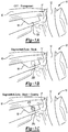
- an instrument panel 10 is shown schematically FIGS. 1A, 1B, and 1C .
- the instrument panel 10 may be used as part of a vehicle or other mobile or stationary system in certain embodiments, such as but not limited to a motor vehicle, an aircraft, or a marine vessel, any of which may include a steering input device 12 situated adjacent to a dashboard 16.
- a multi-layer polarizer lens assembly 18, which is shown in more detail in FIG. 2 selectively employs properties of reflective polarization in its operation, and thereby aids in the presentation of information to a user 11 (see FIG. 2 ), particularly under bright daylight or other high-luminance ambient lighting conditions that may otherwise adversely affect visibility of such information.
- propagating light waves generate an electric field.
- the electric field oscillates in a direction that is perpendicular/orthogonal to the light wave's direction of propagation.
- Light is unpolarized when the fluctuation of the electric field direction is random.
- light may be described as polarized when fluctuation of the electric field is highly structured, with laser beams being a common example of highly-polarized light and sunlight or diffuse overhead incandescent lighting being examples of unpolarized light.
- the polarization properties of the polarizer lens assembly 18 described herein are selectively varied to extinguish s-polarized light incident from either the front or the rear side of the polarizer lens assembly 18, as shown in FIG. 2 , to cause the polarizer lens assembly 18 to perceptibly darken from the perspective of the user 11.
- the darkened appearance in turn provides a more favorable background for projecting the polarized light as information to the user 11.
- the steering input device 12 is shown as a steering wheel, with an instrument panel 17 mounted with respect to the dashboard 16.
- the polarizer lens assembly 18 may present a substantially transparent or transparent background 100 as in FIG. 1A , such that the user 11 of FIG. 2 sees through the polarizer lens assembly 18 as a transparent or smoky pane.
- an opaque/black background 200 is generated.
- 1C shows the opaque/black background 200 with an information overlay 210, e.g., an icon, image, text, and/or other information.
- the background 200 via corresponding segmenting or sectioning of an underlying active polarizer lens 24 as described below, may be segmented or sectioned. That is, designated portions of the active polarizer lens 24 may be individually-addressable and/or otherwise selectively transitionable to the ON/polarized state forming the background for the overlay 210, while other designated portions of the active polarizer lens 24 remain in the OFF/polarized state and thus transparent.
- the present polarizer lens assembly 18 thus acts as a "smart" optical lens option by combining reflective and active polarizing technologies in a manner that reduces required display luminance and thereby produces a more optimal contrast ratio relative to the hypothetical transparent glass lens.
- the system 20 includes the display device 22, e.g., a liquid crystal display (LCD) or organic light emitting diode (OLED) screen via which information is initially presented and projected as p-polarized light (arrows LL).
- the display device 22 is mounted below the dashboard 16 and thus hidden from direct view by the user 11, with the display device 22 projecting light downward toward and onto the polarizer lens assembly 18.
- the display device 22 may be housed within the dashboard 16 and configured to project light upward toward the polarizer lens assembly 18, e.g., toward a windshield (not shown), or the polarizer lens assembly 18 may be integrated into the windshield.
- the system 20 in the illustrated configuration also includes the polarizer lens assembly 18 and a microcontroller (MC) 25.
- the microcontroller 25, shown schematically in FIG. 2 may be embodied as one or more computer devices configured to selectively control cross-polarization of the polarizer lens assembly 18 as set forth herein.
- the microcontroller 25 includes a processor (P) and tangible, non-transitory memory (M), e.g., read only memory in the form of optical, magnetic, and/or flash memory.
- the microcontroller 25 also includes application-suitable amounts of random-access memory and electrically-erasable programmable read only memory, a high-speed clock, analog-to-digital and digital-to-analog circuitry, and input/output circuitry and devices, as well as appropriate signal conditioning and buffer circuitry.
- a method 75 that may be used to control the polarization state is described below with reference to FIG. 7 .
- a sensor 21 may be positioned with respect to the system 20 and used to measure an ambient lighting level, i.e., a brightness or luminance in proximity to the polarizer lens assembly 18, and to report the measured ambient lighting level as an input signal (arrow CC I ) to the microcontroller 25.
- the sensor 21 may be one or more photocells employing a photodiode or photoresistor.
- a user input device 23 such as a mechanical knob, a button, touch-screen device, etc.
- the user input device 23 may be selectively activated in some embodiments by the user 11 to generate an activation request (arrow CC I *) as another type of input signal, e.g., requesting an ON or OFF state of the polarizer lens assembly 18.
- the microcontroller 25 may be configured to transition the active polarizer lens 24 from the OFF/unpolarized state to the ON/polarized state responsive to the activation request (arrow CC I *).
- the selection by the microcontroller 25 of a particular appearance of the polarizer lens assembly 18 may be fully automatic based on the detected ambient lighting level, fully manual based on the request of the user 11, or a combination of these two options, e.g., with manual selection being available to the user 11 to selectively override the light level-based decision of the microcontroller 25.
- the polarizer lens assembly 18 is configured to provide a reflective surface, oriented toward the user 11 as shown, onto which light-based information is projected from the display device 22.
- the polarizer lens assembly 18 is spaced a short distance apart from the display device 22, for instance about 5-10 cm apart in some configurations, and oriented at an angle ( ⁇ ) with respect to the display device 22.
- An optimum value of the angle ( ⁇ ) is based on various factors, including the reflection/transmittance properties of the particular materials used in constructing the polarizer lens assembly 18, expected ambient lighting levels, available brightness of light projected by the display device 22, etc.
- the angle ( ⁇ ) may fall in the range of about 30-60 degrees, generally, with an angle ( ⁇ ) of about 45 degrees shown in the non-limiting embodiment of FIG. 2 .
- the polarizer lens assembly 18 in its various embodiments includes an active polarizer lens (first lens) 24 and a reflective polarizer lens (second lens) 26.
- the active polarizer lens 24 may be embodied as a multi-layer structure of liquid crystal molecules sandwiched between adjacent panes of glass, plastic, or another sufficiently transparent material.
- the reflective polarizer lens 26 may include a reflective polarizer film bonded or otherwise attached an outer surface of the active polarizer lens 24.
- Two special classes of reflective polarizer materials that may be used in the construction of the reflective polarizer lens 26 commercially available as 3MTM Reflective Polarizer Mirror (RPM) and 3MTM Windshield Combiner Film (WCF), both available from THE 3M COMPANY, with headquarters located in Maplewood, MN.
- Other reflective polarizer materials having similar properties may be used to form the reflective polarizer lens 26 in other embodiments.
- orthogonal linear polarization states of light are referred to in the art as p-polarization and s-polarization.
- the electric field of p-polarized light is polarized in a direction that is parallel to the plane of incidence of the incident light beams (arrow LL) from the display device 22 shown in FIG. 2 .
- S-polarized light is perpendicular to such a plane of incidence, and thus p-polarized and s-polarized light are orthogonal to each other.
- cross-polarization results when the active polarizer layer 24 extinguishes the s-polarization component of incident light while the reflective polarizer lens 26 reflects the p-polarization component.
- the polarizer lens assembly 18 is configured to selectively extinguish s-polarized light while the reflective polarizer lens 26, oriented toward the display device 22, reflects incident p-polarized light from the display device 22 toward the user 11.
- the ultimate effect is that a small fraction of incident light, e.g., 13.5% or less in some embodiments, will pass through the polarizer lens assembly 18.
- the reflective polarizer lens 26 also reflects p-polarized light away from the back side of the polarized light assembly 18 due to the reciprocity nature of the reflective polarizer lens 26.
- the active polarizer lens 24 When transitioned to the non-activated/OFF state as shown in FIG. 1A , the active polarizer lens 24 transmits light and, as a result, appears as transparent to the user 11. Used in a vehicle, for instance, this state may be a default state when the vehicle is turned off and/or when the system 20 is operated under low ambient lighting conditions.
- the active polarizer lens 24 blocks light that is incident parallel to the transmission axis of the reflective polarizer lens 26, thereby providing the appearance of an opaque/black background as best shown in FIG. 1B , onto which information from the display device 22 may be projected as shown in FIG. 1C .
- the microcontroller 25 may be placed in communication with the polarizer lens assembly 18, and in particular with the active polarizer lens 24, via a communications interface 251 such as a hardwired connection and/or a flex circuit. In some embodiments, the microcontroller 25 may be used to simultaneously control operation of the display device 22, or a separate control device may be used for this purpose.
- the polarizer lens assembly 18 may be voltage-driven, e.g., via a polyphase drive waveform having a predetermined frequency and amplitude, with such a drive frequency generally being at least 60 Hz.
- a polyphase/AC waveform may be used to avoid charge migration in the liquid crystal molecule interior of the active polarizer lens 24, as will be appreciated by those of ordinary skill in the art.
- the microcontroller 25 may command one of two different polarization rates, i.e., OFF/unpolarized or ON/polarized.
- the ON state corresponds to a substantially opaque or black appearance.
- the microcontroller 25 can select an opacity level from a range that varies from partially opaque to substantially or fully opaque.
- the term "partially opaque” may refer to light transmittance rates of about 60-70% or more, while “substantially opaque” may correspond light transmittance rates of less than about 30-40%.
- black may refer to a light transmittance rate of about 10-20% or less.
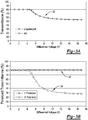
- unpolarized light transmission of the active polarizer lens 24 may range from about 80% down to about 54% as a function of drive voltage, shown as a differential voltage across opposing surfaces of the active polarizer lens 24.
- FIG. 3B shows via trace 32 that p-polarized light transmission does not change as a function of the drive voltage, but rather remains constant at about 80%.
- the transmission rate (trace 34) of cross-polarized (s-polarized) light changes from about 80% down to about 28% as a function of the drive voltage. This enables cross-polarization properties to be leveraged to achieve the visual enhancements described herein.
- T X_OFF the cross-polarization transmission with zero drive
- T X_ON the cross-polarization transmission with maximum drive
- T X_OFF T
- the active polarizer lens 24 may transmit about 80% of p-polarized light in its OFF/non-polarized state.
- the transmission of s-polarized light drops from 80% in the OFF state to less than 30.4% in the ON/polarized state.
- the ON/polarized state of the active polarizer lens 24 may realize transmission rates that are much lower than 30%, e.g., as low as about 10-15%, but at the expense of the OFF transmission, which would also drop accordingly.
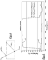
- FIG. 5 shows an embodiment of reflection spectra for the reflective polarizer layer 26, e.g., constructed of materials similar to the above-noted RPM or other sufficiently reflective material that is optically flat with little reflected image distortion.
- RPM is just one type of reflective material usable in the construction of the reflective polarizer layer 26
- the indicated reflection spectra of FIG. 5 is non-limiting and intended as instructive of the present teachings.
- the reflective polarizer layer 26 has a p-polarized light reflection rate (trace 44/reflected p-polarization) of approximately 99%, and an s-polarized light reflection rate (trace 42/reflected s-polarization) of about 11%. Since incident light (arrows LL of FIG.
- transmission spectra are provided for a particular type of reflective polarizer material, in this instance the above-noted RPM, in comparison to non-reflecting materials, i.e., absorbing materials.
- Traces 60, 62, 64, and 66 represent transmission percentages at corresponding wavelengths of light.
- Traces 60 and 62 represent p-polarized light from the display device 22 that is blocked (i.e., reflected) and transmitted, respectively. More specifically, trace 62 represents the amount of polarized light that is transmitted when the polarized electric field axis is aligned to the transmission axis of the reflective polarizer lens 26 of FIG. 2 .
- the amount of light that is transmitted represented by trace 60, is nearly 0% up to about 850nm.
- Traces 64 and 66 represent capabilities of conventional absorbing/non-reflecting or dichroic materials by way of comparison, with trace 66 representing polarized light that is aligned with the transmission axis and trace 64 representing the amount of transmitted polarized light when the polarized light is rotated 90 degrees from the transmission axis of the absorbing polarizer material.
- trace 66 representing polarized light that is aligned with the transmission axis
- trace 64 representing the amount of transmitted polarized light when the polarized light is rotated 90 degrees from the transmission axis of the absorbing polarizer material.
- certain crystalline materials absorb more light in one incident plane relative to another incident plane, such that light transmitted through the absorbing material is progressively polarized.
- the present approach thus may be characterized by the use of the reflective polarizer lens 26 in lieu of such absorbing materials.
- T Driven_AP is the transmission rate of s-polarized light when the active polarizer ("AP") lens 24 in the driven state
- L S is the percentage of light in the s-polarized orientation
- T S is the transmission rate of s-polarized light
- AP S_Driven is the transmission rate of s-polarized light when the active polarizer lens 24 is in the driven state.
- the active polarizer lens 24 When the display device 22 of FIG. 2 is off and the active polarizer lens 24 is OFF/unpolarized, the active polarizer lens 24 will transmit substantially all of, e.g., about 87% of, incident p-polarized and s-polarized light components. For the representative material whose performance is depicted in FIG. 6 , 50% of the light is not transmitted, while the remaining 50% is transmitted at a 90% transmission rate.
- T Undriven_AP is the transmission rate of the active polarizer lens 24 in the undriven state
- AP S_Undriven is the transmission rate of the s-polarized light when the active polarizer lens 24 is in the undriven state.
- the reflective polarizer lens 26 is reflecting essentially 100% of incident p-polarized light from its back side in a non-transmissive orientation, 38% of the light, per equation [8] below, will be recycled and reflected toward the dashboard 16 of FIGS. 1A-C , thus mitigating some of the effects of the 39% transmission rate.
- the p-polarized light reflection rate does not change as the active polarizer lens 24 is actively driven, and therefore the amount of reflected light will remain constant at 38%.
- R Backside L P ⁇ R P ⁇ AP P 2
- R Backside is the reflection rate of the active polarizer lens 24
- L P is the percentage of light in the p-polarized orientation
- R P is the reflection rate of the material for p-polarized light
- AP P is the active polarizer transmission rate for p-polarized light.
- the parameter AP P is squared in equation [8], since the reflected p-polarized light must pass twice through the active polarizer lens 24.
- a beneficial aspect of the active polarizer lens 24 is that it can be segmented if desired, thereby allowing activation of predefined "zones".
- designated zones of the active polarizer lens 24 could be activated to become opaque, thereby creating an application-tailored appearance. For example, if a small icon is to be displayed, a corresponding portion of the surface area of the active polarizer lens 24 may be transitioned to the ON state and thus rendered substantially opaque, with the remainder of the active polarizer lens 24 remaining in the OFF state, and thus largely transparent.
- Another variation of the active polarizer configuration is to utilize "weaker" reflective polarizer material, e.g., the WCF material noted above or another material having a reflectivity of about 30% to p-polarized light at a 55° angle of incidence.
- the weaker material should transmit about 44% of p-polarized light when the active polarizer lens 24 is in the ON/driven state. In the OFF/non-driven state, a transmission rate of about 70% may be desirable, and therefore WCF and other weaker materials may appear to the user 11 as clearer relative to using stronger materials such as the aforementioned RPM. Therefore, actual materials of construction may be selected to provide the desired appearance.
- a variation in the construction of the polarizer lens assembly 18 may include the reflective polarizer lens 26 constructed of material that reflects about 99% of the incident p-polarized light from the display device 22. Back side reflectance may be increased to 50%, since substantially all of the p-polarized light is reflected. Light is recycled to mitigate some of the loss in transparency.
- a light reflectance rate of about 30% remains.
- a method 75 for displaying information to the user 11 may include, at block B100, projecting the information onto the polarizer lens assembly 18 of FIG. 2 as p-polarized light using the display device 22.
- the method 75 may include detecting ambient light via the sensor 21 of FIG. 2 , and then transmitting the input signal (CC I ) to the microcontroller 25.
- the input signal (CC I ) in this instance is indicative of the ambient lighting level. The method 75 then proceeds to block B104.
- Block B104 may entail comparing the measured ambient light level from block B102 to one or more calibrated lighting thresholds. The method 75 proceeds to block B105 if the detected ambient light level from block B102 is less than the threshold(s) from block B104, and to block B106 in the alternative when the ambient light level exceeds one or more of the threshold(s).
- Block B105 of method 75 may include receiving the activation request (CC I *) as another input signal from the user input device 23 of FIG. 2 , via the microcontroller 25, and then determining whether the activation request (CC I *) is indicative of a desire of the user 11 to leave the polarizer lens assembly 18 in an OFF state. Such a result may correspond to a manual override of the above-noted light-based activation. The method 75 returns to block B100 when such an override is detected.
- the microcontroller 25 transmits a drive signal to the active polarizer lens 24 of FIG. 2 for transitioning the active polarizer lens 24 from the OFF/unpolarized state and a substantially transparent appearance to the ON/polarized state and a substantially opaque/black appearance.
- the ON/polarized state may include a plurality of ON/polarized states, each corresponding to a particular band of ambient lighting, with each ON/polarized state corresponding to a respective one of the ambient lighting level bands.
- the above method 75 or variations thereof may be implemented as a non-transitory computer-readable medium, e.g., the memory (M) shown in FIG. 2 or a separate medium such as a memory chip, with computer-readable instructions stored therein for displaying information to the user 11 of the instrument panel.
- a non-transitory computer-readable medium e.g., the memory (M) shown in FIG. 2 or a separate medium such as a memory chip, with computer-readable instructions stored therein for displaying information to the user 11 of the instrument panel.
- the instructions when executed by the processor (P) of the microcontroller 25, causes the microcontroller 25 to perform the above-noted process steps, e.g., to command the display device 22 to project information onto the polarizer lens assembly 18 as p-polarized light, receive the input signal (CC I ) and/or activation signal CC I * from the ambient light sensor(s) 21 and/or the user input device 23, and transmit a drive signal to the active polarizer lens 24 in response to the input signal/user activation request (CC I , CC I *) to transition the active polarizer lens 24 from the OFF/unpolarized state and a substantially transparent appearance to the ON/polarized state and a substantially opaque appearance.
- the various other logic blocks of FIG. 7 may be similarly implemented.
Abstract
A system displays information to a user and includes a display device, a polarizer lens assembly, and a microcontroller. The display device projects the information as p-polarized light. The polarizer lens assembly is oriented at an angle with respect to the display device, and includes an active polarizer lens and a reflective polarizer lens. The active polarizer lens has an OFF/unpolarized and one or more ON/polarized states. The polarizer lens assembly has a substantially transparent appearance in the OFF/polarized state(s) and a substantially opaque appearance in the ON/polarized state. The reflective polarizer lens is adjacent to the active polarizer lens between the display device and the active polarizer lens, and reflects the p-polarized light. The microcontroller, in response to an input signal, transmits a drive signal to the active polarizer lens to transition the active polarizer lens from the OFF/unpolarized state to the ON/polarized state.
Description
- The present disclosure generally relates to systems and methods for increasing the contrast ratio of light-based information reflected onto an image plane, such as within an electronic instrument panel of a vehicle.
- Instrument panels may include clusters of gauges, with each gauge presenting operationally relevant information to a system user. An instrument panel may be positioned within the user's field of view. The individual gauges are configured to convey particular pieces of information, such as a remaining fuel level, current speed and heading, and ambient, external, and/or component-level temperature, etc.
- Early instrument panels employed gauge clusters that operated primarily as analog devices. In a motor vehicle context, for instance, analog speedometers and fuel gauges may have an indicator, such as a needle or a pointer, that is physically moved by a corresponding input between defined lower and upper range limits. In contrast to analog gauges, modern digital gauges may include transducers or other sensors which output electrical signals to a microprocessor. The electrical signals may be proportional to the measured value, e.g., a proportional voltage signal. In response to such signals, the microprocessor automatically adjusts a corresponding digital readout for display to the user, e.g., as a graphical icon, an image, and/or text.
- Systems and methods are disclosed herein for enhancing the visibility of light-based information that is reflected onto an image plane of an electronic instrument panel, e.g., as a digital gauge cluster and/or another information display. Enhancement may be attained by the resulting increase in contrast ratio, particularly when operating the instrument panel under relatively bright ambient lighting conditions. The system according to an embodiment includes a display device which projects the information, as p-polarized light, toward a polarizer lens assembly configured as described herein. In general, the polarizer lens assembly utilizes active polarizer technology, e.g., liquid crystal molecules suspended with a guest dye, such that the liquid crystals act as a host and the dye acts as the guest that couples itself to the host. The liquid crystal molecules selectively align in response to an applied drive voltage, to selectively transition the polarizer lens assembly from a transparent/semi-transparent appearance in an OFF/nonpolarized state to a substantially-opaque or black appearance in an ON/polarized state, as perceived by the above-noted user. A "user" as used herein refers to an operator of a system that includes the instrument panel, and may therefore variously include a driver of a motor vehicle, a pilot of an aircraft, an operator of a marine vessel or watercraft, an operator of a stationary or mobile piece of equipment, etc.
- The transparent-to-opaque transition noted above may be selectively triggered under high luminance ambient lighting conditions, such as when the instrument panel is exposed to direct sunlight. Selective activation in this manner may help improve contrast ratios and enhance overall visibility of the displayed information.
- In an embodiment, the polarizer lens assembly includes adjacent first and second layers/lenses. The first lens may be embodied as a liquid crystal material-based active polarizer lens. The second lens, which is situated closer to the user than is the first lens, is embodied as a reflective polarizer layer, e.g., a thin film, that may be bonded or otherwise securely attached to an outer surface of the first lens.
- The first lens may be optionally segmented or sectioned, i.e., having one or more portions with a variable polarization and one or more portions whose polarization cannot be varied, or alternatively having independently-drivable portions. Such an embodiment may enable certain segments of the first lens to be transitioned to the ON/polarized state while other segments remain in the OFF/unpolarized state.
- A microcontroller may be used as part of the system and an accompanying control strategy. The microcontroller may selectively control the ON/OFF polarized state of the active polarizer lens (first lens), e.g., in response to a sensor-detected ambient lighting level or, in other embodiments, via a user-selected activation request. The microcontroller is in communication with the optional sensor, the active polarizer lens, and the above-noted display device, the latter of which may be variously embodied a liquid crystal display (LCD), an organic light-emitting diode (OLED) display, or another suitable device configured to project information as p-polarized light toward and onto the polarizer lens assembly.
- In response to an input signal indicative of a threshold low level of ambient light, and/or in response to a user's selection via a touch input or activation of a corresponding mechanical input device, the microcontroller transmits a drive signal to the active polarizer lens, e.g., as a proportional or differential voltage signal. The drive signal in turn adjusts light transmittance properties of the active polarizer lens as set forth in detail herein. Therefore, when the polarizer lens assembly is in an OFF/unpolarized state, the appearance of the polarizer lens assembly to the user is that of a transparent pane. However, when the polarizer lens assembly is transitioned to the ON state by the aforementioned drive signal, the polarizer lens assembly perceptibly darkens to form a dark background that is more conducive to display of the information.
- The extent of the darkening effect may be calibrated such that, in a simplified embodiment, a single level of opacity is achieved by transitioning to the ON state. That is, the polarizer lens assembly is either transparent or it is substantially opaque/black. In another embodiment, the opacity level may be varied anywhere between partially opaque and black, e.g., in proportion to the detected ambient lighting level and/or the user's activation input. In either embodiment, the microcontroller is able to selectively darken the background of the displayed information. In this manner, the polarizer lens assembly improves visibility under high luminance ambient lighting conditions that would otherwise make it difficult for the user to easily discern the projected information.
- In a particular embodiment, a system for displaying information to a user includes a display device configured to project the information as p-polarized light, a polarizer lens assembly having an active polarizer lens and a reflective polarizer lens, and a microcontroller. The active polarizer lens has an OFF/unpolarized state and an ON/polarized state. The polarizer lens assembly, which acts as an image plane, has a substantially transparent appearance when the active polarizer lens is in the OFF/unpolarized state and a substantially opaque appearance when the active polarizer lens in the ON/polarized state. The reflective polarizer lens is positioned adjacent to the active polarizer lens between the display device and the active polarizer lens, and is configured to reflect the p-polarized light. The microcontroller is configured to communicate with the active polarizer lens. In response to an input signal, the microcontroller transmits a drive signal to the active polarizer lens, e.g., as a proportional or differential voltage signal, which transitions the active polarizer lens from the OFF/unpolarized state to the ON/polarized state.
- In another embodiment, a non-transitory computer-readable medium has computer-readable instructions stored therein for displaying information to a user of an instrument panel. The instrument panel has a display device and a polarizer lens assembly. Execution of the computer-readable instructions by a processor of a microcontroller causes the microcontroller to command the display device to project information onto the polarizer lens assembly as p-polarized light, with the polarizer lens assembly oriented at a predetermined angle with respect to the display device. The polarizer lens assembly also includes an active polarizer lens having an OFF/unpolarized state and an ON/polarized state, and a reflective polarizer lens positioned adjacent to the active polarizer lens between the display device and the active polarizer lens. The reflective polarizer lens reflects substantially all of the p-polarized light incident on the reflective polarizer lens, regardless of the ON/OFF state of the active polarizer lens.
- Execution of the instructions causes the microcontroller to receive an input signal from an ambient light sensor and/or a user input device, and to transmit a drive signal to the active polarizer lens in response to the input signal. The drive signal transitions the active polarizer lens from the OFF/unpolarized state and a substantially transparent appearance to the ON/polarized state and a substantially opaque appearance.
- A system according to another embodiment may be used aboard a vehicle having a steering input device and a dashboard. The system may include an instrument panel and the microprocessor, with the instrument panel positioned adjacent to the steering input device and dashboard. The instrument panel includes the above-noted display device and polarizer lens assembly. The display device in this embodiment projects digital information onto the polarizer lens assembly as p-polarized light, with the light possibly forming a digital gauge/gauge cluster of the instrument panel. The polarizer lens assembly, which is oriented at a predetermined angle with respect to the display device, includes an active polarizer lens having an OFF/unpolarized state and an ON/polarized state, and also includes a reflective polarizer lens.
- The polarizer lens assembly has a substantially transparent appearance when the active polarizer lens is in the OFF/unpolarized state and a substantially opaque appearance when the active polarizer lens in the ON/polarized state. The reflective polarizer lens is positioned adjacent to the active polarizer lens between the display device and the active polarizer lens, and reflects substantially all of the p-polarized light falling incident on the reflective polarizer lens. A microcontroller communicates with the active polarizer lens. Responsive to an input signal, the microcontroller transmits a drive signal to the active polarizer lens to transition the active polarizer lens from the OFF/unpolarized state to the ON/polarized state.
- The above features and advantages and other features and advantages of the present teachings are readily apparent from the following detailed description of the best modes for carrying out the teachings when taken in connection with the accompanying drawings.
-
-
FIGS. 1A, 1B, and 1C are schematic perspective view illustrations of an instrument panel having a polarizer lens assembly constructed in accordance with one or more of the embodiments disclosed herein. -
FIG. 2 is a schematic illustration of a system for enhancing the visibility of projected information, with the system including a display device, a polarizer lens assembly, and a microcontroller in a possible embodiment. -
FIGS. 3A and 3B are plots of light transmission for unpolarized and polarized variations of an active polarizer lens as shown inFIG. 2 , respectively, with differential voltage depicted on the horizontal axis and light transmittance percentage depicted on the vertical axis. -
FIG. 4 is a graphical depiction of a first-order reflection model that may be used in a disclosed embodiment. -
FIG. 5 is a plot of polarized light reflectivity for a material usable as part of the polarizer lens assembly, with wavelength depicted on the horizontal axis and reflection percentage depicted on the vertical axis. -
FIG. 6 is a plot of polarized light transmission for an absorptive-type reference material and a reflective polarizer material that, in a possible embodiment, may be used as part of the polarizer lens assembly shown inFIG. 2 , with the reference material shown for the purpose of comparison with wavelength depicted on the horizontal axis and light transmission percentage depicted on the vertical axis. -
FIG. 7 is a flow chart showing an embodiment of a method for increasing the contrast ratio of information displayed on the polarizer lens assembly described herein. - The present disclosure may have various modifications and alternative forms, and some representative embodiments are shown by way of example in the drawings and will be described in detail herein. Novel aspects of this disclosure are not limited to the particular forms illustrated in the above-enumerated drawings. Rather, the disclosure is to cover modifications, equivalents, and combinations falling within the scope of the disclosure as encompassed by the appended claims.
- Those having ordinary skill in the art will recognize that terms such as "above," "below," "front", "back", "upward," "downward," "top," "bottom," etc., may be used descriptively herein without representing limitations on the scope of the disclosure, as defined by the appended claims. Furthermore, the present teachings may be described in terms of functional and/or logical block components and/or various processing steps. Such block components may be comprised of various hardware, software, and/or firmware components configured to perform the specified functions.
- Referring to the drawings, wherein like numerals indicate like parts throughout the several views, an
instrument panel 10 is shown schematicallyFIGS. 1A, 1B, and 1C . Theinstrument panel 10 may be used as part of a vehicle or other mobile or stationary system in certain embodiments, such as but not limited to a motor vehicle, an aircraft, or a marine vessel, any of which may include asteering input device 12 situated adjacent to adashboard 16. A multi-layerpolarizer lens assembly 18, which is shown in more detail inFIG. 2 , selectively employs properties of reflective polarization in its operation, and thereby aids in the presentation of information to a user 11 (seeFIG. 2 ), particularly under bright daylight or other high-luminance ambient lighting conditions that may otherwise adversely affect visibility of such information. - In general, propagating light waves generate an electric field. The electric field oscillates in a direction that is perpendicular/orthogonal to the light wave's direction of propagation. Light is unpolarized when the fluctuation of the electric field direction is random. Conversely, light may be described as polarized when fluctuation of the electric field is highly structured, with laser beams being a common example of highly-polarized light and sunlight or diffuse overhead incandescent lighting being examples of unpolarized light. The polarization properties of the
polarizer lens assembly 18 described herein are selectively varied to extinguish s-polarized light incident from either the front or the rear side of thepolarizer lens assembly 18, as shown inFIG. 2 , to cause thepolarizer lens assembly 18 to perceptibly darken from the perspective of theuser 11. The darkened appearance in turn provides a more favorable background for projecting the polarized light as information to theuser 11. - In the illustrated embodiment of
FIGS. 1A-C , thesteering input device 12 is shown as a steering wheel, with aninstrument panel 17 mounted with respect to thedashboard 16. Such a configuration may be useful in a motor vehicle, for instance, or in an aircraft, boat, or other watercraft. In its OFF state ofFIG. 1A , thepolarizer lens assembly 18 may present a substantially transparent ortransparent background 100 as inFIG. 1A , such that theuser 11 ofFIG. 2 sees through thepolarizer lens assembly 18 as a transparent or smoky pane. In the ON state depicted inFIG. 1B , an opaque/black background 200 is generated.FIG. 1C shows the opaque/black background 200 with aninformation overlay 210, e.g., an icon, image, text, and/or other information. Thebackground 200, via corresponding segmenting or sectioning of an underlyingactive polarizer lens 24 as described below, may be segmented or sectioned. That is, designated portions of theactive polarizer lens 24 may be individually-addressable and/or otherwise selectively transitionable to the ON/polarized state forming the background for theoverlay 210, while other designated portions of theactive polarizer lens 24 remain in the OFF/polarized state and thus transparent. - As a point of reference, one may consider the effects of a fully-transparent pane of glass as a reflective surface in lieu of the disclosed
polarizer lens assembly 18. Such glass would present a transparent "floating display" appearance. However, in order to obtain sufficient luminance of a virtual image or other displayed information, e.g., of greater than 400 candela per square meter (cd/m2), a display luminance of approximately 5,000 cd/m2 would be required, assuming that front and rear surfaces of such a hypothetical transparent glass pane each reflect at a 4% (0.04) reflection rate, i.e.:
- The amount of required display luminance approximately doubles at an angle of incidence of 45 degrees relative to the obtainable luminance at 0 degrees. The corresponding display luminance may require significant thermal management countermeasures and associated costs. The present
polarizer lens assembly 18 thus acts as a "smart" optical lens option by combining reflective and active polarizing technologies in a manner that reduces required display luminance and thereby produces a more optimal contrast ratio relative to the hypothetical transparent glass lens. - The
system 20 for enhancing visibility of displayed information is shown in further schematic detail inFIG. 2 . In a possible embodiment, thesystem 20 includes thedisplay device 22, e.g., a liquid crystal display (LCD) or organic light emitting diode (OLED) screen via which information is initially presented and projected as p-polarized light (arrows LL). In the non-limiting embodiment ofFIGS. 1A-C , for instance, thedisplay device 22 is mounted below thedashboard 16 and thus hidden from direct view by theuser 11, with thedisplay device 22 projecting light downward toward and onto thepolarizer lens assembly 18. Alternatively, thedisplay device 22 may be housed within thedashboard 16 and configured to project light upward toward thepolarizer lens assembly 18, e.g., toward a windshield (not shown), or thepolarizer lens assembly 18 may be integrated into the windshield. - The
system 20 in the illustrated configuration also includes thepolarizer lens assembly 18 and a microcontroller (MC) 25. Themicrocontroller 25, shown schematically inFIG. 2 , may be embodied as one or more computer devices configured to selectively control cross-polarization of thepolarizer lens assembly 18 as set forth herein. Themicrocontroller 25 includes a processor (P) and tangible, non-transitory memory (M), e.g., read only memory in the form of optical, magnetic, and/or flash memory. Themicrocontroller 25 also includes application-suitable amounts of random-access memory and electrically-erasable programmable read only memory, a high-speed clock, analog-to-digital and digital-to-analog circuitry, and input/output circuitry and devices, as well as appropriate signal conditioning and buffer circuitry. - Execution of such logic by the processor (P) ultimately causes the
microcontroller 25 to control the ON/OFF state of thepolarizer lens assembly 18 using control signals (arrow CCO) to achieve a desired lighting effect. Amethod 75 that may be used to control the polarization state is described below with reference toFIG. 7 . Asensor 21 may be positioned with respect to thesystem 20 and used to measure an ambient lighting level, i.e., a brightness or luminance in proximity to thepolarizer lens assembly 18, and to report the measured ambient lighting level as an input signal (arrow CCI) to themicrocontroller 25. In such an embodiment, thesensor 21 may be one or more photocells employing a photodiode or photoresistor. - In another embodiment, which may be used alone or in conjunction with the
sensor 21, auser input device 23 such as a mechanical knob, a button, touch-screen device, etc., may be connected by wire or wirelessly to themicrocontroller 25. Theuser input device 23 may be selectively activated in some embodiments by theuser 11 to generate an activation request (arrow CCI*) as another type of input signal, e.g., requesting an ON or OFF state of thepolarizer lens assembly 18. For instance, themicrocontroller 25 may be configured to transition theactive polarizer lens 24 from the OFF/unpolarized state to the ON/polarized state responsive to the activation request (arrow CCI*). Therefore, the selection by themicrocontroller 25 of a particular appearance of thepolarizer lens assembly 18 may be fully automatic based on the detected ambient lighting level, fully manual based on the request of theuser 11, or a combination of these two options, e.g., with manual selection being available to theuser 11 to selectively override the light level-based decision of themicrocontroller 25. - Still referring to
FIG. 2 , thepolarizer lens assembly 18 is configured to provide a reflective surface, oriented toward theuser 11 as shown, onto which light-based information is projected from thedisplay device 22. Thepolarizer lens assembly 18 is spaced a short distance apart from thedisplay device 22, for instance about 5-10 cm apart in some configurations, and oriented at an angle (θ) with respect to thedisplay device 22. An optimum value of the angle (θ) is based on various factors, including the reflection/transmittance properties of the particular materials used in constructing thepolarizer lens assembly 18, expected ambient lighting levels, available brightness of light projected by thedisplay device 22, etc. The angle (θ) may fall in the range of about 30-60 degrees, generally, with an angle (θ) of about 45 degrees shown in the non-limiting embodiment ofFIG. 2 . - The
polarizer lens assembly 18 in its various embodiments includes an active polarizer lens (first lens) 24 and a reflective polarizer lens (second lens) 26. Theactive polarizer lens 24 may be embodied as a multi-layer structure of liquid crystal molecules sandwiched between adjacent panes of glass, plastic, or another sufficiently transparent material. Thereflective polarizer lens 26 may include a reflective polarizer film bonded or otherwise attached an outer surface of theactive polarizer lens 24. Two special classes of reflective polarizer materials that may be used in the construction of thereflective polarizer lens 26 commercially available as 3M™ Reflective Polarizer Mirror (RPM) and 3M™ Windshield Combiner Film (WCF), both available from THE 3M COMPANY, with headquarters located in Maplewood, MN. Other reflective polarizer materials having similar properties may be used to form thereflective polarizer lens 26 in other embodiments. - With regard to the properties of transmission and reflection, orthogonal linear polarization states of light are referred to in the art as p-polarization and s-polarization. The electric field of p-polarized light is polarized in a direction that is parallel to the plane of incidence of the incident light beams (arrow LL) from the
display device 22 shown inFIG. 2 . S-polarized light is perpendicular to such a plane of incidence, and thus p-polarized and s-polarized light are orthogonal to each other. Thus, cross-polarization results when theactive polarizer layer 24 extinguishes the s-polarization component of incident light while thereflective polarizer lens 26 reflects the p-polarization component. In turn, this causes thepolarizer lens assembly 18 to take on a darker appearance, since neither the s-polarization light component nor the p-polarization light component can shine through thepolarizer lens assembly 18. Thepolarizer lens assembly 18 is configured to selectively extinguish s-polarized light while thereflective polarizer lens 26, oriented toward thedisplay device 22, reflects incident p-polarized light from thedisplay device 22 toward theuser 11. The ultimate effect is that a small fraction of incident light, e.g., 13.5% or less in some embodiments, will pass through thepolarizer lens assembly 18. Thereflective polarizer lens 26 also reflects p-polarized light away from the back side of the polarizedlight assembly 18 due to the reciprocity nature of thereflective polarizer lens 26. - When transitioned to the non-activated/OFF state as shown in
FIG. 1A , theactive polarizer lens 24 transmits light and, as a result, appears as transparent to theuser 11. Used in a vehicle, for instance, this state may be a default state when the vehicle is turned off and/or when thesystem 20 is operated under low ambient lighting conditions. When activated by themicrocontroller 25, theactive polarizer lens 24 blocks light that is incident parallel to the transmission axis of thereflective polarizer lens 26, thereby providing the appearance of an opaque/black background as best shown inFIG. 1B , onto which information from thedisplay device 22 may be projected as shown inFIG. 1C . - The
microcontroller 25 may be placed in communication with thepolarizer lens assembly 18, and in particular with theactive polarizer lens 24, via acommunications interface 251 such as a hardwired connection and/or a flex circuit. In some embodiments, themicrocontroller 25 may be used to simultaneously control operation of thedisplay device 22, or a separate control device may be used for this purpose. Thepolarizer lens assembly 18 may be voltage-driven, e.g., via a polyphase drive waveform having a predetermined frequency and amplitude, with such a drive frequency generally being at least 60 Hz. A polyphase/AC waveform may be used to avoid charge migration in the liquid crystal molecule interior of theactive polarizer lens 24, as will be appreciated by those of ordinary skill in the art. - In a simplified embodiment, the
microcontroller 25 may command one of two different polarization rates, i.e., OFF/unpolarized or ON/polarized. The ON state corresponds to a substantially opaque or black appearance. Alternatively, themicrocontroller 25 can select an opacity level from a range that varies from partially opaque to substantially or fully opaque. In an embodiment, the term "partially opaque" may refer to light transmittance rates of about 60-70% or more, while "substantially opaque" may correspond light transmittance rates of less than about 30-40%. Likewise, "black" may refer to a light transmittance rate of about 10-20% or less. These or other values may be established by controlling the magnitude of the drive voltage. - The various embodiments may be informed using the
sensor 21 ofFIG. 2 , with themicrocontroller 25 selecting the ON/OFF state and the opacity level based on the level of the detected light. In other words, themicrocontroller 25 may determine in certain lighting conditions that the OFF state will result in sufficient reflectance of the information from thedisplay device 22. Conversely, themicrocontroller 25 may transition to the ON state under brighter/daylight lighting conditions. A lookup table may be optionally populated with different drive voltages and corresponding light ranges, for instance, with themicrocontroller 25 selecting and applying a particular drive voltage that corresponds to the detect light level. These and other possible implementations may be envisioned in view of the present disclosure. - As shown in
trace 30 ofFIG. 3A , unpolarized light transmission of theactive polarizer lens 24 may range from about 80% down to about 54% as a function of drive voltage, shown as a differential voltage across opposing surfaces of theactive polarizer lens 24. However, this may be contrasted withFIG. 3B , which shows viatrace 32 that p-polarized light transmission does not change as a function of the drive voltage, but rather remains constant at about 80%. On the other hand, the transmission rate (trace 34) of cross-polarized (s-polarized) light changes from about 80% down to about 28% as a function of the drive voltage. This enables cross-polarization properties to be leveraged to achieve the visual enhancements described herein. - More accurate light transmission rate estimates for the
active polarizer lens 24 can be obtained by considering glass-to-air reflection rates in the analysis. Due to an index of refraction interface mismatch, the following Fresnel equation [1] may be used to estimate a reflection rate (R) at each glass-to-air interface. Using 1 and 1.52 as the indexes of refraction (η) for air and glass, respectively:
- Using a first-order reflection model as shown in
FIG. 4 , output luminance (LO) may be calculated by multiplying the input luminance (LI) by the factors shown below in equation [2], where T is the transmission of the active polarizer lens 24:

- An important observation associated with active polarizer technology is that parallel-polarized transmission, T ||, does not change as a function of drive level, wheras the cross-polarization transmission, TX , changes dramatically as a function of drive level. At the drive extremes, cross-polarization transmissions may be defined as set forth in equations [4] and [5] below, where TX_OFF is the cross-polarization transmission with zero drive, and TX_ON is the cross-polarization transmission with maximum drive. Also, TX_OFF = T || = constant, because no preferential polarization axis is present when dye molecules suspended within the liquid crystal material of the
active polarizer lens 24 are vertically aligned. Therefore, equation [3] noted above may be used to determine the effective active polarizer transmission rates as follows:

- Thus, in a possible implementation, the
active polarizer lens 24 may transmit about 80% of p-polarized light in its OFF/non-polarized state. However, when voltage is applied to theactive polarizer lens 24, the transmission of s-polarized light drops from 80% in the OFF state to less than 30.4% in the ON/polarized state. For certain materials, therefore, particularly those having higher dye concentrations, the ON/polarized state of theactive polarizer lens 24 may realize transmission rates that are much lower than 30%, e.g., as low as about 10-15%, but at the expense of the OFF transmission, which would also drop accordingly. -
FIG. 5 shows an embodiment of reflection spectra for thereflective polarizer layer 26, e.g., constructed of materials similar to the above-noted RPM or other sufficiently reflective material that is optically flat with little reflected image distortion. As RPM is just one type of reflective material usable in the construction of thereflective polarizer layer 26, the indicated reflection spectra ofFIG. 5 is non-limiting and intended as instructive of the present teachings. In the illustrated embodiment, thereflective polarizer layer 26 has a p-polarized light reflection rate (trace 44/reflected p-polarization) of approximately 99%, and an s-polarized light reflection rate (trace 42/reflected s-polarization) of about 11%. Since incident light (arrows LL ofFIG. 2 ) from thedisplay device 22 is p-polarized, as noted above, approximately 100% of such incident light will be reflected. This greatly reduces the amount of display luminance that is needed to obtain luminance of 400 cd/m2 in a reflected virtual image or other projected information. - With respect to
FIG. 6 , transmission spectra are provided for a particular type of reflective polarizer material, in this instance the above-noted RPM, in comparison to non-reflecting materials, i.e., absorbing materials.Traces Traces display device 22 that is blocked (i.e., reflected) and transmitted, respectively. More specifically,trace 62 represents the amount of polarized light that is transmitted when the polarized electric field axis is aligned to the transmission axis of thereflective polarizer lens 26 ofFIG. 2 . When the same polarized light is rotated 90 degrees to the transmission axis of thereflective polarize lens 26 material, the amount of light that is transmitted, represented bytrace 60, is nearly 0% up to about 850nm. -
Traces trace 66 representing polarized light that is aligned with the transmission axis and trace 64 representing the amount of transmitted polarized light when the polarized light is rotated 90 degrees from the transmission axis of the absorbing polarizer material. As will be appreciated, certain crystalline materials absorb more light in one incident plane relative to another incident plane, such that light transmitted through the absorbing material is progressively polarized. The present approach thus may be characterized by the use of thereflective polarizer lens 26 in lieu of such absorbing materials. - Using a 90% transmissive rate for s-polarized light through the
reflective polarizer lens 26, if theactive polarizer lens 24 is fully-driven, the amount of light transmission from the back side of theactive polarizer lens 24 may be estimated at 13.5%, i.e., thepolarizer lens assembly 18 will appear dark to theuser 11. The following equation [6] does not consider the p-polarized light component because, inFIG. 6 , 0% of the p-polarized light is transmitted:

lens 24 in the driven state, LS is the percentage of light in the s-polarized orientation, TS is the transmission rate of s-polarized light, and APS_Driven is the transmission rate of s-polarized light when theactive polarizer lens 24 is in the driven state. - When the
display device 22 ofFIG. 2 is off and theactive polarizer lens 24 is OFF/unpolarized, theactive polarizer lens 24 will transmit substantially all of, e.g., about 87% of, incident p-polarized and s-polarized light components. For the representative material whose performance is depicted inFIG. 6 , 50% of the light is not transmitted, while the remaining 50% is transmitted at a 90% transmission rate. Therefore, the total transmission of theactive polarizer lens 24 will be about 39%, i.e.:

active polarizer lens 24 in the undriven state and APS_Undriven is the transmission rate of the s-polarized light when theactive polarizer lens 24 is in the undriven state. - Furthermore, since the
reflective polarizer lens 26 is reflecting essentially 100% of incident p-polarized light from its back side in a non-transmissive orientation, 38% of the light, per equation [8] below, will be recycled and reflected toward thedashboard 16 ofFIGS. 1A-C , thus mitigating some of the effects of the 39% transmission rate. As shown inFIG. 3B , the p-polarized light reflection rate does not change as theactive polarizer lens 24 is actively driven, and therefore the amount of reflected light will remain constant at 38%. That is:

active polarizer lens 24, LP is the percentage of light in the p-polarized orientation, RP is the reflection rate of the material for p-polarized light, and APP is the active polarizer transmission rate for p-polarized light. The parameter APP is squared in equation [8], since the reflected p-polarized light must pass twice through theactive polarizer lens 24. A beneficial aspect of theactive polarizer lens 24 is that it can be segmented if desired, thereby allowing activation of predefined "zones". Therefore, designated zones of theactive polarizer lens 24 could be activated to become opaque, thereby creating an application-tailored appearance. For example, if a small icon is to be displayed, a corresponding portion of the surface area of theactive polarizer lens 24 may be transitioned to the ON state and thus rendered substantially opaque, with the remainder of theactive polarizer lens 24 remaining in the OFF state, and thus largely transparent. - Another variation of the active polarizer configuration is to utilize "weaker" reflective polarizer material, e.g., the WCF material noted above or another material having a reflectivity of about 30% to p-polarized light at a 55° angle of incidence. The weaker material should transmit about 44% of p-polarized light when the
active polarizer lens 24 is in the ON/driven state. In the OFF/non-driven state, a transmission rate of about 70% may be desirable, and therefore WCF and other weaker materials may appear to theuser 11 as clearer relative to using stronger materials such as the aforementioned RPM. Therefore, actual materials of construction may be selected to provide the desired appearance. - Passive solutions are also possible to implement that forego use of the
active polarizer lens 24 altogether. For instance, a variation in the construction of thepolarizer lens assembly 18 may include thereflective polarizer lens 26 constructed of material that reflects about 99% of the incident p-polarized light from thedisplay device 22. Back side reflectance may be increased to 50%, since substantially all of the p-polarized light is reflected. Light is recycled to mitigate some of the loss in transparency. In a solution using the above-noted weaker materials, e.g., WCF, a light reflectance rate of about 30% remains. However, the transmission rate (TWK ) of the weaker materials changes to about 80%, i.e.,

- A comparison of the above-noted relatively strong (e.g., RPM) and relatively weak (e.g., WCF) example materials with the active polarizer (AP)
lens 24 is summarized in the following table:Parameter Glass AP + Strong AP + Weak Strong Weak Display Reflection Rate 4% 99% 30% 99% 30% Lens Transmission (Off→On for AP) 88% 39%→13.5% 70%→44% 45% 80% reflective polarizer lens 26 ofFIG. 2 in combination the above-disclosedactive polarizer lens 24 may provide a beneficial compromise, enabling reasonable transparency that can be selectively darkened as needed to improve the contrast ratio. - As shown in
FIG. 7 , the disclosedsystem 20 and the various teachings set forth above may be used as part of amethod 75 for displaying information to theuser 11, as will be readily appreciated by one of ordinary skill in the art in view of the foregoing disclosure. Such amethod 75 may include, at block B100, projecting the information onto thepolarizer lens assembly 18 ofFIG. 2 as p-polarized light using thedisplay device 22. - At block B102, the
method 75 may include detecting ambient light via thesensor 21 ofFIG. 2 , and then transmitting the input signal (CCI) to themicrocontroller 25. The input signal (CCI) in this instance is indicative of the ambient lighting level. Themethod 75 then proceeds to block B104. - Block B104 may entail comparing the measured ambient light level from block B102 to one or more calibrated lighting thresholds. The
method 75 proceeds to block B105 if the detected ambient light level from block B102 is less than the threshold(s) from block B104, and to block B106 in the alternative when the ambient light level exceeds one or more of the threshold(s). - Block B105 of
method 75 may include receiving the activation request (CCI*) as another input signal from theuser input device 23 ofFIG. 2 , via themicrocontroller 25, and then determining whether the activation request (CCI*) is indicative of a desire of theuser 11 to leave thepolarizer lens assembly 18 in an OFF state. Such a result may correspond to a manual override of the above-noted light-based activation. Themethod 75 returns to block B100 when such an override is detected. - At block B106, the
microcontroller 25 transmits a drive signal to theactive polarizer lens 24 ofFIG. 2 for transitioning theactive polarizer lens 24 from the OFF/unpolarized state and a substantially transparent appearance to the ON/polarized state and a substantially opaque/black appearance. The ON/polarized state may include a plurality of ON/polarized states, each corresponding to a particular band of ambient lighting, with each ON/polarized state corresponding to a respective one of the ambient lighting level bands. - As will be appreciated by those of ordinary skill in the art, the
above method 75 or variations thereof may be implemented as a non-transitory computer-readable medium, e.g., the memory (M) shown inFIG. 2 or a separate medium such as a memory chip, with computer-readable instructions stored therein for displaying information to theuser 11 of the instrument panel. The instructions, when executed by the processor (P) of themicrocontroller 25, causes themicrocontroller 25 to perform the above-noted process steps, e.g., to command thedisplay device 22 to project information onto thepolarizer lens assembly 18 as p-polarized light, receive the input signal (CCI) and/or activation signal CCI* from the ambient light sensor(s) 21 and/or theuser input device 23, and transmit a drive signal to theactive polarizer lens 24 in response to the input signal/user activation request (CCI, CCI*) to transition theactive polarizer lens 24 from the OFF/unpolarized state and a substantially transparent appearance to the ON/polarized state and a substantially opaque appearance. The various other logic blocks ofFIG. 7 may be similarly implemented. - The foregoing detailed description and the drawings are supportive and descriptive of the disclosure, but the scope of the disclosure is defined solely by the claims. As will be appreciated by those of ordinary skill in the art, various alternative designs and embodiments may exist for practicing the disclosure defined in the appended claims.
Claims (12)
- A system for increasing a contrast ratio of information displayed to a user, comprising:a display device configured to project the information as p-polarized light;a polarizer lens assembly oriented at a predetermined angle with respect to the display device, the polarizer lens assembly including:an active polarizer lens having an OFF/unpolarized state and an ON/polarized state, wherein the polarizer lens assembly has a substantially transparent appearance when the active polarizer lens is in the OFF/unpolarized state and a substantially opaque appearance when the active polarizer lens is in the ON/polarized state;a reflective polarizer lens positioned adjacent to the active polarizer lens between the display device and the active polarizer lens, and configured to reflect substantially all of the p-polarized light falling incident on the reflective polarizer lens; anda microcontroller in communication with the active polarizer lens, wherein the microcontroller is configured, responsive to an input signal, to transmit a drive signal to the active polarizer lens, wherein the drive signal transitions the active polarizer lens from the OFF/unpolarized state to the ON/polarized state for increasing the contrast ratio.
- The system of claim 1, further comprising:
a sensor connected to the microcontroller that is configured to measure an ambient lighting level, and to communicate the ambient lighting level to the microcontroller as the input signal, wherein the input signal is indicative of the ambient lighting level as measured by the sensor. - The system of claim 2, wherein the ON/polarized state includes a plurality of ON/polarized states, and wherein the microcontroller is configured to transition the active polarizer lens from the OFF/unpolarized state to one of the plurality of ON/polarized states based on the ambient lighting level measured by the sensor.
- The system according to any one of the preceding claims , further comprising a user input device connected to the microcontroller and configured to receive an activation request as part of the input signal, and to communicate the activation request to the microcontroller as the input signal, wherein the input signal is a desired ON or OFF state of the active polarizer lens.
- The system according to any one of the preceding claims , wherein the reflective polarizer lens reflects at least about 99% of the p-polarized light and less than about 11% of the s-polarized light independently of the OFF/unpolarized state and ON/polarized state of the active polarizer lens.
- The system according to any one of the preceding claims , wherein the drive signal is a proportional voltage signal or a differential voltage signal.
- The system according to any one of the preceding claims , wherein the active polarizer lens is constructed from liquid crystal molecules suspended with a guest dye.
- The system according to any one of the preceding claims , wherein the active polarizer lens is segmented or sectioned such that some designated segments or sections of the active polarizer lens are selectively transitioned to the ON/polarized state while other designated segments or sections of the active polarizer lens remain in the OFF/polarized state.
- An instrument panel suited for being positioned adjacent to a steering input device and a dashboard in a vehicle, and including the system of any one of the preceding claims, wherein the digital information is projected as p-polarized light as a gauge or gauge cluster of the instrument panel.
- The system according to any one of the preceding claims, wherein the microcontroller is configured to communicate with the display device, and control projection of the digital information onto the polarizer lens assembly.
- The system according to any one of the preceding claims, further comprising: a sensor connected to the microcontroller and configured to measure ambient lighting levels, wherein the microcontroller is configured to transition the active polarizer lens from the OFF/unpolarized state to the ON/polarized state based on the ambient lighting levels.
- A vehicle comprising the system of any one of claims 1 through 8.
Applications Claiming Priority (1)
| Application Number | Priority Date | Filing Date | Title |
|---|---|---|---|
| US201916271107A | 2019-02-08 | 2019-02-08 |
Publications (1)
| Publication Number | Publication Date |
|---|---|
| EP3696582A1 true EP3696582A1 (en) | 2020-08-19 |
Family
ID=69526025
Family Applications (1)
| Application Number | Title | Priority Date | Filing Date |
|---|---|---|---|
| EP20155815.2A Withdrawn EP3696582A1 (en) | 2019-02-08 | 2020-02-06 | Polarising lens assembly for increasing contrast ratio of reflected light |
Country Status (2)
| Country | Link |
|---|---|
| EP (1) | EP3696582A1 (en) |
| CN (1) | CN111552089A (en) |
Cited By (1)
| Publication number | Priority date | Publication date | Assignee | Title |
|---|---|---|---|---|
| US20220146730A1 (en) * | 2020-11-09 | 2022-05-12 | Hyundal Motor Company | Filming apparatus for vehicle |
Citations (2)
| Publication number | Priority date | Publication date | Assignee | Title |
|---|---|---|---|---|
| US20140340728A1 (en) * | 2012-01-31 | 2014-11-20 | Alphamicron Incorporated | Electronically dimmable optical device |
| US9429757B1 (en) * | 2013-11-09 | 2016-08-30 | Jonathan Peeri | System for providing projected information combined with outside scenery |
-
2020
- 2020-02-06 EP EP20155815.2A patent/EP3696582A1/en not_active Withdrawn
- 2020-02-07 CN CN202010082446.9A patent/CN111552089A/en active Pending
Patent Citations (2)
| Publication number | Priority date | Publication date | Assignee | Title |
|---|---|---|---|---|
| US20140340728A1 (en) * | 2012-01-31 | 2014-11-20 | Alphamicron Incorporated | Electronically dimmable optical device |
| US9429757B1 (en) * | 2013-11-09 | 2016-08-30 | Jonathan Peeri | System for providing projected information combined with outside scenery |
Cited By (2)
| Publication number | Priority date | Publication date | Assignee | Title |
|---|---|---|---|---|
| US20220146730A1 (en) * | 2020-11-09 | 2022-05-12 | Hyundal Motor Company | Filming apparatus for vehicle |
| US11947143B2 (en) * | 2020-11-09 | 2024-04-02 | Hyundai Motor Company | Filming apparatus for vehicle |
Also Published As
| Publication number | Publication date |
|---|---|
| CN111552089A (en) | 2020-08-18 |
Similar Documents
| Publication | Publication Date | Title |
|---|---|---|
| US11340452B2 (en) | Heads up display system | |
| KR101894262B1 (en) | Automatic display mirror assembly | |
| US6864927B1 (en) | Head up display with adjustable transparency screen | |
| EP3699678A1 (en) | System and method for adjusting light intensity in a display system | |
| EP1213601A9 (en) | Liquid crystal display | |
| WO2021218295A1 (en) | Anti-glare display apparatus, anti-glare display method and in-vehicle rearview mirror | |
| WO2007109516A2 (en) | Reducing reflection | |
| WO2021000824A1 (en) | Anti-dazzling rear view mirror and automobile | |
| CN102582438B (en) | The method for having the automobile of at least one instrument and avoiding it from being reflected on windshield | |
| EP3696582A1 (en) | Polarising lens assembly for increasing contrast ratio of reflected light | |
| CN110070840B (en) | Automobile wind shielding display system and automobile | |
| US4311365A (en) | Meter for vehicles | |
| CN105353511A (en) | Light transmission adjustable reflection screen, control device and display system with reflection screen and control device | |
| JP2012106702A (en) | Display device for vehicle | |
| JP6459440B2 (en) | Head-up display device | |
| CN110989173A (en) | Display system | |
| JP7113685B2 (en) | Mirror display device and its control method | |
| CN108152960B (en) | Vehicle-mounted head-up display method and system | |
| CN113767620B (en) | Display system, display method and transparent display body | |
| US20180284430A1 (en) | Head-up display system of all time | |
| US11747672B2 (en) | System and method for adjusting light intensity in a display system | |
| US20230128022A1 (en) | Floating-information display | |
| CN216734074U (en) | Dizzy-proof rearview mirror and vehicle | |
| JP2002182196A (en) | Liquid crystal display for car | |
| US20230136052A1 (en) | Display device and display system |
Legal Events
| Date | Code | Title | Description |
|---|---|---|---|
| PUAI | Public reference made under article 153(3) epc to a published international application that has entered the european phase |
Free format text: ORIGINAL CODE: 0009012 |
|
| STAA | Information on the status of an ep patent application or granted ep patent |
Free format text: STATUS: THE APPLICATION HAS BEEN PUBLISHED |
|
| AK | Designated contracting states |
Kind code of ref document: A1 Designated state(s): AL AT BE BG CH CY CZ DE DK EE ES FI FR GB GR HR HU IE IS IT LI LT LU LV MC MK MT NL NO PL PT RO RS SE SI SK SM TR |
|
| AX | Request for extension of the european patent |
Extension state: BA ME |
|
| STAA | Information on the status of an ep patent application or granted ep patent |
Free format text: STATUS: THE APPLICATION IS DEEMED TO BE WITHDRAWN |
|
| 18D | Application deemed to be withdrawn |
Effective date: 20210220 |