EP2809997B1 - Verfahren und vorrichtung zur luftbehandlung einschliesslich eines gehäuses mit einem gebläse, partikelfiltern und röhrenförmigen filtern - Google Patents
Verfahren und vorrichtung zur luftbehandlung einschliesslich eines gehäuses mit einem gebläse, partikelfiltern und röhrenförmigen filtern Download PDFInfo
- Publication number
- EP2809997B1 EP2809997B1 EP13742935.3A EP13742935A EP2809997B1 EP 2809997 B1 EP2809997 B1 EP 2809997B1 EP 13742935 A EP13742935 A EP 13742935A EP 2809997 B1 EP2809997 B1 EP 2809997B1
- Authority
- EP
- European Patent Office
- Prior art keywords
- filter
- carbon
- air
- fan
- elements
- Prior art date
- Legal status (The legal status is an assumption and is not a legal conclusion. Google has not performed a legal analysis and makes no representation as to the accuracy of the status listed.)
- Active
Links
Images

Classifications
-
- B—PERFORMING OPERATIONS; TRANSPORTING
- B01—PHYSICAL OR CHEMICAL PROCESSES OR APPARATUS IN GENERAL
- B01D—SEPARATION
- B01D46/00—Filters or filtering processes specially modified for separating dispersed particles from gases or vapours
- B01D46/24—Particle separators, e.g. dust precipitators, using rigid hollow filter bodies
- B01D46/2403—Particle separators, e.g. dust precipitators, using rigid hollow filter bodies characterised by the physical shape or structure of the filtering element
- B01D46/2407—Filter candles
-
- B—PERFORMING OPERATIONS; TRANSPORTING
- B01—PHYSICAL OR CHEMICAL PROCESSES OR APPARATUS IN GENERAL
- B01D—SEPARATION
- B01D46/00—Filters or filtering processes specially modified for separating dispersed particles from gases or vapours
- B01D46/24—Particle separators, e.g. dust precipitators, using rigid hollow filter bodies
-
- F—MECHANICAL ENGINEERING; LIGHTING; HEATING; WEAPONS; BLASTING
- F24—HEATING; RANGES; VENTILATING
- F24F—AIR-CONDITIONING; AIR-HUMIDIFICATION; VENTILATION; USE OF AIR CURRENTS FOR SCREENING
- F24F8/00—Treatment, e.g. purification, of air supplied to human living or working spaces otherwise than by heating, cooling, humidifying or drying
- F24F8/10—Treatment, e.g. purification, of air supplied to human living or working spaces otherwise than by heating, cooling, humidifying or drying by separation, e.g. by filtering
-
- B—PERFORMING OPERATIONS; TRANSPORTING
- B01—PHYSICAL OR CHEMICAL PROCESSES OR APPARATUS IN GENERAL
- B01D—SEPARATION
- B01D46/00—Filters or filtering processes specially modified for separating dispersed particles from gases or vapours
- B01D46/0027—Filters or filtering processes specially modified for separating dispersed particles from gases or vapours with additional separating or treating functions
- B01D46/0036—Filters or filtering processes specially modified for separating dispersed particles from gases or vapours with additional separating or treating functions by adsorption or absorption
-
- B—PERFORMING OPERATIONS; TRANSPORTING
- B01—PHYSICAL OR CHEMICAL PROCESSES OR APPARATUS IN GENERAL
- B01D—SEPARATION
- B01D46/00—Filters or filtering processes specially modified for separating dispersed particles from gases or vapours
- B01D46/0039—Filters or filtering processes specially modified for separating dispersed particles from gases or vapours with flow guiding by feed or discharge devices
-
- B—PERFORMING OPERATIONS; TRANSPORTING
- B01—PHYSICAL OR CHEMICAL PROCESSES OR APPARATUS IN GENERAL
- B01D—SEPARATION
- B01D46/00—Filters or filtering processes specially modified for separating dispersed particles from gases or vapours
- B01D46/56—Filters or filtering processes specially modified for separating dispersed particles from gases or vapours with multiple filtering elements, characterised by their mutual disposition
- B01D46/58—Filters or filtering processes specially modified for separating dispersed particles from gases or vapours with multiple filtering elements, characterised by their mutual disposition connected in parallel
-
- B—PERFORMING OPERATIONS; TRANSPORTING
- B01—PHYSICAL OR CHEMICAL PROCESSES OR APPARATUS IN GENERAL
- B01D—SEPARATION
- B01D46/00—Filters or filtering processes specially modified for separating dispersed particles from gases or vapours
- B01D46/56—Filters or filtering processes specially modified for separating dispersed particles from gases or vapours with multiple filtering elements, characterised by their mutual disposition
- B01D46/62—Filters or filtering processes specially modified for separating dispersed particles from gases or vapours with multiple filtering elements, characterised by their mutual disposition connected in series
-
- F—MECHANICAL ENGINEERING; LIGHTING; HEATING; WEAPONS; BLASTING
- F24—HEATING; RANGES; VENTILATING
- F24F—AIR-CONDITIONING; AIR-HUMIDIFICATION; VENTILATION; USE OF AIR CURRENTS FOR SCREENING
- F24F13/00—Details common to, or for air-conditioning, air-humidification, ventilation or use of air currents for screening
- F24F13/28—Arrangement or mounting of filters
-
- F—MECHANICAL ENGINEERING; LIGHTING; HEATING; WEAPONS; BLASTING
- F24—HEATING; RANGES; VENTILATING
- F24F—AIR-CONDITIONING; AIR-HUMIDIFICATION; VENTILATION; USE OF AIR CURRENTS FOR SCREENING
- F24F8/00—Treatment, e.g. purification, of air supplied to human living or working spaces otherwise than by heating, cooling, humidifying or drying
- F24F8/10—Treatment, e.g. purification, of air supplied to human living or working spaces otherwise than by heating, cooling, humidifying or drying by separation, e.g. by filtering
- F24F8/108—Treatment, e.g. purification, of air supplied to human living or working spaces otherwise than by heating, cooling, humidifying or drying by separation, e.g. by filtering using dry filter elements
-
- F—MECHANICAL ENGINEERING; LIGHTING; HEATING; WEAPONS; BLASTING
- F24—HEATING; RANGES; VENTILATING
- F24F—AIR-CONDITIONING; AIR-HUMIDIFICATION; VENTILATION; USE OF AIR CURRENTS FOR SCREENING
- F24F8/00—Treatment, e.g. purification, of air supplied to human living or working spaces otherwise than by heating, cooling, humidifying or drying
- F24F8/10—Treatment, e.g. purification, of air supplied to human living or working spaces otherwise than by heating, cooling, humidifying or drying by separation, e.g. by filtering
- F24F8/15—Treatment, e.g. purification, of air supplied to human living or working spaces otherwise than by heating, cooling, humidifying or drying by separation, e.g. by filtering by chemical means
- F24F8/158—Treatment, e.g. purification, of air supplied to human living or working spaces otherwise than by heating, cooling, humidifying or drying by separation, e.g. by filtering by chemical means using active carbon
-
- F—MECHANICAL ENGINEERING; LIGHTING; HEATING; WEAPONS; BLASTING
- F24—HEATING; RANGES; VENTILATING
- F24F—AIR-CONDITIONING; AIR-HUMIDIFICATION; VENTILATION; USE OF AIR CURRENTS FOR SCREENING
- F24F8/00—Treatment, e.g. purification, of air supplied to human living or working spaces otherwise than by heating, cooling, humidifying or drying
- F24F8/80—Self-contained air purifiers
Definitions
- the invention concerns an air treatment device including a housing having a fan, wherein the housing is arranged for releasable receiving inlet filter means connected to a suction side of the fan and outlet filter means connected to a pressure side of the fan.
- the invention also concerns a system and a method for air treatment, in particular air cleaning.
- Carbon filters are generally considered as filters that absorb but normally does not break down unwanted emissions in the form of volatile gases being present in the air. The carbon thus absorbs and binds substances from the air until it is saturated. The filter then has to be replaced, since thereupon the substances/emissions in question are otherwise let through the filter.
- the larger surface offered by the carbon filter the better filtering result can be achieved. This is because all air contact surfaces and channels provided in a carbon filter give possibilities of capturing substances to be separated.
- the passage speed is directly related to the ability to absorb and to the particle size of the carbon granulate.
- a particle filter is positioned upstream of a carbon filter in order to avoid clogging channels in the carbon filter with dust and other particles, which would otherwise result in deteriorated absorption ability. Also downstream of the carbon filter, a particle filter should be positioned in order, inter alia, to stop the dust possibly being emitting by the carbon filter itself.
- the invention aims to at least reduce the problems of the background art and to provide an air cleaning device providing effective and flexible air cleaning with good economy. Further, in a practical and economic manner, it gives possibility to substance specific air cleaning with good operational economy and good filter economy.
- the housing includes first connecting means including on the one hand elements for co-operation with a pre-filter in the form of at least a first particle filter, on the other hand elements for co-operation with at least one tubular first carbon filter, for the coupling thereof with its inside to the suctions side of the fan and in a flow direction downstream of the pre-filter, and that the housing includes second coupling means including on the one hand elements for the co-operation with at least one tubular second carbon filter for coupling thereof with its inside to the pressure side of the fan, on the other hand elements for the co-operation with an after filter in the form of at least one second particle filter such that it, seen in the flow direction, is downstream of the said second carbon filter.
- Using a tubular first filter results in that the air firstly meets a filter surface that can be made considerably larger than the surface of the exit opening of the filter.
- a reduced pressure drop which is a particular advantage, since the fan has it suction side in that direction and a fan having lower suction capacity can be used.
- the suction side can also normally be considered to be the weak side of today's air fans.
- the air firstly passes through a pre-filter, than a tubular first carbon filter which has large surface area resulting in low pressure drop in the first carbon filter.
- the air thereupon passes out through one end side of the "tube” and further on towards the fan.
- the air passes/is pressed-in through the open end side of the second carbon filter of a second "tube", passes through the carbon filter and exits at its outside.
- the air enters for example a HEPA filter or any other suitable after filter.
- the carbon filters can be of exactly the same kind or, in order to allow separation from the air of a plurality of substances, be different in respect of dimensions, granule size (particle size), impregnation etc. and vary as concerns weight or number or be different in any other way.
- the housing is formed with a first filter chamber for receiving said first carbon filter (-s) and with a second filter chamber for receiving said second carbon filter (-s), said filter chamber being arranged sideways in respect of each other and being separated.
- first and second carbon filters in mounted condition in the respective filter chamber are disposed with parallel symmetric axes, wherein preferably said filter chambers are openable through a removable wall portion belonging to the housing.
- tubular (carbon) filters each one having an open and a closed end, can be arranged with their open ends adjoining to a common air distribution and collecting unit respectively, which is positioned between the filters.
- a "plenum" is obtained having the respective filter short ends arranged towards each other.
- the fan is arranged in a fan chamber which is exhibiting said elements for the co-operation with at least one first carbon filter and elements for the co-operation with said at least one second carbon filter, wherein, suitably, said elements for co-operation with said first and second carbon filters are positioned on a wall delimiting the fan chamber.
- At least one of said elements for co-operation with a pre-filter and an after filter is adapted for reception of a plate-shaped filter, wherein the pre-filter and/or the after filter is constructed (made) in a plate-shape and suitably form outer walls of the device.
- the invention also relates to a system for air treatment including an air treatment device according to the above, wherein the system also includes:
- Said first and second carbon filters are preferably essentially circular cylindrical, which gives effective handling and surface efficiently.
- the invention also relates to a method for air treatment, wherein the air:
- the air is hereby preferably filtered through particle filters and/or carbon filters having different filtering characteristics.
- a system 1 for air treatment includes an air treatment device 2 being equipped with a number of filter units.
- the air treatment device 2 includes a housing 3, wherein, inside a fan chamber 12, a fan 4 is arranged, which provides a suction side 8 and a pressure side 13.
- the housing 3 exhibits connecting means for releasable reception of a number of filter elements, namely in the shown embodiment a pre-filter 5 in the form of a particle filter for filtering away dust and other particle-shaped impurities that can be present in the air to be filtered.
- the tubular first and second carbon filters 6' and 6" are on their respective free end provided with a tight closing lid, which seals the carbon filter and forces air to be filtered to pass through the envelope surface of the carbon filters and further in through carbon material being positioned inside the envelope surface for capturing and separating for example gaseous impurities from the air to be filtered.
- the fan 4 is preferably of the type centrifugal fan having a suction connection to the two carbon filters 6' and 6", wherein the fan 4 also is provided with an exhaust at its pressure side 13, where a deflector element 33 is positioned. On the pressure side, the fan is connected to exhaust filter means in the form of two tubular second carbon filters 9' and 9". These second carbon filters are with their respective insides connected to said pressure side such that air leaving the fan 4 are pressed through the tubular envelopes of the respective carbon filters 9' and 9". These carbon filters 9', 9" have suitably other characteristics than said first carbon filters, which will be discussed below.
- a second filter chamber 11 inclosing the two tubular second carbon filters 9' and 9" are delimited by the housing and an after filter 10, which includes particle filter (-s) of for example HEPA type.
- the tubular first and second carbon filters 6', 6", 9', 9" are connected to the fan chamber 12, which includes the suction side 8 as well as the pressure side 13 of the fan, such that they are attached to first and second connecting means respectively in form of elements for co-operation with said tubular carbon filters. These elements are arranged in an even plane with each other and in such a way that the tubular carbon filters 6', 6", 9', 9" are arranged with their symmetrical axes A 1 , A 2 , A 3 , A 4 being parallel.
- the tubular carbon filters are positioned relatively close to each other and yet with a very large filter surface area. They are further easily accessible for service and replacement by removing a removable wall portion 15, which in practice is comprised of a top lid being sealingly positioned against the upper edges of the pre-filter 5 and the after filter 10, against the side walls and against a separation wall 42 being arranged sealingly between the first and the second filter chambers 7 and 11.
- Fig. 2 diagrammatically shows an alternatively constructed system for air treatment 16, wherein the housing is rounded with circular cross section, wherein a pre-filter 17 is arranged with semi-circular cross section and including tubular first carbon filters 18' and 18".
- the system 16 comprises, at an exhaust side, tubular second carbon filters 19' and 19". 20 indicates an after filter being provided with a semi-circular cross section.
- the system in Fig. 2 functions in the same way as the one shown in Figs. 1a and 1b with a fan arranged in a fan chamber below the filter chambers, said fan providing an under-pressure at the inlet side and with an over-pressure at the exhaust side corresponding to what is described above.
- FIG. 3a there is diagrammatically shown elements being included in connecting means for the connection of a tubular carbon filter 6' (shown in section), being provided with engagement elements of per se known kind in the form of twist engagement means with male parts that co-operate with corresponding female parts on elements 22, being arranged in said housing of an air treatment device. Also other per se known connecting elements can be provided.
- Fig. 3b are diagrammatically illustrated simple means arranged in the housing according to Fig. 1a and 1b for receiving plate-shaped pre-filter 5 and after filter 10, respectively, ( Fig. 1a ) in the form of parallel strips, allowing insertion through sliding down of a plate-shaped pre- or after filter 5. Said strips are indicated with 23 and strengthening frame means on the filter 5 for co-operation with these strips are indicated with 24.
- Fig. 4 diagrammatically illustrates a method sequence:
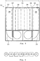
- Fig. 5 illustrates an alternatively constructed device 32, wherein, basically, the air treatment device 2 in Figs. 1a and 1b is doubled to its width L, such that centrally, a doubled first filter chamber 34 is arranged for incoming air, whereby the air passes pre-filters 35 arranged on the respective two longer sides of the housing and thereafter pass through either one or two doubled tubular first carbon filters 36.
- two fans are arranged which supply each half of the device.
- Two separate second filter chambers are arranged, namely, on a second side of a respective separation wall 42 at each short side of the device 32 each including a pair of tubular second carbon filters 38.
- the invention gives great possibilities to achieve very advantageous and requirement-controlled filtering of air in a building. It is thus achieved through the inventive arrangement good filter efficiency since large filter surface areas are allowed and thereby low air resistance within the frame of reasonable physical dimensions. Good noise properties can also be obtained in a device and a method according to the invention.
- the pre-filters as well as the after filters can include sideward arranged "parallel" filter elements of different character according to what is described above, which can be tuned to each other for control of the flow through the different elements.
- the application thus also includes tubular first and second carbon filters being comprised of one respective single element. It can also be possible to connect two "carbon filter tubes” that are tuned to each other with different characteristic axially to each other, tightly end to end and opening to opening.
- fans can be used such as axial, radial and centrifugal fans. Decisive for the choice of fan type is the application in question and particular prevailing requirements.
- the invention can be applied in connection with large central ventilation devices as well as for local room positioned units as well as also for portable air treatment units.
Landscapes
- Engineering & Computer Science (AREA)
- Chemical & Material Sciences (AREA)
- Combustion & Propulsion (AREA)
- Mechanical Engineering (AREA)
- General Engineering & Computer Science (AREA)
- Chemical Kinetics & Catalysis (AREA)
- General Chemical & Material Sciences (AREA)
- Physics & Mathematics (AREA)
- Geometry (AREA)
- Filtering Of Dispersed Particles In Gases (AREA)
Claims (13)
- Luftbehandlungsvorrichtung (2) mit einem Gehäuse (3), das ein eingeschlossenes Gebläse (4) aufweist, wobei das Gehäuse zum lösbaren Aufnehmen eines Einlassfiltermittels, das mit einer Ansaugseite (8) des Gebläses verbunden ist, und eines Auslassfiltermittels (13) des Gebläses angeordnet ist, dadurch gekennzeichnet,- dass das Gehäuse (3) erste Verbindungsmittel aufweist, die einerseits Elemente zum Zusammenwirken mit einem Vorfilter in der Form von wenigstens einem ersten Partikelfilter (5), andererseits Elemente zum Zusammenwirken mit wenigstens einem rohrförmigen ersten Kohlenstofffilter (6', 6") zum Koppeln desselben mit seiner Innenseite an die Ansaugseite des Gebläses und in einer Strömungsrichtung stromabwärts des Vorfilters aufweisen, und- dass das Gehäuse (3) zweite Kopplungsmittel aufweist, die einerseits Elemente zum Zusammenwirken mit wenigstens einem rohrförmigen zweiten Kohlenstofffilter (9', 9") zum Koppeln desselben mit seiner Innenseite an die Druckseite des Gebläses, andererseits Elemente zum Zusammenwirken mit einem Nachfilter (10) in der Form von wenigstens einem zweiten Partikelfilter aufweisen, derart, dass er, betrachtet in der Strömungsrichtung, stromabwärts des zweiten Kohlenstofffilters liegt.
- Luftbehandlungsvorrichtung nach Anspruch 1,
dadurch gekennzeichnet, dass das Gehäuse (3) mit einer ersten Filterkammer (7) zum Aufnehmen des bzw. der ersten Kohlenstofffilter und mit einer zweiten Filterkammer (11) zum Aufnehmen des bzw. der zweiten Kohlenstofffilter angeordnet ist, wobei die Filterkammern Seite an Seite und separat angeordnet sind. - Luftbehandlungsvorrichtung nach Anspruch 2, dadurch gekennzeichnet, dass die ersten und zweiten Kohlenstofffilter (6', 6", 9', 9") in angebrachtem Zustand in der jeweiligen Filterkammer mit parallelen Symmetrieachsen (A1, A2, A3, A4) angeordnet sind.
- Luftbehandlungsvorrichtung nach Anspruch 2 oder 3, dadurch gekennzeichnet, dass die Filterkammern (7,11) durch einen entfernbaren Wandabschnitt (15) bedienbar sind, der zu dem Gehäuse gehört.
- Luftbehandlungsvorrichtung nach einem der vorangehenden Ansprüche, dadurch gekennzeichnet, dass das Gebläse (4) in einer Gebläsekammer (12) angeordnet ist, die die Elemente zum Zusammenwirken mit wenigstens einem ersten Kohlenstofffilter und Elemente zum Zusammenwirken mit wenigstens einem zweiten Kohlenstofffilter aufweist.
- Luftbehandlungsvorrichtung nach Anspruch 5, dadurch gekennzeichnet, dass die Elemente zum Zusammenwirken mit dem ersten und zweiten Kohlenstofffilter an einer Wand angeordnet sind, die die Gebläsekammer (12) begrenzen.
- Luftbehandlungsvorrichtung nach einem der vorangehenden Ansprüche, dadurch gekennzeichnet, dass wenigstens eins der Elemente zum Zusammenwirken mit einem Vorfilter (5) und einem Nachfilter (10) zur Aufnahme eines plattenförmigen Filters angepasst ist.
- System zur Luftbehandlung, aufweisend eine Luftbehandlungsvorrichtung nach einem der Ansprüche 1-7, dadurch gekennzeichnet, dass es außerdem Folgendes aufweist:- wenigstens einen Vorfilter (5) in der Form von wenigstens einem ersten Partikelfilter,- wenigstens einen rohrförmigen ersten Kohlenstofffilter (6', 6"),- wenigstens einen rohrförmigen zweiten Kohlenstofffilter (9', 9"),- wenigstens einen Nachfilter (10) in der Form von wenigstens einem zweiten Partikelfilter.
- System zur Luftbehandlung nach Anspruch 8, dadurch gekennzeichnet, dass wenigstens eine der Gruppen:i) erster Partikelfilter,ii) erster Kohlenstofffilter,iii) zweiter Kohlenstofffilter,iv) zweiter Partikelfiltermehrere Filterelemente mit unterschiedlicher Charakteristik aufweist, die hinsichtlich des Luftdurchlasswiderstands aufeinander abgestimmt sind, um relative Luftströmung zwischen den mehreren Filterelementen zu steuern, um eine gewünschte Filtercharakteristik zu erlangen.
- System zur Luftbehandlung nach Anspruch 8 oder 9, dadurch gekennzeichnet, dass die ersten und zweiten Kohlenstofffilter (6', 6", 9', 9") im Wesentlichen kreiszylinderförmig sind.
- Verfahren zur Luftbehandlung, wobei die Luft:i) in wenigstens einem ersten Partikelfilter vorgefiltert wird,ii) in wenigstens einem rohrförmigen ersten Kohlenstofffilter gefiltert wird, derart, dass zu filternde Luft von außen und durch den ersten Kohlenstofffilter hinein strömen gelassen wird,- woraufhin die Luft ein Gebläse passiert, das die Luft antreibt,iii) in wenigstens einem rohrförmigen zweiten Kohlenstofffilter gefiltert wird, derart, dass zu filternde Luft von innen und durch den zweiten Kohlenstofffilter heraus strömen gelassen wird,iv) in wenigstens einem zweiten Partikelfilter nachgefiltert wird.
- Verfahren nach Anspruch 11, dadurch gekennzeichnet, dass die Luft durch Partikelfilter und/oder Kohlenstofffilters mit unterschiedlichen Filtercharakteristiken gefiltert wird.
- Verfahren nach Anspruch 11 oder 12,
dadurch gekennzeichnet, dass, wenn wenigstens eine der Gruppen:i) erster Partikelfilter,ii) erster Kohlenstofffilter,iii) zweiter Kohlenstofffilter,iv) zweiter Partikelfiltermehrere Filterelemente mit unterschiedlicher Charakteristik aufweist, relativer Luftstrom zwischen den mehreren Filterelementen gesteuert wird, um eine gewünschte Filtercharakteristik zu erlangen, indem sie hinsichtlich des Luftdurchlasswiderstands aufeinander abgestimmt werden.
Priority Applications (1)
| Application Number | Priority Date | Filing Date | Title |
|---|---|---|---|
| PL13742935T PL2809997T3 (pl) | 2012-01-31 | 2013-01-31 | Sposób i urządzenie do uzdatniania powietrza zawierające obudowę mającą wentylator, filtry cząsteczkowe i rurkowe filtry węglowe |
Applications Claiming Priority (2)
| Application Number | Priority Date | Filing Date | Title |
|---|---|---|---|
| SE1250067A SE537323C2 (sv) | 2012-01-31 | 2012-01-31 | Luftfiltersystem |
| PCT/SE2013/050080 WO2013115717A1 (en) | 2012-01-31 | 2013-01-31 | Method and device for air treatment including a housing having a fan, particle filters and tubular carbon filters. |
Publications (3)
| Publication Number | Publication Date |
|---|---|
| EP2809997A1 EP2809997A1 (de) | 2014-12-10 |
| EP2809997A4 EP2809997A4 (de) | 2016-01-27 |
| EP2809997B1 true EP2809997B1 (de) | 2017-04-12 |
Family
ID=48905850
Family Applications (1)
| Application Number | Title | Priority Date | Filing Date |
|---|---|---|---|
| EP13742935.3A Active EP2809997B1 (de) | 2012-01-31 | 2013-01-31 | Verfahren und vorrichtung zur luftbehandlung einschliesslich eines gehäuses mit einem gebläse, partikelfiltern und röhrenförmigen filtern |
Country Status (8)
| Country | Link |
|---|---|
| EP (1) | EP2809997B1 (de) |
| CN (1) | CN104246391B (de) |
| DK (1) | DK2809997T3 (de) |
| ES (1) | ES2632807T3 (de) |
| PL (1) | PL2809997T3 (de) |
| PT (1) | PT2809997T (de) |
| SE (1) | SE537323C2 (de) |
| WO (1) | WO2013115717A1 (de) |
Families Citing this family (4)
| Publication number | Priority date | Publication date | Assignee | Title |
|---|---|---|---|---|
| CN105327555A (zh) * | 2015-11-27 | 2016-02-17 | 苏州兴亚净化工程有限公司 | 一种改进的空气净化过滤装置 |
| GB2568462B (en) * | 2017-11-09 | 2023-04-12 | Polypipe Ltd | An active carbon filter for an air vent assembly |
| DE102018204630A1 (de) * | 2018-03-27 | 2019-10-02 | Filtration Group Gmbh | Belüftungseinrichtung zum Filtern von Luft und zum Abscheiden von Wasseraerosolen aus Luft |
| EP3801830A1 (de) * | 2018-06-11 | 2021-04-14 | Donaldson Company, Inc. | Filtermedien, filtermedienpacks und filterelemente |
Family Cites Families (9)
| Publication number | Priority date | Publication date | Assignee | Title |
|---|---|---|---|---|
| DE2846036A1 (de) * | 1978-10-23 | 1980-05-08 | Hoelter Heinz | Rohrfoermiger autofilter fuer personenschutz in kraftfahrzeugen |
| US4737173A (en) * | 1986-07-03 | 1988-04-12 | Amway Corporation | Room air treatment system |
| SE515895C2 (sv) * | 2000-02-28 | 2001-10-22 | Clair Finance Ab | Anordning, förfarande och system för luftfiltrering |
| CN100455456C (zh) * | 2000-03-09 | 2009-01-28 | 马里·德哈波特·林赛 | 用于机动车车厢的便携式空气净化器 |
| US6974197B1 (en) * | 2001-02-06 | 2005-12-13 | The United States Of America As Represented By The Secretary Of The Army | Portable glovebox and filtration system |
| SE0402604D0 (sv) * | 2004-10-27 | 2004-10-27 | Camfil Ab | Air filter unit |
| US20070251876A1 (en) * | 2006-04-28 | 2007-11-01 | Krogue John A | Hybrid filter element and method |
| US9435552B2 (en) * | 2007-12-14 | 2016-09-06 | Ge-Hitachi Nuclear Energy Americas Llc | Air filtration and handling for nuclear reactor habitability area |
| CN201153595Y (zh) * | 2008-01-08 | 2008-11-26 | 蔡贤能 | 鞋机用空气净化系统 |
-
2012
- 2012-01-31 SE SE1250067A patent/SE537323C2/sv unknown
-
2013
- 2013-01-31 EP EP13742935.3A patent/EP2809997B1/de active Active
- 2013-01-31 PT PT137429353T patent/PT2809997T/pt unknown
- 2013-01-31 CN CN201380007572.6A patent/CN104246391B/zh active Active
- 2013-01-31 WO PCT/SE2013/050080 patent/WO2013115717A1/en not_active Ceased
- 2013-01-31 PL PL13742935T patent/PL2809997T3/pl unknown
- 2013-01-31 DK DK13742935.3T patent/DK2809997T3/en active
- 2013-01-31 ES ES13742935.3T patent/ES2632807T3/es active Active
Non-Patent Citations (1)
| Title |
|---|
| None * |
Also Published As
| Publication number | Publication date |
|---|---|
| ES2632807T3 (es) | 2017-09-15 |
| PL2809997T3 (pl) | 2017-12-29 |
| SE537323C2 (sv) | 2015-04-07 |
| WO2013115717A1 (en) | 2013-08-08 |
| EP2809997A1 (de) | 2014-12-10 |
| PT2809997T (pt) | 2017-07-14 |
| DK2809997T3 (en) | 2017-07-24 |
| CN104246391A (zh) | 2014-12-24 |
| SE1250067A1 (sv) | 2013-08-01 |
| EP2809997A4 (de) | 2016-01-27 |
| CN104246391B (zh) | 2017-03-22 |
Similar Documents
| Publication | Publication Date | Title |
|---|---|---|
| US9043989B2 (en) | Method and apparatus for providing clean air to animal enclosures | |
| US7425226B2 (en) | Fluid filter with canted fanfold pleats | |
| US7524362B2 (en) | Modular filter assembly | |
| CA2813274C (en) | Filter structure for removing contaminants from stream of fluid | |
| EP2809997B1 (de) | Verfahren und vorrichtung zur luftbehandlung einschliesslich eines gehäuses mit einem gebläse, partikelfiltern und röhrenförmigen filtern | |
| US7833308B2 (en) | Filter assembly with multiple inlets and multiple filter members | |
| KR101719671B1 (ko) | 필터 엘리먼트 | |
| CN202158602U (zh) | 双c型油烟分离装置 | |
| EP4323086A1 (de) | Luftbehandlungsmodul | |
| EP4408566B1 (de) | Luftreinigungseinrichtung zur reinigung von luft sowie verfahren zum betreiben einer luftreinigungseinrichtung | |
| CN205372682U (zh) | 油烟机用石墨烯基吸油海绵 | |
| CN209020074U (zh) | 一种汽车空调滤清器 | |
| KR100503505B1 (ko) | 공기청정기 | |
| EP3446767B1 (de) | Koaleszenzvorfilterelement für eine turbinenfilterkassette und kombinationsfilter damit | |
| CN101373088A (zh) | 一种新风换气机 | |
| CN214182266U (zh) | 一种大风量过滤器 | |
| US11752462B2 (en) | Effluent processing apparatus and method for a vehicle air brake charging system | |
| CN212511304U (zh) | 内循环油烟机 | |
| RU82427U1 (ru) | Пылеулавливающий аппарат для сухой очистки газов | |
| KR200419501Y1 (ko) | 공조기용 에어필터 | |
| CN205199147U (zh) | 多层空气过滤装置及电器 | |
| CN106694228A (zh) | 一种空气过滤装置 | |
| CN106369691A (zh) | 自动空气洁净器 | |
| CN205412557U (zh) | 工业用的新型压缩空气净化设备 | |
| HK40044929A (en) | An air filter and its method for manufacturing |
Legal Events
| Date | Code | Title | Description |
|---|---|---|---|
| PUAI | Public reference made under article 153(3) epc to a published international application that has entered the european phase |
Free format text: ORIGINAL CODE: 0009012 |
|
| 17P | Request for examination filed |
Effective date: 20140807 |
|
| AK | Designated contracting states |
Kind code of ref document: A1 Designated state(s): AL AT BE BG CH CY CZ DE DK EE ES FI FR GB GR HR HU IE IS IT LI LT LU LV MC MK MT NL NO PL PT RO RS SE SI SK SM TR |
|
| AX | Request for extension of the european patent |
Extension state: BA ME |
|
| DAX | Request for extension of the european patent (deleted) | ||
| RA4 | Supplementary search report drawn up and despatched (corrected) |
Effective date: 20160107 |
|
| RIC1 | Information provided on ipc code assigned before grant |
Ipc: F24F 3/16 20060101ALI20151222BHEP Ipc: F24F 13/28 20060101AFI20151222BHEP Ipc: B01D 46/24 20060101ALI20151222BHEP Ipc: B01D 46/00 20060101ALI20151222BHEP |
|
| GRAP | Despatch of communication of intention to grant a patent |
Free format text: ORIGINAL CODE: EPIDOSNIGR1 |
|
| STAA | Information on the status of an ep patent application or granted ep patent |
Free format text: STATUS: GRANT OF PATENT IS INTENDED |
|
| INTG | Intention to grant announced |
Effective date: 20161102 |
|
| GRAS | Grant fee paid |
Free format text: ORIGINAL CODE: EPIDOSNIGR3 |
|
| GRAA | (expected) grant |
Free format text: ORIGINAL CODE: 0009210 |
|
| STAA | Information on the status of an ep patent application or granted ep patent |
Free format text: STATUS: THE PATENT HAS BEEN GRANTED |
|
| AK | Designated contracting states |
Kind code of ref document: B1 Designated state(s): AL AT BE BG CH CY CZ DE DK EE ES FI FR GB GR HR HU IE IS IT LI LT LU LV MC MK MT NL NO PL PT RO RS SE SI SK SM TR |
|
| REG | Reference to a national code |
Ref country code: GB Ref legal event code: FG4D |
|
| REG | Reference to a national code |
Ref country code: CH Ref legal event code: EP |
|
| REG | Reference to a national code |
Ref country code: IE Ref legal event code: FG4D |
|
| REG | Reference to a national code |
Ref country code: AT Ref legal event code: REF Ref document number: 884312 Country of ref document: AT Kind code of ref document: T Effective date: 20170515 |
|
| REG | Reference to a national code |
Ref country code: DE Ref legal event code: R096 Ref document number: 602013019778 Country of ref document: DE |
|
| REG | Reference to a national code |
Ref country code: PT Ref legal event code: SC4A Ref document number: 2809997 Country of ref document: PT Date of ref document: 20170714 Kind code of ref document: T Free format text: AVAILABILITY OF NATIONAL TRANSLATION Effective date: 20170710 |
|
| REG | Reference to a national code |
Ref country code: NL Ref legal event code: FP |
|
| REG | Reference to a national code |
Ref country code: DK Ref legal event code: T3 Effective date: 20170712 |
|
| REG | Reference to a national code |
Ref country code: SE Ref legal event code: TRGR |
|
| REG | Reference to a national code |
Ref country code: LT Ref legal event code: MG4D |
|
| REG | Reference to a national code |
Ref country code: NO Ref legal event code: T2 Effective date: 20170412 |
|
| REG | Reference to a national code |
Ref country code: ES Ref legal event code: FG2A Ref document number: 2632807 Country of ref document: ES Kind code of ref document: T3 Effective date: 20170915 |
|
| PG25 | Lapsed in a contracting state [announced via postgrant information from national office to epo] |
Ref country code: LT Free format text: LAPSE BECAUSE OF FAILURE TO SUBMIT A TRANSLATION OF THE DESCRIPTION OR TO PAY THE FEE WITHIN THE PRESCRIBED TIME-LIMIT Effective date: 20170412 Ref country code: HR Free format text: LAPSE BECAUSE OF FAILURE TO SUBMIT A TRANSLATION OF THE DESCRIPTION OR TO PAY THE FEE WITHIN THE PRESCRIBED TIME-LIMIT Effective date: 20170412 Ref country code: GR Free format text: LAPSE BECAUSE OF FAILURE TO SUBMIT A TRANSLATION OF THE DESCRIPTION OR TO PAY THE FEE WITHIN THE PRESCRIBED TIME-LIMIT Effective date: 20170713 |
|
| PG25 | Lapsed in a contracting state [announced via postgrant information from national office to epo] |
Ref country code: IS Free format text: LAPSE BECAUSE OF FAILURE TO SUBMIT A TRANSLATION OF THE DESCRIPTION OR TO PAY THE FEE WITHIN THE PRESCRIBED TIME-LIMIT Effective date: 20170812 Ref country code: BG Free format text: LAPSE BECAUSE OF FAILURE TO SUBMIT A TRANSLATION OF THE DESCRIPTION OR TO PAY THE FEE WITHIN THE PRESCRIBED TIME-LIMIT Effective date: 20170712 Ref country code: RS Free format text: LAPSE BECAUSE OF FAILURE TO SUBMIT A TRANSLATION OF THE DESCRIPTION OR TO PAY THE FEE WITHIN THE PRESCRIBED TIME-LIMIT Effective date: 20170412 Ref country code: LV Free format text: LAPSE BECAUSE OF FAILURE TO SUBMIT A TRANSLATION OF THE DESCRIPTION OR TO PAY THE FEE WITHIN THE PRESCRIBED TIME-LIMIT Effective date: 20170412 |
|
| REG | Reference to a national code |
Ref country code: SK Ref legal event code: T3 Ref document number: E 24708 Country of ref document: SK |
|
| REG | Reference to a national code |
Ref country code: DE Ref legal event code: R097 Ref document number: 602013019778 Country of ref document: DE |
|
| REG | Reference to a national code |
Ref country code: FR Ref legal event code: PLFP Year of fee payment: 6 |
|
| PG25 | Lapsed in a contracting state [announced via postgrant information from national office to epo] |
Ref country code: CZ Free format text: LAPSE BECAUSE OF FAILURE TO SUBMIT A TRANSLATION OF THE DESCRIPTION OR TO PAY THE FEE WITHIN THE PRESCRIBED TIME-LIMIT Effective date: 20170412 Ref country code: RO Free format text: LAPSE BECAUSE OF FAILURE TO SUBMIT A TRANSLATION OF THE DESCRIPTION OR TO PAY THE FEE WITHIN THE PRESCRIBED TIME-LIMIT Effective date: 20170412 Ref country code: EE Free format text: LAPSE BECAUSE OF FAILURE TO SUBMIT A TRANSLATION OF THE DESCRIPTION OR TO PAY THE FEE WITHIN THE PRESCRIBED TIME-LIMIT Effective date: 20170412 |
|
| PLBE | No opposition filed within time limit |
Free format text: ORIGINAL CODE: 0009261 |
|
| STAA | Information on the status of an ep patent application or granted ep patent |
Free format text: STATUS: NO OPPOSITION FILED WITHIN TIME LIMIT |
|
| PG25 | Lapsed in a contracting state [announced via postgrant information from national office to epo] |
Ref country code: SM Free format text: LAPSE BECAUSE OF FAILURE TO SUBMIT A TRANSLATION OF THE DESCRIPTION OR TO PAY THE FEE WITHIN THE PRESCRIBED TIME-LIMIT Effective date: 20170412 |
|
| 26N | No opposition filed |
Effective date: 20180115 |
|
| PG25 | Lapsed in a contracting state [announced via postgrant information from national office to epo] |
Ref country code: SI Free format text: LAPSE BECAUSE OF FAILURE TO SUBMIT A TRANSLATION OF THE DESCRIPTION OR TO PAY THE FEE WITHIN THE PRESCRIBED TIME-LIMIT Effective date: 20170412 |
|
| PG25 | Lapsed in a contracting state [announced via postgrant information from national office to epo] |
Ref country code: LU Free format text: LAPSE BECAUSE OF NON-PAYMENT OF DUE FEES Effective date: 20180131 |
|
| PG25 | Lapsed in a contracting state [announced via postgrant information from national office to epo] |
Ref country code: MC Free format text: LAPSE BECAUSE OF FAILURE TO SUBMIT A TRANSLATION OF THE DESCRIPTION OR TO PAY THE FEE WITHIN THE PRESCRIBED TIME-LIMIT Effective date: 20170412 |
|
| REG | Reference to a national code |
Ref country code: AT Ref legal event code: UEP Ref document number: 884312 Country of ref document: AT Kind code of ref document: T Effective date: 20170412 |
|
| PG25 | Lapsed in a contracting state [announced via postgrant information from national office to epo] |
Ref country code: MT Free format text: LAPSE BECAUSE OF NON-PAYMENT OF DUE FEES Effective date: 20180131 |
|
| PG25 | Lapsed in a contracting state [announced via postgrant information from national office to epo] |
Ref country code: HU Free format text: LAPSE BECAUSE OF FAILURE TO SUBMIT A TRANSLATION OF THE DESCRIPTION OR TO PAY THE FEE WITHIN THE PRESCRIBED TIME-LIMIT; INVALID AB INITIO Effective date: 20130131 |
|
| PG25 | Lapsed in a contracting state [announced via postgrant information from national office to epo] |
Ref country code: CY Free format text: LAPSE BECAUSE OF FAILURE TO SUBMIT A TRANSLATION OF THE DESCRIPTION OR TO PAY THE FEE WITHIN THE PRESCRIBED TIME-LIMIT Effective date: 20170412 Ref country code: MK Free format text: LAPSE BECAUSE OF NON-PAYMENT OF DUE FEES Effective date: 20170412 |
|
| PG25 | Lapsed in a contracting state [announced via postgrant information from national office to epo] |
Ref country code: AL Free format text: LAPSE BECAUSE OF FAILURE TO SUBMIT A TRANSLATION OF THE DESCRIPTION OR TO PAY THE FEE WITHIN THE PRESCRIBED TIME-LIMIT Effective date: 20170412 |
|
| REG | Reference to a national code |
Ref country code: GB Ref legal event code: 732E Free format text: REGISTERED BETWEEN 20220721 AND 20220727 |
|
| REG | Reference to a national code |
Ref country code: NO Ref legal event code: CREP Representative=s name: PLOUGMANN VINGTOFT, POSTBOKS 1003 SENTRUM, 0104 Ref country code: NO Ref legal event code: CHAD Owner name: CAMFIL AB, SE |
|
| REG | Reference to a national code |
Ref country code: FI Ref legal event code: PCE Owner name: CAMFIL AB |
|
| REG | Reference to a national code |
Ref country code: NL Ref legal event code: PD Owner name: CAMFIL AB; SE Free format text: DETAILS ASSIGNMENT: CHANGE OF OWNER(S), ASSIGNMENT; FORMER OWNER NAME: CAMFIL VENTURES AKTIEBOLAG Effective date: 20221004 Ref country code: NL Ref legal event code: HC Owner name: CAMFIL VENTURES AKTIEBOLAG; SE Free format text: DETAILS ASSIGNMENT: CHANGE OF OWNER(S), CHANGE OF OWNER(S) NAME; FORMER OWNER NAME: CAMFIL AB Effective date: 20221004 Ref country code: SK Ref legal event code: TC4A Ref document number: E 24708 Country of ref document: SK Owner name: CAMFIL VENTURES AB, STOCKHOLM, SE Effective date: 20220921 Ref country code: SK Ref legal event code: PC4A Ref document number: E 24708 Country of ref document: SK Owner name: CAMFIL AB, STOCKHOLM, SE Free format text: FORMER OWNER: CAMFIL VENTURES AB, STOCKHOLM, SE Effective date: 20220921 |
|
| REG | Reference to a national code |
Ref country code: DE Ref legal event code: R081 Ref document number: 602013019778 Country of ref document: DE Owner name: CAMFIL AB, SE Free format text: FORMER OWNER: CAMFIL VENTURES AB, STOCKHOLM, SE Ref country code: DE Ref legal event code: R081 Ref document number: 602013019778 Country of ref document: DE Owner name: CAMFIL AB, SE Free format text: FORMER OWNER: CAMFIL AB, STOCKHOLM, SE Ref country code: DE Ref legal event code: R082 Ref document number: 602013019778 Country of ref document: DE |
|
| REG | Reference to a national code |
Ref country code: BE Ref legal event code: PD Owner name: CAMFIL AB; SE Free format text: DETAILS ASSIGNMENT: CHANGE OF OWNER(S), ASSIGNMENT; FORMER OWNER NAME: CAMFIL VENTURES AB Effective date: 20220725 Ref country code: BE Ref legal event code: HC Owner name: CAMFIL VENTURES AB; SE Free format text: DETAILS ASSIGNMENT: CHANGE OF OWNER(S), CHANGE OF OWNER(S) NAME; FORMER OWNER NAME: CAMFIL AB Effective date: 20220725 |
|
| REG | Reference to a national code |
Ref country code: ES Ref legal event code: PC2A Owner name: CAMFIL AB Effective date: 20221216 |
|
| P01 | Opt-out of the competence of the unified patent court (upc) registered |
Effective date: 20230613 |
|
| PGFP | Annual fee paid to national office [announced via postgrant information from national office to epo] |
Ref country code: PT Payment date: 20250123 Year of fee payment: 13 Ref country code: DE Payment date: 20250121 Year of fee payment: 13 |
|
| PGFP | Annual fee paid to national office [announced via postgrant information from national office to epo] |
Ref country code: DK Payment date: 20250124 Year of fee payment: 13 Ref country code: FI Payment date: 20250124 Year of fee payment: 13 |
|
| PGFP | Annual fee paid to national office [announced via postgrant information from national office to epo] |
Ref country code: ES Payment date: 20250226 Year of fee payment: 13 |
|
| PGFP | Annual fee paid to national office [announced via postgrant information from national office to epo] |
Ref country code: IE Payment date: 20250130 Year of fee payment: 13 Ref country code: SE Payment date: 20250121 Year of fee payment: 13 |
|
| PGFP | Annual fee paid to national office [announced via postgrant information from national office to epo] |
Ref country code: NO Payment date: 20250124 Year of fee payment: 13 |
|
| PGFP | Annual fee paid to national office [announced via postgrant information from national office to epo] |
Ref country code: AT Payment date: 20250122 Year of fee payment: 13 Ref country code: CH Payment date: 20250201 Year of fee payment: 13 Ref country code: BE Payment date: 20250121 Year of fee payment: 13 |
|
| PGFP | Annual fee paid to national office [announced via postgrant information from national office to epo] |
Ref country code: PL Payment date: 20250123 Year of fee payment: 13 Ref country code: FR Payment date: 20250127 Year of fee payment: 13 |
|
| PGFP | Annual fee paid to national office [announced via postgrant information from national office to epo] |
Ref country code: SK Payment date: 20250128 Year of fee payment: 13 Ref country code: IT Payment date: 20250123 Year of fee payment: 13 Ref country code: GB Payment date: 20250128 Year of fee payment: 13 |
|
| PGFP | Annual fee paid to national office [announced via postgrant information from national office to epo] |
Ref country code: TR Payment date: 20250129 Year of fee payment: 13 |
|
| REG | Reference to a national code |
Ref country code: CH Ref legal event code: U11 Free format text: ST27 STATUS EVENT CODE: U-0-0-U10-U11 (AS PROVIDED BY THE NATIONAL OFFICE) Effective date: 20260201 |
|
| PGFP | Annual fee paid to national office [announced via postgrant information from national office to epo] |
Ref country code: NL Payment date: 20260121 Year of fee payment: 14 |