EP2809471B1 - Werkzeug zur spanlosen erzeugung oder nachbearbeitung eines gewindes an einem werkstück, insbesondere gewindefurcher oder gewindeformer - Google Patents
Werkzeug zur spanlosen erzeugung oder nachbearbeitung eines gewindes an einem werkstück, insbesondere gewindefurcher oder gewindeformer Download PDFInfo
- Publication number
- EP2809471B1 EP2809471B1 EP12794292.8A EP12794292A EP2809471B1 EP 2809471 B1 EP2809471 B1 EP 2809471B1 EP 12794292 A EP12794292 A EP 12794292A EP 2809471 B1 EP2809471 B1 EP 2809471B1
- Authority
- EP
- European Patent Office
- Prior art keywords
- thread
- tool
- pressing
- curve
- along
- Prior art date
- Legal status (The legal status is an assumption and is not a legal conclusion. Google has not performed a legal analysis and makes no representation as to the accuracy of the status listed.)
- Active
Links
Images




Classifications
-
- B—PERFORMING OPERATIONS; TRANSPORTING
- B23—MACHINE TOOLS; METAL-WORKING NOT OTHERWISE PROVIDED FOR
- B23G—THREAD CUTTING; WORKING OF SCREWS, BOLT HEADS, OR NUTS, IN CONJUNCTION THEREWITH
- B23G7/00—Forming thread by means of tools similar both in form and in manner of use to thread-cutting tools, but without removing any material
- B23G7/02—Tools for this purpose
Definitions
- the invention relates to a tool for the non-cutting production or post-processing of a thread on a workpiece, in particular a thread former or thread former.
- the thread is produced without cutting by reshaping the workpiece, in that so-called pressure studs, also referred to as shaped wedges or teeth, cause the workpiece to be cold deformed by pressure.
- pressure studs also referred to as shaped wedges or teeth
- the advantage of these tools is that the deformation of the surface and the associated hardening increase the hardness of the material in the area of the thread profile and thus create a more wear-resistant thread than when machining threads.
- Known thread formers in particular for producing internal threads, comprise a shaft and a working area.
- the shaft is generally cylindrical and is received and held in the chuck of a thread-producing device with its end facing away from the workpiece.
- the working area in particular the shaping area, is located on the side of the thread groove opposite the shaft.
- the shaping area is provided with a shaping curve which runs spirally around the circumference and along which the pressure lugs are formed as elevations.
- the pitch angle between two press studs which follow one another along the shaping curve is the same for all press studs.
- An imaginary rectilinear connecting lines between the tips of the press studs along the shaping curve form in a projection onto a surface perpendicular to the tool axis, with the exception of radial deviations, essentially a regular n-corner, with n press studs being arranged around the tool axis per revolution of the shaping curve. Every nth press stud is arranged along a straight line parallel to the tool axis; these press studs arranged along a straight line form a so-called press web.
- the present invention is based on the object of specifying a novel tool for the non-cutting production of a thread, in particular a novel thread taper or thread former.
- the tool according to the invention comprises at least one shaping region which can be rotated or rotated about a tool axis for non-cutting production or post-processing of the thread, in particular an internal thread.
- the shaping region has a plurality of press studs which protrude radially outward from the tool axis or protrude for producing or reworking the thread by pressing the press studs into the workpiece surface.
- the pressure studs are arranged in succession along a shaping curve that essentially rotates around the tool axis in a spiral (or helical or helical) manner.
- the slope of the shaping curve essentially corresponds to the slope of the thread to be produced or reworked.
- the pitch angle between a first of the press studs and one on this first press stud along the Shaping curve following second press studs differs from the pitch angle between the second press stud and a third press stud following the second press stud along the shaping curve.
- the pitch angle is defined in a projection of the respective press studs into a plane perpendicular to the tool axis.
- the apex of the pitch angle between two press studs lies on the tool axis and its two legs pass through the tips of the two press studs considered, the tip of a press stud being understood as the position of the press stud with the greatest distance from the tool axis.
- the invention is characterized in that the pressure tunnels are randomly distributed along the shaping curve in such a way that there is no repeating sequence of successive pitch angles, each pitch angle being between 2 ° and 178 °, in particular between 10 ° and 170 °, preferably between 20 ° and 120 °.
- the tool has no pressure bars. This random distribution leads to an uneven distribution of the pressure lugs on the circumference, without repeating the arrangement from circulation to circulation of the shaping curve.
- the advantages of the tool according to the invention lie in a good shaping behavior and in a high accuracy of the threads produced with this tool, since the tool is guided precisely when machining a workpiece due to the arrangement of the press studs according to the invention.
- the amount of the difference between the two different pitch angles is between 2 ° and 45 °, in particular between 5 ° and 15 °.
- a further embodiment provides that at least three successive pitch angles differ between press studs which follow one another along the shaping curve, in particular by at least 2 °, preferably by at least 5 °.
- FIG. 1 shows a thread former 1 known per se, which comprises a tool shank 2 and two working areas, namely a shaping area 3 and a calibration area 4. Shaping area 3 and calibration area 4 form a shaping area 5 of the thread turret 1.
- a tool axis A which at the same time represents an axis of rotation of the thread turret 1, runs parallel to the longitudinal extent of the thread turret 1 through the center of the thread turret 1.
- a feed direction V of the thread turret 1 runs parallel to the tool axis A and is in FIG. 1 indicated by the direction of the arrow.
- the thread former 1 is used for non-cutting internal thread production.
- the tool shank 2 can be cylindrical, for example, and generally carries a square (not shown here) on the side introduced into the chuck for the transmission of the torque.
- the tool shank 2 is here firmly connected to the adjacent shaping area 5, in particular the tool shank 2 and the shaping area 5 are made in one piece.
- the shaping region 5 In a projection onto a surface perpendicular to the tool axis A, the shaping region 5 has a polygonal shape which has approximately the shape of a triangle with rounded corners and rounded connecting lines between the corners.
- press studs 7 are formed along a shaping curve 6 on a tool core as shaping thread.
- the shaping curve 6 runs spirally or helically, i.e. with an incline, around the tool axis A.
- the press studs 7 each have a tip 8 (also: head) at their free outer end.
- the pressure lugs 7 are arranged along the shaping curve 6 and thus axially offset along the tool axis A due to the slope of the shaping curve 6.
- Each revolution, that is to say each turn, of the shaping curve 6 around the tool axis A in the illustrated case comprises three press studs 7. All third press studs 7 of the press studs 7 immediately following one another along the shaping curve are arranged with their tip 8 in a plane that also includes the tool axis A contains.
- thread formers in alternative embodiments can also have several press studs 7 per thread, for example four or five or six or seven or eight or nine or ten.
- the press studs 7 of the shaping region 3 form a thread in the inner wall of the bore.
- the press studs 7 following one another along the shaping curve 6 penetrate into the workpiece surface until a last press stud 7 of the shaping region 3 forms the thread in its full depth and width. If the thread turret 1 rotates further in the feed direction V, the subsequent press studs 7 of the calibration area 4 calibrate and smooth the thread (the threads) or thread grooves).
- the press studs 7 in the calibration area 4 are therefore precisely matched in their dimensions and their shape to the thread to be produced.
- FIG 2 shows a perspective view schematically a part of another known embodiment of a thread former 1.
- the tool axis A and the feed direction V are shown.
- a shaping area 5 has press studs 7 which are arranged along a shaping curve 6.
- the tips 8 of the press studs 7 can be seen in each case.
- seven press studs are arranged per revolution of the shaping curve 6 about the tool axis A.
- straight connecting lines between the tips 8 of the press studs 7 along the shaping curve 6 essentially form a regular heptagon in a projection onto a surface perpendicular to the tool axis A, except for radial deviations, particularly in the case of press studs 7 near the tool tip.
- the press studs 7 are arranged such that each seventh press stud 7 lies in a plane that also contains the tool axis A.
- the seventh pressure tunnels 7 are arranged along a line (straight line), except for radial deviations. During a revolution around the tool 1 along the shaping curve 6, seven press studs 7 are detected.
- the press studs are distributed uniformly around the circumference of the shaping region 5, that is to say imaginary straight-line connecting lines between the tips 8 of the press studs 7 along the shaping curve 6 essentially form a projection onto a surface perpendicular to the tool axis A except for radial deviations a regular n-corner, with n pressure lugs per revolution of the shaping curve 6 being arranged around the tool axis A.
- the pitch angle between each of the press studs following the shaping curve 6 is the same for all press studs.
- the pitch angle t1 between a first of the press studs 7a and a second press stud 7b following this first press stud 7a along the shaping curve 6 differs from the pitch angle t2 between the second press stud 7b and a third following the second press stud 7b along the shaping curve 6 Press studs 7c.
- FIG 3 illustrates this in a projection display.
- the projection of an exemplary embodiment of a tool 1 is shown in a plane perpendicular to the tool axis, in the viewing direction against a feed direction of the tool.
- Three pressure lugs 7a, 7b, 7c, which follow one another along the shaping curve, can be seen, the tips 8 of which are each shown as the most protruding radial elevation.
- the pitch angles t1 and t2 are shown between these tips 8, the pitch angle t1 between the tips 8 of the first pressure stud 7a and the second pressure stud 7b being greater than the pitch angle t2 between the tips 8 of the second pressure stud 7b and the third pressure stud 7c.
- the example shown is a tool 1 with eight press studs per revolution of the shaping curve 6.
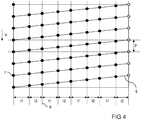
- FIG 4 to 6 illustrate the arrangement of the press studs 7 on the basis of development representations of parts of the shaping area of various exemplary embodiments of tools, only FIG 6 relates to a tool according to the invention.
- the pitch angles t1, t2, ... are shown schematically by double arrows.
- the feed direction V of the tool is entered in each case.
- the shaping curve 6, along which the pressure cleats 7 are arranged, can be seen in each case.
- the thread pitch P of the shaping curve 6 is in 4 to 6 registered.
- a line going from the left side of the diagram to the right side of the diagram corresponds to a revolution of the shaping curve around the tool axis A.
- FIG 4 shows an arrangement of press studs 7 along the shaping curve 6, in which two different pitch angles t1 and t2 alternate between successive press studs 7 along the shaping curve 6.
- the press studs 7 are arranged such that each eighth press stud 7 lies in a plane that also contains the tool axis A.
- the eighth press studs 7 are arranged essentially along a straight line 9. These lines or straight lines 9 are also referred to as push bars.
- FIG 5 shows an arrangement of press studs 7 along the shaping curve 6, in which all pitch angles t1, t2, ..., t8 between successive press studs 7 of a revolution of the shaping curve 6 around the tool axis A differ from one another.
- the pressure tunnels 7 are, however, as in the example FIG 4 Arranged in such a way that every eighth pressure lug 7 lies in a plane which also contains the tool axis A, that is to say the eighth pressure lugs 7 are arranged essentially along a straight line 9 and thus as straight-line pressure webs. This results in a sequence of successive different pitch angles t1, t2,..., T8 between press studs 7 which follow one another along the shaping curve 6 and which is repeated continuously along the shaping curve 6.
- FIG 6 shows in contrast to FIG 4 and FIG 5 an embodiment according to the invention, in which the press studs 7 are distributed so randomly along the shaping curve 6 that there is no repetitive sequence of successive ones Pitch angles exist.
- the pressure tunnels 7 are arranged randomly along the shaping curve, taking certain boundary conditions into account, the pitch angles differ accordingly without a systematic being recognizable.
- One in FIG 6 A recognizable boundary condition in the arrangement is that the circumference of the shaping region should be covered as uniformly as possible in order to achieve a uniform distribution of the forces occurring during shaping and thus to ensure a straight feed.
- the press studs are arranged such that at least approximately eight plus / minus one press stud 7 are provided per revolution of the shaping curve 6.
- tool designs are analogous to the examples according to 4 to 6 also possible with a different number of press studs per revolution of the shaping curve around the tool axis, for example with three or four or five or six or seven or nine or ten press studs per revolution.
- a radial offset of the press studs can be provided, in particular towards the end face of the tool.
Landscapes
- Engineering & Computer Science (AREA)
- Mechanical Engineering (AREA)
- Milling Processes (AREA)
- Forging (AREA)
- Cutting Tools, Boring Holders, And Turrets (AREA)
- Treatment Of Fiber Materials (AREA)
- Mounting, Exchange, And Manufacturing Of Dies (AREA)
- Perforating, Stamping-Out Or Severing By Means Other Than Cutting (AREA)
Description
- Die Erfindung betrifft ein Werkzeug zur spanlosen Erzeugung oder Nachbearbeitung eines Gewindes an einem Werkstück, insbesondere einen Gewindefurcher oder Gewindeformer.
- Bei diesen Werkzeugen erfolgt die Gewindeerzeugung spanlos mittels Umformung des Werkstücks, indem sogenannte Drückstollen, auch als Formkeile oder Zähne bezeichnet, durch Druck eine Kaltverformung des Werkstücks bewirken. Der Vorteil dieser Werkzeuge ist, dass durch die Verformung der Oberfläche und die damit verbundene Verfestigung die Härte des Werkstoffs im Bereich des Gewindeprofils ansteigt und somit ein verschleißfesteres Gewinde als bei spanender Gewindeerzeugung entsteht.
- Bekannte Gewindefurcher, insbesondere zur Innengewindeerzeugung, umfassen einen Schaft und einen Arbeitsbereich. Der Schaft ist in der Regel zylindrisch ausgeführt und mit seinem dem Werkstück abgewandten Ende im Spannfutter einer Gewindeerzeugungseinrichtung aufgenommen und gehalten. Der Arbeitsbereich, insbesondere der Formungsbereich, befindet sich auf der dem Schaft gegenüberliegenden Seite des Gewindefurchers.
- Der Formungsbereich ist mit einer entlang des Umfangs spiralförmig umlaufenden Formgebungskurve versehen, entlang der als Erhöhungen die Drückstollen ausgebildet sind.
- Bei bekannten Gewindefurchern ist der Teilungswinkel zwischen zwei jeweils entlang der Formgebungskurve aufeinanderfolgenden Drückstollen für alle Drückstollen gleich groß. Eine gedachte geradlinige Verbindungslinien zwischen den Spitzen der Drückstollen entlang der Formgebungskurve bilden in einer Projektion auf eine Fläche senkrecht zur Werkzeugachse bis auf radiale Abweichungen im Wesentlichen ein regelmäßiges n-Eck, wobei n Drückstollen pro Umlauf der Formgebungskurve um die Werkzeugachse angeordnet sind. Jeder n-te Drückstollen ist entlang einer Geraden parallel zur Werkzeugachse angeordnet, diese entlang einer Geraden angeordneten Drückstollen bilden einen sogenannten Drücksteg.
- Als weiteren Stand der Technik verweisen wir auf
DE 10 2008 053772 A1 ,DE 10 2006 015367 A1 undDE 10 2005 051174 A1 . - Der vorliegenden Erfindung liegt die Aufgabe zugrunde, ein neuartiges Werkzeug zur spanlosen Erzeugung eines Gewindes, insbesondere einen neuartigen Gewindefurcher oder Gewindeformer, anzugeben.
- Diese Aufgabe wird gelöst durch die Merkmale des Anspruchs 1. Vorteilhafte Ausgestaltungen und Weiterbildungen sind in den abhängigen Ansprüchen angegeben.
- Das Werkzeug gemäß der Erfindung umfasst mindestens einen um eine Werkzeugachse drehbaren oder drehenden Formungsbereich zur spanlosen Erzeugung oder Nachbearbeitung des Gewindes, insbesondere eines Innengewindes. Der Formungsbereich weist mehrere radial von der Werkzeugachse weg nach außen ragende oder vorstehende Drückstollen auf zum Erzeugen oder Nachbearbeiten des Gewindes durch Eindrücken der Drückstollen in die Werkstückoberfläche. Die Drückstollen sind entlang einer die Werkzeugachse im Wesentlichen spiralförmig (oder schraubenförmig oder helixförmig) umlaufenden Formgebungskurve aufeinanderfolgend angeordnet. Die Steigung der Formgebungskurve entspricht im Wesentlichen der Steigung des zu erzeugenden oder nachzuarbeitenden Gewindes.
- Gemäß der Erfindung ist vorgesehen, dass der Teilungswinkel zwischen einem ersten der Drückstollen und einem auf diesen ersten Drückstollen entlang der Formgebungskurve folgenden zweiten Drückstollen sich vom Teilungswinkel zwischen dem zweiten Drückstollen und einem auf den zweiten Drückstollen entlang der Formgebungskurve folgenden dritten Drückstollen unterscheidet. Der Teilungswinkel ist hierbei definiert in einer Projektion der jeweiligen Drückstollen in eine Ebene senkrecht zur Werkzeugachse. Der Scheitelpunkt des Teilungswinkels zwischen zwei Drückstollen liegt auf der Werkzeugachse und seine beiden Schenkel gehen durch die Spitzen der beiden betrachteten Drückstollen, wobei unter Spitze eines Drückstollens die Stelle des Drückstollens mit dem größten Abstand zur Werkzeugachse verstanden wird.
- Die Erfindung ist dadurch gekennzeichnet, dass die Drückstollen derart zufällig entlang der Formgebungskurve verteilt sind, dass keine sich wiederholende Folge von aufeinanderfolgenden Teilungswinkeln existiert, wobei jeder Teilungswinkel zwischen 2° und 178° liegt, insbesondere zwischen 10° und 170°, vorzugsweise zwischen 20° und 120°. Insbesondere weist das Werkzeug keine Drückstege auf. Diese zufällige Verteilung führt zu einer ungleichmäßigen Verteilung der Drückstollen am Umfang, ohne Wiederholung der Anordnung von Umlauf zu Umlauf der Formgebungskurve.
- Die Vorteile des erfindungsgemäßen Werkzeugs liegen in einem guten Anformverhalten und in einer hohen Genauigkeit der mit diesem Werkzeug erzeugten Gewinde, da das Werkzeug durch die erfindungsgemäße Anordnung der Drückstollen beim Bearbeiten eines Werkstücks präzise geführt wird.
- Gemäß einer Weiterbildung der Erfindung liegt der Betrag der Differenz zwischen den beiden verschiedenen Teilungswinkeln zwischen 2° und 45°, insbesondere zwischen 5° und 15°.
- Eine weitere Ausführungsform sieht vor, dass sich mindestens drei aufeinanderfolgende Teilungswinkel zwischen entlang der Formgebungskurve aufeinanderfolgenden Drückstollen unterscheiden, insbesondere um mindestens 2°, vorzugsweise um mindestens 5°.
- Die Erfindung wird nachstehend auch hinsichtlich weiterer Merkmale und Vorteile anhand der Beschreibung von Ausführungsbeispielen und unter Bezugnahme auf die beiliegenden Zeichnungen näher erläutert. Dabei zeigen
- FIG 1
- eine perspektivische Ansicht eines bekannten Gewindefurchers,
- FIG 2
- eine perspektivische Ansicht eines weiteren bekannten Gewindefurchers,
- FIG 3
- eine Projektion eines Ausführungsbeispiels eines Werkzeugs in eine Ebene senkrecht zur Werkzeugachse, in Blickrichtung entgegen einer Vorschubrichtung des Werkzeugs, und
- FIG 4 bis FIG 6
- Abwicklungen von Teilen der Formungsbereiche verschiedener Ausführungsbeispiele von Werkzeugen, wobei lediglich
FIG 6 ein erfindungsgemäßes Werkzeuge betrifft. - Einander entsprechende Teile und Größen sind in den Figuren mit den gleichen Bezugszeichen bezeichnet.
-
FIG 1 zeigt einen an sich bekannten Gewindefurcher 1, der einen Werkzeugschaft 2 und zwei Arbeitsbereiche, nämlich einen Formgebungsbereich 3 und einen Kalibrierbereich 4 umfasst. Formgebungsbereich 3 und Kalibrierbereich 4 bilden einen Formungsbereich 5 des Gewindefurchers 1. Eine Werkzeugachse A, die gleichzeitig eine Drehachse des Gewindefurchers 1 darstellt, verläuft parallel zur Längserstreckung des Gewindefurchers 1 durch die Mitte des Gewindefurchers 1. Eine Vorschubrichtung V des Gewindefurchers 1 verläuft parallel zur Werkzeugachse A und ist inFIG 1 durch die Pfeilrichtung angegeben. Der Gewindefurcher 1 dient zur spanlosen Innengewindeherstellung. - Der Werkzeugschaft 2 kann beispielsweise zylindrisch ausgeführt sein und trägt in der Regel an der im Spannfutter eingebrachten Seite einen Vierkant (hier nicht dargestellt) zur Furchmomentübertragung. Der Werkzeugschaft 2 ist hier fest mit dem angrenzenden Formungsbereich 5 verbunden, insbesondere sind der Werkzeugschaft 2 und der Formungsbereich 5 einstückig ausgeführt. Der Formungsbereich 5 weist in einer Projektion auf eine Fläche senkrecht zur Werkzeugachse A eine polygonale Form auf, die annähernd die Form eines Dreiecks mit abgerundeten Ecken und gerundeten Verbindungslinien zwischen den Ecken besitzt.
- Im Formungsbereich 5 sind an einem Werkzeugkern als Formgebungsgewinde zahlreiche Drückstollen 7 entlang einer Formgebungskurve 6 ausgebildet. Die Formgebungskurve 6 läuft spiralförmig bzw. schraubenförmig, d.h. mit Steigung, um die Werkzeugachse A. Die Drückstollen 7 weisen an ihrem freien äußeren Ende jeweils eine Spitze 8 (auch: Kopf) auf. Die Drückstollen 7 sind entlang der Formgebungskurve 6 und damit aufgrund der Steigung der Formgebungskurve 6 axial entlang der Werkzeugachse A versetzt angeordnet.
- Jeder Umlauf, also jede Windung, der Formgebungskurve 6 um die Werkzeugachse A umfasst im dargestellten Fall drei Drückstollen 7. Alle jeweils dritten Drückstollen 7 der entlang der Formgebungskurve unmittelbar aufeinanderfolgenden Drückstollen 7 sind mit ihrer Spitze 8 in einer Ebene angeordnet, die auch die Werkzeugachse A enthält. Statt drei Drückstollen 7 können Gewindefurcher in alternativen Ausführungsformen auch mehrere Drückstollen 7 pro Gewindegang aufweisen, beispielsweise vier oder fünf oder sechs oder sieben oder acht oder neun oder zehn.
- Wird nun der Gewindefurcher 1 in Vorschubrichtung V in eine Bohrung eingeführt, so bilden die Drückstollen 7 des Formgebungsbereichs 3 ein Gewinde in der Innenwand der Bohrung aus. Dabei dringen die entlang der Formgebungskurve 6 aufeinanderfolgenden Drückstollen 7 in die Werkstückoberfläche ein, bis ein letzter Drückstollen 7 des Formgebungsbereichs 3 das Gewinde in seiner vollen Tiefe und Breite ausformt. Bei weiterer rotierender Bewegung des Gewindefurchers 1 in Vorschubrichtung V kalibrieren und glätten die nachfolgenden Drückstollen 7 des Kalibrierbereichs 4 das erzeugte Gewinde (die Gewindegänge bzw. Gewinderillen). Die Drückstollen 7 im Kalibrierbereich 4 sind deshalb in ihren Abmessungen und in ihrer Form genau auf das zu erzeugende Gewinde abgestimmt.
-
FIG 2 zeigt in einer perspektivischen Darstellung schematisch einen Teil eines weiteren bekannten Ausführungsbeispiels eines Gewindefurchers 1. Die Werkzeugachse A und die Vorschubrichtung V sind dargestellt. Wiederum weist ein Formungsbereich 5 Drückstollen 7 auf, die entlang einer Formgebungskurve 6 angeordnet sind. Die Spitzen 8 der Drückstollen 7 sind jeweils zu erkennen. Pro Umlauf der Formgebungskurve 6 um die Werkzeugachse A sind in diesem Ausführungsbeispiel sieben Drückstollen angeordnet. Gedachte geradlinige Verbindungslinien zwischen den Spitzen 8 der Drückstollen 7 entlang der Formgebungskurve 6 bilden in einer Projektion auf eine Fläche senkrecht zur Werkzeugachse A bis auf radiale Abweichungen insbesondere bei Drückstollen 7 nahe der Werkzeugspitze im Wesentlichen ein regelmäßiges Siebeneck. Die Drückstollen 7 sind so angeordnet, dass jeweils jeder siebte Drückstollen 7 in einer Ebene liegt, die auch die Werkzeugachse A enthält. Mit anderen Worten sind die jeweils siebten Drückstollen 7 bis auf radiale Abweichungen im Wesentlichen entlang einer Linie (Geraden) angeordnet. Bei einem Umlauf um das Werkzeug 1 entlang der Formgebungskurve 6 erfasst man sieben Drückstollen 7. - Bei den in
FIG 1 undFIG 2 gezeigten bekannten Gewindefurchern 1 sind die Drückstollen gleichmäßig um den Umfang des Formungsbereichs 5 verteilt angeordnet, das heißt gedachte geradlinige Verbindungslinien zwischen den Spitzen 8 der Drückstollen 7 entlang der Formgebungskurve 6 bilden in einer Projektion auf eine Fläche senkrecht zur Werkzeugachse A bis auf radiale Abweichungen im Wesentlichen ein regelmäßiges n-Eck, wobei n Drückstollen pro Umlauf der Formgebungskurve 6 um die Werkzeugachse A angeordnet sind. Mit anderen Worten: Der Teilungswinkel zwischen jeweils entlang der Formgebungskurve 6 aufeinanderfolgenden Drückstollen ist für alle Drückstollen gleich groß. - Hierin liegt der zentrale Unterschied zu Werkzeugen 1, wie sie in
FIG 3 bis FIG 6 gezeigt sind. Bei diesen Ausführungsbeispielen unterscheidet sich der Teilungswinkel t1 zwischen einem ersten der Drückstollen 7a und einem auf diesen ersten Drückstollen 7a entlang der Formgebungskurve 6 folgenden zweiten Drückstollen 7b vom Teilungswinkel t2 zwischen dem zweiten Drückstollen 7b und einem auf den zweiten Drückstollen 7b entlang der Formgebungskurve 6 folgenden dritten Drückstollen 7c. -
FIG 3 verdeutlicht dies in einer Projektionsdarstellung. Gezeigt ist die Projektion eines Ausführungsbeispiels eines Werkzeugs 1 in eine Ebene senkrecht zur Werkzeugachse, in Blickrichtung entgegen einer Vorschubrichtung des Werkzeugs. Zu erkennen sind drei entlang der Formgebungskurve aufeinanderfolgende Drückstollen 7a, 7b, 7c, deren Spitze 8 jeweils als am weitesten vorstehende radiale Erhebung ersichtlich ist. Zwischen diesen Spitzen 8 sind die Teilungswinkel t1 und t2 dargestellt, wobei der Teilungswinkel t1 zwischen den Spitzen 8 des ersten Drückstollens 7a und des zweiten Drückstollens 7b größer ist als der Teilungswinkel t2 zwischen den Spitzen 8 des zweiten Drückstollens 7b und des dritten Drückstollens 7c. Im inFIG 3 gezeigten Beispiel handelt es sich um ein Werkzeug 1 mit acht Drückstollen pro Umlauf der Formgebungskurve 6. -
FIG 4 bis FIG 6 verdeutlichen die Anordnung der Drückstollen 7 anhand von Abwicklungsdarstellungen von Teilen der Formungsbereichs verschiedener Ausführungsbeispiele von Werkzeugen, wobei lediglichFIG 6 ein erfindungsgemäßes Werkzeug betrifft. Die Teilungswinkel t1, t2, ... sind schematisch durch Doppelpfeile dargestellt. Zur Verdeutlichung der Orientierung der Abwicklungsdarstellungen ist jeweils die Vorschubrichtung V des Werkzeugs eingetragen. Zu erkennen ist jeweils die Formgebungskurve 6, entlang der die Drückstollen 7 angeordnet sind. Die Gewindesteigung P der Formgebungskurve 6 ist inFIG 4 bis FIG 6 eingetragen. In den Abwicklungsdarstellungen entspricht eine von der linken Seite der Darstellung bis zur rechten Seite der Darstellung gehende Linie einem Umlauf der Formgebungskurve um die Werkzeugachse A. Da inFIG 4 undFIG 5 Drückstollen 7 am linken Rand der dargestellten Abwicklung angeordnet sind, erscheinen diese auch am rechten Rand. Zur Verdeutlichung, dass es sich hierbei jeweils um den bereits am linken Rand dargestellten Drückstollen handelt, sind diese Drückstollen am rechten Rand schraffiert dargestellt. Somit wird deutlich, dass in den inFIG 4 undFIG 5 gezeigten Ausführbeispielen pro Umlauf der Formgebungskurve 6 acht Drückstollen angeordnet sind. Selbstverständlich sind vergleichbare Ausführungsformen mit einer kleineren oder einer größeren Anzahl an Drückstollen möglich. -
FIG 4 zeigt eine Anordnung von Drückstollen 7 entlang der Formgebungskurve 6, bei der sich zwei verschiedene Teilungswinkel t1 und t2 zwischen aufeinanderfolgenden Drückstollen 7 entlang der Formgebungskurve 6 einander abwechseln. Die Drückstollen 7 sind so angeordnet, dass jeweils jeder achte Drückstollen 7 in einer Ebene liegt, die auch die Werkzeugachse A enthält. Mit anderen Worten sind die jeweils achten Drückstollen 7 im Wesentlichen entlang einer Geraden 9 angeordnet. Diese Linien bzw. Geraden 9 werden auch als Drückstege bezeichnet. -
FIG 5 zeigt eine Anordnung von Drückstollen 7 entlang der Formgebungskurve 6, bei der sich alle Teilungswinkel t1, t2, ..., t8 zwischen aufeinanderfolgenden Drückstollen 7 eines Umlaufs der Formgebungskurve 6 um die Werkzeugachse A voneinander unterscheiden. Die Drückstollen 7 sind jedoch wie im Beispiel nachFIG 4 so angeordnet, dass jeweils jeder achte Drückstollen 7 in einer Ebene liegt, die auch die Werkzeugachse A enthält, das heißt die jeweils achten Drückstollen 7 sind im Wesentlichen entlang einer Geraden 9 und somit als geradlinige Drückstege angeordnet. Somit ergibt sich eine Folge aufeinanderfolgender unterschiedlicher Teilungswinkel t1, t2, ..., t8 zwischen entlang der Formgebungskurve 6 aufeinanderfolgenden Drückstollen 7, die sich fortlaufend entlang der Formgebungskurve 6 wiederholt. -
FIG 6 zeigt im Unterschied zuFIG 4 undFIG 5 ein erfindungsgemäßes Ausführungsbeispiel, bei dem die Drückstollen 7 derart zufällig entlang der Formgebungskurve 6 verteilt sind, dass keine sich wiederholende Folge von aufeinanderfolgenden Teilungswinkeln existiert. Die Drückstollen 7 sind - unter Beachtung bestimmter Randbedingungen - zufällig entlang der Formgebungskurve angeordnet, die Teilungswinkel unterscheiden sich dementsprechend, ohne dass eine Systematik erkennbar ist. Eine inFIG 6 erkennbare Randbedingung bei der Anordnung ist jedoch, dass sich eine möglichst gleichmäßige Überdeckung des Umfangs des Formungsbereichs ergeben soll, um eine gleichmäßige Verteilung der beim Formen auftretenden Kräfte zu erreichen und damit einen geradlinigen Vorschub sicherzustellen. Im dargestellten Beispiel sind die Drückstollen derart angeordnet, dass pro Umlauf der Formgebungskurve 6 zumindest in etwa acht plus/minus ein Drückstollen 7 vorgesehen sind. Hieraus ergibt sich auch, dass die Teilungswinkel innerhalb einer vorgegebenen Spanne liegen, beispielsweise zwischen 10° und 170°. Im Unterschied zu den nicht erfindungsgemäßen Beispielen nachFIG 4 undFIG 5 bilden die Drückstollen 7 im erfindungsgemäßen Beispiel nachFIG 6 keine geradlinigen Drückstege parallel zur Werkzeugachse A. - Selbstverständlich sind Werkzeugausbildungen analog zu den Beispielen gemäß
FIG 4 bis FIG 6 auch mit einer anderen Zahl an Drückstollen pro Umlauf der Formgebungskurve um die Werkzeugachse möglich, beispielsweise mit drei oder vier oder fünf oder sechs oder sieben oder neun oder zehn Drückstollen pro Umlauf. Ferner kann insbesondere zur Stirnseite des Werkzeugs hin ein radialer Versatz der Drückstollen vorgesehen sein. -
- 1
- Werkzeug zur Materialbearbeitung, Gewindefurcher
- 2
- Werkzeugschaft
- 3
- Formgebungsbereich
- 4
- Kalibrierbereich
- 5
- Formungsbereich
- 6
- Formgebungskurve
- 7, 7a, 7b, 7c
- Drückstollen
- 8
- Spitze des Drückstollens
- 9
- Gerade, Drücksteg
- A
- Werkzeugachse
- P
- Gewindesteigung
- t1, t2, ...
- Teilungswinkel zwischen Drückstollen
- V
- Vorschubrichtung
Claims (4)
- Werkzeug (1) zur spanlosen Erzeugung oder Nachbearbeitung eines Gewindes in oder an einem Werkstück, insbesondere Gewindefurcher oder Gewindeformer,
umfassend mindestens einen um eine Werkzeugachse (A) drehbaren oder drehenden Formungsbereich (5) zur spanlosen Erzeugung oder Nachbearbeitung des Gewindes, insbesondere eines Innengewindes,
wobei der Formungsbereich (5) mehrere radial von der Werkzeugachse (A) weg nach außen ragende oder vorstehende Drückstollen (7, 7a, 7b, 7c) aufweist zum Erzeugen oder Nachbearbeiten des Gewindes durch Eindrücken der Drückstollen (7, 7a, 7b, 7c) in die Werkstückoberfläche, wobei die Drückstollen (7, 7a, 7b, 7c) entlang einer die Werkzeugachse (A) im Wesentlichen spiralförmig umlaufenden Formgebungskurve (6) aufeinanderfolgend angeordnet sind,
wobei die Steigung der Formgebungskurve (6) im Wesentlichen der Steigung des zu erzeugenden oder nachzuarbeitenden Gewindes entspricht, und
wobei der Teilungswinkel (t1) zwischen einem ersten der Drückstollen (7a) und einem auf diesen ersten Drückstollen (7a) entlang der Formgebungskurve (6) folgenden zweiten Drückstollen (7b) sich vom Teilungswinkel (t2) zwischen dem zweiten Drückstollen (7b) und einem auf den zweiten Drückstollen (7b) entlang der Formgebungskurve (6) folgenden dritten Drückstollen (7c) unterscheidet.
dadurch gekennzeichnet, dass
die Drückstollen (7) derart zufällig entlang der Formgebungskurve (6) verteilt sind, dass keine sich wiederholende Folge von aufeinanderfolgenden Teilungswinkeln (t1, t2, ...) existiert, wobei jeder Teilungswinkel (t1, t2, ...) zwischen 2° und 178° liegt. - Werkzeug nach Anspruch 1,
dadurch gekennzeichnet, dass
der Betrag der Differenz zwischen den beiden verschiedenen Teilungswinkeln (t1, t2) zwischen 2° und 45° liegt, insbesondere zwischen 5° und 15°. - Werkzeug nach einem der vorhergehenden Ansprüche,
dadurch gekennzeichnet, dass
sich mindestens drei aufeinanderfolgende Teilungswinkel (t1, t2, t3, ...) zwischen entlang der Formgebungskurve (6) aufeinanderfolgenden Drückstollen (7) unterscheiden, insbesondere um mindestens 2°, vorzugsweise um mindestens 5°. - Werkzeug nach einem der vorhergehenden Ansprüche,
dadurch gekennzeichnet, dass
jeder Teilungswinkel (t1, t2, ...) zwischen 10° und 170° liegt, vorzugsweise zwischen 20° und 120°.
Applications Claiming Priority (2)
| Application Number | Priority Date | Filing Date | Title |
|---|---|---|---|
| DE102012100734A DE102012100734A1 (de) | 2012-01-30 | 2012-01-30 | Werkzeug zur spanlosen Erzeugung oder Nachbearbeitung eines Gewindes an einem Werkstück, insbesondere Gewindefurcher oder Gewindeformer |
| PCT/EP2012/073683 WO2013113422A1 (de) | 2012-01-30 | 2012-11-27 | Werkzeug zur spanlosen erzeugung oder nachbearbeitung eines gewindes an einem werkstück, insbesondere gewindefurcher oder gewindeformer |
Publications (2)
| Publication Number | Publication Date |
|---|---|
| EP2809471A1 EP2809471A1 (de) | 2014-12-10 |
| EP2809471B1 true EP2809471B1 (de) | 2020-04-29 |
Family
ID=47263333
Family Applications (1)
| Application Number | Title | Priority Date | Filing Date |
|---|---|---|---|
| EP12794292.8A Active EP2809471B1 (de) | 2012-01-30 | 2012-11-27 | Werkzeug zur spanlosen erzeugung oder nachbearbeitung eines gewindes an einem werkstück, insbesondere gewindefurcher oder gewindeformer |
Country Status (9)
| Country | Link |
|---|---|
| US (1) | US9724773B2 (de) |
| EP (1) | EP2809471B1 (de) |
| JP (1) | JP2015504787A (de) |
| CN (1) | CN104114309B (de) |
| CA (1) | CA2863262A1 (de) |
| DE (1) | DE102012100734A1 (de) |
| ES (1) | ES2795670T3 (de) |
| MX (1) | MX351723B (de) |
| WO (1) | WO2013113422A1 (de) |
Families Citing this family (8)
| Publication number | Priority date | Publication date | Assignee | Title |
|---|---|---|---|---|
| DE102016122701B4 (de) * | 2016-11-24 | 2023-10-26 | EMUGE-Werk Richard Glimpel GmbH & Co. KG Fabrik für Präzisionswerkzeuge | Gewindeformer und Verfahren zur Herstellung eines Gewindeformers |
| DE102017102473B4 (de) * | 2017-02-08 | 2025-03-27 | Franken Gmbh & Co. Kg Fabrik Für Präzisionswerkzeuge | Fräswerkzeug, insbesondere Tannenbaumfräser, und Herstellungsverfahren für ein Fräswerkzeug |
| WO2018193515A1 (ja) * | 2017-04-18 | 2018-10-25 | オーエスジー株式会社 | 盛上げタップ |
| DE102018126927A1 (de) | 2018-10-29 | 2020-04-30 | EMUGE-Werk Richard Glimpel GmbH & Co. KG Fabrik für Präzisionswerkzeuge | Gewindeformer mit Bördelstegen |
| DE102019130009A1 (de) | 2019-11-07 | 2021-05-12 | EMUGE-Werk Richard Glimpel GmbH & Co. KG Fabrik für Präzisionswerkzeuge | Werkzeug zur spanlosen Erzeugung oder Nachbearbeitung eines Gewindes, Verfahren zum Herstellen des Werkzeugs und Verfahren zum Herstellen eines Gewindes |
| WO2022032148A1 (en) | 2020-08-06 | 2022-02-10 | Mate Precision Technologies Inc. | Tooling base assembly |
| WO2022032178A1 (en) | 2020-08-06 | 2022-02-10 | Mate Precision Technologies Inc. | Vise assembly |
| JP7762094B2 (ja) * | 2022-03-11 | 2025-10-29 | 株式会社彌満和製作所 | 盛上げタップ |
Family Cites Families (8)
| Publication number | Priority date | Publication date | Assignee | Title |
|---|---|---|---|---|
| JP2880122B2 (ja) * | 1995-10-02 | 1999-04-05 | 株式会社田野井製作所 | 盛上げタップ |
| JP3609366B2 (ja) * | 2001-10-22 | 2005-01-12 | オーエスジー株式会社 | 盛上げタップ |
| DE102005051174B4 (de) * | 2005-10-24 | 2007-08-02 | EMUGE-Werk Richard Glimpel GmbH & Co. KG Fabrik für Präzisionswerkzeuge | Werkzeug und Verfahren zur Erzeugung oder Nachbearbeitung eines Gewindes |
| DE102006010651A1 (de) * | 2006-03-06 | 2007-09-20 | EMUGE-Werk Richard Glimpel GmbH & Co. KG Fabrik für Präzisionswerkzeuge | Kombinationswerkzeug mit Stirnaussparung |
| DE102006015367B4 (de) * | 2006-04-03 | 2020-08-13 | Gühring KG | Drehantreibbares Werkzeug zur Herstellung von Gewinden |
| US20100260568A1 (en) * | 2007-10-29 | 2010-10-14 | Osg Corporation | Thread milling cutter |
| WO2009116178A1 (ja) * | 2008-03-21 | 2009-09-24 | オーエスジー株式会社 | 盛上げタップ |
| DE102008053772A1 (de) * | 2008-10-22 | 2010-04-29 | Komet Jel Precision Tools | Gewindeformer |
-
2012
- 2012-01-30 DE DE102012100734A patent/DE102012100734A1/de not_active Withdrawn
- 2012-11-27 JP JP2014553639A patent/JP2015504787A/ja active Pending
- 2012-11-27 CA CA2863262A patent/CA2863262A1/en not_active Abandoned
- 2012-11-27 US US14/374,813 patent/US9724773B2/en active Active
- 2012-11-27 ES ES12794292T patent/ES2795670T3/es active Active
- 2012-11-27 MX MX2014009160A patent/MX351723B/es active IP Right Grant
- 2012-11-27 CN CN201280068396.2A patent/CN104114309B/zh not_active Expired - Fee Related
- 2012-11-27 WO PCT/EP2012/073683 patent/WO2013113422A1/de not_active Ceased
- 2012-11-27 EP EP12794292.8A patent/EP2809471B1/de active Active
Non-Patent Citations (1)
| Title |
|---|
| None * |
Also Published As
| Publication number | Publication date |
|---|---|
| JP2015504787A (ja) | 2015-02-16 |
| CA2863262A1 (en) | 2013-08-08 |
| US9724773B2 (en) | 2017-08-08 |
| US20150013415A1 (en) | 2015-01-15 |
| MX351723B (es) | 2017-10-26 |
| ES2795670T3 (es) | 2020-11-24 |
| CN104114309A (zh) | 2014-10-22 |
| MX2014009160A (es) | 2014-08-27 |
| DE102012100734A1 (de) | 2013-08-01 |
| CN104114309B (zh) | 2017-03-08 |
| EP2809471A1 (de) | 2014-12-10 |
| WO2013113422A1 (de) | 2013-08-08 |
Similar Documents
| Publication | Publication Date | Title |
|---|---|---|
| DE69729467T2 (de) | Kaltformgewindebohrer mit inner diameter feinbearbeitungseinsatz und dessen herstellungsmethode | |
| EP2809471A1 (de) | Werkzeug zur spanlosen erzeugung oder nachbearbeitung eines gewindes an einem werkstück, insbesondere gewindefurcher oder gewindeformer | |
| EP2522451B1 (de) | Verfahren zum Ausformen eines Innengewindes sowie Kombination aus einem Grundkörper mit einer Ausnehmung und einem Gewindeschneider | |
| DE112008003782T5 (de) | Ein Gewinde ausbildender Gewindeschneider | |
| EP1616652A2 (de) | Werkzeug zur spanlosen Fertigerzeugung eines vorerzeugten Gewindes, Verfahren zur Herstellung eines derartigen Werkzeugs und Verfahren zur Erzeugung eines Gewindes | |
| DE1914477B2 (de) | Schraubensicherung | |
| EP3976977B1 (de) | Verbindungselement | |
| DE102013203151A1 (de) | Betonschraube | |
| DE102009000891A1 (de) | Verfahren zur Ausformung eines Innengewindes an einem Grundkörper | |
| DE102012110986A1 (de) | Gewindeanordnung und Verfahren zum Montieren der Gewindeanordnung | |
| EP2790849B1 (de) | Planet für einen planetenwälzgewindetrieb | |
| DE19958827A1 (de) | Gewindefurcher und dessen Anwendung | |
| EP2651584B1 (de) | Verfahren zum herstellen eines gewindes in einem werkstück | |
| DE102013203150A1 (de) | Verfahren zum Herstellen einer Betonschraube | |
| DE2414635C3 (de) | Spanlos-Gewindeformer | |
| DE102015116444A1 (de) | Nuterzeugungswerkzeug | |
| EP3819057B1 (de) | Werkzeug zur spanlosen erzeugung oder nachbearbeitung eines gewindes, verfahren zum herstellen des werkzeugs und verfahren zum herstellen eines gewindes | |
| DE202017007496U1 (de) | Gewindeformer | |
| WO2017016704A1 (de) | Gewindeformer | |
| DE202012100305U1 (de) | Werkzeug zur spanlosen Erzeugung oder Nachbearbeitung eines Gewindes an einem Werkstück, insbesondere Gewindefurcher oder Gewindeformer | |
| DE102016114631A1 (de) | Verfahren zur Erzeugung von Gewinden in Bauteilen | |
| DE102013204179A1 (de) | Profilring für einen Planetenwälzgewindetrieb und für ein Planetenwälzlager | |
| EP2855951B1 (de) | Schraube und verfahren zu ihrer herstellung | |
| DE102006028380B4 (de) | Werkzeug und Verfahren zur Erzeugung oder Nachbearbeitung eines Gewindes mit Furchflächenaufteilung | |
| DE102015102293A1 (de) | Gewindeformwerkzeug mit Gewindeformprofil mit speziellem Furchkeilwinkel |
Legal Events
| Date | Code | Title | Description |
|---|---|---|---|
| PUAI | Public reference made under article 153(3) epc to a published international application that has entered the european phase |
Free format text: ORIGINAL CODE: 0009012 |
|
| 17P | Request for examination filed |
Effective date: 20140721 |
|
| AK | Designated contracting states |
Kind code of ref document: A1 Designated state(s): AL AT BE BG CH CY CZ DE DK EE ES FI FR GB GR HR HU IE IS IT LI LT LU LV MC MK MT NL NO PL PT RO RS SE SI SK SM TR |
|
| AX | Request for extension of the european patent |
Extension state: BA ME |
|
| DAX | Request for extension of the european patent (deleted) | ||
| GRAP | Despatch of communication of intention to grant a patent |
Free format text: ORIGINAL CODE: EPIDOSNIGR1 |
|
| STAA | Information on the status of an ep patent application or granted ep patent |
Free format text: STATUS: GRANT OF PATENT IS INTENDED |
|
| INTG | Intention to grant announced |
Effective date: 20191206 |
|
| GRAS | Grant fee paid |
Free format text: ORIGINAL CODE: EPIDOSNIGR3 |
|
| GRAA | (expected) grant |
Free format text: ORIGINAL CODE: 0009210 |
|
| STAA | Information on the status of an ep patent application or granted ep patent |
Free format text: STATUS: THE PATENT HAS BEEN GRANTED |
|
| AK | Designated contracting states |
Kind code of ref document: B1 Designated state(s): AL AT BE BG CH CY CZ DE DK EE ES FI FR GB GR HR HU IE IS IT LI LT LU LV MC MK MT NL NO PL PT RO RS SE SI SK SM TR |
|
| REG | Reference to a national code |
Ref country code: GB Ref legal event code: FG4D Free format text: NOT ENGLISH |
|
| REG | Reference to a national code |
Ref country code: CH Ref legal event code: EP |
|
| REG | Reference to a national code |
Ref country code: AT Ref legal event code: REF Ref document number: 1262563 Country of ref document: AT Kind code of ref document: T Effective date: 20200515 |
|
| REG | Reference to a national code |
Ref country code: DE Ref legal event code: R096 Ref document number: 502012016027 Country of ref document: DE |
|
| REG | Reference to a national code |
Ref country code: IE Ref legal event code: FG4D Free format text: LANGUAGE OF EP DOCUMENT: GERMAN |
|
| REG | Reference to a national code |
Ref country code: CH Ref legal event code: NV Representative=s name: TROESCH SCHEIDEGGER WERNER AG, CH |
|
| REG | Reference to a national code |
Ref country code: SE Ref legal event code: TRGR |
|
| REG | Reference to a national code |
Ref country code: NL Ref legal event code: MP Effective date: 20200429 |
|
| REG | Reference to a national code |
Ref country code: LT Ref legal event code: MG4D |
|
| PG25 | Lapsed in a contracting state [announced via postgrant information from national office to epo] |
Ref country code: LT Free format text: LAPSE BECAUSE OF FAILURE TO SUBMIT A TRANSLATION OF THE DESCRIPTION OR TO PAY THE FEE WITHIN THE PRESCRIBED TIME-LIMIT Effective date: 20200429 Ref country code: IS Free format text: LAPSE BECAUSE OF FAILURE TO SUBMIT A TRANSLATION OF THE DESCRIPTION OR TO PAY THE FEE WITHIN THE PRESCRIBED TIME-LIMIT Effective date: 20200829 Ref country code: FI Free format text: LAPSE BECAUSE OF FAILURE TO SUBMIT A TRANSLATION OF THE DESCRIPTION OR TO PAY THE FEE WITHIN THE PRESCRIBED TIME-LIMIT Effective date: 20200429 Ref country code: NO Free format text: LAPSE BECAUSE OF FAILURE TO SUBMIT A TRANSLATION OF THE DESCRIPTION OR TO PAY THE FEE WITHIN THE PRESCRIBED TIME-LIMIT Effective date: 20200729 Ref country code: PT Free format text: LAPSE BECAUSE OF FAILURE TO SUBMIT A TRANSLATION OF THE DESCRIPTION OR TO PAY THE FEE WITHIN THE PRESCRIBED TIME-LIMIT Effective date: 20200831 Ref country code: GR Free format text: LAPSE BECAUSE OF FAILURE TO SUBMIT A TRANSLATION OF THE DESCRIPTION OR TO PAY THE FEE WITHIN THE PRESCRIBED TIME-LIMIT Effective date: 20200730 |
|
| REG | Reference to a national code |
Ref country code: ES Ref legal event code: FG2A Ref document number: 2795670 Country of ref document: ES Kind code of ref document: T3 Effective date: 20201124 |
|
| PG25 | Lapsed in a contracting state [announced via postgrant information from national office to epo] |
Ref country code: LV Free format text: LAPSE BECAUSE OF FAILURE TO SUBMIT A TRANSLATION OF THE DESCRIPTION OR TO PAY THE FEE WITHIN THE PRESCRIBED TIME-LIMIT Effective date: 20200429 Ref country code: HR Free format text: LAPSE BECAUSE OF FAILURE TO SUBMIT A TRANSLATION OF THE DESCRIPTION OR TO PAY THE FEE WITHIN THE PRESCRIBED TIME-LIMIT Effective date: 20200429 Ref country code: BG Free format text: LAPSE BECAUSE OF FAILURE TO SUBMIT A TRANSLATION OF THE DESCRIPTION OR TO PAY THE FEE WITHIN THE PRESCRIBED TIME-LIMIT Effective date: 20200729 Ref country code: RS Free format text: LAPSE BECAUSE OF FAILURE TO SUBMIT A TRANSLATION OF THE DESCRIPTION OR TO PAY THE FEE WITHIN THE PRESCRIBED TIME-LIMIT Effective date: 20200429 |
|
| PG25 | Lapsed in a contracting state [announced via postgrant information from national office to epo] |
Ref country code: NL Free format text: LAPSE BECAUSE OF FAILURE TO SUBMIT A TRANSLATION OF THE DESCRIPTION OR TO PAY THE FEE WITHIN THE PRESCRIBED TIME-LIMIT Effective date: 20200429 Ref country code: AL Free format text: LAPSE BECAUSE OF FAILURE TO SUBMIT A TRANSLATION OF THE DESCRIPTION OR TO PAY THE FEE WITHIN THE PRESCRIBED TIME-LIMIT Effective date: 20200429 |
|
| PG25 | Lapsed in a contracting state [announced via postgrant information from national office to epo] |
Ref country code: CZ Free format text: LAPSE BECAUSE OF FAILURE TO SUBMIT A TRANSLATION OF THE DESCRIPTION OR TO PAY THE FEE WITHIN THE PRESCRIBED TIME-LIMIT Effective date: 20200429 Ref country code: SM Free format text: LAPSE BECAUSE OF FAILURE TO SUBMIT A TRANSLATION OF THE DESCRIPTION OR TO PAY THE FEE WITHIN THE PRESCRIBED TIME-LIMIT Effective date: 20200429 Ref country code: EE Free format text: LAPSE BECAUSE OF FAILURE TO SUBMIT A TRANSLATION OF THE DESCRIPTION OR TO PAY THE FEE WITHIN THE PRESCRIBED TIME-LIMIT Effective date: 20200429 Ref country code: DK Free format text: LAPSE BECAUSE OF FAILURE TO SUBMIT A TRANSLATION OF THE DESCRIPTION OR TO PAY THE FEE WITHIN THE PRESCRIBED TIME-LIMIT Effective date: 20200429 Ref country code: RO Free format text: LAPSE BECAUSE OF FAILURE TO SUBMIT A TRANSLATION OF THE DESCRIPTION OR TO PAY THE FEE WITHIN THE PRESCRIBED TIME-LIMIT Effective date: 20200429 |
|
| PGFP | Annual fee paid to national office [announced via postgrant information from national office to epo] |
Ref country code: FR Payment date: 20201126 Year of fee payment: 9 Ref country code: IT Payment date: 20201120 Year of fee payment: 9 Ref country code: ES Payment date: 20201217 Year of fee payment: 9 Ref country code: CH Payment date: 20201123 Year of fee payment: 9 Ref country code: AT Payment date: 20201118 Year of fee payment: 9 Ref country code: SE Payment date: 20201123 Year of fee payment: 9 Ref country code: GB Payment date: 20201126 Year of fee payment: 9 |
|
| REG | Reference to a national code |
Ref country code: DE Ref legal event code: R097 Ref document number: 502012016027 Country of ref document: DE |
|
| PG25 | Lapsed in a contracting state [announced via postgrant information from national office to epo] |
Ref country code: SK Free format text: LAPSE BECAUSE OF FAILURE TO SUBMIT A TRANSLATION OF THE DESCRIPTION OR TO PAY THE FEE WITHIN THE PRESCRIBED TIME-LIMIT Effective date: 20200429 Ref country code: PL Free format text: LAPSE BECAUSE OF FAILURE TO SUBMIT A TRANSLATION OF THE DESCRIPTION OR TO PAY THE FEE WITHIN THE PRESCRIBED TIME-LIMIT Effective date: 20200429 |
|
| PLBE | No opposition filed within time limit |
Free format text: ORIGINAL CODE: 0009261 |
|
| STAA | Information on the status of an ep patent application or granted ep patent |
Free format text: STATUS: NO OPPOSITION FILED WITHIN TIME LIMIT |
|
| 26N | No opposition filed |
Effective date: 20210201 |
|
| PG25 | Lapsed in a contracting state [announced via postgrant information from national office to epo] |
Ref country code: SI Free format text: LAPSE BECAUSE OF FAILURE TO SUBMIT A TRANSLATION OF THE DESCRIPTION OR TO PAY THE FEE WITHIN THE PRESCRIBED TIME-LIMIT Effective date: 20200429 |
|
| PG25 | Lapsed in a contracting state [announced via postgrant information from national office to epo] |
Ref country code: MC Free format text: LAPSE BECAUSE OF FAILURE TO SUBMIT A TRANSLATION OF THE DESCRIPTION OR TO PAY THE FEE WITHIN THE PRESCRIBED TIME-LIMIT Effective date: 20200429 |
|
| PG25 | Lapsed in a contracting state [announced via postgrant information from national office to epo] |
Ref country code: LU Free format text: LAPSE BECAUSE OF NON-PAYMENT OF DUE FEES Effective date: 20201127 |
|
| REG | Reference to a national code |
Ref country code: BE Ref legal event code: MM Effective date: 20201130 |
|
| PG25 | Lapsed in a contracting state [announced via postgrant information from national office to epo] |
Ref country code: IE Free format text: LAPSE BECAUSE OF NON-PAYMENT OF DUE FEES Effective date: 20201127 |
|
| PG25 | Lapsed in a contracting state [announced via postgrant information from national office to epo] |
Ref country code: TR Free format text: LAPSE BECAUSE OF FAILURE TO SUBMIT A TRANSLATION OF THE DESCRIPTION OR TO PAY THE FEE WITHIN THE PRESCRIBED TIME-LIMIT Effective date: 20200429 Ref country code: MT Free format text: LAPSE BECAUSE OF FAILURE TO SUBMIT A TRANSLATION OF THE DESCRIPTION OR TO PAY THE FEE WITHIN THE PRESCRIBED TIME-LIMIT Effective date: 20200429 Ref country code: CY Free format text: LAPSE BECAUSE OF FAILURE TO SUBMIT A TRANSLATION OF THE DESCRIPTION OR TO PAY THE FEE WITHIN THE PRESCRIBED TIME-LIMIT Effective date: 20200429 |
|
| PG25 | Lapsed in a contracting state [announced via postgrant information from national office to epo] |
Ref country code: MK Free format text: LAPSE BECAUSE OF FAILURE TO SUBMIT A TRANSLATION OF THE DESCRIPTION OR TO PAY THE FEE WITHIN THE PRESCRIBED TIME-LIMIT Effective date: 20200429 |
|
| REG | Reference to a national code |
Ref country code: CH Ref legal event code: PL |
|
| REG | Reference to a national code |
Ref country code: AT Ref legal event code: MM01 Ref document number: 1262563 Country of ref document: AT Kind code of ref document: T Effective date: 20211127 |
|
| GBPC | Gb: european patent ceased through non-payment of renewal fee |
Effective date: 20211127 |
|
| PG25 | Lapsed in a contracting state [announced via postgrant information from national office to epo] |
Ref country code: SE Free format text: LAPSE BECAUSE OF NON-PAYMENT OF DUE FEES Effective date: 20211128 Ref country code: BE Free format text: LAPSE BECAUSE OF NON-PAYMENT OF DUE FEES Effective date: 20201130 |
|
| PG25 | Lapsed in a contracting state [announced via postgrant information from national office to epo] |
Ref country code: LI Free format text: LAPSE BECAUSE OF NON-PAYMENT OF DUE FEES Effective date: 20211130 Ref country code: CH Free format text: LAPSE BECAUSE OF NON-PAYMENT OF DUE FEES Effective date: 20211130 Ref country code: AT Free format text: LAPSE BECAUSE OF NON-PAYMENT OF DUE FEES Effective date: 20211127 |
|
| PG25 | Lapsed in a contracting state [announced via postgrant information from national office to epo] |
Ref country code: GB Free format text: LAPSE BECAUSE OF NON-PAYMENT OF DUE FEES Effective date: 20211127 |
|
| PG25 | Lapsed in a contracting state [announced via postgrant information from national office to epo] |
Ref country code: FR Free format text: LAPSE BECAUSE OF NON-PAYMENT OF DUE FEES Effective date: 20211130 |
|
| PG25 | Lapsed in a contracting state [announced via postgrant information from national office to epo] |
Ref country code: IT Free format text: LAPSE BECAUSE OF NON-PAYMENT OF DUE FEES Effective date: 20211127 |
|
| REG | Reference to a national code |
Ref country code: ES Ref legal event code: FD2A Effective date: 20230227 |
|
| PG25 | Lapsed in a contracting state [announced via postgrant information from national office to epo] |
Ref country code: ES Free format text: LAPSE BECAUSE OF NON-PAYMENT OF DUE FEES Effective date: 20211128 |
|
| PGFP | Annual fee paid to national office [announced via postgrant information from national office to epo] |
Ref country code: DE Payment date: 20251127 Year of fee payment: 14 |