EP2809452B1 - Klebstoffkartusche, aufnahmevorrichtung für klebstoffkartusche und buchbindemaschine - Google Patents
Klebstoffkartusche, aufnahmevorrichtung für klebstoffkartusche und buchbindemaschine Download PDFInfo
- Publication number
- EP2809452B1 EP2809452B1 EP13709560.0A EP13709560A EP2809452B1 EP 2809452 B1 EP2809452 B1 EP 2809452B1 EP 13709560 A EP13709560 A EP 13709560A EP 2809452 B1 EP2809452 B1 EP 2809452B1
- Authority
- EP
- European Patent Office
- Prior art keywords
- glue
- cartridge
- tank
- receiving unit
- spreading roller
- Prior art date
- Legal status (The legal status is an assumption and is not a legal conclusion. Google has not performed a legal analysis and makes no representation as to the accuracy of the status listed.)
- Active
Links
Images





Classifications
-
- B—PERFORMING OPERATIONS; TRANSPORTING
- B42—BOOKBINDING; ALBUMS; FILES; SPECIAL PRINTED MATTER
- B42C—BOOKBINDING
- B42C9/00—Applying glue or adhesive peculiar to bookbinding
- B42C9/0006—Applying glue or adhesive peculiar to bookbinding by applying adhesive to a stack of sheets
- B42C9/0012—Applying glue or adhesive peculiar to bookbinding by applying adhesive to a stack of sheets with a roller
-
- B—PERFORMING OPERATIONS; TRANSPORTING
- B05—SPRAYING OR ATOMISING IN GENERAL; APPLYING FLUENT MATERIALS TO SURFACES, IN GENERAL
- B05C—APPARATUS FOR APPLYING FLUENT MATERIALS TO SURFACES, IN GENERAL
- B05C1/00—Apparatus in which liquid or other fluent material is applied to the surface of the work by contact with a member carrying the liquid or other fluent material, e.g. a porous member loaded with a liquid to be applied as a coating
- B05C1/003—Apparatus in which liquid or other fluent material is applied to the surface of the work by contact with a member carrying the liquid or other fluent material, e.g. a porous member loaded with a liquid to be applied as a coating incorporating means for heating or cooling the liquid or other fluent material
-
- B—PERFORMING OPERATIONS; TRANSPORTING
- B05—SPRAYING OR ATOMISING IN GENERAL; APPLYING FLUENT MATERIALS TO SURFACES, IN GENERAL
- B05C—APPARATUS FOR APPLYING FLUENT MATERIALS TO SURFACES, IN GENERAL
- B05C1/00—Apparatus in which liquid or other fluent material is applied to the surface of the work by contact with a member carrying the liquid or other fluent material, e.g. a porous member loaded with a liquid to be applied as a coating
- B05C1/006—Apparatus in which liquid or other fluent material is applied to the surface of the work by contact with a member carrying the liquid or other fluent material, e.g. a porous member loaded with a liquid to be applied as a coating for applying liquid or other fluent material to the edges of essentially flat articles
-
- B—PERFORMING OPERATIONS; TRANSPORTING
- B05—SPRAYING OR ATOMISING IN GENERAL; APPLYING FLUENT MATERIALS TO SURFACES, IN GENERAL
- B05C—APPARATUS FOR APPLYING FLUENT MATERIALS TO SURFACES, IN GENERAL
- B05C1/00—Apparatus in which liquid or other fluent material is applied to the surface of the work by contact with a member carrying the liquid or other fluent material, e.g. a porous member loaded with a liquid to be applied as a coating
- B05C1/04—Apparatus in which liquid or other fluent material is applied to the surface of the work by contact with a member carrying the liquid or other fluent material, e.g. a porous member loaded with a liquid to be applied as a coating for applying liquid or other fluent material to work of indefinite length
- B05C1/08—Apparatus in which liquid or other fluent material is applied to the surface of the work by contact with a member carrying the liquid or other fluent material, e.g. a porous member loaded with a liquid to be applied as a coating for applying liquid or other fluent material to work of indefinite length using a roller or other rotating member which contacts the work along a generating line
- B05C1/0808—Details thereof, e.g. surface characteristics
-
- B—PERFORMING OPERATIONS; TRANSPORTING
- B05—SPRAYING OR ATOMISING IN GENERAL; APPLYING FLUENT MATERIALS TO SURFACES, IN GENERAL
- B05C—APPARATUS FOR APPLYING FLUENT MATERIALS TO SURFACES, IN GENERAL
- B05C1/00—Apparatus in which liquid or other fluent material is applied to the surface of the work by contact with a member carrying the liquid or other fluent material, e.g. a porous member loaded with a liquid to be applied as a coating
- B05C1/04—Apparatus in which liquid or other fluent material is applied to the surface of the work by contact with a member carrying the liquid or other fluent material, e.g. a porous member loaded with a liquid to be applied as a coating for applying liquid or other fluent material to work of indefinite length
- B05C1/08—Apparatus in which liquid or other fluent material is applied to the surface of the work by contact with a member carrying the liquid or other fluent material, e.g. a porous member loaded with a liquid to be applied as a coating for applying liquid or other fluent material to work of indefinite length using a roller or other rotating member which contacts the work along a generating line
- B05C1/0813—Apparatus in which liquid or other fluent material is applied to the surface of the work by contact with a member carrying the liquid or other fluent material, e.g. a porous member loaded with a liquid to be applied as a coating for applying liquid or other fluent material to work of indefinite length using a roller or other rotating member which contacts the work along a generating line characterised by means for supplying liquid or other fluent material to the roller
-
- B—PERFORMING OPERATIONS; TRANSPORTING
- B05—SPRAYING OR ATOMISING IN GENERAL; APPLYING FLUENT MATERIALS TO SURFACES, IN GENERAL
- B05C—APPARATUS FOR APPLYING FLUENT MATERIALS TO SURFACES, IN GENERAL
- B05C1/00—Apparatus in which liquid or other fluent material is applied to the surface of the work by contact with a member carrying the liquid or other fluent material, e.g. a porous member loaded with a liquid to be applied as a coating
- B05C1/04—Apparatus in which liquid or other fluent material is applied to the surface of the work by contact with a member carrying the liquid or other fluent material, e.g. a porous member loaded with a liquid to be applied as a coating for applying liquid or other fluent material to work of indefinite length
- B05C1/08—Apparatus in which liquid or other fluent material is applied to the surface of the work by contact with a member carrying the liquid or other fluent material, e.g. a porous member loaded with a liquid to be applied as a coating for applying liquid or other fluent material to work of indefinite length using a roller or other rotating member which contacts the work along a generating line
- B05C1/0821—Apparatus in which liquid or other fluent material is applied to the surface of the work by contact with a member carrying the liquid or other fluent material, e.g. a porous member loaded with a liquid to be applied as a coating for applying liquid or other fluent material to work of indefinite length using a roller or other rotating member which contacts the work along a generating line characterised by driving means for rollers or work
-
- B—PERFORMING OPERATIONS; TRANSPORTING
- B42—BOOKBINDING; ALBUMS; FILES; SPECIAL PRINTED MATTER
- B42C—BOOKBINDING
- B42C9/00—Applying glue or adhesive peculiar to bookbinding
-
- B—PERFORMING OPERATIONS; TRANSPORTING
- B42—BOOKBINDING; ALBUMS; FILES; SPECIAL PRINTED MATTER
- B42C—BOOKBINDING
- B42C9/00—Applying glue or adhesive peculiar to bookbinding
- B42C9/0006—Applying glue or adhesive peculiar to bookbinding by applying adhesive to a stack of sheets
- B42C9/0012—Applying glue or adhesive peculiar to bookbinding by applying adhesive to a stack of sheets with a roller
- B42C9/0018—Applying glue or adhesive peculiar to bookbinding by applying adhesive to a stack of sheets with a roller for binding stacks of sheets one at the time
-
- B—PERFORMING OPERATIONS; TRANSPORTING
- B42—BOOKBINDING; ALBUMS; FILES; SPECIAL PRINTED MATTER
- B42C—BOOKBINDING
- B42C9/00—Applying glue or adhesive peculiar to bookbinding
- B42C9/0006—Applying glue or adhesive peculiar to bookbinding by applying adhesive to a stack of sheets
- B42C9/0043—Applying glue or adhesive peculiar to bookbinding by applying adhesive to a stack of sheets manually
Definitions
- the invention is related to the field of bookbinding.
- a photo book is a typical example of a book that is produced in short runs or in individual copies. Due to the advance of digital camera and picture processing technology the demand for photo books in particular has grown a lot.
- EVA hot melt copolymer ethylene vinyl acetate (EVA) hot melt copolymer.
- the working temperature of EVA hot melt is about 170°C and the glue has to be applied to the spine of the book in that is to be bound the so-called open time that is about 10-60 seconds during which the glue has not yet solidified and can be worked.
- EVA hot melt glue melts when reheated in a bookbinding device.
- PUR glue polyurethane melt glue
- the working temperature of PUR glue is approximately 130°C.
- PUR glue solidifies as it cools, but continues to react with moisture in the air before it gains its ultimate strength. In this case, the glue is turned into an insoluble urea. Such a solidified PUR glue cannot be melted when reheated.
- a binding made with EVA hot melt does not withstand heat as well as a binding made with PUR glue. With respect to certain paper grades a better binding strength is obtained with PUR glue than with EVA hot melt.
- the use of PUR glue is more difficult than the use of EVA hot melt, however, because the bookbinding devices that use PUR glue require intensive cleaning to ensure that the equipment can continue to be used.
- the purpose of the invention is to facilitate the use of a binding machine based on perfect binding. This can be done with the aid of a glue cartridge according to claim 1, a glue cartridge receiving unit according to claim 6, and a bookbinding device according to claim 12.
- a glue cartridge comprises i) a glue tank, ii) a rotatable glue spreading roller connected to the glue tank, which is arranged directly below the glue tank, and iii) at least one rotation means usable from outside the glue cartridge for rotating the glue spreading roller.
- the glue spreading roller is designed so that the form of the glue spreading roller a) prevents glue from escaping from the glue tank when the glue spreading roller is in place, and b) takes glue from the glue tank when the glue spreading roller is rotated.
- the glue cartridge receiving unit comprises i) means for receiving and fastening the glue cartridge in such a way that the glue spreading roller is accessible from below, and thus allows gluing from above of the spine of a sheet block that is to be bound, and ii) at least one rotatable converter for transferring motion to at least one rotating means in the glue cartridge.
- the glue tank is essentially in the form of a protrusion from a platform of the glue cartridge, in particular in the form of a cylinder, a cone or a truncated cone, it is possible to implement the glue tank heating without embedding or fixedly constructing the heating components into the bookbinding device or glue cartridge receiving unit. Furthermore, the protruding form allows the glue tank to be more easily handled.
- At least two sides of the platform of the glue cartridge have a fastening device to allow the shape-limited fastening of the glue cartridge to a receiving unit.
- a fastening device to allow the shape-limited fastening of the glue cartridge to a receiving unit.
- a block of sheets ready to be bound to form a book can be set in a bookbinding device, with whose aid glue is to be spread on the spine of the block. Then glue can be taken from an exchangeable glue cartridge by using the glue cartridge receiving unit.
- glue spreading roller does not need to be any wider than the spine of the sheet block to be glued, it is also possible to make a glue tank having approximately the same diameter.
- the whole glue cartridge can be made much smaller than the glue tray and roller combination presented in the "EZ Clean Tank” system. With the aid of the invention it is thus possible to substantially reduce the loss of glue.
- a second surprisingly realizable advantage is that, because the parts to be used (glue spreading roller and glue tank) can be made smaller than the "EZ Clean Tank” system, the glue cartridge can also be implemented for one-time use or in such a way that it can be recycled. In this case, the laborious and time-consuming task of cleaning the glue spreading roller and glue tank after use can be avoided. Furthermore, it allows the bookbinding device to be used in locations where the cleaning of the device would not be possible.
- the glue spreading roller When the means in the glue cartridge for rotating the glue spreading roller comprises a shaft and at least one shape-locking drive member arranged with the shaft, the glue spreading roller can be rotated simply by a rotary motion applied from outside.
- a glue cartridge includes a cap or a cover in order to close the glue cartridge, it is possible to construct the glue cartridge for multiple use rather than for one-time use; in other words, the user or the glue cartridge-filling enterpriser can, if so desired, refill the glue cartridge for continued use.
- the glue cartridge may be coded with information on the glue cartridge type.
- the glue cartridges can then be differentiated according to the glue: one which contains EVA hot melt, another which contains PUR glue, and possibly also a third which contains cold glue.
- the refillable and one-time-use glue cartridges can be differentiated from each other.
- the coding is most advantageously implemented mechanically. It is possible in addition to, or instead of, the mechanical coding to use electronic or electrical coding, such as with an RFID tag.
- the glue cartridge receiving unit includes at least one heating unit to heat the glue tank
- the glue cartridge can be implemented without a heating device. This makes it possible to design a very simple structure for the glue cartridge and thus facilitate the recycling of the glue cartridge and the related environmental protection aspects.
- the glue cartridge receiving unit's heating unit includes at least one heat transfer unit, comprising a shell and preferably radial segments, which is then most advantageously configured so that the glue cartridge is off-center in the heating unit, it is possible to even out the transfer of heat from the heating unit to the glue tank so that the heat spreads into a wider area of the glue tank and to different sides of the glue tank more simultaneously.
- the glue cartridge can be located off-center with respect to the shape of the heating unit.
- the glue cartridge receiving unit's heating unit includes a hinged locking device that is configured so that the locking device prevents the removal in a lateral direction of at least one heat exchanger and/or glue tank, it is possible to implement the bookbinding device more safely.
- the glue cartridge receiving unit's heating unit is formed by fastening two identical parts to each other, in which case at least one heat exchanger and/or glue tank is locked laterally, it is possible to implement the bookbinding device more safely.
- a bookbinding device comprises a glue spreading unit that can be moved backwards and forwards and which is configured to rotate an exchangeable glue cartridge's glue spreading roller when the glue spreading unit is moved backwards and forwards, in which case the glue in the glue tank can be spread on the spine of the block
- the equipment geometry known from the Fastbind Elite type of perfect binding device to be utilized also in a perfect binding device equipped with a glue cartridge.
- a bookbinding device When a bookbinding device is configured to adjust
- FIG 1 and 2 present glue cartridge 130 and glue cartridge receiving unit 150.
- Gluing head 100 includes both glue cartridge 130 and glue cartridge receiving unit 150.
- Glue cartridge 130 includes glue tank 101.
- Glue tank 101 may contain either PUR glue or EVA hot melt (glue 901, see FIG 9 ).
- Glue cartridge 130 of FIG 1 and 2 is closed on top; in other words, cover 200 is a fixed part of glue cartridge 130.
- glue cartridge 130 includes glue spreading roller 104.
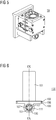
- Glue spreading roller 104 is a part of shaft 105 which includes shaft surface 106 for bearing.
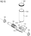
- the bearing is implemented (see FIG 15 ) by bearings 109 (see FIG 6 and FIG 9 ). Sliding bearings or cylinder liners are most advantageously used as bearings 109.
- the surface of glue spreading roller 104 is toothed by, for example, making grooves and/or other suitable surface formations in it, such as protrusions, or their combinations.
- Bearings 109 are set tightly against shaft surface 106 of shaft 105 and thus act as seals.
- the wall strength of bearings 109 is greater than the depth of the area between the adjacent teeth or protrusions of glue spreading roller 104. Bearings 109 are set tightly against the ends of glue spreading roller 104 (in other words, the toothed part of shaft 105) on both sides.
- the outer diameter of bearings 109, the outer diameter of glue spreading roller 104 and the inner surface of base 111 of the glue spreading roller are approximately the same in their diameters in order to get such a compact structure that no glue 901 can escape from glue tank 101 by mistake.
- the dimensioning is such that glue spreading roller 104 is rotatable at the working temperature of the glue.
- the other end of shaft 105 has teeth 107 which, in combination with the grooves left between teeth 107, allow the rotation of shaft 105 by a shape-limited power transmission mechanism.
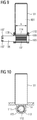
- FIG 10 shows in more detail platform 110 of the glue cartridge, base 111 of the glue spreading roller, lead-thru channel 114, as well as tooth 112 and teeth intervals 113.
- Platform 110 and glue tank 101 can be implemented as a single piece or, as shown in FIG 15 , in two or more separate parts.
- glue cartridge 130 On the edges of glue cartridge 130 are flanges 102 and 103 separated by groove 108.
- Glue cartridge receiving unit 150 has two arms 155.
- glue cartridge receiving unit 150 includes flange 156 on each arm.
- Flange 156 and groove 157 are dimensioned to allow glue cartridge 130 to be slid into receiving unit 150 by inserting flange 156 into groove 108.
- flange 156 and flanges 102, 103 hold glue cartridge 130 in place in receiving unit 150 and prevent glue cartridge 130 from falling.
- Arms 155 are attached to the back support by fastening parts 201, such as bolts, most advantageously through lead-ins 202 made in the back support.
- Glue cartridge 130 can be attached to glue cartridge receiving unit 150 by suitable fastening parts, such as bolts (see FIG 8 ), through holes 801.
- Glue cartridge receiving unit 150 includes a converter which consists of drive mechanism 153 (most advantageously a gear or a sprocket) and shape part 158, which are connected securely to each other via shaft hole 152 in such a way that drive mechanism 153 is accessible from outside of the receiving unit 150.
- drive mechanism 153 most advantageously a gear or a sprocket
- shape part 158 which are connected securely to each other via shaft hole 152 in such a way that drive mechanism 153 is accessible from outside of the receiving unit 150.
- Glue cartridge receiving unit 150 also has thru-holes 154 for attaching heating unit 350 to receiving unit 150.
- FIG 3 presents gluing head 100 to which heating unit 350 has been joined, thus forming ready-for-use gluing head 300.
- Heating unit 350 comprises two halves which are joined to each other by hinges 301.
- Hinges 301 are attached to the halves by attachments such as, for example, impact pins or bolts.
- each half contains heating connector 320 with a first terminal 321 and a second terminal 322. It is also possible to implement heating unit 350 in such a way that there is only one heating connector 320.
- Heating unit 350 includes a resistor between connecting terminals 321, 322. When a voltage is applied across connecting terminals 321, 322 so that current flows through the resistor, heating unit 350 heats to the extent that glue 901 in glue tank 101 melts. Heating unit 350 is preferably made of aluminum.
- Heating unit 350 includes latch locking. Loop 312 is placed over lock pin 313 so that loop 312 comes into groove 314 of lock pin 313. After this lock latch 311 is snapped shut to tighten loop 312 between lock latch 311 and the lock pin.
- Heating unit 350 is ready for use and will heat after the heating connector is connected.
- heat transfer unit 410 can be used.
- the heat transfer unit comprises most advantageously shell 411 and preferably also radial segments 413 separated by walls 412.
- Glue tank 101 can be located off-center with respect to heat transfer unit 410.
- heating unit 350 In designing the thermal power requirement of heating unit 350, it will be sufficient if the center of glue tank 101 is heated up to the working temperature of the used glue 901. Because the diameter e of the cylindrical glue tank 101 is small compared to the dimensions of heat transfer unit 410, it is possible to lead glue from heating unit 350 to glue tank 101 from every direction. Diameter e is as big as, or bigger than, the depth k of lead-thru channel 114.
- the toothed portion of the glue spreading roller 104 has as its length approximately the same as the length of the lead-thru channel 114.
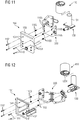
- FIG 11 and 12 show in more detail the attaching of heating unit 350 to glue cartridge receiving unit 150.
- Fastening parts 1101 such as bolts, to be installed preferably in oversized thru-holes 154, are installed in fastening devices 1105 such as threaded bushings.
- compression springs 1103 are installed in connection with fastening parts 1101 between heating unit 350 and glue cartridge receiving unit 150, the attachment can be realised as pre-stressed, in which case it is possible through the spring-loading to get heat exchanger 410 more firmly against the inner surface of heating unit 350 in order to improve heat conduction.
- the diameter of glue tank 101 is so big that heat exchanger 410 is not used, it is possible to get the surface of glue tank 101 (e.g. the cylinder shell in the case presented in FIG 3 ) more firmly against the inner surface of heating unit 350.
- Heat transfer unit 410 can also be installed around glue cartridge 130 in advance, before glue cartridge 130 is installed in the receiving unit.
- FIG 5 presents the thus formed ready-for-use gluing unit 50 after the latch mechanism has been closed.
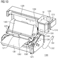
- FIG 13 presents bookbinding device 1300.
- the use of bookbinding device 1300 is started by installing gluing unit 50 below protective cover 1315 and connecting power plug 1391 in cable 1392 to the electricity network. After this, main switch 1375 in control panel 1350 is switched from the OFF position to the ON position. The current flowing in cable 1392 heats the resistance in heating unit 350 and melts glue 901 in glue tank 101.
- Bookbinding device 1300 is equipped with operating lever 1380.
- the principle behind the operation of operating lever 1380 and the operation mechanism of the related bookbinding device is presented in more detail in patent EP 1 478 519 B1 .
- block 1360 is aligned against edge stopper 1340. After this, block 1360 is locked into place by turning lever 1371, in which case movably installed press beam 1370 presses block 1360 against turntable 1390. After this, by further turning lever 1371, press beam 1370 is locked in relation to turntable 1390, whereupon block 1360 also stays in place in relation to turntable 1390.
- lever 1380 is moved in the direction of arrow b.
- turntable 1390 is turned to a position such that the back edge 1362 of block 1360 is on the route of the backwards and forwards-movable (arrow c) gluing head 1310.
- Gluing head 1310 can be moved along slide rail 1320.
- the movement is preferably implemented by using control means 1330 such as a knob.
- the system also has a power transmission means, such as a tooth chain, which rotates drive member 153 most advantageously in a shape-limited way.
- the power transmission means causes drive member 153 to always rotate when gluing head 1310 is pushed in either direction along slide rail 1320.
- drive mechanism 153 While rotating, drive mechanism 153 rotates shape part 158 which, as described above, rotates shaft 105 (shaft 105 and glue spreading roller 104 are in fact most advantageously implemented as a single integral piece), in which case glue spreading roller 104 rotates with it and takes glue from glue tank 101 and spreads it on the back edge 1362 of block 1360.
- glue spreading roller 104 rotates with it and takes glue from glue tank 101 and spreads it on the back edge 1362 of block 1360.
- glue spreading roller 104 is not rotating, the form of glue spreading roller 104 prevents glue from escaping from glue tank 101.
- Bookbinding device 1300 is also equipped with drip tray 1355 in case any glue left at the bottom of glue spreading roller 104 drips or leaks from glue spreading roller 104.
- the ready book is released by moving lever 1371 and it is possible for the bookbinding device to bind the next block of sheets to each other and to a cover.
- the improvement in the bookbinding device 1300 presented in FIG 13 is that glue cartridges 130 can be used in it.
- Glue cartridges 130 are installed for this purpose in gluing unit 50 or alternatively in gluing head 100 or 300. This makes it possible to change the type of glue used on the fly or, at the most, with a small interruption. It is possible to change glue cartridge 130 even when ready-to-be-bound block 1360 is in place in bookbinding device 1300.
- FIG 14a presents the coding included in glue cartridge 130 and glue cartridge receiving unit 150.
- Recess 1400 can be made in bearings casing 110 of glue cartridge 130. The depth of recess 1400 is f.
- pin or bolt 1403 When pin or bolt 1403, pre-stressed by spring 1401, is taken through the back part of glue cartridge receiving unit 150 in such a way that spring 1401 is pressed against the back of pin or bolt 1403 and glue cartridge receiving unit 150 and seeks to push pin or bolt 1403 out, the position of pin or bolt 1403 will depend on depth f, in the case that a glue cartridge 130 has been installed.
- Situation I can correspond with the first type of glue cartridge (e.g. EVA hot melt, one-time use), situation II with the second type (e.g. EVA hot melt, multiple use), situation III with the third type (e.g. PUR glue, one-time use), and situation IV with the fourth type (e.g. PUR glue, multiple use).
- first type of glue cartridge e.g. EVA hot melt, one-time use
- second type e.g. EVA hot melt, multiple use
- situation III e.g. PUR glue, one-time use
- situation IV e.g. PUR glue, multiple use
- FIG 15 presents a modified glue cartridge equipped with detachable cap or cover 1500 instead of fixed cover 200.
- Cover 1500 is screwed securely onto thread 1503.
- Glue tank 101 is screwed from thread 1502 at the bottom to thread 1501 on bearings casing 110.
- glue spreading roller 104 feeds an amount of replacement air into glue tank 101 that corresponds to the glue that glue spreading roller 104 transfers from glue tank 101 to spine 1362 of block 1360 that is to be bound or that otherwise exits from glue spreading roller 104 by dripping, for example.
- the amount of replacement air will correspond with the amount of glue that has been transferred to back edge 1362 of block 1360 or has dripped into drip tray 1355.
- Glue tank 130 can also be manufactured from metalized film (in the same way as bag-in-box wines, in which the wine is in a wine bag), in which case glue 901 can be removed from glue tank 101 without replacement air. This makes a different type of configuration of glue spreading roller 104 possible.
- Glue cartridge 130 can also be heated beforehand (for example, even up to the glue's working temperature or near it, or, on the other hand, for example to halfway between the temperature of the surroundings and the glue's working temperature, or to any point whatsoever between them) at a preheating station located in connection with or outside binding device 1300.
- a preheating station located in connection with or outside binding device 1300.
- a preheating station will have a heating unit corresponding to heating unit 350, and a receiving unit corresponding to receiving unit 150.
- glue cartridge 130 will be more rapidly available and it will be possible to continue the use of binding device 1300 without interruption.
- glue tank 101 of glue cartridge 130 will be heated prior to installing glue cartridge 130 in bookbinding device 1300.
- the heated glue cartridge 130 will then be installed in the binding device, preferably ready-installed in either of gluing heads 100, 300 or in gluing unit 50.
- glue cartridge 130 can be made from aluminum.
- Shaft 105 and glue spreading roller 104 are most advantageously implemented as extruded aluminum profiles. In this case, the extrusion is done using the profile of glue spreading roller 104 and the profile material will be lathed away to form shaft surface 106 (teeth or protrusions away, in addition to which shaft 105 will be thinned with respect to the outside of glue spreading roller 104).
- Gluing unit 50 or gluing head 100, 300 will be removed from bookbinding device 1300 after use. If the part to be removed is hot, the removal can be done using a separate grip or knob.
Landscapes
- Coating Apparatus (AREA)
Claims (14)
- Leimpatrone (130), die folgendes
umfasst:- einen Leimbehälter (101), der im Wesentlichen die Form eines Vorsprungs aus einer Plattform (110) der Leimpatrone aufweist;- eine rotierbare, mit dem Leimbehälter verbundene Walze (104) zum Verteilen des Leims, die direkt unter dem Leimbehälter (101) angeordnet ist; und- mindestens ein Rotationsmittel (105, 106, 107), das von der Außenseite der Leimpatrone (130) aus verwendet werden kann, um die Walze (104) zum Verteilen des Leims zu rotieren;und in dem:die Walze (104) zum Verteilen des Leims so gestaltet ist, dass die Form der Walze (104) zum Verteilen des Leims:mindestens zwei Seiten der Plattform (110) eine Befestigungsvorrichtung (102, 103, 108) aufweisen, um die formschlüssige Befestigung der Leimpatrone (130) an einer Aufnahmeeinheit (150) zu ermöglichen.- verhindert, dass Leim aus dem Leimbehälter (101) austritt, wenn die Walze (104) zum Verteilen des Leims in Position ist und- Leim aus dem Leimbehälter (101) entnimmt, wenn die Walze (104) zum Verteilen des Leims rotiert wird, dadurch gekennzeichnet, dass - Leimpatrone (130) nach Anspruch 1, in dem die Mittel (105, 106, 107) zum Rotieren der Walze (104) zum Verteilen des Leims eine Welle (105) und mindestens ein formschlüssiges Antriebselement (107) umfasst, das an der Welle (105) angeordnet ist.
- Leimpatrone (130) nach Anspruch 1 oder 2, in der der Leimbehälter (101) im Wesentlichen die Form eines Zylinders, eines Konus oder eines stumpfen Konus aufweist.
- Leimpatrone (130) nach einem der vorhergehenden Ansprüche, die zusätzlich eine Kappe oder eine Abdeckung beinhaltet, um die Leimpatrone zu verschließen.
- Leimpatrone (130) nach einem der vorhergehenden Ansprüche, die eine Kodierung aufweist, um den Leimpatronentyp auszudrücken.
- Aufnahmeeinheit (150) für eine Leimpatrone (130) nach einem der Ansprüche 1 bis 5, dadurch gekennzeichnet, dass sie folgendes umfasst:- Mittel (156, 157), zur Aufnahme und Befestigung der Leimpatrone (130) auf eine solche Weise, dass die Walze (104) zum Verteilen des Leims von unten zugänglich ist und daher das Beleimen des Rückens eines zu bindenden Bogenstapels von oben ermöglicht; und- mindestens einen rotierbaren Wandler (153, 240, 152, 158), zur Übertragung von Bewegung auf mindestens ein Rotationsmittel (105, 106, 107) in der Leimpatrone (130).
- Aufnahmeeinheit (150) nach Anspruch 6, die zusätzlich mindestens eine Heizeinheit (350) beinhaltet, um den Leimbehälter (101) aufzuheizen.
- Aufnahmeeinheit (150) nach Anspruch 7, in der die Heizeinheit (350) mindestens eine Einheit (410) zur Wärmeübertragung beinhaltet, die eine Ummantelung (411) und vorzugsweise radiale Segmente (412, 413) umfasst und die am vorteilhaftesten so konfiguriert ist, dass die Leimpatrone in der Heizeinheit nicht zentriert ist.
- Aufnahmeeinheit (300) nach einem der Ansprüche 7 oder 8, in der die Heizeinheit (350) eine klappbare Verschlussvorrichtung (380) umfasst, die so konfiguriert ist, dass die Verschlussvorrichtung das Entfernen mindestens einer Einheit (410) zur Wärmeübertragung und/oder eines Leimbehälters (101) in lateraler Richtung verhindert.
- Aufnahmeeinheit (300) nach einem der Ansprüche 6 - 9, in der die Heizeinheit (350) durch Befestigen zweier identischer Teile aneinander gebildet wird, wodurch dann mindestens eine Einheit (410) zur Wärmeübertragung und/oder ein Leimbehälter (101) in lateraler Richtung arretiert ist.
- Aufnahmeeinheit (300) nach einem der Ansprüche 6 - 10, die Mittel beinhaltet, um die Kodierung in der Leimpatrone (130) auszudrücken.
- Buchbindevorrichtung (1300), in der ein zu bindender Bogenstapel (1360), der ein Buch bilden soll, platziert werden kann und mit dessen Hilfe Leim auf dem Rücken (1362) des Stapels (1360) aufgetragen werden kann, dadurch gekennzeichnet, dass: Leim aus der austauschbaren Leimpatrone (130) nach einem der Ansprüche 1 - 5 entnommen wird, indem die Aufnahmeeinheit (150) nach einem der Ansprüche 6-11 verwendet wird.
- Buchbindevorrichtung (1300) nach Anspruch 12, die eine vorwärts und rückwärts bewegbare Verteileinheit (1310) für den Leim umfasst, die so konfiguriert ist, dass sie die Walze (104) zum Verteilen des Leims der austauschbaren Leimpatrone (130) rotiert, wenn die Verteileinheit (1310) für den Leim vorwärts und rückwärts bewegt wird, wodurch dann der Leim im Leimbehälter (101) auf den Rücken des Stapels (1360) aufgebracht werden kann.
- Buchbindevorrichtung (1300) nach Anspruch 12 oder 13, die konfiguriert ist zur Anpassungi) entweder der Temperatur und/oder der Heizleistung des Leimbehälters (101), oderii) der Temperatur und/oder der Heizenergie der Heizleistung (350), oderiii) der Temperatur und/oder der Heizleistung sowohl des Leimbehälters als auch der Heizeinheitwie in einer Kodierung der Leimpatrone (130) angegeben.
Priority Applications (1)
| Application Number | Priority Date | Filing Date | Title |
|---|---|---|---|
| EP13709560.0A EP2809452B1 (de) | 2012-02-04 | 2013-02-04 | Klebstoffkartusche, aufnahmevorrichtung für klebstoffkartusche und buchbindemaschine |
Applications Claiming Priority (3)
| Application Number | Priority Date | Filing Date | Title |
|---|---|---|---|
| EP12153960.5A EP2623212A1 (de) | 2012-02-04 | 2012-02-04 | Klebstoffkartusche, Aufnahmevorrichtung für Klebstoffkartusche und Buchbindemaschine |
| PCT/IB2013/050927 WO2013114344A1 (en) | 2012-02-04 | 2013-02-04 | A glue cartridge, a glue cartridge receiving unit and a bookbinding device |
| EP13709560.0A EP2809452B1 (de) | 2012-02-04 | 2013-02-04 | Klebstoffkartusche, aufnahmevorrichtung für klebstoffkartusche und buchbindemaschine |
Publications (2)
| Publication Number | Publication Date |
|---|---|
| EP2809452A1 EP2809452A1 (de) | 2014-12-10 |
| EP2809452B1 true EP2809452B1 (de) | 2017-04-12 |
Family
ID=47884446
Family Applications (2)
| Application Number | Title | Priority Date | Filing Date |
|---|---|---|---|
| EP12153960.5A Withdrawn EP2623212A1 (de) | 2012-02-04 | 2012-02-04 | Klebstoffkartusche, Aufnahmevorrichtung für Klebstoffkartusche und Buchbindemaschine |
| EP13709560.0A Active EP2809452B1 (de) | 2012-02-04 | 2013-02-04 | Klebstoffkartusche, aufnahmevorrichtung für klebstoffkartusche und buchbindemaschine |
Family Applications Before (1)
| Application Number | Title | Priority Date | Filing Date |
|---|---|---|---|
| EP12153960.5A Withdrawn EP2623212A1 (de) | 2012-02-04 | 2012-02-04 | Klebstoffkartusche, Aufnahmevorrichtung für Klebstoffkartusche und Buchbindemaschine |
Country Status (4)
| Country | Link |
|---|---|
| US (1) | US9701149B2 (de) |
| EP (2) | EP2623212A1 (de) |
| PL (1) | PL2809452T3 (de) |
| WO (1) | WO2013114344A1 (de) |
Cited By (1)
| Publication number | Priority date | Publication date | Assignee | Title |
|---|---|---|---|---|
| EP4656403A1 (de) | 2024-05-28 | 2025-12-03 | Fastbind Maping Oy | Buchbindemaschine |
Families Citing this family (6)
| Publication number | Priority date | Publication date | Assignee | Title |
|---|---|---|---|---|
| DE102012201655A1 (de) | 2012-02-05 | 2013-08-08 | Maping Kommandiittiyhtiö L. Huotari | Vorrichtung und System zum Entfernen von Klebstoff aus einem Klebstoffbehälter |
| EP2832556B1 (de) | 2013-08-02 | 2016-11-09 | Maping Kommandiittiyhtiö L. Huotari | System zur Verwendung einer auswechselbaren Leimpatrone, und eine Buchbindemaschine |
| CN108787319B (zh) * | 2018-08-17 | 2023-04-25 | 浙江永和纺织植绒有限公司 | 一种植绒上胶机 |
| CN108906501A (zh) * | 2018-10-17 | 2018-11-30 | 华霆(合肥)动力技术有限公司 | 涂胶结构及系统 |
| CN111558499B (zh) * | 2020-06-05 | 2025-03-14 | 广州弘亚数控机械股份有限公司 | 一种涂胶装置 |
| WO2022109689A1 (pt) * | 2020-11-26 | 2022-06-02 | Souza Silvano Baptista De | Aplicador industrial de adesivos termoplásticos |
Family Cites Families (8)
| Publication number | Priority date | Publication date | Assignee | Title |
|---|---|---|---|---|
| FI60991C (fi) * | 1980-05-22 | 1982-05-10 | Maping Ky L Huotari | Anordning foer hopbindning av ark |
| US5221112A (en) * | 1991-12-11 | 1993-06-22 | Holmberg Albert E | Method and apparatus for binding books |
| NL1013927C2 (nl) * | 1999-12-22 | 2001-06-25 | Boekbinderij Letteboer B V | Werkwijze voor het vervaardigen van een boek en boek vervaardigd volgens deze werkwijze. |
| FI119287B (fi) * | 2002-01-29 | 2008-09-30 | Maping Ky L Huotari | Menetelmä ja laite kuumaliimaukseen |
| FI111142B (fi) | 2002-02-06 | 2003-06-13 | Maping Ky L Huotari | Käyttölaite |
| EP1876031B1 (de) * | 2006-07-05 | 2012-02-08 | 4 B - FOUR BIND S.r.l. | Klebstoffauftragvorrichtung für Buchbindemaschinen |
| ITPD20080154A1 (it) * | 2008-05-28 | 2009-11-29 | New Bind Srl | Applicatore di colla per macchine brossuratrici |
| EP2550165A1 (de) * | 2010-03-24 | 2013-01-30 | 4 B - FOUR BIND S.r.l. | Kleberapplikator für buchbindemaschinen |
-
2012
- 2012-02-04 EP EP12153960.5A patent/EP2623212A1/de not_active Withdrawn
-
2013
- 2013-02-04 PL PL13709560T patent/PL2809452T3/pl unknown
- 2013-02-04 US US14/375,635 patent/US9701149B2/en not_active Expired - Fee Related
- 2013-02-04 EP EP13709560.0A patent/EP2809452B1/de active Active
- 2013-02-04 WO PCT/IB2013/050927 patent/WO2013114344A1/en not_active Ceased
Non-Patent Citations (1)
| Title |
|---|
| None * |
Cited By (2)
| Publication number | Priority date | Publication date | Assignee | Title |
|---|---|---|---|---|
| EP4656403A1 (de) | 2024-05-28 | 2025-12-03 | Fastbind Maping Oy | Buchbindemaschine |
| WO2025247993A1 (en) | 2024-05-28 | 2025-12-04 | Fastbind Maping Oy | A bookbinding machine |
Also Published As
| Publication number | Publication date |
|---|---|
| EP2809452A1 (de) | 2014-12-10 |
| PL2809452T3 (pl) | 2017-09-29 |
| WO2013114344A1 (en) | 2013-08-08 |
| US20150023766A1 (en) | 2015-01-22 |
| EP2623212A1 (de) | 2013-08-07 |
| US9701149B2 (en) | 2017-07-11 |
Similar Documents
| Publication | Publication Date | Title |
|---|---|---|
| US9701149B2 (en) | Bookbinding device having a glue cartridge and, a glue cartridge receiving unit | |
| DE69719016T2 (de) | Bürobindereivorrichtung und bindestreifen mit ausrichtemittel | |
| EP2832556B1 (de) | System zur Verwendung einer auswechselbaren Leimpatrone, und eine Buchbindemaschine | |
| CN103660614A (zh) | 打印机 | |
| JP6320579B2 (ja) | アプリケータが組み込まれた加熱式化粧品サンプラー | |
| DE10243704A1 (de) | Etikettiermaschine für die Verarbeitung von mit thermoaktivierbarem Leim beschichteten Einzelblattetiketten | |
| DK2720879T3 (en) | Element for the preparation of a binder or a blackboard and method which makes use of such an element in the manufacture of the binder or billboard | |
| US20040028505A1 (en) | Document tape binding system with automatic tape feed, tape indicia sensing, spine printing method and post-bind automation mechanisms | |
| DE60306446D1 (de) | Thermoaufzeichnungsgerät für ein Thermoaufzeichnungsblatt und Drucker, der dieses Thermoaufzeichnungsgerät verwendet | |
| EP1518706A3 (de) | Schutzschichtübertragungsblatt und Bildaufzeichnungsverfahren mit diesem Blatt | |
| JP5440458B2 (ja) | 冊子製造装置 | |
| JPH02501726A (ja) | サーマルプリンタのレシーバシートクランプ装置 | |
| WO1996033811A9 (en) | Adhesive cartridge for a desktop book binder | |
| WO1996033811A1 (en) | Adhesive cartridge for a desktop book binder | |
| US20070031617A1 (en) | Thermal transfer media with protective patch and adhering receptive layer and method of using the same | |
| CN109291643A (zh) | 麻醉精神处方打印装置 | |
| DE60042303D1 (de) | Mehrfarben Drucker mit einem Umlauf und dessen Druckverfahren | |
| GB0325837D0 (en) | Thermal transfer label printer with rewind control, and method for multiple label printing | |
| US9956808B2 (en) | Automatic circulation binder | |
| WO1991009737A3 (en) | Method and apparatus for fusing thermal transfer prints | |
| CN103625130B (zh) | 自清洁介质穿孔器 | |
| JP2009083358A (ja) | 製本装置 | |
| KR101982666B1 (ko) | 포토 프린터 | |
| DE602006007794D1 (de) | Bilderzeugungsvorrichtung mit Andruckvorrichtung, um die Zuführrolle auf das Aufzeichnungsmedium zu drücken | |
| EP2508456B1 (de) | System zur schnellkopplung von spulen an eine rotationsachse und dessen verwendung für die kopplung einer spule eines thermischen übertragungsbandes an eine druckmaschine |
Legal Events
| Date | Code | Title | Description |
|---|---|---|---|
| PUAI | Public reference made under article 153(3) epc to a published international application that has entered the european phase |
Free format text: ORIGINAL CODE: 0009012 |
|
| 17P | Request for examination filed |
Effective date: 20140711 |
|
| AK | Designated contracting states |
Kind code of ref document: A1 Designated state(s): AL AT BE BG CH CY CZ DE DK EE ES FI FR GB GR HR HU IE IS IT LI LT LU LV MC MK MT NL NO PL PT RO RS SE SI SK SM TR |
|
| AX | Request for extension of the european patent |
Extension state: BA ME |
|
| DAX | Request for extension of the european patent (deleted) | ||
| GRAP | Despatch of communication of intention to grant a patent |
Free format text: ORIGINAL CODE: EPIDOSNIGR1 |
|
| INTG | Intention to grant announced |
Effective date: 20160922 |
|
| GRAS | Grant fee paid |
Free format text: ORIGINAL CODE: EPIDOSNIGR3 |
|
| GRAA | (expected) grant |
Free format text: ORIGINAL CODE: 0009210 |
|
| AK | Designated contracting states |
Kind code of ref document: B1 Designated state(s): AL AT BE BG CH CY CZ DE DK EE ES FI FR GB GR HR HU IE IS IT LI LT LU LV MC MK MT NL NO PL PT RO RS SE SI SK SM TR |
|
| REG | Reference to a national code |
Ref country code: GB Ref legal event code: FG4D |
|
| REG | Reference to a national code |
Ref country code: CH Ref legal event code: EP |
|
| REG | Reference to a national code |
Ref country code: IE Ref legal event code: FG4D |
|
| REG | Reference to a national code |
Ref country code: AT Ref legal event code: REF Ref document number: 883325 Country of ref document: AT Kind code of ref document: T Effective date: 20170515 |
|
| REG | Reference to a national code |
Ref country code: DE Ref legal event code: R096 Ref document number: 602013019720 Country of ref document: DE |
|
| REG | Reference to a national code |
Ref country code: NL Ref legal event code: FP |
|
| REG | Reference to a national code |
Ref country code: LT Ref legal event code: MG4D |
|
| REG | Reference to a national code |
Ref country code: AT Ref legal event code: MK05 Ref document number: 883325 Country of ref document: AT Kind code of ref document: T Effective date: 20170412 |
|
| PG25 | Lapsed in a contracting state [announced via postgrant information from national office to epo] |
Ref country code: AT Free format text: LAPSE BECAUSE OF FAILURE TO SUBMIT A TRANSLATION OF THE DESCRIPTION OR TO PAY THE FEE WITHIN THE PRESCRIBED TIME-LIMIT Effective date: 20170412 Ref country code: NO Free format text: LAPSE BECAUSE OF FAILURE TO SUBMIT A TRANSLATION OF THE DESCRIPTION OR TO PAY THE FEE WITHIN THE PRESCRIBED TIME-LIMIT Effective date: 20170712 Ref country code: HR Free format text: LAPSE BECAUSE OF FAILURE TO SUBMIT A TRANSLATION OF THE DESCRIPTION OR TO PAY THE FEE WITHIN THE PRESCRIBED TIME-LIMIT Effective date: 20170412 Ref country code: ES Free format text: LAPSE BECAUSE OF FAILURE TO SUBMIT A TRANSLATION OF THE DESCRIPTION OR TO PAY THE FEE WITHIN THE PRESCRIBED TIME-LIMIT Effective date: 20170412 Ref country code: GR Free format text: LAPSE BECAUSE OF FAILURE TO SUBMIT A TRANSLATION OF THE DESCRIPTION OR TO PAY THE FEE WITHIN THE PRESCRIBED TIME-LIMIT Effective date: 20170713 Ref country code: LT Free format text: LAPSE BECAUSE OF FAILURE TO SUBMIT A TRANSLATION OF THE DESCRIPTION OR TO PAY THE FEE WITHIN THE PRESCRIBED TIME-LIMIT Effective date: 20170412 Ref country code: FI Free format text: LAPSE BECAUSE OF FAILURE TO SUBMIT A TRANSLATION OF THE DESCRIPTION OR TO PAY THE FEE WITHIN THE PRESCRIBED TIME-LIMIT Effective date: 20170412 |
|
| PG25 | Lapsed in a contracting state [announced via postgrant information from national office to epo] |
Ref country code: BG Free format text: LAPSE BECAUSE OF FAILURE TO SUBMIT A TRANSLATION OF THE DESCRIPTION OR TO PAY THE FEE WITHIN THE PRESCRIBED TIME-LIMIT Effective date: 20170712 Ref country code: RS Free format text: LAPSE BECAUSE OF FAILURE TO SUBMIT A TRANSLATION OF THE DESCRIPTION OR TO PAY THE FEE WITHIN THE PRESCRIBED TIME-LIMIT Effective date: 20170412 Ref country code: SE Free format text: LAPSE BECAUSE OF FAILURE TO SUBMIT A TRANSLATION OF THE DESCRIPTION OR TO PAY THE FEE WITHIN THE PRESCRIBED TIME-LIMIT Effective date: 20170412 Ref country code: IS Free format text: LAPSE BECAUSE OF FAILURE TO SUBMIT A TRANSLATION OF THE DESCRIPTION OR TO PAY THE FEE WITHIN THE PRESCRIBED TIME-LIMIT Effective date: 20170812 Ref country code: LV Free format text: LAPSE BECAUSE OF FAILURE TO SUBMIT A TRANSLATION OF THE DESCRIPTION OR TO PAY THE FEE WITHIN THE PRESCRIBED TIME-LIMIT Effective date: 20170412 |
|
| REG | Reference to a national code |
Ref country code: DE Ref legal event code: R097 Ref document number: 602013019720 Country of ref document: DE |
|
| PG25 | Lapsed in a contracting state [announced via postgrant information from national office to epo] |
Ref country code: CZ Free format text: LAPSE BECAUSE OF FAILURE TO SUBMIT A TRANSLATION OF THE DESCRIPTION OR TO PAY THE FEE WITHIN THE PRESCRIBED TIME-LIMIT Effective date: 20170412 Ref country code: RO Free format text: LAPSE BECAUSE OF FAILURE TO SUBMIT A TRANSLATION OF THE DESCRIPTION OR TO PAY THE FEE WITHIN THE PRESCRIBED TIME-LIMIT Effective date: 20170412 Ref country code: DK Free format text: LAPSE BECAUSE OF FAILURE TO SUBMIT A TRANSLATION OF THE DESCRIPTION OR TO PAY THE FEE WITHIN THE PRESCRIBED TIME-LIMIT Effective date: 20170412 Ref country code: EE Free format text: LAPSE BECAUSE OF FAILURE TO SUBMIT A TRANSLATION OF THE DESCRIPTION OR TO PAY THE FEE WITHIN THE PRESCRIBED TIME-LIMIT Effective date: 20170412 Ref country code: SK Free format text: LAPSE BECAUSE OF FAILURE TO SUBMIT A TRANSLATION OF THE DESCRIPTION OR TO PAY THE FEE WITHIN THE PRESCRIBED TIME-LIMIT Effective date: 20170412 |
|
| PLBE | No opposition filed within time limit |
Free format text: ORIGINAL CODE: 0009261 |
|
| STAA | Information on the status of an ep patent application or granted ep patent |
Free format text: STATUS: NO OPPOSITION FILED WITHIN TIME LIMIT |
|
| REG | Reference to a national code |
Ref country code: FR Ref legal event code: PLFP Year of fee payment: 6 |
|
| PG25 | Lapsed in a contracting state [announced via postgrant information from national office to epo] |
Ref country code: SM Free format text: LAPSE BECAUSE OF FAILURE TO SUBMIT A TRANSLATION OF THE DESCRIPTION OR TO PAY THE FEE WITHIN THE PRESCRIBED TIME-LIMIT Effective date: 20170412 |
|
| 26N | No opposition filed |
Effective date: 20180115 |
|
| PG25 | Lapsed in a contracting state [announced via postgrant information from national office to epo] |
Ref country code: SI Free format text: LAPSE BECAUSE OF FAILURE TO SUBMIT A TRANSLATION OF THE DESCRIPTION OR TO PAY THE FEE WITHIN THE PRESCRIBED TIME-LIMIT Effective date: 20170412 |
|
| REG | Reference to a national code |
Ref country code: CH Ref legal event code: PL |
|
| PG25 | Lapsed in a contracting state [announced via postgrant information from national office to epo] |
Ref country code: MC Free format text: LAPSE BECAUSE OF FAILURE TO SUBMIT A TRANSLATION OF THE DESCRIPTION OR TO PAY THE FEE WITHIN THE PRESCRIBED TIME-LIMIT Effective date: 20170412 |
|
| REG | Reference to a national code |
Ref country code: IE Ref legal event code: MM4A |
|
| REG | Reference to a national code |
Ref country code: BE Ref legal event code: MM Effective date: 20180228 |
|
| PG25 | Lapsed in a contracting state [announced via postgrant information from national office to epo] |
Ref country code: CH Free format text: LAPSE BECAUSE OF NON-PAYMENT OF DUE FEES Effective date: 20180228 Ref country code: LU Free format text: LAPSE BECAUSE OF NON-PAYMENT OF DUE FEES Effective date: 20180204 Ref country code: LI Free format text: LAPSE BECAUSE OF NON-PAYMENT OF DUE FEES Effective date: 20180228 |
|
| PG25 | Lapsed in a contracting state [announced via postgrant information from national office to epo] |
Ref country code: IE Free format text: LAPSE BECAUSE OF NON-PAYMENT OF DUE FEES Effective date: 20180204 |
|
| PG25 | Lapsed in a contracting state [announced via postgrant information from national office to epo] |
Ref country code: BE Free format text: LAPSE BECAUSE OF NON-PAYMENT OF DUE FEES Effective date: 20180228 |
|
| PG25 | Lapsed in a contracting state [announced via postgrant information from national office to epo] |
Ref country code: MT Free format text: LAPSE BECAUSE OF NON-PAYMENT OF DUE FEES Effective date: 20180204 |
|
| PG25 | Lapsed in a contracting state [announced via postgrant information from national office to epo] |
Ref country code: TR Free format text: LAPSE BECAUSE OF FAILURE TO SUBMIT A TRANSLATION OF THE DESCRIPTION OR TO PAY THE FEE WITHIN THE PRESCRIBED TIME-LIMIT Effective date: 20170412 |
|
| PGFP | Annual fee paid to national office [announced via postgrant information from national office to epo] |
Ref country code: PL Payment date: 20200203 Year of fee payment: 8 Ref country code: NL Payment date: 20200219 Year of fee payment: 8 |
|
| PG25 | Lapsed in a contracting state [announced via postgrant information from national office to epo] |
Ref country code: HU Free format text: LAPSE BECAUSE OF FAILURE TO SUBMIT A TRANSLATION OF THE DESCRIPTION OR TO PAY THE FEE WITHIN THE PRESCRIBED TIME-LIMIT; INVALID AB INITIO Effective date: 20130204 Ref country code: PT Free format text: LAPSE BECAUSE OF FAILURE TO SUBMIT A TRANSLATION OF THE DESCRIPTION OR TO PAY THE FEE WITHIN THE PRESCRIBED TIME-LIMIT Effective date: 20170412 |
|
| PG25 | Lapsed in a contracting state [announced via postgrant information from national office to epo] |
Ref country code: MK Free format text: LAPSE BECAUSE OF NON-PAYMENT OF DUE FEES Effective date: 20170412 Ref country code: CY Free format text: LAPSE BECAUSE OF FAILURE TO SUBMIT A TRANSLATION OF THE DESCRIPTION OR TO PAY THE FEE WITHIN THE PRESCRIBED TIME-LIMIT Effective date: 20170412 |
|
| PG25 | Lapsed in a contracting state [announced via postgrant information from national office to epo] |
Ref country code: AL Free format text: LAPSE BECAUSE OF FAILURE TO SUBMIT A TRANSLATION OF THE DESCRIPTION OR TO PAY THE FEE WITHIN THE PRESCRIBED TIME-LIMIT Effective date: 20170412 |
|
| REG | Reference to a national code |
Ref country code: NL Ref legal event code: MM Effective date: 20210301 |
|
| PG25 | Lapsed in a contracting state [announced via postgrant information from national office to epo] |
Ref country code: NL Free format text: LAPSE BECAUSE OF NON-PAYMENT OF DUE FEES Effective date: 20210301 |
|
| PG25 | Lapsed in a contracting state [announced via postgrant information from national office to epo] |
Ref country code: PL Free format text: LAPSE BECAUSE OF NON-PAYMENT OF DUE FEES Effective date: 20210204 |
|
| PGFP | Annual fee paid to national office [announced via postgrant information from national office to epo] |
Ref country code: GB Payment date: 20260218 Year of fee payment: 14 |
|
| PGFP | Annual fee paid to national office [announced via postgrant information from national office to epo] |
Ref country code: DE Payment date: 20260217 Year of fee payment: 14 |
|
| PGFP | Annual fee paid to national office [announced via postgrant information from national office to epo] |
Ref country code: IT Payment date: 20260219 Year of fee payment: 14 |
|
| PGFP | Annual fee paid to national office [announced via postgrant information from national office to epo] |
Ref country code: FR Payment date: 20260218 Year of fee payment: 14 |