EP2808992A2 - Motor control device - Google Patents
Motor control device Download PDFInfo
- Publication number
- EP2808992A2 EP2808992A2 EP14170490.8A EP14170490A EP2808992A2 EP 2808992 A2 EP2808992 A2 EP 2808992A2 EP 14170490 A EP14170490 A EP 14170490A EP 2808992 A2 EP2808992 A2 EP 2808992A2
- Authority
- EP
- European Patent Office
- Prior art keywords
- speed
- motor
- unit
- control device
- gain
- Prior art date
- Legal status (The legal status is an assumption and is not a legal conclusion. Google has not performed a legal analysis and makes no representation as to the accuracy of the status listed.)
- Granted
Links
Images

Classifications
-
- H—ELECTRICITY
- H02—GENERATION; CONVERSION OR DISTRIBUTION OF ELECTRIC POWER
- H02P—CONTROL OR REGULATION OF ELECTRIC MOTORS, ELECTRIC GENERATORS OR DYNAMO-ELECTRIC CONVERTERS; CONTROLLING TRANSFORMERS, REACTORS OR CHOKE COILS
- H02P7/00—Arrangements for regulating or controlling the speed or torque of electric DC motors
- H02P7/06—Arrangements for regulating or controlling the speed or torque of electric DC motors for regulating or controlling an individual DC dynamo-electric motor by varying field or armature current
- H02P7/18—Arrangements for regulating or controlling the speed or torque of electric DC motors for regulating or controlling an individual DC dynamo-electric motor by varying field or armature current by master control with auxiliary power
- H02P7/24—Arrangements for regulating or controlling the speed or torque of electric DC motors for regulating or controlling an individual DC dynamo-electric motor by varying field or armature current by master control with auxiliary power using discharge tubes or semiconductor devices
- H02P7/28—Arrangements for regulating or controlling the speed or torque of electric DC motors for regulating or controlling an individual DC dynamo-electric motor by varying field or armature current by master control with auxiliary power using discharge tubes or semiconductor devices using semiconductor devices
-
- G—PHYSICS
- G03—PHOTOGRAPHY; CINEMATOGRAPHY; ANALOGOUS TECHNIQUES USING WAVES OTHER THAN OPTICAL WAVES; ELECTROGRAPHY; HOLOGRAPHY
- G03G—ELECTROGRAPHY; ELECTROPHOTOGRAPHY; MAGNETOGRAPHY
- G03G15/00—Apparatus for electrographic processes using a charge pattern
- G03G15/50—Machine control of apparatus for electrographic processes using a charge pattern, e.g. regulating differents parts of the machine, multimode copiers, microprocessor control
- G03G15/5008—Driving control for rotary photosensitive medium, e.g. speed control, stop position control
-
- H—ELECTRICITY
- H02—GENERATION; CONVERSION OR DISTRIBUTION OF ELECTRIC POWER
- H02P—CONTROL OR REGULATION OF ELECTRIC MOTORS, ELECTRIC GENERATORS OR DYNAMO-ELECTRIC CONVERTERS; CONTROLLING TRANSFORMERS, REACTORS OR CHOKE COILS
- H02P23/00—Arrangements or methods for the control of AC motors characterised by a control method other than vector control
- H02P23/0004—Control strategies in general, e.g. linear type, e.g. P, PI, PID, using robust control
-
- H—ELECTRICITY
- H02—GENERATION; CONVERSION OR DISTRIBUTION OF ELECTRIC POWER
- H02P—CONTROL OR REGULATION OF ELECTRIC MOTORS, ELECTRIC GENERATORS OR DYNAMO-ELECTRIC CONVERTERS; CONTROLLING TRANSFORMERS, REACTORS OR CHOKE COILS
- H02P6/00—Arrangements for controlling synchronous motors or other dynamo-electric motors using electronic commutation dependent on the rotor position; Electronic commutators therefor
- H02P6/14—Electronic commutators
- H02P6/16—Circuit arrangements for detecting position
Definitions
- the motor control device of the second embodiment is provided with the error amplification unit 13 that has proportional integral characteristics by which integration is performed in a lower frequency range than a given integral corner frequency. As the current rotation speed of the brushless DC motor 3 is higher, the error amplification unit 13 increases a proportional gain and shifts the integral corner frequency to a lower frequency.
- the motor control device of the second embodiment is provided with an error amplification unit that has proportional differential characteristics by which differentiation is performed in a higher frequency range than a given differential corner frequency, in addition to the proportional integral characteristics.
- FIG. 8 illustrates a block diagram of an error amplification unit 40 provided in a motor control device of the second embodiment.
- the error amplification unit 40 illustrated in FIG. 8 the parts performing the same actions as in the error amplification unit 13 illustrated in FIG. 2 are denoted by the same symbols.
- the error amplification unit 40 provided in the motor control device of the second embodiment has a configuration further including an amplification unit 41, a multiplication unit 42, and a differentiation unit 43, in addition to the components of the error amplification unit 13.
- the error amplification unit 50 includes a reciprocal unit 51 that generates a corner frequency variable amount Fadj using a gain variable amount Gadj supplied from the G/F control unit 15 through the input terminal 28 and supplies the corner frequency variable amount Fadj to the multiplication unit 24 and the multiplication unit 42.
Landscapes
- Engineering & Computer Science (AREA)
- Power Engineering (AREA)
- Microelectronics & Electronic Packaging (AREA)
- Physics & Mathematics (AREA)
- General Physics & Mathematics (AREA)
- Control Of Electric Motors In General (AREA)
- Control Of Motors That Do Not Use Commutators (AREA)
- Control Of Direct Current Motors (AREA)
Abstract
Description
- The present application claims priority to and incorporates by reference the entire contents of Japanese Patent Application No.
2013-114496 - The present invention relates to a motor control device.
- There is known a direct current (DC) motor that rotates at a rotation speed proportional to an applied voltage. As a kind of such a DC motor, there are known a brush motor and a brushless motor. The brushless motor is free from brush wear and has high durability, and is thus used frequently. Under feedback control using a position/speed sensor of an encoder, and other components, the DC motors are controlled to stop (speed zero) at arbitrary timing or controlled to an arbitrary target speed.
- Japanese Laid-open Patent Publication No.
2009-148082 - However, the response characteristics (change of a revolving speed in accordance with an applied voltage) of the DC motors such as a brushless motor change significantly depending on a rotation speed. When the rotation speed is changed, the total feedback characteristics are also changed. Thus, when the rotation speed is controlled using a fixed feedback gain, for example, it is difficult to stably control a rotation speed in a wide range.
- Moreover, in the case of the image forming apparatus disclosed in Japanese Laid-open Patent Publication No.
2009-148082 - In view of the above, there is a need to provide a motor control device capable of controlling a rotation speed of a motor stably and optimally.
- It is an object of the present invention to at least partially solve the problems in the conventional technology.
- A motor control device controls a speed of a motor. The motor control device includes: a target speed generating unit that generates a target speed; a speed detecting unit that detects a current speed of the motor; a speed comparing unit that compares the target speed with the current speed to calculate a speed error; an error amplifying unit that amplifies the speed error and outputs a control value; and a motor driving unit that drives the motor in accordance with the control value. The error amplifying unit has proportional integral characteristics by which the speed error is amplified with a proportional gain and integral is performed in a lower frequency range than an integral corner frequency, increases the proportional gain as the current speed is higher, and shifts the integral corner frequency to a lower frequency as the current speed is higher.
- The above and other objects, features, advantages and technical and industrial significance of this invention will be better understood by reading the following detailed description of presently preferred embodiments of the invention, when considered in connection with the accompanying drawings.
-
-
FIG. 1 is a block diagram illustrating a motor control device of a first embodiment; -
FIG. 2 is a block diagram illustrating an error amplification unit provided in the motor control device of the first embodiment; -
FIG. 3 is a block diagram illustrating a gain/corner frequency control unit (G/F control unit) provided in the motor control device of the first embodiment; -
FIG. 4 is a graph illustrating the relation between a gain variable amount generated by the G/F control unit and a rotation speed of the brushless DC motor; -
FIG. 5 is a graph illustrating the relation between step response and a mechanical time constant of the brushless DC motor; -
FIG. 6 is a graph illustrating plotted mechanical time constants with different initial rotation speeds of the brushless DC motor; -
FIG. 7 is a Bode diagram illustrating frequency characteristics when the error amplification unit is controlled using a gain variable amount and a corner frequency variable amount from the G/F control unit; -
FIG. 8 is a block diagram illustrating an error amplification unit provided in a motor control device of a second embodiment; -
FIG. 9 is a block diagram illustrating an error amplification unit provided in a motor control device of a third embodiment; -
FIG. 10 is a block diagram illustrating an error amplification unit provided in a motor control device of a fourth embodiment; -
FIG. 11 is a graph illustrating the relation between a gain variable amount generated by a G/F control unit provided in a motor control device of a fifth embodiment and a rotation speed of a brushless DC motor; and -
FIG. 12 is a block diagram illustrating a motor control device of a sixth embodiment. - The following describes the embodiments of the motor control device in detail with reference to the enclosed drawings.
-
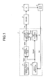
FIG. 1 is a block diagram illustrating a motor control device of the first embodiment. As illustrated inFIG. 1 , the motor control device of the first embodiment includes acontroller 1, adriver 2, a brushless DC motor (M) 3, and asensor 4. Thecontroller 1 includes a targetspeed generation unit 11, aspeed comparison unit 12, anerror amplification unit 13, aspeed detector 14, and a gain/corner frequency control unit (G/F control unit) 15. The targetspeed generation unit 11 is an example of a target speed generating unit. Thespeed detector 14 is an example of a speed detecting unit. Thespeed comparison unit 12 is an example of a speed comparing unit. Theerror amplification unit 13 is an example of an error amplifying unit. Thedriver 2 is an example of a motor driving unit. - The target
speed generation unit 11 outputs a certain target value (target speed TgtSp) corresponding to a motor speed used in the motor control device of the first embodiment. To be more specific, the target speed TgtSp may be constant. In the case of a position determination system that moves thebrushless DC motor 3 by a certain distance, the target speed TgtSp changing continuously from zero to a given speed is used. Furthermore, the target speed TgtSp may be generated in accordance with the result of comparison between a target position and the current position of thebrushless DC motor 3. As mentioned above, various kinds of targetspeed generation unit 11 can be used. In the embodiment, a certain target speed TgtSp is generated. - The
speed detector 14 detects the current speed of thebrushless DC motor 3 and outputs a speed value Speed. The motor speed is measured by thesensor 4 attached to thebrushless DC motor 3 or a component driven by thebrushless DC motor 3. Thespeed comparison unit 12 compares the target speed TgtSp with the current speed value Speed and outputs the difference as a speed error signal SpErr. Theerror amplification unit 13 has a gain and includes an integration unit providing integral characteristics at least at a given frequency or lower. Theerror amplification unit 13 amplifies the speed error signal SpErr, and generates and outputs a control value Drv corresponding to a drive voltage of thebrushless DC motor 3. The detail will be described later. - The G/
F control unit 15 variably controls a proportional gain and a corner frequency of theerror amplification unit 13. That is, the G/F control unit 15 outputs, in accordance with the current speed value Speed, a gain variable amount Gadj for variably controlling a proportional gain in theerror amplification unit 13, and a corner frequency variable amount Fadj for variably controlling a frequency (corner frequency) that is a base point of integral or differential characteristics. The detail will be described later. - The
driver 2 is what is called a motor drive circuit. Thedriver 2 rotationally drives thebrushless DC motor 3 through an electromagnetic coil with a motor drive voltage proportional to a control value Drv from theerror amplification unit 13. Thus, thebrushless DC motor 3 rotates at a speed proportional to the control value Drv. The rotation speed of thebrushless DC motor 3 fluctuates due to a load (not illustrated) or other factors. Usually, in order to correct fluctuation of the rotation speed, the current rotation speed of thebrushless DC motor 3 is fed back to thecontroller 1 to perform control so that the rotation speed of thebrushless DC motor 3 is constant. - The
sensor 4 is a position sensor or a speed sensor. Thesensor 4 detects a rotation position or a rotation speed of thebrushless DC motor 3 and outputs a sensor signal Sns. As thesensor 4, a component that outputs pulse or angle information in accordance with a motor rotation angle, such as an encoder and a resolver, can be used. - Depending on an output form of the
sensor 4, thespeed detector 14 of various configurations can be used. For example, when thesensor 4 outputs a speed signal, thespeed detector 14 converting a speed signal into a value Speed can be used. When thesensor 4 outputs position information, thespeed detector 14 converting position information into speed information by differentiation, for example, can be used. When thesensor 4 outputs pulses of a frequency proportional to a speed, it is possible to use thespeed detector 14 counting the pulse period or the number of pulses and detecting a rotation speed of thebrushless DC motor 3 based on temporal variation of the pulses. -
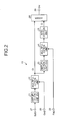
FIG. 2 is a block diagram illustrating theerror amplification unit 13. Theerror amplification unit 13 includes anamplification unit 21, amultiplication unit 22, anamplification unit 23, amultiplication unit 24, anintegration unit 25, and anadder 26. Theamplification unit 21 is a gain factor, and amplifies a speed error signal SpErr with a fixed amplification factor G, the speed error signal SpErr being supplied through aninput terminal 27. Themultiplication unit 22 is a gain variable factor, and generates a control value Ct by multiplying the speed error signal SpErr amplified with the fixed amplification factor G by the gain variable amount Gadj supplied through aninput terminal 28 and outputs the control value Ct. That is, "control value Ct = speed error signal SpErr × fixed amplification factor G × gain variable amount Gadj" is established. - The
amplification unit 23 is a gain factor, and amplifies the control value Ct with a fixed amplification factor Gi. Themultiplication unit 24 is a gain variable factor, and multiplies the control value Ct amplified with the fixed amplification factor Gi by a corner frequency variable amount Fadj supplied through aninput terminal 29. Theintegration unit 25 integrates the control value Ct multiplied by the corner frequency variable amount Fadj to output a control value Ci. Theadder 26 adds the control value Ct from themultiplication unit 22 and the control value Ci from theintegration unit 25 to generate a control value Drv. The control value Drv is supplied to thedriver 2 through anoutput terminal 30. -
FIG. 3 illustrates a block diagram of the G/F control unit 15. The G/F control unit 15 includes again calculation unit 31 and a reciprocal unit 32. Thegain calculation unit 31 outputs a gain variable amount Gadj calculated using a speed value Speed of the current rotation of thebrushless DC motor 3, a coefficient A that is a value of an inclination coefficient, and a coefficient B that is a value of an intercept. That is, thegain calculation unit 31 calculates and outputs a gain variable amount Gadj using the expression "gain variable amount Gadj = coefficient A × speed value Speed + coefficient B". - The reciprocal unit 32 outputs a reciprocal of a gain variable amount Gadj as a corner frequency variable amount Fadj. That is, the reciprocal unit 32 calculates a corner frequency variable amount Fadj using the expression "corner frequency variable amount Fadj = 1/gain variable amount Gadj" and outputs it. The motor control device of the embodiment determines the coefficient A and the coefficient B in accordance with the motor characteristics. Thus, variations of control performance and stability due to motor characteristics can be cancelled, which enables stable and optimum rotation control of the
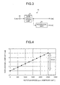
brushless DC motor 3. - As an example,
FIG. 4 is a graph illustrating the relation between the gain variable amount Gadj generated by the G/F control unit 15 and the rotation speed of thebrushless DC motor 3. The scale of the rotation speed, which is indicated by a horizontal axis of the graph inFIG. 4 , is arbitrary, and is revolutions per minute (rpm), for example. The coefficient A and the coefficient B are determined reflecting a variation amount of a later-described mechanical time constant Tm of thebrushless DC motor 3 depending on a rotation speed. For example, in the case of thebrushless DC motor 3 in which the mechanical time constant when the rotation speed is 2500 rpm is five times as much as the mechanical time constant when the rotation is stopped, "coefficient A = 5/2500" and "coefficient B = 1" are established. - The graph in
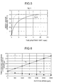
FIG. 5 illustrates the relation between step response and the mechanical time constant Tm of thebrushless DC motor 3. The step response is indicated by plotting motor speeds changing due to stepwise change in an input voltage Vc of thebrushless DC motor 3. The horizontal axis of the graph inFIG. 5 is a time axis. The scale of the horizontal axis is arbitrary, and is millisecond, for example. The vertical axis of the graph inFIG. 5 is a motor speed obtained by normalizing a motor speed variation amount between before and after step voltage application to "1". The time at which the normalized speed change amount reaches 0.63 is "mechanical time constant Tm". - The dotted line graph in
FIG. 5 is obtained by plotting motor speeds when the initial rotation speed is low, and the mechanical time constant Tm in this time is Tm = 1. The solid line graph inFIG. 5 is obtained by plotting motor speeds when the initial rotation speed is high, and the mechanical time constant Tm in this time is Tm = 4. According toFIG. 5 , in thebrushless DC motor 3, the mechanical time constant Tm is larger (= slower in response) as the initial rotation speed (rotation speed before step voltage application) is higher. -
FIG. 6 is a graph illustrating plotted mechanical time constants Tm with different initial rotation speeds of thebrushless DC motor 3. In the graph inFIG. 6 , the mechanical time constant Tm when the motor stops is normalized to one. As can be seen from the graph ofFIG. 6 , the mechanical time constant Tm increases linearly with respect to the rotation speed of thebrushless DC motor 3. The inclination of the straight line is different depending on a model (kind) of the motor. Thus, it is preferable to perform such plotting for each model of motors to obtain basic data. The inclination of the straight line of the gain variable amount Gadj is determined depending on a change rate of the mechanical time constant Tm with respect to the rotation speed of thebrushless DC motor 3. - The coefficient A and the coefficient B can be obtained based on the basic data illustrated in the graph of
FIG. 6 and the variable expression of the gain variable amount Gadj illustrated inFIG. 4 (gain variable amount Gadj = coefficient A × speed value Speed + coefficient B). The G/F control unit is configured using this. -
FIG. 7 illustrates a frequency characteristic Bode diagram when theerror amplification unit 13 is controlled using a gain variable amount Gadj and a break frequency variable amount Fadj from the G/F control unit 15. The Bode diagram is obtained by plotting gains from input to output with a frequency as a horizontal axis. The frequency is indicated with a logarithmic scale, and the gain is indicated with dB (logarithmic value of gain × 20). The use of the logarithmic scale allows approximation of gains with a substantially straight line. The frequency at which a straight line is bent is referred to as a corner frequency. - As can be seen from
FIG. 7 , theerror amplification unit 13 has integral characteristics by which the gain increases in a lower frequency range than an integral corner frequency (integral corner) and, in a higher frequency range than an integral corner frequency, the gain is flat. InFIG. 7 , the Bode diagram when the rotation speed of thebrushless DC motor 3 is low (at a low speed) is illustrated with a bold solid line. When the rotation speed of thebrushless DC motor 3 is higher (at a high speed), the gain variable amount Gadj is increased, and the corner frequency variable amount Fadj is decreased. Thus, at a high speed, the gain in a flat portion is increased and the integral corner frequency is decreased, as illustrated in the Bode diagram of dotted line inFIG. 7 . - The gain is only increased over all only by increasing the gain variable amount Gadj, as illustrated in the Bode diagram of a fine line in
FIG. 7 . This cannot compensate a change of the mechanical time constant Tm. Thus, the G/F control unit 15 supplies a corner frequency variable amount Fadj to theerror amplification unit 13 so as to decrease the integral corner frequency. In this manner, theerror amplification unit 13 obtains characteristics corresponding to a rotation speed, whereby the rotation speed dependency of a motor time constant can be cancelled , which enables stable and optimal rotation control in accordance with a rotation speed. - As is clear from the above description, in the motor control device of the first embodiment, the
error amplification unit 13 has proportional integral characteristics by which the speed error signal SpErr is amplified with a given proportional gain (gain variable amount Gadj) and integration is performed in the lower frequency range than a given integral corner frequency. The G/F control unit 15 controls theerror amplification unit 13 to increase a proportional gain (gain variable amount Gadj) and shift the integral corner frequency to a lower frequency as the current rotation speed of thebrushless DC motor 3 is higher. In this manner, even when the mechanical response characteristics of thebrushless DC motor 3 change depending on a rotation speed, it is possible to perform stable and optimal rotation control of thebrushless DC motor 3 without any influence on following control characteristics. - The following describes the motor control device of the second embodiment. The motor control device of the above-described first embodiment is provided with the
error amplification unit 13 that has proportional integral characteristics by which integration is performed in a lower frequency range than a given integral corner frequency. As the current rotation speed of thebrushless DC motor 3 is higher, theerror amplification unit 13 increases a proportional gain and shifts the integral corner frequency to a lower frequency. By contrast, the motor control device of the second embodiment is provided with an error amplification unit that has proportional differential characteristics by which differentiation is performed in a higher frequency range than a given differential corner frequency, in addition to the proportional integral characteristics. As the current rotation speed of thebrushless DC motor 3 is higher, the error amplification unit increases a proportional gain and shifts the differential corner frequency to a higher frequency. Note that the first embodiment is different from the second embodiment only in this aspect. Therefore, in the following, only the difference between both embodiments is described, and the overlapped description is omitted. -
FIG. 8 illustrates a block diagram of anerror amplification unit 40 provided in a motor control device of the second embodiment. In theerror amplification unit 40 illustrated inFIG. 8 , the parts performing the same actions as in theerror amplification unit 13 illustrated inFIG. 2 are denoted by the same symbols. As can be seen from comparison betweenFIG. 2 andFIG. 8 , theerror amplification unit 40 provided in the motor control device of the second embodiment has a configuration further including anamplification unit 41, amultiplication unit 42, and adifferentiation unit 43, in addition to the components of theerror amplification unit 13. - The
amplification unit 41 is a gain factor, and amplifies the control value Ct from themultiplication unit 22 with a fixed amplification factor Gd. Themultiplication unit 42 is a gain variable factor, and multiplies the control value Ct amplified with the amplification factor Gd by a corner frequency variable amount Fadj supplied from the G/F control unit 15 through theinput terminal 29. Thedifferentiation unit 43 differentiates the control value Ct amplified with the amplification factor Gd and multiplied by the corner frequency variable amount Fadj, and generates a control value Cd. Theadder 26 adds the control value Ct from themultiplication unit 22, the control value Ci generated by integration processing, and the control value Cd generated by differentiation processing, and outputs a control value Drv through theoutput terminal 30. - Such an
error amplification unit 40 has proportional differential characteristics by which differentiation is performed in a higher frequency range than a given differential corner frequency, in addition to the proportional integral characteristics described in the first embodiment. That is, theerror amplification unit 40 has integral characteristics by which the gain increases in a lower frequency range than an integral corner frequency and differential characteristics by which the gain increases in a higher frequency range than a differential corner frequency, as illustrated in the Bode diagram ofFIG. 7 . The gain is flat between the integral corner frequency and the differential corner frequency. - The Bode diagram when the rotation speed of the
brushless DC motor 3 is low is illustrated with a bold solid line inFIG. 7 . When the rotation speed of thebrushless DC motor 3 is higher, the gain variable amount Gadj is increased, and the corner frequency variable amount Fadj is decreased. Thus, the gain in a flat portion is increased, and an integral corner frequency is decreased, as illustrated in the Bode diagram of dotted line inFIG. 7 . Moreover, when the corner frequency variable amount Fadj is decreased, the gain in the differential characteristic part is decreased, and thus a differential corner frequency is increased. - The differential corner is variable because the electrical time constant Te of the
brushless DC motor 3, which is indicated with a dotted line inFIG. 6 , decreases as the rotation speed is higher. In general, the brushless motor can be modeled by a second-order lag system having a mechanical time constant Tm determined by inertia, a back electromotive force constant, and coil resistance and an electrical time constant Te determined by coil resistance and inductance. - The mechanical time constant Tm and the electrical time constant Te are not invariable but variable depending on a rotation speed. The electrical time constant Te illustrated in
FIG. 6 decreases as the rotation speed is higher, and is proportional to a reciprocal of the mechanical time constant Tm. That is, with the rotation speed at which the mechanical time constant Tm is four times, the electrical time constant Te is 1/4. Thus, in theerror amplification unit 40 illustrated inFIG. 8 , the gain in the differentiation is variable using the corner frequency variable amount Fadj same as in the integration. - In this manner, the rotation speed dependency of the mechanical time constant Tm and the electrical time constant Te of the
brushless DC motor 3 can be cancelled, which enables stable and optimal rotation control for each rotation speed. When the differential corner is not changed although the electrical time constant Te actually decreases, the amplification factor in the high frequency range is excessively high, which causes a defect that noise is superposed on a drive waveform and saturation tends to occur. However, such a defect can be prevented by using the variable in the differentiation. - As is clear from the above description, in the motor control device of the second embodiment, the
error amplification unit 40 has proportional differential characteristics by which differentiation is performed in a higher frequency range than a given differential corner frequency, in addition to the proportional integral characteristics described above. As the current rotation speed of thebrushless DC motor 3 is higher, theerror amplification unit 40 increases a proportional gain and shifts the differential corner frequency to a higher frequency. In this manner, even when the electrical response characteristics of the motor are changed depending on the rotation speed of thebrushless DC motor 3, it is possible to perform stable and optimal rotation control without any influence on a drive circuit or following control characteristics. - The following describes the motor control device of the third embodiment. In the motor control device of the second embodiment described above, the G/
F control unit 15 includes the reciprocal unit 32 for generating a corner frequency variable amount Fadj using a gain variable amount Gadj, as described with reference toFIG. 3 . By contrast, in the motor control device of the third embodiment, the error amplification unit includes the reciprocal unit for generating a corner frequency variable amount Fadj using a gain variable amount Gadj. Note that the second embodiment is different from the third embodiment only in this aspect. Therefore, in the following, only the difference between both embodiments is described, and the overlapped description is omitted. -
FIG. 9 illustrates a block diagram of anerror amplification unit 50 provided in the motor control device of the third embodiment. In theerror amplification unit 50 illustrated inFIG. 9 , the parts performing the same actions as in theerror amplification unit 40 illustrated inFIG. 8 are denoted by the same symbols. As can be seen from comparison betweenFIG. 8 andFIG. 9 , a signal line through which a corner frequency variable amount Fadj from the G/F control unit 15 is supplied to themultiplication unit 24 and themultiplication unit 42 is omitted in theerror amplification unit 50 provided in the motor control device of the third embodiment. Instead, theerror amplification unit 50 includes areciprocal unit 51 that generates a corner frequency variable amount Fadj using a gain variable amount Gadj supplied from the G/F control unit 15 through theinput terminal 28 and supplies the corner frequency variable amount Fadj to themultiplication unit 24 and themultiplication unit 42. - In such a motor control device, the gain variable amount Gadj supplied from the G/
F control unit 15 through theinput terminal 28 is supplied to themultiplication unit 22 and thereciprocal unit 51. Thereciprocal unit 51 generates the corner frequency variable amount Fadj by calculating a reciprocal of the gain variable amount Gadj, and supplies the corner frequency variable amount Fadj to themultiplication unit 24 and themultiplication unit 42. - Such a motor control device of the third embodiment has a configuration in which the
error amplification unit 50 includes thereciprocal unit 51 for generating a corner frequency variable amount Fadj using a gain variable amount Gadj. Therefore, it is possible to omit the reciprocal unit 32 of the G/F control unit 15, and obtain the same effects as in the embodiments described above. - The following describes the motor control device of the fourth embodiment. In the motor control device of the embodiments described above, the speed error signal SpErr is amplified with the gain variable amount Gadj, and then integration processing and differentiation processing are performed. By contrast, in the motor control device of the fourth embodiment, there is performed processing of adding "speed error signal SpErr amplified with gain variable amount Gadj", "speed error signal SpErr integrated without amplification with gain variable amount Gadj" and "speed error signal SpErr differentiated without amplification with gain variable amount Gadj". In this manner, only the flat portion between the integral corner frequency and the differential corner frequency, which is illustrated in the Bode diagram of
FIG. 7 , is variable in a gain variable amount Gadj. Note that the fourth embodiment is different from the above-described embodiments only in this aspect. Therefore, in the following, only the difference between both embodiments is described, and the overlapped description is omitted. -
FIG. 10 illustrates a block diagram of anerror amplification unit 60 provided in the motor control device of the fourth embodiment. As illustrated inFIG. 10 , theerror amplification unit 60 includes theamplification unit 21 and themultiplication unit 22 that amplify speed error signal SpErr with a gain variable amount Gadj and supply them to theadder 26. Theerror amplification unit 60 includes theamplification unit 23 and theintegration unit 25 that integrate the speed error signal SpErr not amplified with a gain variable amount Gadj and supply them to theadder 26. Theerror amplification unit 60 includes theamplification unit 41 and thedifferentiation unit 43 that differentiate the speed error signal SpErr not amplified with a gain variable amount Gadj and supply them to theadder 26. - In such an
error amplification unit 60, the speed error signal SpErr is distributed to the integration processing part and the differentiation processing part from an input point to themultiplication unit 22 amplifying the speed error signal SpErr with a gain variable amount Gadj. In this manner, only the flat portion between the integral corner frequency and the differential corner frequency, which is illustrated in the Bode diagram ofFIG. 7 , is variable in a gain variable amount Gadj. That is, even when the gain variable amount Gadj is increased, the gains in the integration processing and the differentiation processing are not changed. Thus, the integral corner frequency illustrated in the Bode diagram ofFIG. 7 can be made lower automatically, while the differential corner frequency illustrated therein can be made higher automatically. - Consequently, variable gain factors for changing the corner frequency such as the
reciprocal unit 51, themultiplication unit 24, and themultiplication unit 42 that are illustrated inFIG. 9 can be omitted in the motor control device of the fourth embodiment. Therefore, it is possible to achieve easier configuration and lower cost, and obtain the same effects as in the embodiments described above. - The following describes the motor control device of the fifth embodiment.
FIG. 11 is a graph illustrating the relation between the gain variable amount Gadj generated by the G/F control unit 15 provided in the motor control device of the fifth embodiment and the rotation speed of thebrushless DC motor 3. The scale of the rotation speed, which is indicated by the horizontal axis of the graph inFIG. 11 , is arbitrary, and is revolutions per minute (rpm), for example. - The motor control device of the first embodiment linearly increases the gain variable amount Gadj with a certain inclination in accordance with the current speed, with a value when the current speed of the
brushless DC motor 3 is zero as a reference. That is, the motor control device of the first embodiment linearly increases the gain variable amount Gadj as the rotation speed of thebrushless DC motor 3 is higher with a gain variable amount Gadj when thebrushless DC motor 3 stops set to "1", as illustrated inFIG. 4 . - By contrast, the motor control device of the second embodiment linearly increases the gain variable amount Gadj with a certain inclination in accordance with the current speed, with a value when the current speed of the
brushless DC motor 3 is a certain value as a reference. That is, the motor control device of the fifth embodiment linearly increases the gain variable amount Gadj from the gain variable amount Gadj at an intermediate reference rotation speed vm set to "1", as illustrated inFIG. 11 . The inclination of the straight line of the gain variable amount Gadj is determined depending on a change rate of the mechanical time constant Tm with respect to the rotation speed of thebrushless DC motor 3, similarly to the first embodiment. - In such a G/
F control unit 15 provided in the motor control device of the fifth embodiment, it is preferable that, when the maximum variation amount of the gain variable amount Gadj in a used rotation speed range is Gmax, the reference rotation speed vm be set so as to fulfill Gadj = 1 in the geometric average. That is, when the rotation speed range is 0 to vmax, and the variation amount of the gain variable amount Gadj is Gmax times, the reference rotation speed vm is preferably set to "vm = vmax × (((√ (Gmax)) -1) / (Gmax-1))". - When the gain variable amount Gadj is "1" at the reference rotation speed vm, the gain variable amount Gadj at the rotation speed vmax is "Gadj = √ (Gmax)", and the gain variable amount Gadj at the
rotation speed 0 is "Gadj = 1/ (√ (Gmax))". The coefficient A of the G/F control unit 15 is "A = (1/vmax) × ((√ (Gmax)-1) / (√ (Gmax)))". The coefficient B of the G/F control unit 15 is "B = 1/ (√ (Gmax))". Here, the gains of the error amplification unit 13 (40, 50, or 60), for example, are set in accordance with the motor characteristics (mechanical time constant Tm and electrical time constant Te) when the motor rotation speed is a reference rotation speed vm. The inclination of the straight line of the gain variable amount Gadj is determined depending on a change rate of the mechanical time constant with respect to the rotation speed of thebrushless DC motor 3. - With such a configuration, design can be made such that characteristics of the
error amplification unit 13, with the gain variable amount Gadj = 1, is optimum in the intermediate value of the motor rotation speed range. Thus, even in an inexpensive system in which the gain variable amount Gadj is not variable, adaptation in a wide range of rotation speeds can be achieved. The gains of the error amplification unit 13 (40, 50, or 60) in such a case, for example, are common with the system in which the gain variable amount Gadj is variable. In this manner, the design compatibility among systems is increased, and the use of common parts, for example, makes it possible to manufacture the motor control devices at low costs. Therefore, it is possible to distribute products inexpensive as a whole in the market. - The following describes the motor control device of the sixth embodiment. In the motor control device of the sixth embodiment, any of the motor control devices of the above-described first to fifth embodiments is assigned to each of motors, so that the rotation control is performed using a gain variable amount Gadj with an inclination of a straight line determined for each model of the motors.
-
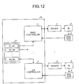
FIG. 12 is a block diagram illustrating a motor control device of the sixth embodiment. InFIG. 12 , the parts performing the same actions as in the first embodiment described above are denoted by the same symbols. As illustrated inFIG. 12 , the motor control device of the sixth embodiment includes a general controller 70 and a plurality of different models ofbrushless DC motors 3 that are driven to rotate by thedrivers 2 and for which rotation positions and/or the like are detected by thesensors 4. - The general controller 70 includes a plurality of
controllers 1 each of which is the same as the controller provided in any of the motor control devices of the above-described first to fifth embodiments. The general controller 70 has the same number ofcontrollers 1 as the number of thebrushless DC motors 3. The general controller 70 includes amemory 71. Thememory 71 stores, for eachbrushless motor 3, the coefficient A and the coefficient B of the G/F control unit 15 described above. The characters of "A1, B1" in thememory 71 inFIG. 12 represent the coefficient A and the coefficient B supplied to thefirst controller 1. Similarly, the characters of "An, Bn" in thememory 71 inFIG. 12 represent the coefficient A and the coefficient B supplied to the n-th controller 1. The "n" is a natural number. - That is, the
drivers 2, thebrushless DC motors 3, and thesensors 4 have different characteristics. Thus, thememory 71 stores therein the corresponding coefficient A and coefficient B for eachbrushless DC motor 3. Eachcontroller 1 performs rotation control of thebrushless DC motor 3 corresponding thereto, using a gain variable amount Gadj with an inclination corresponding to the coefficient A and the coefficient B for thecontroller 1. - In this manner, it is possible that the coefficient A and the coefficient B be optimized so as to cancel the rotation speed dependency of the mechanical time constant Tm and the electrical time constant Te of each
brushless DC motor 3 and be supplied to thecontroller 1. Therefore, even when thebrushless DC motors 3 different in characteristics (model) coexist, it is possible to perform optimal rotation control and obtain stable control performance. In addition, it is possible to obtain the same effects as in the embodiments described above. - The embodiment provides the effect that a rotation speed of the motor can be controlled stably and optimally.
- Although the invention has been described with respect to specific embodiments for a complete and clear disclosure, the appended claims are not to be thus limited but are to be construed as embodying all modifications and alternative constructions that may occur to one skilled in the art that fairly fall within the basic teaching herein set forth.
Claims (6)
- A motor control device (1) that controls a speed of a motor (3), the motor control device (1) comprising:a target speed generating unit (11) that generates a target speed;a speed detecting unit (14) that detects a current speed of the motor (3);a speed comparing unit (12) that compares the target speed (TgtSp) with the current speed to calculate a speed error;an error amplifying unit (13) that amplifies the speed error and outputs a control value; anda motor driving unit that drives the motor (3) in accordance with the control value, whereinthe error amplifying unit (13) has proportional integral characteristics by which the speed error is amplified with a proportional gain and integration is performed in a lower frequency range than an integral corner frequency, increases the proportional gain as the current speed is higher, and shifts the integral corner frequency to a lower frequency as the current speed is higher.
- The motor control device (1) according to claim 1, wherein the error amplifying unit (13) further has proportional differential characteristics by which differentiation is performed in a higher frequency range than a differential corner frequency, increases the proportional gain as the current speed is higher, and shifts the differential corner frequency to a higher frequency as the current speed is higher.
- The motor control device (1) according to claim 1 or 2, further comprising a gain variable unit (15) that linearly increases the proportional gain with a certain inclination in accordance with the current speed, with a value when the current speed is zero as a reference.
- The motor control device (1) according to claim 1 or 2, further comprising a gain variable unit (15) that linearly increases the proportional gain with a certain inclination in accordance with the current speed, with a value when the current speed is a certain value as a reference.
- The motor control device (1) according to claim 3 or 4, wherein the inclination is determined depending on a change rate of a mechanical time constant with respect to a rotation speed of the motor (3).
- A motor control device (70) comprising:the motor control device (1) according to any one of claims 3 to 5 for each of a plurality of motors (3), whereinthe gain variable unit (15) uses the inclination determined for each model of the motors (3).
Applications Claiming Priority (1)
| Application Number | Priority Date | Filing Date | Title |
|---|---|---|---|
| JP2013114496A JP6160258B2 (en) | 2013-05-30 | 2013-05-30 | Motor control device |
Publications (3)
| Publication Number | Publication Date |
|---|---|
| EP2808992A2 true EP2808992A2 (en) | 2014-12-03 |
| EP2808992A3 EP2808992A3 (en) | 2015-01-21 |
| EP2808992B1 EP2808992B1 (en) | 2018-10-10 |
Family
ID=50972446
Family Applications (1)
| Application Number | Title | Priority Date | Filing Date |
|---|---|---|---|
| EP14170490.8A Active EP2808992B1 (en) | 2013-05-30 | 2014-05-29 | Motor control device |
Country Status (3)
| Country | Link |
|---|---|
| US (1) | US9306483B2 (en) |
| EP (1) | EP2808992B1 (en) |
| JP (1) | JP6160258B2 (en) |
Cited By (1)
| Publication number | Priority date | Publication date | Assignee | Title |
|---|---|---|---|---|
| CN108964525A (en) * | 2017-05-18 | 2018-12-07 | 发那科株式会社 | Motor drive |
Families Citing this family (4)
| Publication number | Priority date | Publication date | Assignee | Title |
|---|---|---|---|---|
| JP6641794B2 (en) | 2015-08-28 | 2020-02-05 | 株式会社リコー | Motor drive device, motor control device, transport device, and motor drive method |
| JP2018004787A (en) * | 2016-06-29 | 2018-01-11 | 富士ゼロックス株式会社 | Image forming apparatus |
| CN112051725B (en) * | 2020-07-27 | 2024-04-02 | 河北汉光重工有限责任公司 | High-precision indirect transmission servo stable control method |
| CN119182316B (en) * | 2024-11-25 | 2025-02-11 | 西安庆安电气控制有限责任公司 | Control and regulation method for high-power direct-current motor |
Citations (1)
| Publication number | Priority date | Publication date | Assignee | Title |
|---|---|---|---|---|
| JP2009148082A (en) | 2007-12-14 | 2009-07-02 | Konica Minolta Business Technologies Inc | Image forming apparatus |
Family Cites Families (21)
| Publication number | Priority date | Publication date | Assignee | Title |
|---|---|---|---|---|
| JP2506914B2 (en) * | 1988-03-25 | 1996-06-12 | 松下電器産業株式会社 | Digital servo device |
| US4914361A (en) * | 1988-06-06 | 1990-04-03 | Hitachi, Ltd. | Method and apparatus for controlling the speed of moving body |
| JPH07118940B2 (en) * | 1988-06-06 | 1995-12-18 | 株式会社日立製作所 | Mobile speed control device |
| JP3231932B2 (en) * | 1994-01-10 | 2001-11-26 | 本田技研工業株式会社 | Electric power steering device |
| JP3252695B2 (en) * | 1996-03-01 | 2002-02-04 | 松下電器産業株式会社 | Motor control device |
| JP2000322105A (en) * | 1999-05-07 | 2000-11-24 | Toshiba Mach Co Ltd | Servo controller and method for stabilizing and adjusting servo controller |
| JP2002058278A (en) * | 2000-08-08 | 2002-02-22 | Canon Inc | Motor unit and image forming apparatus using the same |
| JP5111912B2 (en) * | 2006-05-10 | 2013-01-09 | 株式会社リコー | Motor drive device and image forming apparatus |
| JP2010141995A (en) | 2008-12-10 | 2010-06-24 | Canon Inc | Motor control apparatus and image forming apparatus |
| JP5317878B2 (en) | 2009-07-30 | 2013-10-16 | キヤノン株式会社 | Image forming apparatus |
| JP5392056B2 (en) | 2009-12-22 | 2014-01-22 | コニカミノルタ株式会社 | Image forming apparatus |
| JP5452405B2 (en) * | 2010-07-28 | 2014-03-26 | 株式会社日立ハイテクノロジーズ | Stage equipment |
| JP5618197B2 (en) | 2010-09-16 | 2014-11-05 | 株式会社リコー | Motor drive device |
| DE112011103674B9 (en) * | 2010-11-05 | 2016-11-17 | Mitsubishi Electric Corporation | Engine control unit |
| JP2012244856A (en) | 2011-05-23 | 2012-12-10 | Ricoh Co Ltd | Motor controller and image formation device |
| JP2012253542A (en) | 2011-06-02 | 2012-12-20 | Ricoh Co Ltd | Motor speed control device and image forming apparatus |
| US8928270B2 (en) | 2011-09-26 | 2015-01-06 | Ricoh Company, Ltd. | Electric motor system and motor control method |
| JP2013108971A (en) | 2011-10-25 | 2013-06-06 | Ricoh Co Ltd | Angle detector, motor drive device, and image forming apparatus |
| JP6014989B2 (en) | 2011-10-28 | 2016-10-26 | 株式会社リコー | Motor drive control apparatus and method |
| JP5919730B2 (en) | 2011-10-28 | 2016-05-18 | 株式会社リコー | Motor drive control apparatus and method |
| JP6064576B2 (en) | 2012-03-12 | 2017-01-25 | 株式会社リコー | Motor control device and motor control method |
-
2013
- 2013-05-30 JP JP2013114496A patent/JP6160258B2/en active Active
-
2014
- 2014-05-22 US US14/284,900 patent/US9306483B2/en active Active
- 2014-05-29 EP EP14170490.8A patent/EP2808992B1/en active Active
Patent Citations (1)
| Publication number | Priority date | Publication date | Assignee | Title |
|---|---|---|---|---|
| JP2009148082A (en) | 2007-12-14 | 2009-07-02 | Konica Minolta Business Technologies Inc | Image forming apparatus |
Cited By (1)
| Publication number | Priority date | Publication date | Assignee | Title |
|---|---|---|---|---|
| CN108964525A (en) * | 2017-05-18 | 2018-12-07 | 发那科株式会社 | Motor drive |
Also Published As
| Publication number | Publication date |
|---|---|
| JP2014236520A (en) | 2014-12-15 |
| JP6160258B2 (en) | 2017-07-12 |
| US9306483B2 (en) | 2016-04-05 |
| US20140354202A1 (en) | 2014-12-04 |
| EP2808992A3 (en) | 2015-01-21 |
| EP2808992B1 (en) | 2018-10-10 |
Similar Documents
| Publication | Publication Date | Title |
|---|---|---|
| EP2808992B1 (en) | Motor control device | |
| CN107921948B (en) | Electric Brake | |
| EP2644437A2 (en) | System and method for controlling a motor | |
| JP5917294B2 (en) | Motor drive circuit | |
| US11515822B2 (en) | Adaptive torque disturbance cancellation for electric motors | |
| JP5702126B2 (en) | Motor control circuit | |
| JP2014068522A (en) | Motor controlling device and motor controlling method | |
| US10992241B2 (en) | Control device of motor and storage medium | |
| CN101103517B (en) | Motor control device | |
| KR101994382B1 (en) | Motor control apparatus, image forming apparatus having the same and motor control method | |
| CN102859864B (en) | Method for controlling position and/or speed | |
| KR101954839B1 (en) | Driving device of seat for vehicle and control method thereof | |
| JP5845433B2 (en) | Motor drive device | |
| US7928674B2 (en) | Motor speed control systems | |
| US7026786B2 (en) | Reduced part count feedforward motor control | |
| CN112953345B (en) | Method, carrier and device for fast closed-loop control of average value of controlled variables | |
| US6815921B1 (en) | High performance motor control with feedforward bus supply voltage | |
| JPH07322664A (en) | Electric motor controller | |
| JP2019133537A (en) | Actuator controller and actuator control method | |
| KR20130000813A (en) | Electric power steering apparatus capable of adjusting offset | |
| JP2007020267A (en) | System identification device | |
| HK40072853A (en) | Method for online direct estimation and compensation of flux and torque errors in electric drives | |
| JP2009268218A (en) | Multi-shaft motor control system | |
| WO2025173425A1 (en) | Servo-amplifier adjustment method, program, and servo-amplifier adjustment device | |
| WO2015092463A1 (en) | Method for controlling an electric motor and sensor unit for implementing such a method |
Legal Events
| Date | Code | Title | Description |
|---|---|---|---|
| PUAI | Public reference made under article 153(3) epc to a published international application that has entered the european phase |
Free format text: ORIGINAL CODE: 0009012 |
|
| 17P | Request for examination filed |
Effective date: 20140529 |
|
| AK | Designated contracting states |
Kind code of ref document: A2 Designated state(s): AL AT BE BG CH CY CZ DE DK EE ES FI FR GB GR HR HU IE IS IT LI LT LU LV MC MK MT NL NO PL PT RO RS SE SI SK SM TR |
|
| AX | Request for extension of the european patent |
Extension state: BA ME |
|
| PUAL | Search report despatched |
Free format text: ORIGINAL CODE: 0009013 |
|
| AK | Designated contracting states |
Kind code of ref document: A3 Designated state(s): AL AT BE BG CH CY CZ DE DK EE ES FI FR GB GR HR HU IE IS IT LI LT LU LV MC MK MT NL NO PL PT RO RS SE SI SK SM TR |
|
| AX | Request for extension of the european patent |
Extension state: BA ME |
|
| RIC1 | Information provided on ipc code assigned before grant |
Ipc: H02P 23/00 20060101ALI20141212BHEP Ipc: G03G 15/00 20060101ALI20141212BHEP Ipc: H02M 7/49 20070101AFI20141212BHEP |
|
| RIC1 | Information provided on ipc code assigned before grant |
Ipc: H02M 7/49 20070101AFI20180412BHEP Ipc: G03G 15/00 20060101ALI20180412BHEP Ipc: H02P 23/00 20060101ALI20180412BHEP |
|
| GRAP | Despatch of communication of intention to grant a patent |
Free format text: ORIGINAL CODE: EPIDOSNIGR1 |
|
| STAA | Information on the status of an ep patent application or granted ep patent |
Free format text: STATUS: GRANT OF PATENT IS INTENDED |
|
| INTG | Intention to grant announced |
Effective date: 20180522 |
|
| GRAS | Grant fee paid |
Free format text: ORIGINAL CODE: EPIDOSNIGR3 |
|
| GRAA | (expected) grant |
Free format text: ORIGINAL CODE: 0009210 |
|
| STAA | Information on the status of an ep patent application or granted ep patent |
Free format text: STATUS: THE PATENT HAS BEEN GRANTED |
|
| AK | Designated contracting states |
Kind code of ref document: B1 Designated state(s): AL AT BE BG CH CY CZ DE DK EE ES FI FR GB GR HR HU IE IS IT LI LT LU LV MC MK MT NL NO PL PT RO RS SE SI SK SM TR |
|
| REG | Reference to a national code |
Ref country code: GB Ref legal event code: FG4D |
|
| REG | Reference to a national code |
Ref country code: CH Ref legal event code: EP Ref country code: AT Ref legal event code: REF Ref document number: 1052414 Country of ref document: AT Kind code of ref document: T Effective date: 20181015 |
|
| REG | Reference to a national code |
Ref country code: IE Ref legal event code: FG4D |
|
| REG | Reference to a national code |
Ref country code: DE Ref legal event code: R096 Ref document number: 602014033667 Country of ref document: DE |
|
| REG | Reference to a national code |
Ref country code: NL Ref legal event code: MP Effective date: 20181010 |
|
| REG | Reference to a national code |
Ref country code: LT Ref legal event code: MG4D |
|
| REG | Reference to a national code |
Ref country code: AT Ref legal event code: MK05 Ref document number: 1052414 Country of ref document: AT Kind code of ref document: T Effective date: 20181010 |
|
| PG25 | Lapsed in a contracting state [announced via postgrant information from national office to epo] |
Ref country code: NL Free format text: LAPSE BECAUSE OF FAILURE TO SUBMIT A TRANSLATION OF THE DESCRIPTION OR TO PAY THE FEE WITHIN THE PRESCRIBED TIME-LIMIT Effective date: 20181010 |
|
| PG25 | Lapsed in a contracting state [announced via postgrant information from national office to epo] |
Ref country code: HR Free format text: LAPSE BECAUSE OF FAILURE TO SUBMIT A TRANSLATION OF THE DESCRIPTION OR TO PAY THE FEE WITHIN THE PRESCRIBED TIME-LIMIT Effective date: 20181010 Ref country code: PL Free format text: LAPSE BECAUSE OF FAILURE TO SUBMIT A TRANSLATION OF THE DESCRIPTION OR TO PAY THE FEE WITHIN THE PRESCRIBED TIME-LIMIT Effective date: 20181010 Ref country code: BG Free format text: LAPSE BECAUSE OF FAILURE TO SUBMIT A TRANSLATION OF THE DESCRIPTION OR TO PAY THE FEE WITHIN THE PRESCRIBED TIME-LIMIT Effective date: 20190110 Ref country code: LT Free format text: LAPSE BECAUSE OF FAILURE TO SUBMIT A TRANSLATION OF THE DESCRIPTION OR TO PAY THE FEE WITHIN THE PRESCRIBED TIME-LIMIT Effective date: 20181010 Ref country code: ES Free format text: LAPSE BECAUSE OF FAILURE TO SUBMIT A TRANSLATION OF THE DESCRIPTION OR TO PAY THE FEE WITHIN THE PRESCRIBED TIME-LIMIT Effective date: 20181010 Ref country code: IS Free format text: LAPSE BECAUSE OF FAILURE TO SUBMIT A TRANSLATION OF THE DESCRIPTION OR TO PAY THE FEE WITHIN THE PRESCRIBED TIME-LIMIT Effective date: 20190210 Ref country code: AT Free format text: LAPSE BECAUSE OF FAILURE TO SUBMIT A TRANSLATION OF THE DESCRIPTION OR TO PAY THE FEE WITHIN THE PRESCRIBED TIME-LIMIT Effective date: 20181010 Ref country code: NO Free format text: LAPSE BECAUSE OF FAILURE TO SUBMIT A TRANSLATION OF THE DESCRIPTION OR TO PAY THE FEE WITHIN THE PRESCRIBED TIME-LIMIT Effective date: 20190110 Ref country code: FI Free format text: LAPSE BECAUSE OF FAILURE TO SUBMIT A TRANSLATION OF THE DESCRIPTION OR TO PAY THE FEE WITHIN THE PRESCRIBED TIME-LIMIT Effective date: 20181010 Ref country code: LV Free format text: LAPSE BECAUSE OF FAILURE TO SUBMIT A TRANSLATION OF THE DESCRIPTION OR TO PAY THE FEE WITHIN THE PRESCRIBED TIME-LIMIT Effective date: 20181010 |
|
| PG25 | Lapsed in a contracting state [announced via postgrant information from national office to epo] |
Ref country code: SE Free format text: LAPSE BECAUSE OF FAILURE TO SUBMIT A TRANSLATION OF THE DESCRIPTION OR TO PAY THE FEE WITHIN THE PRESCRIBED TIME-LIMIT Effective date: 20181010 Ref country code: AL Free format text: LAPSE BECAUSE OF FAILURE TO SUBMIT A TRANSLATION OF THE DESCRIPTION OR TO PAY THE FEE WITHIN THE PRESCRIBED TIME-LIMIT Effective date: 20181010 Ref country code: RS Free format text: LAPSE BECAUSE OF FAILURE TO SUBMIT A TRANSLATION OF THE DESCRIPTION OR TO PAY THE FEE WITHIN THE PRESCRIBED TIME-LIMIT Effective date: 20181010 Ref country code: PT Free format text: LAPSE BECAUSE OF FAILURE TO SUBMIT A TRANSLATION OF THE DESCRIPTION OR TO PAY THE FEE WITHIN THE PRESCRIBED TIME-LIMIT Effective date: 20190210 Ref country code: GR Free format text: LAPSE BECAUSE OF FAILURE TO SUBMIT A TRANSLATION OF THE DESCRIPTION OR TO PAY THE FEE WITHIN THE PRESCRIBED TIME-LIMIT Effective date: 20190111 |
|
| REG | Reference to a national code |
Ref country code: DE Ref legal event code: R097 Ref document number: 602014033667 Country of ref document: DE |
|
| PG25 | Lapsed in a contracting state [announced via postgrant information from national office to epo] |
Ref country code: DK Free format text: LAPSE BECAUSE OF FAILURE TO SUBMIT A TRANSLATION OF THE DESCRIPTION OR TO PAY THE FEE WITHIN THE PRESCRIBED TIME-LIMIT Effective date: 20181010 Ref country code: CZ Free format text: LAPSE BECAUSE OF FAILURE TO SUBMIT A TRANSLATION OF THE DESCRIPTION OR TO PAY THE FEE WITHIN THE PRESCRIBED TIME-LIMIT Effective date: 20181010 Ref country code: IT Free format text: LAPSE BECAUSE OF FAILURE TO SUBMIT A TRANSLATION OF THE DESCRIPTION OR TO PAY THE FEE WITHIN THE PRESCRIBED TIME-LIMIT Effective date: 20181010 |
|
| PLBE | No opposition filed within time limit |
Free format text: ORIGINAL CODE: 0009261 |
|
| STAA | Information on the status of an ep patent application or granted ep patent |
Free format text: STATUS: NO OPPOSITION FILED WITHIN TIME LIMIT |
|
| PG25 | Lapsed in a contracting state [announced via postgrant information from national office to epo] |
Ref country code: RO Free format text: LAPSE BECAUSE OF FAILURE TO SUBMIT A TRANSLATION OF THE DESCRIPTION OR TO PAY THE FEE WITHIN THE PRESCRIBED TIME-LIMIT Effective date: 20181010 Ref country code: SM Free format text: LAPSE BECAUSE OF FAILURE TO SUBMIT A TRANSLATION OF THE DESCRIPTION OR TO PAY THE FEE WITHIN THE PRESCRIBED TIME-LIMIT Effective date: 20181010 Ref country code: EE Free format text: LAPSE BECAUSE OF FAILURE TO SUBMIT A TRANSLATION OF THE DESCRIPTION OR TO PAY THE FEE WITHIN THE PRESCRIBED TIME-LIMIT Effective date: 20181010 Ref country code: SK Free format text: LAPSE BECAUSE OF FAILURE TO SUBMIT A TRANSLATION OF THE DESCRIPTION OR TO PAY THE FEE WITHIN THE PRESCRIBED TIME-LIMIT Effective date: 20181010 |
|
| 26N | No opposition filed |
Effective date: 20190711 |
|
| PG25 | Lapsed in a contracting state [announced via postgrant information from national office to epo] |
Ref country code: SI Free format text: LAPSE BECAUSE OF FAILURE TO SUBMIT A TRANSLATION OF THE DESCRIPTION OR TO PAY THE FEE WITHIN THE PRESCRIBED TIME-LIMIT Effective date: 20181010 |
|
| REG | Reference to a national code |
Ref country code: CH Ref legal event code: PL |
|
| PG25 | Lapsed in a contracting state [announced via postgrant information from national office to epo] |
Ref country code: MC Free format text: LAPSE BECAUSE OF FAILURE TO SUBMIT A TRANSLATION OF THE DESCRIPTION OR TO PAY THE FEE WITHIN THE PRESCRIBED TIME-LIMIT Effective date: 20181010 Ref country code: CH Free format text: LAPSE BECAUSE OF NON-PAYMENT OF DUE FEES Effective date: 20190531 Ref country code: LI Free format text: LAPSE BECAUSE OF NON-PAYMENT OF DUE FEES Effective date: 20190531 |
|
| REG | Reference to a national code |
Ref country code: BE Ref legal event code: MM Effective date: 20190531 |
|
| PG25 | Lapsed in a contracting state [announced via postgrant information from national office to epo] |
Ref country code: LU Free format text: LAPSE BECAUSE OF NON-PAYMENT OF DUE FEES Effective date: 20190529 |
|
| PG25 | Lapsed in a contracting state [announced via postgrant information from national office to epo] |
Ref country code: TR Free format text: LAPSE BECAUSE OF FAILURE TO SUBMIT A TRANSLATION OF THE DESCRIPTION OR TO PAY THE FEE WITHIN THE PRESCRIBED TIME-LIMIT Effective date: 20181010 |
|
| PG25 | Lapsed in a contracting state [announced via postgrant information from national office to epo] |
Ref country code: IE Free format text: LAPSE BECAUSE OF NON-PAYMENT OF DUE FEES Effective date: 20190529 |
|
| PG25 | Lapsed in a contracting state [announced via postgrant information from national office to epo] |
Ref country code: BE Free format text: LAPSE BECAUSE OF NON-PAYMENT OF DUE FEES Effective date: 20190531 |
|
| PG25 | Lapsed in a contracting state [announced via postgrant information from national office to epo] |
Ref country code: CY Free format text: LAPSE BECAUSE OF FAILURE TO SUBMIT A TRANSLATION OF THE DESCRIPTION OR TO PAY THE FEE WITHIN THE PRESCRIBED TIME-LIMIT Effective date: 20181010 |
|
| PG25 | Lapsed in a contracting state [announced via postgrant information from national office to epo] |
Ref country code: MT Free format text: LAPSE BECAUSE OF FAILURE TO SUBMIT A TRANSLATION OF THE DESCRIPTION OR TO PAY THE FEE WITHIN THE PRESCRIBED TIME-LIMIT Effective date: 20181010 Ref country code: HU Free format text: LAPSE BECAUSE OF FAILURE TO SUBMIT A TRANSLATION OF THE DESCRIPTION OR TO PAY THE FEE WITHIN THE PRESCRIBED TIME-LIMIT; INVALID AB INITIO Effective date: 20140529 |
|
| PG25 | Lapsed in a contracting state [announced via postgrant information from national office to epo] |
Ref country code: MK Free format text: LAPSE BECAUSE OF FAILURE TO SUBMIT A TRANSLATION OF THE DESCRIPTION OR TO PAY THE FEE WITHIN THE PRESCRIBED TIME-LIMIT Effective date: 20181010 |
|
| P01 | Opt-out of the competence of the unified patent court (upc) registered |
Effective date: 20230522 |
|
| PGFP | Annual fee paid to national office [announced via postgrant information from national office to epo] |
Ref country code: DE Payment date: 20250521 Year of fee payment: 12 |
|
| PGFP | Annual fee paid to national office [announced via postgrant information from national office to epo] |
Ref country code: GB Payment date: 20250521 Year of fee payment: 12 |
|
| PGFP | Annual fee paid to national office [announced via postgrant information from national office to epo] |
Ref country code: FR Payment date: 20250528 Year of fee payment: 12 |