EP2644437A2 - System and method for controlling a motor - Google Patents
System and method for controlling a motor Download PDFInfo
- Publication number
- EP2644437A2 EP2644437A2 EP13160793.9A EP13160793A EP2644437A2 EP 2644437 A2 EP2644437 A2 EP 2644437A2 EP 13160793 A EP13160793 A EP 13160793A EP 2644437 A2 EP2644437 A2 EP 2644437A2
- Authority
- EP
- European Patent Office
- Prior art keywords
- torque
- assist motor
- motor
- electrical current
- gain
- Prior art date
- Legal status (The legal status is an assumption and is not a legal conclusion. Google has not performed a legal analysis and makes no representation as to the accuracy of the status listed.)
- Withdrawn
Links
Images


Classifications
-
- B—PERFORMING OPERATIONS; TRANSPORTING
- B62—LAND VEHICLES FOR TRAVELLING OTHERWISE THAN ON RAILS
- B62D—MOTOR VEHICLES; TRAILERS
- B62D5/00—Power-assisted or power-driven steering
- B62D5/04—Power-assisted or power-driven steering electrical, e.g. using an electric servo-motor connected to, or forming part of, the steering gear
- B62D5/0457—Power-assisted or power-driven steering electrical, e.g. using an electric servo-motor connected to, or forming part of, the steering gear characterised by control features of the drive means as such
- B62D5/046—Controlling the motor
-
- B—PERFORMING OPERATIONS; TRANSPORTING
- B60—VEHICLES IN GENERAL
- B60L—PROPULSION OF ELECTRICALLY-PROPELLED VEHICLES; SUPPLYING ELECTRIC POWER FOR AUXILIARY EQUIPMENT OF ELECTRICALLY-PROPELLED VEHICLES; ELECTRODYNAMIC BRAKE SYSTEMS FOR VEHICLES IN GENERAL; MAGNETIC SUSPENSION OR LEVITATION FOR VEHICLES; MONITORING OPERATING VARIABLES OF ELECTRICALLY-PROPELLED VEHICLES; ELECTRIC SAFETY DEVICES FOR ELECTRICALLY-PROPELLED VEHICLES
- B60L15/00—Methods, circuits, or devices for controlling the traction-motor speed of electrically-propelled vehicles
- B60L15/02—Methods, circuits, or devices for controlling the traction-motor speed of electrically-propelled vehicles characterised by the form of the current used in the control circuit
- B60L15/025—Methods, circuits, or devices for controlling the traction-motor speed of electrically-propelled vehicles characterised by the form of the current used in the control circuit using field orientation; Vector control; Direct Torque Control [DTC]
-
- H—ELECTRICITY
- H02—GENERATION; CONVERSION OR DISTRIBUTION OF ELECTRIC POWER
- H02P—CONTROL OR REGULATION OF ELECTRIC MOTORS, ELECTRIC GENERATORS OR DYNAMO-ELECTRIC CONVERTERS; CONTROLLING TRANSFORMERS, REACTORS OR CHOKE COILS
- H02P6/00—Arrangements for controlling synchronous motors or other dynamo-electric motors using electronic commutation dependent on the rotor position; Electronic commutators therefor
- H02P6/08—Arrangements for controlling the speed or torque of a single motor
-
- H—ELECTRICITY
- H02—GENERATION; CONVERSION OR DISTRIBUTION OF ELECTRIC POWER
- H02P—CONTROL OR REGULATION OF ELECTRIC MOTORS, ELECTRIC GENERATORS OR DYNAMO-ELECTRIC CONVERTERS; CONTROLLING TRANSFORMERS, REACTORS OR CHOKE COILS
- H02P6/00—Arrangements for controlling synchronous motors or other dynamo-electric motors using electronic commutation dependent on the rotor position; Electronic commutators therefor
- H02P6/14—Electronic commutators
- H02P6/16—Circuit arrangements for detecting position
- H02P6/17—Circuit arrangements for detecting position and for generating speed information
-
- Y—GENERAL TAGGING OF NEW TECHNOLOGICAL DEVELOPMENTS; GENERAL TAGGING OF CROSS-SECTIONAL TECHNOLOGIES SPANNING OVER SEVERAL SECTIONS OF THE IPC; TECHNICAL SUBJECTS COVERED BY FORMER USPC CROSS-REFERENCE ART COLLECTIONS [XRACs] AND DIGESTS
- Y02—TECHNOLOGIES OR APPLICATIONS FOR MITIGATION OR ADAPTATION AGAINST CLIMATE CHANGE
- Y02T—CLIMATE CHANGE MITIGATION TECHNOLOGIES RELATED TO TRANSPORTATION
- Y02T10/00—Road transport of goods or passengers
- Y02T10/60—Other road transportation technologies with climate change mitigation effect
- Y02T10/64—Electric machine technologies in electromobility
-
- Y—GENERAL TAGGING OF NEW TECHNOLOGICAL DEVELOPMENTS; GENERAL TAGGING OF CROSS-SECTIONAL TECHNOLOGIES SPANNING OVER SEVERAL SECTIONS OF THE IPC; TECHNICAL SUBJECTS COVERED BY FORMER USPC CROSS-REFERENCE ART COLLECTIONS [XRACs] AND DIGESTS
- Y02—TECHNOLOGIES OR APPLICATIONS FOR MITIGATION OR ADAPTATION AGAINST CLIMATE CHANGE
- Y02T—CLIMATE CHANGE MITIGATION TECHNOLOGIES RELATED TO TRANSPORTATION
- Y02T10/00—Road transport of goods or passengers
- Y02T10/60—Other road transportation technologies with climate change mitigation effect
- Y02T10/72—Electric energy management in electromobility
Definitions
- the subject invention relates to systems and methods for controlling a motor and, more particularly, to systems and methods for controlling operation of a torque-assist motor of an electrical power-assist system of a motor vehicle.
- either or both of the proportional gain and the integral gain can be adjusted to achieve increased frequency response, and thus greater bandwidth.
- a feedback controller such as a PI controller
- increases in gain often entail the negative consequence of amplifying noise that is inherent in the feedback signal (e.g., the current signal).
- the amplification of noise associated with the current that drives the assist motor can produce vibrations in the vehicle steering handwheel, which vibrations may be particularly noticeable when the vehicle is stationary or moving at a relatively low speed such that an operator might expect to experience little to no handwheel vibration.
- a system for controlling operation of a torque-assist motor of an electrical power-assist system of a motor vehicle comprises a motor speed calculation module, a gain calculation module, an error calculation module, a controller module, and an inverter.
- a motor position sensor is configured and arranged for determining a rotational position of the torque-assist motor, and a current sensor configured to detect an electrical current applied to the torque-assist motor.
- the motor speed calculation module is configured to produce a motor speed signal that is indicative of a rotational speed of the torque-assist motor and that is based on a change in the rotational position of the torque-assist motor over a period of time.
- the gain calculation module is configured to produce one or more gain factors based on the rotational speed of the torque-assist motor.
- the error calculation module is configured to calculate a current error based on a commanded electrical current and the electrical current applied to the torque-assist motor, and the controller module is configured to calculate a quadrature axis voltage based on the current error and the one or more gain factors.
- the inverter is driven by a direct voltage signal that is phased with the rotational position of the torque-assist motor, and is configured to produce the electrical current applied to the torque-assist motor. A characteristic of the electrical current applied to the torque-assist motor is affected by the quadrature axis voltage.
- a method for controlling operation of a torque-assist motor of an electrical power-assist system of a motor vehicle comprises determining a rotational position of the torque-assist motor and producing a motor speed signal that is indicative of a rotational speed of the torque-assist motor and that is based on a change in the rotational position of the torque-assist motor over a period of time.
- One or more gain factors are produced based on the rotational speed of the torque-assist motor.
- An electrical current applied to the torque-assist motor is detected, and a current error is calculated based on a commanded electrical current and the electrical current applied to the torque-assist motor.
- a quadrature axis voltage is calculated based on the current error and the one or more gain factors.
- An inverter is driven with a direct voltage signal that is phased with the rotational position of the torque-assist motor so as to produce the electrical current applied to the torque-assist motor.
- the electrical current exhibits a characteristic that is affected by the quadrature axis voltage.
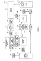
- FIG. 1 is a functional block diagram of an exemplary system for controlling operation of a torque-assist motor of an electrical power-assist system of a motor vehicle;
- FIG. 2 is a chart showing an exemplary relationship between an integral gain factor and motor speed
- FIG. 3 is a chart showing an exemplary relationship between a proportional gain factor and motor speed
- FIG. 4 illustrates a method for controlling operation of a torque-assist motor of an electrical power-assist system of a motor vehicle.
- module refers to an Application Specific Integrated Circuit (ASIC), an electronic circuit, a processor (shared, dedicated, or group) and memory that execute one or more software or firmware programs, a combinational logic circuit, and/or other suitable components that provide the described functionality.
- ASIC Application Specific Integrated Circuit
- processor shared, dedicated, or group
- memory that execute one or more software or firmware programs, a combinational logic circuit, and/or other suitable components that provide the described functionality.
- FIG. 1 shows an exemplary embodiment of a feedback control system 100 that is configured for controlling the operation of a torque-assist motor 102.
- torque assist motor 102 is a permanent-magnet, alternating-current motor configured and arranged so as to provide torque assistance to the steering system (not shown) of a motor vehicle (not shown).
- a motor position sensor 104 is positioned and configured so as to periodically or continuously detect a rotational (i.e., angular) position 106 of the output shaft 108 driven by torque-assist motor 102 and to communicate such detected positions (i.e., information indicative of such detected positions) 106 to a motor speed calculation module 112. Based on the variations in the detected positions 106 of the output shaft 108 over time, the motor speed calculation module 112 produces motor speed signals 114, which are periodically or continuously communicated to a gain calculation module 116.
- the gain calculation module 116 is configured to produce integral gain factors 118 based on the motor speed signals 114 and a pre-established relationship 120 between the integral gain factors 118 and the motor speed signals 114.
- the gain calculation module 116 is also configured to produce proportional gain factors 122 based on the motor speed signals 114 and a pre-established relationship 124 between the proportional gain factors 122 and the motor speed signals 114.
- a pre-established relationship 120 between the integral gain factors 118 and the motor speed signals 114 is used by the gain calculation module 116 to produce the integral gain factors 118 based on the motor speed signals 114.
- a pre-established relationship 124 between the proportional gain factors 122 and the motor speed signals 114 is used by the gain calculation module 116 to produce the proportional gain factors 122 based on the motor speed signals 114.
- the relationships 120 and 124 are pre-established based on empirical data and are configured so as to provide acceptably responsive and stable control over the operation of the torque-assist motor 102 while preventing unnecessary amplification of noise that may be inherent in signals used by feedback control system 100.
- a current sensor 126 is positioned and configured so as to periodically or continuously detect an instantaneous, alternating electrical current 128 that is applied to (i.e., drawn by) the torque-assist motor 102.
- the current sensor 126 is also configured to communicate such detected electrical current 128, or information indicative of such detected electrical current, to an error calculation module 130.
- Error calculation module 130 also receives information that is indicative of a commanded electrical current 132 and calculates a current error 134 that is based on a difference between, or a ratio of, the commanded electrical current 132, which is based on a torque applied by the vehicle operator to the vehicle handwheel, and the electrical current 128 that is actually applied to (i.e., drawn by) the torque-assist motor 102.
- Error calculation module 130 communicates the current error 134 to a controller module 136, which receives the current error 134 from the error calculation module 130 and also receives the integral gain factors 118 and the proportional gain factors 122 from the gain calculation module 116.
- the controller module 136 calculates a quadrature axis voltage 138 based on the current error 134, the integral gain factors 118, and the proportional gain factors 122.
- the quadrature axis voltage 138 is based on a sum of two terms, wherein the first term represents a product of the integral gain factors 118 and an integrated (i.e., accumulated) amount of current error 134 over a representative time period, and wherein the second term represents a product of the proportional gain factor 122 and the instantaneous amount of current error 134.
- the controller module 136 provides the quadrature axis voltage 138 to an inverter (i.e., a switching bridge) 140, which is driven by a direct voltage signal 142 phased with the rotational (i.e., angular) position 106 of the output shaft 108, as sensed by the motor position sensor 104. Being dependent upon the current error 134 and the proportional gain factor 122 and the integral gain factor 118, the quadrature axis voltage 138 is effective to impact the magnitude (i.e. amplitude) of the alternating current 128 that is produced by the inverter 140 and used to drive the torque-assist motor 102.
- an inverter i.e., a switching bridge
- gain calculation module 116 dynamically adjusts the integral gain factors 118 and the proportional gain factors 122 according to the motor speed signals 114, which are indicative of the rotational speed of the torque assist motor 102, and thus the extent of torque assistance being applied to the vehicle handwheel, the gain can be affected via the pre-established relationships 120 and 124 so as to provide relatively greater levels of gain, and thus greater frequency response, at higher torque assist motor speeds while reducing the gain levels at relatively lower at lower speeds.
- relatively low gains applied at low motor speeds tend to mitigate the impact of any noise that is present in the current feedback signal at those lower motor speeds, such as where unnecessary amplification of such noise could otherwise cause perceptible vibration in the vehicle handwheel.
- increased gains may be implemented at greater torque-assist motor speeds so as to provide increased frequency response (i.e., higher bandwidth).
- FIG. 4 shows an exemplary method 400 for controlling the operation of a torque-assist motor that is configured and arranged for providing torque assistance to a steering wheel of a motor vehicle.
- a rotational (i.e., angular) position of the output shaft of the torque-assist motor is periodically or continuously detected (step 402) and communicated (step 404) so as to facilitate calculation (step 406) of the motor speed.
- Signals indicating the calculated motor speed are provided (step 408) so as to facilitate calculation of both integral gain factors and proportional gain factors that are responsive to changes in motor speed (step 410).
- the calculations of both integral gain factors and proportional gain factors (step 410) may be based on pre-established relationships between the integral and proportional gain factors and the motor velocities. In an exemplary embodiment, these pre-established relationships are configured so as to provide acceptably responsive and stable control over the operation of the torque-assist motor while preventing unnecessary amplification of noise that may be inherent in signals used by feedback control system.
- the instantaneous, alternating electrical current that is actually applied to (i.e., drawn by) the torque-assist motor is periodically or continuously sensed (step 412) so as to facilitate providing (step 414) the detected electrical current, or information indicative of the detected electrical current, to enable calculation (step 416) of an error value that is based on a difference between the detected electrical current and a commanded electrical current (which is itself based on a torque applied to the vehicle handwheel by an operator of the vehicle).
- the error term is provided (step 418) so as to facilitate calculation (step 420) of a quadrature axis voltage based on the instantaneous error value, and accumulated error value, as well as both the integral gain factor and the proportional gain factor corresponding to the instantaneous speed of the torque-assist motor.
- the quadrature axis voltage is calculated (step 420) based on a sum of two terms, wherein the first term represents a product of the integral gain factors and an integrated (i.e., accumulated) amount of current error over a representative time period, and wherein the second term represents a product of the proportional gain factor and the instantaneous amount of current error.
- the quadrature axis voltage is provided (step 422) so as to affect an alternating current produced from a direct voltage signal that is phased with the rotational (i.e., angular) position of the output shaft of the torque-assist motor. Being dependent upon the current error and the proportional gain factor and the integral gain factor, the quadrature axis voltage is effective to impact the magnitude (i.e. amplitude) of the alternating current, which drives the torque-assist motor.
- the gain can be affected via the pre-established relationships so as to provide relatively greater levels of gain, and thus greater frequency response, at higher torque assist motor speeds while reducing the gain levels at relatively lower at lower speeds.
- relatively low gains applied at low motor speeds tend to mitigate the impact of any noise that is present in the current feedback signal at those lower motor speeds, such as where unnecessary amplification of such noise could otherwise cause perceptible vibration in the vehicle handwheel.
- increased gains may be implemented at greater torque-assist motor speeds so as to provide increased frequency response (i.e., higher bandwidth).
Abstract
Description
- The subject invention relates to systems and methods for controlling a motor and, more particularly, to systems and methods for controlling operation of a torque-assist motor of an electrical power-assist system of a motor vehicle.
- In a permanent magnet machine, in which current is controlled using a feedback controller, such as a PI controller, either or both of the proportional gain and the integral gain can be adjusted to achieve increased frequency response, and thus greater bandwidth. Unfortunately, however, increases in gain often entail the negative consequence of amplifying noise that is inherent in the feedback signal (e.g., the current signal). In a vehicle steering system with electric power assist, the amplification of noise associated with the current that drives the assist motor can produce vibrations in the vehicle steering handwheel, which vibrations may be particularly noticeable when the vehicle is stationary or moving at a relatively low speed such that an operator might expect to experience little to no handwheel vibration.
- Accordingly, it is desirable to have an improved system and method for controlling electric power assist of vehicle steering systems wherein current gain may be adjusted so as to achieve increased frequency response (i.e., bandwidth) while also providing for attenuation of handwheel vibration at relatively low speeds.
- In one exemplary embodiment of the invention, a system for controlling operation of a torque-assist motor of an electrical power-assist system of a motor vehicle comprises a motor speed calculation module, a gain calculation module, an error calculation module, a controller module, and an inverter. A motor position sensor is configured and arranged for determining a rotational position of the torque-assist motor, and a current sensor configured to detect an electrical current applied to the torque-assist motor. The motor speed calculation module is configured to produce a motor speed signal that is indicative of a rotational speed of the torque-assist motor and that is based on a change in the rotational position of the torque-assist motor over a period of time. The gain calculation module is configured to produce one or more gain factors based on the rotational speed of the torque-assist motor. The error calculation module is configured to calculate a current error based on a commanded electrical current and the electrical current applied to the torque-assist motor, and the controller module is configured to calculate a quadrature axis voltage based on the current error and the one or more gain factors. The inverter is driven by a direct voltage signal that is phased with the rotational position of the torque-assist motor, and is configured to produce the electrical current applied to the torque-assist motor. A characteristic of the electrical current applied to the torque-assist motor is affected by the quadrature axis voltage.
- In another exemplary embodiment of the invention, a method for controlling operation of a torque-assist motor of an electrical power-assist system of a motor vehicle comprises determining a rotational position of the torque-assist motor and producing a motor speed signal that is indicative of a rotational speed of the torque-assist motor and that is based on a change in the rotational position of the torque-assist motor over a period of time. One or more gain factors are produced based on the rotational speed of the torque-assist motor. An electrical current applied to the torque-assist motor is detected, and a current error is calculated based on a commanded electrical current and the electrical current applied to the torque-assist motor. A quadrature axis voltage is calculated based on the current error and the one or more gain factors. An inverter is driven with a direct voltage signal that is phased with the rotational position of the torque-assist motor so as to produce the electrical current applied to the torque-assist motor. The electrical current exhibits a characteristic that is affected by the quadrature axis voltage.
- The above features and advantages and other features and advantages of the invention are readily apparent from the following detailed description of the invention when taken in connection with the accompanying drawings.
- The subject matter which is regarded as the invention is particularly pointed out and distinctly claimed in the claims at the conclusion of the specification. The foregoing and advantages and details appear, by way of example only, in the following detailed description of embodiments taken in conjunction with the accompanying drawings in which:
-
FIG. 1 is a functional block diagram of an exemplary system for controlling operation of a torque-assist motor of an electrical power-assist system of a motor vehicle; -
FIG. 2 is a chart showing an exemplary relationship between an integral gain factor and motor speed; -
FIG. 3 is a chart showing an exemplary relationship between a proportional gain factor and motor speed; and -
FIG. 4 illustrates a method for controlling operation of a torque-assist motor of an electrical power-assist system of a motor vehicle. - The following description is merely exemplary in nature and is in no way intended to limit the disclosure, its application, or uses. For purposes of clarity, the same reference numbers will be used in the drawings to identify similar elements. As used herein, the phrase at least one of A, B, and C should be construed to mean a logical (A or B or C), using a non-exclusive logical or. It should be understood that steps within a method may be executed in different order without altering the principles of the present disclosure.
- As used herein, the term "module" refers to an Application Specific Integrated Circuit (ASIC), an electronic circuit, a processor (shared, dedicated, or group) and memory that execute one or more software or firmware programs, a combinational logic circuit, and/or other suitable components that provide the described functionality.
- Referring now to the Figures, in which the invention will be described with reference to specific embodiments, without limiting same,
FIG. 1 shows an exemplary embodiment of afeedback control system 100 that is configured for controlling the operation of a torque-assist motor 102. In the illustrated embodiment,torque assist motor 102 is a permanent-magnet, alternating-current motor configured and arranged so as to provide torque assistance to the steering system (not shown) of a motor vehicle (not shown). To facilitate effective control over the operation of torque-assist motor 102, amotor position sensor 104 is positioned and configured so as to periodically or continuously detect a rotational (i.e., angular)position 106 of theoutput shaft 108 driven by torque-assist motor 102 and to communicate such detected positions (i.e., information indicative of such detected positions) 106 to a motorspeed calculation module 112. Based on the variations in the detectedpositions 106 of theoutput shaft 108 over time, the motorspeed calculation module 112 producesmotor speed signals 114, which are periodically or continuously communicated to again calculation module 116. - The
gain calculation module 116 is configured to produceintegral gain factors 118 based on themotor speed signals 114 and a pre-establishedrelationship 120 between theintegral gain factors 118 and themotor speed signals 114. Thegain calculation module 116 is also configured to produceproportional gain factors 122 based on themotor speed signals 114 and a pre-establishedrelationship 124 between theproportional gain factors 122 and themotor speed signals 114. In an exemplary embodiment, apre-established relationship 120 between theintegral gain factors 118 and themotor speed signals 114, such theexemplary relationship 120 shown onFIG. 2 , is used by thegain calculation module 116 to produce theintegral gain factors 118 based on themotor speed signals 114. - Similarly, a pre-established
relationship 124 between theproportional gain factors 122 and themotor speed signals 114, such theexemplary relationship 124 shown onFIG. 3 , is used by thegain calculation module 116 to produce theproportional gain factors 122 based on themotor speed signals 114. In an exemplary embodiment, therelationships assist motor 102 while preventing unnecessary amplification of noise that may be inherent in signals used byfeedback control system 100. - In an exemplary embodiment, a
current sensor 126 is positioned and configured so as to periodically or continuously detect an instantaneous, alternatingelectrical current 128 that is applied to (i.e., drawn by) the torque-assist motor 102. Thecurrent sensor 126 is also configured to communicate such detectedelectrical current 128, or information indicative of such detected electrical current, to anerror calculation module 130.Error calculation module 130 also receives information that is indicative of a commandedelectrical current 132 and calculates acurrent error 134 that is based on a difference between, or a ratio of, the commandedelectrical current 132, which is based on a torque applied by the vehicle operator to the vehicle handwheel, and theelectrical current 128 that is actually applied to (i.e., drawn by) the torque-assist motor 102.Error calculation module 130 communicates thecurrent error 134 to acontroller module 136, which receives thecurrent error 134 from theerror calculation module 130 and also receives theintegral gain factors 118 and theproportional gain factors 122 from thegain calculation module 116. - The
controller module 136 calculates aquadrature axis voltage 138 based on thecurrent error 134, theintegral gain factors 118, and theproportional gain factors 122. In an exemplary embodiment, thequadrature axis voltage 138 is based on a sum of two terms, wherein the first term represents a product of theintegral gain factors 118 and an integrated (i.e., accumulated) amount ofcurrent error 134 over a representative time period, and wherein the second term represents a product of theproportional gain factor 122 and the instantaneous amount ofcurrent error 134. Thecontroller module 136 provides thequadrature axis voltage 138 to an inverter (i.e., a switching bridge) 140, which is driven by adirect voltage signal 142 phased with the rotational (i.e., angular)position 106 of theoutput shaft 108, as sensed by themotor position sensor 104. Being dependent upon thecurrent error 134 and theproportional gain factor 122 and theintegral gain factor 118, thequadrature axis voltage 138 is effective to impact the magnitude (i.e. amplitude) of thealternating current 128 that is produced by theinverter 140 and used to drive the torque-assist motor 102. - Since
gain calculation module 116 dynamically adjusts theintegral gain factors 118 and theproportional gain factors 122 according to themotor speed signals 114, which are indicative of the rotational speed of thetorque assist motor 102, and thus the extent of torque assistance being applied to the vehicle handwheel, the gain can be affected via the pre-establishedrelationships -
FIG. 4 shows an exemplary method 400 for controlling the operation of a torque-assist motor that is configured and arranged for providing torque assistance to a steering wheel of a motor vehicle. In an exemplary embodiment, a rotational (i.e., angular) position of the output shaft of the torque-assist motor is periodically or continuously detected (step 402) and communicated (step 404) so as to facilitate calculation (step 406) of the motor speed. Signals indicating the calculated motor speed are provided (step 408) so as to facilitate calculation of both integral gain factors and proportional gain factors that are responsive to changes in motor speed (step 410). The calculations of both integral gain factors and proportional gain factors (step 410) may be based on pre-established relationships between the integral and proportional gain factors and the motor velocities. In an exemplary embodiment, these pre-established relationships are configured so as to provide acceptably responsive and stable control over the operation of the torque-assist motor while preventing unnecessary amplification of noise that may be inherent in signals used by feedback control system. - As shown in
FIG. 4 , in an exemplary embodiment, the instantaneous, alternating electrical current that is actually applied to (i.e., drawn by) the torque-assist motor is periodically or continuously sensed (step 412) so as to facilitate providing (step 414) the detected electrical current, or information indicative of the detected electrical current, to enable calculation (step 416) of an error value that is based on a difference between the detected electrical current and a commanded electrical current (which is itself based on a torque applied to the vehicle handwheel by an operator of the vehicle). The error term is provided (step 418) so as to facilitate calculation (step 420) of a quadrature axis voltage based on the instantaneous error value, and accumulated error value, as well as both the integral gain factor and the proportional gain factor corresponding to the instantaneous speed of the torque-assist motor. In an exemplary embodiment, the quadrature axis voltage is calculated (step 420) based on a sum of two terms, wherein the first term represents a product of the integral gain factors and an integrated (i.e., accumulated) amount of current error over a representative time period, and wherein the second term represents a product of the proportional gain factor and the instantaneous amount of current error. - The quadrature axis voltage is provided (step 422) so as to affect an alternating current produced from a direct voltage signal that is phased with the rotational (i.e., angular) position of the output shaft of the torque-assist motor. Being dependent upon the current error and the proportional gain factor and the integral gain factor, the quadrature axis voltage is effective to impact the magnitude (i.e. amplitude) of the alternating current, which drives the torque-assist motor.
- Since the integral gain factors and the proportional gain factors are dynamically adjusted according to the motor speed signals, which are indicative of the rotational speed of the torque assist motor, and thus the extent of torque assistance being applied to the vehicle handwheel, the gain can be affected via the pre-established relationships so as to provide relatively greater levels of gain, and thus greater frequency response, at higher torque assist motor speeds while reducing the gain levels at relatively lower at lower speeds. As a result, relatively low gains applied at low motor speeds tend to mitigate the impact of any noise that is present in the current feedback signal at those lower motor speeds, such as where unnecessary amplification of such noise could otherwise cause perceptible vibration in the vehicle handwheel. At the same time, increased gains may be implemented at greater torque-assist motor speeds so as to provide increased frequency response (i.e., higher bandwidth).
- While the invention has been described in detail in connection with only a limited number of embodiments, it should be readily understood that the invention is not limited to such disclosed embodiments. Rather, the invention can be modified to incorporate any number of variations, alterations, substitutions or equivalent arrangements not heretofore described, but which are commensurate with the spirit and scope of the invention. Additionally, while various embodiments of the invention have been described, it is to be understood that aspects of the invention may include only some of the described embodiments. Accordingly, the invention is not to be seen as limited by the foregoing description.
Claims (15)
- A system for controlling operation of a torque-assist motor of an electrical power-assist system of a motor vehicle, the system comprising:a motor position sensor configured and arranged for determining a rotational position of the torque-assist motor;a motor speed calculation module configured to produce a motor speed signal that is indicative of a rotational speed of the torque-assist motor and that is based on a change in the rotational position of the torque-assist motor over a period of time;a gain calculation module that is configured to produce one or more gain factors based on the rotational speed of the torque-assist motor;a current sensor configured to detect an electrical current applied to the torque-assist motor;an error calculation module configured to calculate a current error based on a commanded electrical current and the electrical current applied to the torque-assist motor;a controller module configured to calculate a quadrature axis voltage based on the current error and the one or more gain factors; andan inverter driven by a direct voltage signal that is phased with the rotational position of the torque-assist motor, the inverter configured to produce the electrical current applied to the torque-assist motor, a characteristic of the electrical current applied to the torque-assist motor being affected by the quadrature axis voltage.
- The system of claim 1, wherein the one or more gain factors are based on a pre-established relationship based on the rotational speed of the torque-assist motor.
- The system of claim 1, wherein the one or more gain factors comprise an integral gain factor.
- The system of claim 1, wherein the one or more gain factors comprise a proportional gain factor.
- The system of claim 1, wherein a magnitude of the one or more gain factors increases with increasing rotational speed of the torque-assist motor.
- The system of claim 2, wherein the pre-established relationship is configured to provide relatively lower gain at relatively lower rotational speeds of the torque-assist motor.
- The system of claim 2, wherein the pre-established relationship is configured to provide relatively higher gain at relatively higher rotational speeds of the torque-assist motor.
- The system of claim 3, wherein the controller module is configured to calculate the quadrature axis voltage based on a product of the integral gain factor and an error integral representing a quantity of current error accumulated during an interval of time.
- The system of claim 4, wherein the controller module is configured to calculate the quadrature axis voltage based on a product of the current error and the proportional gain factor.
- The system of claim 1:wherein the one or more gain factors comprise an integral gain factor and a proportional gain factor; andwherein the controller module is configured to calculate the quadrature axis voltage based on a sum comprising:a product of the current error and the proportional gain factor, anda product of the integral gain factor and an error integral representing a quantity of current error accumulated during an interval of time.
- A method for controlling operation of a torque-assist motor of an electrical power-assist system of a motor vehicle, the system comprising:determining a rotational position of the torque-assist motor;producing a motor speed signal that is indicative of a rotational speed of the torque-assist motor and that is based on a change in the rotational position of the torque-assist motor over a period of time;producing one or more gain factors based on the rotational speed of the torque-assist motor;detecting an electrical current applied to the torque-assist motor;calculating a current error based on a commanded electrical current and the electrical current applied to the torque-assist motor;calculating a quadrature axis voltage based on the current error and the one or more gain factors; anddriving an inverter with a direct voltage signal that is phased with the rotational position of the torque-assist motor so as to produce the electrical current applied to the torque-assist motor;wherein the electrical current exhibits a characteristic that is affected by the quadrature axis voltage.
- The method of claim 11, wherein the one or more gain factors are based on a pre-established relationship based on the rotational speed of the torque-assist motor.
- The method of claim 11, wherein the one or more gain factors comprise an integral gain factor.
- The method of claim 11, wherein the one or more gain factors comprise a proportional gain factor.
- The method of claim 11, wherein a magnitude of the one or more gain factors increases with increasing rotational speed of the torque-assist motor.
Applications Claiming Priority (1)
| Application Number | Priority Date | Filing Date | Title |
|---|---|---|---|
| US13/435,995 US8924082B2 (en) | 2012-03-30 | 2012-03-30 | System and method for controlling a motor |
Publications (2)
| Publication Number | Publication Date |
|---|---|
| EP2644437A2 true EP2644437A2 (en) | 2013-10-02 |
| EP2644437A3 EP2644437A3 (en) | 2017-05-31 |
Family
ID=47913260
Family Applications (1)
| Application Number | Title | Priority Date | Filing Date |
|---|---|---|---|
| EP13160793.9A Withdrawn EP2644437A3 (en) | 2012-03-30 | 2013-03-25 | System and method for controlling a motor |
Country Status (3)
| Country | Link |
|---|---|
| US (1) | US8924082B2 (en) |
| EP (1) | EP2644437A3 (en) |
| CN (1) | CN103358932B (en) |
Families Citing this family (12)
| Publication number | Priority date | Publication date | Assignee | Title |
|---|---|---|---|---|
| US9663139B2 (en) | 2013-02-26 | 2017-05-30 | Steering Solutions Ip Holding Corporation | Electric motor feedforward control utilizing dynamic motor model |
| US9136785B2 (en) | 2013-03-12 | 2015-09-15 | Steering Solutions Ip Holding Corporation | Motor control system to compensate for torque ripple |
| US9143081B2 (en) | 2013-03-14 | 2015-09-22 | Steering Solutions Ip Holding Corporation | Motor control system having bandwidth compensation |
| US10389289B2 (en) | 2014-02-06 | 2019-08-20 | Steering Solutions Ip Holding Corporation | Generating motor control reference signal with control voltage budget |
| US10003285B2 (en) | 2014-06-23 | 2018-06-19 | Steering Solutions Ip Holding Corporation | Decoupling current control utilizing direct plant modification in electric power steering system |
| JP6374795B2 (en) * | 2015-01-06 | 2018-08-15 | 東洋電機製造株式会社 | Vehicle control device |
| US9809247B2 (en) | 2015-01-30 | 2017-11-07 | Steering Solutions Ip Holding Corporation | Motor control current sensor loss of assist mitigation for electric power steering |
| US10411631B2 (en) * | 2016-04-27 | 2019-09-10 | GM Global Technology Operations LLC | Method and apparatus for vibration damping in a powertrain system |
| US10161303B2 (en) * | 2016-07-07 | 2018-12-25 | Ford Global Technologies, Llc | Systems and methods for generating auxiliary torque |
| US10135368B2 (en) | 2016-10-01 | 2018-11-20 | Steering Solutions Ip Holding Corporation | Torque ripple cancellation algorithm involving supply voltage limit constraint |
| DE102017210199A1 (en) * | 2017-06-19 | 2018-12-20 | Zf Friedrichshafen Ag | Method and device for moving an actuator of an actuator device into a desired position and actuator device |
| DE102019210509A1 (en) * | 2019-07-16 | 2021-01-21 | Continental Automotive Gmbh | Lane-guided driver assistance device and method for supporting or automating the lateral control of a vehicle |
Family Cites Families (50)
| Publication number | Priority date | Publication date | Assignee | Title |
|---|---|---|---|---|
| US4733149A (en) | 1985-05-31 | 1988-03-22 | Kollmorgen Technologies Corporation | Adaptive control system |
| US4713596A (en) | 1985-07-10 | 1987-12-15 | General Electric Company | Induction motor drive system |
| US5196778A (en) | 1989-06-23 | 1993-03-23 | Mitsubishi Denki Kabushiki Kaisha | Control apparatus suitable for use in induction motor |
| JP3230831B2 (en) | 1992-01-28 | 2001-11-19 | オークマ株式会社 | Motor drive control device |
| US5652495A (en) | 1994-05-25 | 1997-07-29 | Matsushita Electric Industrial Co., Ltd. | Controller for permanent magnet synchronous motor |
| EP0895344B1 (en) | 1997-07-30 | 2003-10-01 | Matsushita Electric Industrial Co., Ltd | A method of controlling a torque ripple of a motor having interior permanent magnets and a controller using the same method |
| JP3625662B2 (en) * | 1998-10-05 | 2005-03-02 | 三菱電機株式会社 | Electric power steering device |
| US6152254A (en) * | 1998-06-23 | 2000-11-28 | Techco Corporation | Feedback and servo control for electric power steering system with hydraulic transmission |
| US6605912B1 (en) | 1998-06-25 | 2003-08-12 | Delphi Technologies, Inc. | Method for controlling a permanent magnet motor |
| EP1098805A4 (en) * | 1998-07-21 | 2001-11-07 | Techco Corp | Feedback and servo control for electric power steering systems |
| JP3943726B2 (en) | 1998-09-16 | 2007-07-11 | 本田技研工業株式会社 | Regenerative braking device |
| JP3712876B2 (en) * | 1998-12-01 | 2005-11-02 | 三菱電機株式会社 | Electric power steering control device |
| WO2001020761A1 (en) | 1999-09-17 | 2001-03-22 | Delphi Technologies, Inc. | Method and system for controlling torque in permanent magnet brushless electric motors |
| WO2001047762A1 (en) * | 1999-12-29 | 2001-07-05 | Delphi Technologies, Inc. | Method and system for improving motor vehicle stability incorporating an electric power steering system |
| JP3658681B2 (en) * | 2000-03-06 | 2005-06-08 | 光洋精工株式会社 | Electric power steering device |
| US6288515B1 (en) | 2000-04-19 | 2001-09-11 | General Motors Corporation | System and method for controlling a surface-mounted permanent magnet synchronous machine drive over a wide speed range using a reference voltage |
| DE10036099A1 (en) | 2000-07-25 | 2002-02-14 | Bosch Gmbh Robert | Method for controlling an electrical machine with a pulse inverter |
| DE60223690T2 (en) | 2001-08-02 | 2008-10-30 | Siemens Vdo Automotive Corporation, Auburn Hills | METHOD AND DEVICE FOR CONTROLLING THE SPEED OF A HIGH DYNAMIC PERMANENT MOTORCYCLE ENGINE WITH RESTRICTED POSITION INFORMATION |
| US7071649B2 (en) | 2001-08-17 | 2006-07-04 | Delphi Technologies, Inc. | Active temperature estimation for electric machines |
| US7199549B2 (en) | 2001-08-17 | 2007-04-03 | Delphi Technologies, Inc | Feedback parameter estimation for electric machines |
| US6900607B2 (en) | 2001-08-17 | 2005-05-31 | Delphi Technologies, Inc. | Combined feedforward and feedback parameter estimation for electric machines |
| US7576506B2 (en) | 2001-12-11 | 2009-08-18 | Delphi Technologies, Inc. | Feedforward parameter estimation for electric machines |
| JP3850735B2 (en) * | 2002-02-04 | 2006-11-29 | 株式会社ジェイテクト | Electric power steering device |
| JP3849979B2 (en) * | 2002-07-02 | 2006-11-22 | 本田技研工業株式会社 | Electric power steering device |
| US20060100766A1 (en) * | 2002-07-05 | 2006-05-11 | Continental Teves Ag & Co. Ohg | Method for increasing the stability of a motor vehicle |
| US6789641B2 (en) * | 2002-08-14 | 2004-09-14 | Trw Inc. | Method and apparatus for controlling an electric assist motor using a modified blending filter |
| JP3928575B2 (en) | 2003-04-07 | 2007-06-13 | 日産自動車株式会社 | Motor control device |
| JP4405788B2 (en) | 2003-11-18 | 2010-01-27 | 日本精工株式会社 | Control device for electric power steering device |
| US7207412B2 (en) * | 2004-02-17 | 2007-04-24 | Denso Corporation | Motor-driven power steering system |
| JP4500604B2 (en) * | 2004-07-05 | 2010-07-14 | カヤバ工業株式会社 | Power steering device |
| JP4836195B2 (en) * | 2004-07-07 | 2011-12-14 | 日立オートモティブシステムズ株式会社 | In-vehicle motor controller |
| JP4319112B2 (en) * | 2004-08-27 | 2009-08-26 | 三菱電機株式会社 | Electric power steering device |
| JP4391927B2 (en) * | 2004-12-06 | 2009-12-24 | 本田技研工業株式会社 | Vehicle steering device |
| KR100655702B1 (en) | 2004-12-20 | 2006-12-11 | 현대자동차주식회사 | Control method for permanent magnet synchronous motor and control system thereof |
| JP5024040B2 (en) | 2005-03-17 | 2012-09-12 | 日本精工株式会社 | Control method and apparatus for electric power steering apparatus |
| JP4367383B2 (en) * | 2005-07-08 | 2009-11-18 | トヨタ自動車株式会社 | Vehicle steering assist device |
| JP4629533B2 (en) * | 2005-08-22 | 2011-02-09 | 日立オートモティブシステムズ株式会社 | Hydraulic pressure control device and manufacturing method thereof |
| US7411388B2 (en) | 2005-08-30 | 2008-08-12 | Baker Hughes Incorporated | Rotary position sensor and method for determining a position of a rotating body |
| JP2007137272A (en) * | 2005-11-18 | 2007-06-07 | Jtekt Corp | Control device of electric power steering |
| JP2008143200A (en) * | 2006-12-06 | 2008-06-26 | Nsk Ltd | Electric power steering device |
| JP4490458B2 (en) | 2007-06-15 | 2010-06-23 | 日立オートモティブシステムズ株式会社 | Rotating electrical machine control device and vehicle drive device |
| CN101883708B (en) * | 2007-07-27 | 2012-08-15 | 通用汽车环球科技运作公司 | Electric power steering control |
| US7759886B2 (en) | 2007-07-27 | 2010-07-20 | Gm Global Technology Operations, Inc. | Linearity for field weakening in an interior permanent magnet machine |
| EP2058210B1 (en) * | 2007-11-06 | 2012-08-29 | Honda Motor Co., Ltd. | Electric power steering device |
| KR100999139B1 (en) * | 2007-12-13 | 2010-12-08 | 기아자동차주식회사 | Method for controlling Motor Driven Power steering |
| CN101821150B (en) * | 2007-12-14 | 2013-03-06 | 三菱电机株式会社 | Electric power-steering controller |
| JP5228578B2 (en) * | 2008-03-31 | 2013-07-03 | 株式会社ジェイテクト | Motor control device and electric power steering device |
| JP4858600B2 (en) * | 2009-11-20 | 2012-01-18 | トヨタ自動車株式会社 | Control device for steering transmission ratio variable device |
| JP5417195B2 (en) | 2010-01-19 | 2014-02-12 | 国産電機株式会社 | Torque ripple suppression control device for permanent magnet motor, electric power steering system |
| US8587962B2 (en) * | 2010-11-08 | 2013-11-19 | GM Global Technology Operations LLC | Compensation for electrical converter nonlinearities |
-
2012
- 2012-03-30 US US13/435,995 patent/US8924082B2/en active Active
-
2013
- 2013-03-25 EP EP13160793.9A patent/EP2644437A3/en not_active Withdrawn
- 2013-03-28 CN CN201310104183.7A patent/CN103358932B/en not_active Expired - Fee Related
Non-Patent Citations (1)
| Title |
|---|
| None * |
Also Published As
| Publication number | Publication date |
|---|---|
| CN103358932A (en) | 2013-10-23 |
| EP2644437A3 (en) | 2017-05-31 |
| US8924082B2 (en) | 2014-12-30 |
| US20130261896A1 (en) | 2013-10-03 |
| CN103358932B (en) | 2015-10-07 |
Similar Documents
| Publication | Publication Date | Title |
|---|---|---|
| US8924082B2 (en) | System and method for controlling a motor | |
| US10266198B2 (en) | Motor control device | |
| US9221491B2 (en) | Electric power steering system | |
| US10097129B2 (en) | Drive controller and drive control method for electric motor | |
| US9346486B2 (en) | Electric power steering system | |
| EP2518894B1 (en) | Motor control unit and vehicle steering system | |
| JP5835091B2 (en) | Electric power steering device | |
| CN108025724B (en) | Electric brake device | |
| EP2995531B1 (en) | Electric power steering control device and steering control method | |
| JP2007186064A (en) | Electric power steering system | |
| CN107257760B (en) | Electrical power assisted steering system | |
| JP5376213B2 (en) | Motor control device | |
| JP2007244028A (en) | Motor controller and electric power steering system | |
| US20220289274A1 (en) | Electric power steering apparatus, control device used in electric power steering apparatus, and control method | |
| JP5174596B2 (en) | Electric power steering device | |
| US10946890B2 (en) | Steering control unit | |
| JP2010029031A (en) | Motor controller | |
| EP2530829B1 (en) | Motor control unit and vehicle steering system | |
| KR101858180B1 (en) | Method and apparatus for controlling electric motor of electric assist steering system | |
| JP5641299B2 (en) | Motor control device and vehicle steering device | |
| CN111791947B (en) | Mitigating traction steering via CVR gain scalar | |
| CN111619658B (en) | Steering system with damping-related scaling to reduce wheel imbalance-induced vibrations | |
| WO2019163382A1 (en) | Motor control device | |
| JP2017128195A (en) | Abnormality detection device for electric power steering |
Legal Events
| Date | Code | Title | Description |
|---|---|---|---|
| PUAI | Public reference made under article 153(3) epc to a published international application that has entered the european phase |
Free format text: ORIGINAL CODE: 0009012 |
|
| AK | Designated contracting states |
Kind code of ref document: A2 Designated state(s): AL AT BE BG CH CY CZ DE DK EE ES FI FR GB GR HR HU IE IS IT LI LT LU LV MC MK MT NL NO PL PT RO RS SE SI SK SM TR |
|
| AX | Request for extension of the european patent |
Extension state: BA ME |
|
| PUAL | Search report despatched |
Free format text: ORIGINAL CODE: 0009013 |
|
| RIC1 | Information provided on ipc code assigned before grant |
Ipc: B60L 11/00 20060101ALI20170419BHEP Ipc: B62D 5/04 20060101ALI20170419BHEP Ipc: H02P 21/00 20160101AFI20170419BHEP |
|
| AK | Designated contracting states |
Kind code of ref document: A3 Designated state(s): AL AT BE BG CH CY CZ DE DK EE ES FI FR GB GR HR HU IE IS IT LI LT LU LV MC MK MT NL NO PL PT RO RS SE SI SK SM TR |
|
| AX | Request for extension of the european patent |
Extension state: BA ME |
|
| 17P | Request for examination filed |
Effective date: 20171130 |
|
| RBV | Designated contracting states (corrected) |
Designated state(s): AL AT BE BG CH CY CZ DE DK EE ES FI FR GB GR HR HU IE IS IT LI LT LU LV MC MK MT NL NO PL PT RO RS SE SI SK SM TR |
|
| 17Q | First examination report despatched |
Effective date: 20180627 |
|
| STAA | Information on the status of an ep patent application or granted ep patent |
Free format text: STATUS: THE APPLICATION IS DEEMED TO BE WITHDRAWN |
|
| 18D | Application deemed to be withdrawn |
Effective date: 20190905 |