EP2808967B1 - Auxiliary winding for extended current measurement - Google Patents
Auxiliary winding for extended current measurement Download PDFInfo
- Publication number
- EP2808967B1 EP2808967B1 EP14169823.3A EP14169823A EP2808967B1 EP 2808967 B1 EP2808967 B1 EP 2808967B1 EP 14169823 A EP14169823 A EP 14169823A EP 2808967 B1 EP2808967 B1 EP 2808967B1
- Authority
- EP
- European Patent Office
- Prior art keywords
- current
- auxiliary
- primary
- primary current
- power
- Prior art date
- Legal status (The legal status is an assumption and is not a legal conclusion. Google has not performed a legal analysis and makes no representation as to the accuracy of the status listed.)
- Active
Links
Images

Classifications
-
- H—ELECTRICITY
- H02—GENERATION; CONVERSION OR DISTRIBUTION OF ELECTRIC POWER
- H02J—CIRCUIT ARRANGEMENTS OR SYSTEMS FOR SUPPLYING OR DISTRIBUTING ELECTRIC POWER; SYSTEMS FOR STORING ELECTRIC ENERGY
- H02J3/00—Circuit arrangements for ac mains or ac distribution networks
-
- H—ELECTRICITY
- H02—GENERATION; CONVERSION OR DISTRIBUTION OF ELECTRIC POWER
- H02H—EMERGENCY PROTECTIVE CIRCUIT ARRANGEMENTS
- H02H1/00—Details of emergency protective circuit arrangements
- H02H1/0007—Details of emergency protective circuit arrangements concerning the detecting means
-
- G—PHYSICS
- G01—MEASURING; TESTING
- G01R—MEASURING ELECTRIC VARIABLES; MEASURING MAGNETIC VARIABLES
- G01R19/00—Arrangements for measuring currents or voltages or for indicating presence or sign thereof
-
- H—ELECTRICITY
- H02—GENERATION; CONVERSION OR DISTRIBUTION OF ELECTRIC POWER
- H02H—EMERGENCY PROTECTIVE CIRCUIT ARRANGEMENTS
- H02H3/00—Emergency protective circuit arrangements for automatic disconnection directly responsive to an undesired change from normal electric working condition with or without subsequent reconnection ; integrated protection
- H02H3/08—Emergency protective circuit arrangements for automatic disconnection directly responsive to an undesired change from normal electric working condition with or without subsequent reconnection ; integrated protection responsive to excess current
-
- G—PHYSICS
- G01—MEASURING; TESTING
- G01R—MEASURING ELECTRIC VARIABLES; MEASURING MAGNETIC VARIABLES
- G01R15/00—Details of measuring arrangements of the types provided for in groups G01R17/00 - G01R29/00, G01R33/00 - G01R33/26 or G01R35/00
- G01R15/14—Adaptations providing voltage or current isolation, e.g. for high-voltage or high-current networks
- G01R15/18—Adaptations providing voltage or current isolation, e.g. for high-voltage or high-current networks using inductive devices, e.g. transformers
- G01R15/183—Adaptations providing voltage or current isolation, e.g. for high-voltage or high-current networks using inductive devices, e.g. transformers using transformers with a magnetic core
- G01R15/185—Adaptations providing voltage or current isolation, e.g. for high-voltage or high-current networks using inductive devices, e.g. transformers using transformers with a magnetic core with compensation or feedback windings or interacting coils, e.g. 0-flux sensors
Definitions
- Solid state power controllers are often used in power distribution systems to protect electrical systems from overload conditions.
- SSPCs often employ I 2 t over-current protection.
- I 2 t protection allows over-currents for a short amount of time based upon a threshold power flow. These over-currents may be, for example, 800% to 1000% of the steady-state current. Because of this, the SSPCs are required to have a high accuracy current sensor with a wide measuring range. For example, if a steady-state current is 200 amps, the current sensor must be able to accurately sense up to 2000 amps.
- Hall effect sensors are non-contact sensors that sense current based upon a magnetic field created by current flowing in a conductor. These sensors include a core that is implemented around the conductor in which most of the magnetic field generated by the current is concentrated. The core includes an air gap, with a Hall effect device mounted in the air gap of the core at a right angle to the concentrated magnetic field. The Hall effect device produces a voltage that is proportional to the current in the conductor. The larger the current in the conductor, the larger the size of the Hall effect sensor that is required in order to provide accurate measurements.
- a transformer circuit that includes a primary winding, a sense winding, and a feedback winding.
- the sense winding is included to sense the magnetic flux of the transformer core, and the feedback winding is included to adjust the magnetic flux of the transformer core.
- a power controller controls power to a load and includes a primary current sensor, a controller and a current source.
- the primary current sensor includes a primary conductor and an auxiliary conductor.
- the primary conductor carries a primary current to the load and the auxiliary conductor carries an auxiliary current in the opposite direction of the primary current to provide partial flux cancellation.
- the primary current sensor provides an output voltage based upon a magnetic field generated by the primary current and auxiliary current.
- the controller determines the primary current based upon the output voltage and the auxiliary current.
- the current source provides the auxiliary current.
- the controller controls the current source to provide the auxiliary current to the auxiliary conductor if the primary current is greater than a threshold value.
- a solid state power controller (SSPC) is disclosed herein that utilizes a current sensor with an auxiliary winding for partial flux cancellation for extended measuring range.
- Each SSPC includes a primary current sensor and controller utilized to monitor for overload conditions and control power to a respective load.
- the primary current sensor which may be a Hall effect sensor, includes a primary conductor and an auxiliary conductor.
- the primary conductor carries a primary current to the load and the auxiliary conductor receives an auxiliary current from a current source in the opposite direction of the primary current to provide partial flux cancellation.
- the auxiliary conductor may be implemented as a winding with multiple turns to provide greater flux cancellation for a given magnitude of auxiliary current.
- auxiliary current is provided to the auxiliary conductor and the output voltage from the sensor is directly proportional to the primary current.
- the current source is controlled by the controller to provide the auxiliary current to the auxiliary conductor of the current sensor. This provides partial flux cancellation for the magnetic core of the sensor, which prevents saturation of core for larger primary currents.
- the output voltage of the sensor is decreased for a given primary current due to the partial flux cancellation.
- the microcontroller can determine the primary current based upon the Hall voltage and the magnitude of the auxiliary current.
- the auxiliary current may be determined by the controller, or may be sensed using an auxiliary current sensor. This way, the primary current can be accurately sensed for both steady-state currents and over-currents using a smaller current sensor than would be necessary without the auxiliary winding.
- FIG. 1 is a circuit diagram illustrating system 10 for sensing current in SSPCs 12a-12n using partial flux cancellation for extended measuring range.
- System 10 includes loads 14a-14n, positive rail 16, and negative rail 18. Positive rail 16 and negative rail 18 receive power from any DC power source.
- System 10 may include any number of SSPCs 12a-12n and loads 14a-14n.
- SSPC 12a includes current source 20a, current sensors 22a and 24a, auxiliary winding 26a, microcontroller 28a, and switch 30a.
- SSPC 12b includes current source 20b, current sensors 22b and 24b, auxiliary winding 26b, microcontroller 28b, and switch 30b.
- SSPC 12n includes current source 20n, current sensors 22n and 24n, auxiliary winding 26n, microcontroller 28n, and switch 30n.
- Switches 30a-30n may be any known power switches, such as power metal-oxide-semiconductor field-effect transistors (MOSFETs).
- Current sensor 22a includes core 44a and Hall effect device 46a.
- Current sensor 22b includes core 44b and Hall effect device 46b, and current sensor 22n includes core 44n and Hall effect device 46n.
- Current source 20a includes resistors 32a, 34a, and 36a, and switches 38a, 40a, and 42a.
- Current source 20b includes resistors 32b, 34b, and 36b, and switches 38b, 40b, and 42b.
- Current source 20n includes resistors 32n, 34n, and 36n, and switches 38n, 40n, and 42n.
- Current sensor 22a senses current to load 14a to monitor, for example, for overload conditions. Because the current during overload conditions may be, for example, 200% to 1000% of the steady-state current, sensor 22a is implemented to accurately sense current both within this range, as well as during steady-state conditions.
- Current sensor 22a is any current sensor that senses current based upon a magnetic field generated by the current, such as a Hall effect sensor. Hall effect sensors provide an output voltage from Hall effect device 46a directly proportional to the current flowing through the Hall effect sensor based upon a concentrated magnetic field in core 44a. Current sensor 22a provides the output voltage to microcontroller 28a.
- Current sensor 22a includes auxiliary winding 26a which provides partial flux cancellation for current sensor 22a. Because current sensor 22a senses current based upon the magnetic field generated by the primary current to load 14a, partial flux cancellation is achieved by providing current to auxiliary winding 26a in the opposite direction of the primary current to load 14a. This reduces the magnitude of the magnetic field concentrated in magnetic core 44a of current sensor 22a for a given primary current to load 14a. The amount of partial flux cancellation is based upon both the magnitude of the auxiliary current in winding 26a and the number of turns of auxiliary winding 26a.
- Auxiliary winding 26a receives no current when the primary current to load 14a is less than a threshold value. This threshold value may be, for example, 200% of the steady-state current.
- microcontroller 28a determines the current to load 14a based upon the provided output voltage of current sensor 22a. When the determined current is greater than the threshold value, microcontroller 28a controls current source 20a to enable current to auxiliary winding 26a.
- microcontroller 28a can enable switches 38a, 40a, and 42a separately to vary the current from current source 20a depending upon the desired auxiliary current. Enabling switch 38a provides a path to ground through only resistor 32a, which creates the greatest possible current to auxiliary winding 26a.
- Enabling only switch 40a provides a path to ground through both resistors 34a and 36a, providing a smaller current to auxiliary winding 26a.
- Enabling only switch 42a provides a path to ground through all resistors 32a, 34a and 36a providing an even smaller current to auxiliary winding 26a.
- Microcontroller 28a enables switches 38a, 40a, and 42a to provide a desired current based upon the determined current from current sensor 22a.
- Switches 38a, 40a, and 42a are any known switches such as, for example, insulated gate bipolar transistors (IGBTs).
- the current to load 14a is determined using the output voltage from current sensor 22a as well as the auxiliary current from current source 20a and the number of turns of auxiliary winding 26a.
- Microcontroller 28a determines the current to auxiliary winding 26a using known values within current source 20a.
- Current sensor 24a is not necessary when using the open loop approach because microcontroller 28a determines the auxiliary current based upon known values within system 10.
- R 1 , R 2 , and R 3 resistance of resistors 32a, 34a, and 36a respectively.
- S 1 , S 2 , and S 3 switching states of transistors 38a, 40a, and 42a respectively (1: conducting; 0: not conducting).
- a closed loop approach may also be implemented by microcontroller 28a to determine the primary current to load 14a.
- current sensor 24a is used to sense the auxiliary current to winding 26a.
- Current sensor 24a provides an output voltage to microcontroller 28a directly proportional to the current to auxiliary winding 26a.
- Microcontroller 28a controls power switch 30a based upon the determined primary current to load 14a.
- Microcontroller 28a may implement, for example, I 2 t protection. If the power flow over time reaches a threshold value, microcontroller can turn off power switch 30a to stop power flow to load 14a.
- SSPCs 12b-12n operate in the same manner as SSPC 12a and are therefore not described herein.
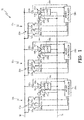
- FIG. 2 is a circuit diagram illustrating a system 110 for sensing current in solid state power controllers 112a-112n using shared current source 120 for all solid state power controllers 112a-112n.
- Solid state power controllers 112a-112n operate in the same manner as solid state power controllers 12a-12n of FIG. 1 except that they share current source 120 and current sensor 124 instead of each having individual current sources 20a-20n and current sensors 24a-24n.
- Current source 120 and current sensor 124 operate in the same manner as current source 20a and current sensor 24a of FIG. 1 . Because it is unlikely to have overload conditions in multiple loads 114a-114n at the same time, by only including one shared current source 120 and current sensor 124, the size of each solid state power controller 112a-112n can be reduced.
- a power controller controls power to a load and includes, among other things, a primary current sensor, a controller and a current source.
- the primary current sensor includes a primary conductor and an auxiliary conductor.
- the primary conductor carries a primary current to the load and the auxiliary conductor carries an auxiliary current in the opposite direction of the primary current to provide partial flux cancellation.
- the primary current sensor provides an output voltage based upon a magnetic field generated by the primary current and auxiliary current.
- the controller determines the primary current based upon the output voltage and the auxiliary current.
- the current source provides the auxiliary current.
- the controller controls the current source to provide the auxiliary current to the auxiliary conductor if the primary current is greater than a threshold value.
- the power controller of the preceding paragraph can optionally include, additionally and/or alternatively, any one or more of the following features, configurations and/or additional components:
- An auxiliary current sensor that senses the auxiliary current and provides a sensed auxiliary current value to the controller.
- the primary current sensor and auxiliary current sensor are Hall effect sensors.
- the current source includes a first switch enabled to provide a first magnitude current from a power bus.
- the auxiliary current is equal to the first magnitude current.
- the current source further includes a second switch enabled to provide a second magnitude current that is less than the first magnitude current.
- the auxiliary current is equal to the second magnitude current.
- the controller controls the power switch to control power to the first load based upon the primary current.
- the auxiliary conductor is an auxiliary winding having multiple turns.
- a method includes, among other things: providing a first output voltage from a primary current sensor that includes a primary conductor and an auxiliary conductor.
- the primary conductor carries a primary current to a load and the auxiliary conductor carries zero current.
- the first output voltage is directly proportional to the primary current.
- the method further includes determining if the primary current is greater than a threshold value based upon the first output voltage, and controlling a current source to provide an auxiliary current to the auxiliary conductor of the primary current sensor if the primary current is greater than the threshold value.
- the auxiliary current is in the opposite direction of the primary current to provide partial flux cancellation for the current sensor.
- the method further includes providing a second output voltage from the primary current sensor based upon the primary current and the auxiliary current, and determining the primary current to the load based upon the second output voltage and the auxiliary current.
- the method of the preceding paragraph can optionally include, additionally and/or alternatively, any one or more of the following features, configurations and/or additional components:
- the auxiliary conductor of the primary current sensor is an auxiliary winding that includes multiple turns.
- the method further includes controlling a power switch to control power to a load based upon the primary current.
- Determining the primary current to the load based upon the second output voltage includes providing a third output voltage from an auxiliary current sensor that is directly proportional to the auxiliary current.
- the primary current sensor and the auxiliary current sensor are Hall effect sensors.
- a system includes, among other things: a plurality of power controllers that control power to respective loads, and a current source.
- Each of the plurality of power controllers includes a primary current sensor and a controller.
- the primary current sensor includes a primary conductor and an auxiliary conductor.
- the primary conductor carries a primary current to the respective load and the auxiliary conductor carries an auxiliary current in the opposite direction of the primary current to provide partial flux cancellation.
- the primary current sensor provides an output voltage based upon a magnetic field generated by the primary current and auxiliary current.
- the controller determines the primary current based upon the output voltage and the auxiliary current.
- the current source is controlled by the controllers of the power controllers to provide the auxiliary current to the auxiliary conductors of the primary current sensors of the plurality of power controllers.
- the system of the preceding paragraph can optionally include, additionally and/or alternatively, any one or more of the following features, configurations and/or additional components:
- the plurality of power controllers each further include a power switch.
- the controller controls the power switch to control power to the respective load based upon the primary current.
- the auxiliary conductors of the primary current sensors of the plurality of power controllers are auxiliary windings having multiple turns.
Landscapes
- Engineering & Computer Science (AREA)
- Power Engineering (AREA)
- Physics & Mathematics (AREA)
- General Physics & Mathematics (AREA)
- Measuring Instrument Details And Bridges, And Automatic Balancing Devices (AREA)
- Emergency Protection Circuit Devices (AREA)
Description
- Solid state power controllers (SSPCs) are often used in power distribution systems to protect electrical systems from overload conditions. SSPCs often employ I2t over-current protection. I2t protection allows over-currents for a short amount of time based upon a threshold power flow. These over-currents may be, for example, 800% to 1000% of the steady-state current. Because of this, the SSPCs are required to have a high accuracy current sensor with a wide measuring range. For example, if a steady-state current is 200 amps, the current sensor must be able to accurately sense up to 2000 amps.
- In the past, resistive shunts and Hall effect sensors have been used for current sensing in SSPCs. Resistive shunts, however, have power losses that can be quite high when required to support large over-currents. Hall effect sensors are non-contact sensors that sense current based upon a magnetic field created by current flowing in a conductor. These sensors include a core that is implemented around the conductor in which most of the magnetic field generated by the current is concentrated. The core includes an air gap, with a Hall effect device mounted in the air gap of the core at a right angle to the concentrated magnetic field. The Hall effect device produces a voltage that is proportional to the current in the conductor. The larger the current in the conductor, the larger the size of the Hall effect sensor that is required in order to provide accurate measurements. It is desirable to limit the size of these current sensors in order to reduce the size and weight of the SSPC.
InU.S. 5,150,270 , a transformer circuit is disclosed that includes a primary winding, a sense winding, and a feedback winding. The sense winding is included to sense the magnetic flux of the transformer core, and the feedback winding is included to adjust the magnetic flux of the transformer core. - A power controller controls power to a load and includes a primary current sensor, a controller and a current source. The primary current sensor includes a primary conductor and an auxiliary conductor. The primary conductor carries a primary current to the load and the auxiliary conductor carries an auxiliary current in the opposite direction of the primary current to provide partial flux cancellation. The primary current sensor provides an output voltage based upon a magnetic field generated by the primary current and auxiliary current. The controller determines the primary current based upon the output voltage and the auxiliary current. The current source provides the auxiliary current. The controller controls the current source to provide the auxiliary current to the auxiliary conductor if the primary current is greater than a threshold value.
- The invention is defined in the appended claims.
-
-
FIG. 1 is a circuit diagram illustrating a system for sensing current in solid state power controllers using partial flux cancellation for extended measuring range. -
FIG. 2 is a circuit diagram illustrating a system for sensing current in solid state power controllers using a shared current source for all solid state power controllers. - A solid state power controller (SSPC) is disclosed herein that utilizes a current sensor with an auxiliary winding for partial flux cancellation for extended measuring range. Each SSPC includes a primary current sensor and controller utilized to monitor for overload conditions and control power to a respective load. The primary current sensor, which may be a Hall effect sensor, includes a primary conductor and an auxiliary conductor. The primary conductor carries a primary current to the load and the auxiliary conductor receives an auxiliary current from a current source in the opposite direction of the primary current to provide partial flux cancellation. The auxiliary conductor may be implemented as a winding with multiple turns to provide greater flux cancellation for a given magnitude of auxiliary current. During steady-state conditions, no auxiliary current is provided to the auxiliary conductor and the output voltage from the sensor is directly proportional to the primary current. When an over-current of, for example, 200% to 1000% of the steady-state current is detected, the current source is controlled by the controller to provide the auxiliary current to the auxiliary conductor of the current sensor. This provides partial flux cancellation for the magnetic core of the sensor, which prevents saturation of core for larger primary currents. When receiving the auxiliary current, the output voltage of the sensor is decreased for a given primary current due to the partial flux cancellation. When auxiliary current is being provided to the auxiliary winding, the microcontroller can determine the primary current based upon the Hall voltage and the magnitude of the auxiliary current. The auxiliary current may be determined by the controller, or may be sensed using an auxiliary current sensor. This way, the primary current can be accurately sensed for both steady-state currents and over-currents using a smaller current sensor than would be necessary without the auxiliary winding.
-
FIG. 1 is a circuit diagramillustrating system 10 for sensing current inSSPCs 12a-12n using partial flux cancellation for extended measuring range.System 10 includesloads 14a-14n,positive rail 16, andnegative rail 18.Positive rail 16 andnegative rail 18 receive power from any DC power source.System 10 may include any number ofSSPCs 12a-12n andloads 14a-14n. SSPC 12a includescurrent source 20a,current sensors auxiliary winding 26a,microcontroller 28a, andswitch 30a. SSPC 12b includescurrent source 20b,current sensors auxiliary winding 26b,microcontroller 28b, andswitch 30b. SSPC 12n includescurrent source 20n,current sensors auxiliary winding 26n,microcontroller 28n, andswitch 30n.Switches 30a-30n may be any known power switches, such as power metal-oxide-semiconductor field-effect transistors (MOSFETs).Current sensor 22a includes core 44a andHall effect device 46a.Current sensor 22b includescore 44b andHall effect device 46b, andcurrent sensor 22n includescore 44n andHall effect device 46n.Current source 20a includesresistors Current source 20b includesresistors Current source 20n includesresistors switches -
Current sensor 22a senses current to load 14a to monitor, for example, for overload conditions. Because the current during overload conditions may be, for example, 200% to 1000% of the steady-state current,sensor 22a is implemented to accurately sense current both within this range, as well as during steady-state conditions.Current sensor 22a is any current sensor that senses current based upon a magnetic field generated by the current, such as a Hall effect sensor. Hall effect sensors provide an output voltage fromHall effect device 46a directly proportional to the current flowing through the Hall effect sensor based upon a concentrated magnetic field in core 44a.Current sensor 22a provides the output voltage tomicrocontroller 28a. -
Current sensor 22a includesauxiliary winding 26a which provides partial flux cancellation forcurrent sensor 22a. Becausecurrent sensor 22a senses current based upon the magnetic field generated by the primary current to load 14a, partial flux cancellation is achieved by providing current toauxiliary winding 26a in the opposite direction of the primary current to load 14a. This reduces the magnitude of the magnetic field concentrated in magnetic core 44a ofcurrent sensor 22a for a given primary current to load 14a. The amount of partial flux cancellation is based upon both the magnitude of the auxiliary current in winding 26a and the number of turns ofauxiliary winding 26a. -
Auxiliary winding 26a receives no current when the primary current to load 14a is less than a threshold value. This threshold value may be, for example, 200% of the steady-state current. When no current is being provided to auxiliary winding 26a,microcontroller 28a determines the current to load 14a based upon the provided output voltage ofcurrent sensor 22a. When the determined current is greater than the threshold value,microcontroller 28a controlscurrent source 20a to enable current to auxiliary winding 26a. In the present embodiment,microcontroller 28a can enable switches 38a, 40a, and 42a separately to vary the current fromcurrent source 20a depending upon the desired auxiliary current. Enabling switch 38a provides a path to ground throughonly resistor 32a, which creates the greatest possible current to auxiliary winding 26a. Enabling only switch 40a provides a path to ground through bothresistors resistors Microcontroller 28a enables switches 38a, 40a, and 42a to provide a desired current based upon the determined current fromcurrent sensor 22a. Switches 38a, 40a, and 42a are any known switches such as, for example, insulated gate bipolar transistors (IGBTs). - Because the partial flux cancellation decreases the output voltage of
current sensor 22a without decreasing the current to load 14a, the current to load 14a is determined using the output voltage fromcurrent sensor 22a as well as the auxiliary current fromcurrent source 20a and the number of turns of auxiliary winding 26a. The primary current to load 14a may be determined bymicrocontroller 28a using either a closed loop or an open loop approach. If using an open loop approach,microcontroller 28a determines the current to auxiliary winding 26a according to the following equation:
- Where:
- IP = primary current to load 14a.
- kH = sensor gain of
current sensor 22a (volts/amp). - VH = Hall voltage provided by
current sensor 22a. - IA = current to auxiliary winding 26a determined below using Table 1.
- n = number of turns in auxiliary winding 26a.
-
Microcontroller 28a determines the current to auxiliary winding 26a using known values withincurrent source 20a.Current sensor 24a is not necessary when using the open loop approach becausemicrocontroller 28a determines the auxiliary current based upon known values withinsystem 10. The following table shows the equations used to determine the auxiliary current based upon the switch states of switches 38a, 40a, and 42a ofcurrent source 20a:(Table 1) S3 S2 S1 IA 0 0 0 0 0 0 1 
0 1 0 
0 1 1 
1 0 0 
1 0 1 
1 1 0 
1 1 1 
Where:
VDC = bus voltage onpositive rail 16.
R1, R2 , and R3 = resistance ofresistors
S1, S2, and S3 = switching states of transistors 38a, 40a, and 42a respectively (1: conducting; 0: not conducting). - A closed loop approach may also be implemented by
microcontroller 28a to determine the primary current to load 14a. In this embodiment,current sensor 24a is used to sense the auxiliary current to winding 26a.Current sensor 24a provides an output voltage tomicrocontroller 28a directly proportional to the current to auxiliary winding 26a.Microcontroller 28a then determines the primary current using the following equation:
- Where:
- IP = primary current to load 14a.
- kH = sensor gain of
current sensor 22a (volts/amp). - VH = Hall voltage provided by
current sensor 22a. - kA = sensor gain of
current sensor 24a (volts/amp). - VA = Hall voltage provided by
current sensor 24a. - n = number of turns in auxiliary winding 26a.
-
Microcontroller 28a controlspower switch 30a based upon the determined primary current to load 14a.Microcontroller 28a may implement, for example, I2t protection. If the power flow over time reaches a threshold value, microcontroller can turn offpower switch 30a to stop power flow to load 14a.SSPCs 12b-12n operate in the same manner asSSPC 12a and are therefore not described herein. -
FIG. 2 is a circuit diagram illustrating asystem 110 for sensing current in solidstate power controllers 112a-112n using sharedcurrent source 120 for all solidstate power controllers 112a-112n. Solidstate power controllers 112a-112n operate in the same manner as solidstate power controllers 12a-12n ofFIG. 1 except that they sharecurrent source 120 andcurrent sensor 124 instead of each having individualcurrent sources 20a-20n andcurrent sensors 24a-24n.Current source 120 andcurrent sensor 124 operate in the same manner ascurrent source 20a andcurrent sensor 24a ofFIG. 1 . Because it is unlikely to have overload conditions inmultiple loads 114a-114n at the same time, by only including one sharedcurrent source 120 andcurrent sensor 124, the size of each solidstate power controller 112a-112n can be reduced. - The following are non-exclusive descriptions of possible embodiments of the present invention.
- A power controller controls power to a load and includes, among other things, a primary current sensor, a controller and a current source. The primary current sensor includes a primary conductor and an auxiliary conductor. The primary conductor carries a primary current to the load and the auxiliary conductor carries an auxiliary current in the opposite direction of the primary current to provide partial flux cancellation. The primary current sensor provides an output voltage based upon a magnetic field generated by the primary current and auxiliary current. The controller determines the primary current based upon the output voltage and the auxiliary current. The current source provides the auxiliary current. The controller controls the current source to provide the auxiliary current to the auxiliary conductor if the primary current is greater than a threshold value.
- The power controller of the preceding paragraph can optionally include, additionally and/or alternatively, any one or more of the following features, configurations and/or additional components:
- An auxiliary current sensor that senses the auxiliary current and provides a sensed auxiliary current value to the controller.
- The primary current sensor and auxiliary current sensor are Hall effect sensors.
- The current source includes a first switch enabled to provide a first magnitude current from a power bus. The auxiliary current is equal to the first magnitude current.
- The current source further includes a second switch enabled to provide a second magnitude current that is less than the first magnitude current. The auxiliary current is equal to the second magnitude current.
- A power switch. The controller controls the power switch to control power to the first load based upon the primary current.
- The auxiliary conductor is an auxiliary winding having multiple turns.
- A method includes, among other things: providing a first output voltage from a primary current sensor that includes a primary conductor and an auxiliary conductor. The primary conductor carries a primary current to a load and the auxiliary conductor carries zero current. The first output voltage is directly proportional to the primary current. The method further includes determining if the primary current is greater than a threshold value based upon the first output voltage, and controlling a current source to provide an auxiliary current to the auxiliary conductor of the primary current sensor if the primary current is greater than the threshold value. The auxiliary current is in the opposite direction of the primary current to provide partial flux cancellation for the current sensor. The method further includes providing a second output voltage from the primary current sensor based upon the primary current and the auxiliary current, and determining the primary current to the load based upon the second output voltage and the auxiliary current.
- The method of the preceding paragraph can optionally include, additionally and/or alternatively, any one or more of the following features, configurations and/or additional components:
The auxiliary conductor of the primary current sensor is an auxiliary winding that includes multiple turns. - The method further includes controlling a power switch to control power to a load based upon the primary current.
- Determining the primary current to the load based upon the second output voltage includes providing a third output voltage from an auxiliary current sensor that is directly proportional to the auxiliary current.
- The primary current sensor and the auxiliary current sensor are Hall effect sensors.
- A system includes, among other things: a plurality of power controllers that control power to respective loads, and a current source. Each of the plurality of power controllers includes a primary current sensor and a controller. The primary current sensor includes a primary conductor and an auxiliary conductor. The primary conductor carries a primary current to the respective load and the auxiliary conductor carries an auxiliary current in the opposite direction of the primary current to provide partial flux cancellation. The primary current sensor provides an output voltage based upon a magnetic field generated by the primary current and auxiliary current. The controller determines the primary current based upon the output voltage and the auxiliary current. The current source is controlled by the controllers of the power controllers to provide the auxiliary current to the auxiliary conductors of the primary current sensors of the plurality of power controllers.
- The system of the preceding paragraph can optionally include, additionally and/or alternatively, any one or more of the following features, configurations and/or additional components:
- An auxiliary current sensor that senses the auxiliary current from the current source.
- The plurality of power controllers each further include a power switch. The controller controls the power switch to control power to the respective load based upon the primary current.
- The auxiliary conductors of the primary current sensors of the plurality of power controllers are auxiliary windings having multiple turns.
- While the invention has been described with reference to an exemplary embodiment(s), it will be understood by those skilled in the art that various changes may be made and equivalents may be substituted for elements thereof without departing from the scope of the invention. In addition, many modifications may be made to adapt a particular situation or material to the teachings of the invention without departing from the essential scope thereof. Therefore, it is intended that the invention not be limited to the particular embodiment(s) disclosed, but that the invention will include all embodiments falling within the scope of the appended claims.
Claims (14)
- A power controller that controls power to a load, the power controller comprising:a primary current sensor (22a) that includes a primary conductor and an auxiliary conductor (26a), wherein the primary conductor is arranged to carry a primary current to the load (14a) and the auxiliary conductor is arranged to carry an auxiliary current in the opposite direction of the primary current to provide partial flux cancellation, and wherein the primary current sensor is configured to provide an output voltage based upon a magnetic field generated by the primary current and auxiliary current;a controller (28a) configured to determine the primary current based upon the output voltage and the auxiliary current; anda current source (20a) configured to provide the auxiliary current; characterised in that the controller is configured to control the current source to provide the auxiliary current to the auxiliary conductor if the primary current is greater than a threshold value.
- The power controller of claim 1, further comprising an auxiliary current sensor (24a) configured to sense the auxiliary current and to provide a sensed auxiliary current value to the controller.
- The power controller of claim 2, wherein the primary current sensor and auxiliary current sensor are Hall effect sensors.
- The power controller of any preceding claim, wherein the current source comprises a first switch (38a) enabled to provide a first magnitude current from a power bus, wherein the auxiliary current is equal to the first magnitude current.
- The power controller of claim 4, wherein the current source further comprises a second switch (40a) enabled to provide a second magnitude current that is less than the first magnitude current, wherein the auxiliary current is equal to the second magnitude current.
- The power controller of any preceding claim, further comprising a power switch (30a), wherein the controller is configured to control the power switch to control power to the first load based upon the primary current.
- The power controller of any preceding claim, wherein the auxiliary conductor is an auxiliary winding having multiple turns.
- A method comprising:providing a first output voltage from a primary current sensor that includes a primary conductor that carries a primary current to a load, and an auxiliary conductor that carries zero current, wherein the first output voltage is directly proportional to the primary current; anddetermining if the primary current is greater than a threshold value based upon the first output voltage; characterised bycontrolling a current source to provide an auxiliary current to the auxiliary conductor of the primary current sensor if the primary current is greater than the threshold value, wherein the auxiliary current is in the opposite direction of the primary current to provide partial flux cancellation for the current sensor;providing a second output voltage from the primary current sensor based upon the primary current and the auxiliary current; anddetermining the primary current to the load based upon the second output voltage and the auxiliary current.
- The method of claim 8, wherein the auxiliary conductor of the primary current sensor is an auxiliary winding that includes multiple turns.
- The method of claim 8, further comprising controlling a power switch to control power to a load based upon the primary current.
- The method of claim 8, wherein determining the primary current to the load based upon the second output voltage comprises providing a third output voltage from an auxiliary current sensor that is directly proportional to the auxiliary current.
- The method of claim 11, wherein the primary current sensor and the auxiliary current sensor are Hall effect sensors.
- A system comprising:a plurality of said power controllers of any of claims 1 to 7 that control power to respective loads, each of the plurality of power controllers comprising:a primary current sensor that includes a primary conductor and an auxiliary conductor, wherein the primary conductor carries a primary current to the respective load and the auxiliary conductor carries an auxiliary current in the opposite direction of the primary current to provide partial flux cancellation, and wherein the primary current sensor provides an output voltage based upon a magnetic field generated by the primary current and auxiliary current; anda controller that determines the primary current based upon the output voltage and the auxiliary current; anda current source controlled by the controllers of the plurality of power controllers to provide the auxiliary current to the auxiliary conductors of the primary current sensors of the plurality of power controllers.
- The system of claim 13, further comprising an auxiliary current sensor that senses the auxiliary current from the current source.
Applications Claiming Priority (1)
| Application Number | Priority Date | Filing Date | Title |
|---|---|---|---|
| US13/903,189 US9466983B2 (en) | 2013-05-28 | 2013-05-28 | Auxiliary winding for extended current measurement |
Publications (2)
| Publication Number | Publication Date |
|---|---|
| EP2808967A1 EP2808967A1 (en) | 2014-12-03 |
| EP2808967B1 true EP2808967B1 (en) | 2016-10-05 |
Family
ID=50828713
Family Applications (1)
| Application Number | Title | Priority Date | Filing Date |
|---|---|---|---|
| EP14169823.3A Active EP2808967B1 (en) | 2013-05-28 | 2014-05-26 | Auxiliary winding for extended current measurement |
Country Status (2)
| Country | Link |
|---|---|
| US (1) | US9466983B2 (en) |
| EP (1) | EP2808967B1 (en) |
Family Cites Families (17)
| Publication number | Priority date | Publication date | Assignee | Title |
|---|---|---|---|---|
| US4278940A (en) * | 1979-04-25 | 1981-07-14 | General Electric Company | Means for automatically compensating DC magnetization in a transformer |
| US4255705A (en) * | 1979-09-24 | 1981-03-10 | General Electric Company | Peak detection and electronic compensation of D. C. saturation magnetization in current transformers used in watt hour meter installations |
| US4914383A (en) | 1985-10-10 | 1990-04-03 | Wilkerson A W | Non-contact ammeter |
| US4847554A (en) * | 1987-03-04 | 1989-07-11 | Sangamo Weston, Inc. | Current measuring and magnetic core compensating apparatus and method |
| FR2645650B1 (en) * | 1989-04-06 | 1991-09-27 | Merlin Gerin | SYSTEM FOR CONTROLLING THE ISOLATION OF A DIRECT CURRENT NETWORK |
| US5150270A (en) * | 1991-03-01 | 1992-09-22 | Dowty Rfl Industries, Inc. | Transformer circuit and method with saturation prevention |
| FR2846749B1 (en) | 2002-11-04 | 2005-01-07 | Siemens Vdo Automotive | DEVICE FOR MEASURING THE INTENSITY OF AN ELECTRICAL CURRENT |
| US7400065B2 (en) | 2004-08-24 | 2008-07-15 | Honeywell International Inc. | Electrical power distribution system and method with active load control |
| US7242157B1 (en) * | 2005-02-11 | 2007-07-10 | Edel Thomas G | Switched-voltage control of the magnetization of current transforms and other magnetic bodies |
| US7834613B2 (en) * | 2007-10-30 | 2010-11-16 | Power-One, Inc. | Isolated current to voltage, voltage to voltage converter |
| US8390151B2 (en) | 2010-03-10 | 2013-03-05 | Hamilton Sundstrand Corporation | SSPC with active current limiting |
| US8536730B2 (en) | 2010-07-12 | 2013-09-17 | Hamilton Sundstrand Corporation | Electric power generating and distribution system comprising a decoupling filter and a solid state power controller |
| US8553373B2 (en) | 2011-08-25 | 2013-10-08 | Hamilton Sundstrand Corporation | Solid state power controller for high voltage direct current systems |
| US8912682B2 (en) | 2011-08-25 | 2014-12-16 | Hamilton Sundstrand Corporation | Power management and distribution center for constant power loads |
| US8625243B2 (en) | 2011-08-25 | 2014-01-07 | Hamilton Sundstrand Corporation | Multi-functional solid state power controller |
| US9188610B1 (en) * | 2012-01-18 | 2015-11-17 | Thomas G. Edel | Apparatus for measuring multiple electric currents utilizing multiple current transformers |
| US8787039B2 (en) * | 2012-07-18 | 2014-07-22 | Dialog Semiconductor Inc. | Hybrid adaptive power factor correction schemes for switching power converters |
-
2013
- 2013-05-28 US US13/903,189 patent/US9466983B2/en active Active
-
2014
- 2014-05-26 EP EP14169823.3A patent/EP2808967B1/en active Active
Also Published As
| Publication number | Publication date |
|---|---|
| US20140354049A1 (en) | 2014-12-04 |
| EP2808967A1 (en) | 2014-12-03 |
| US9466983B2 (en) | 2016-10-11 |
Similar Documents
| Publication | Publication Date | Title |
|---|---|---|
| US20100001716A1 (en) | Direct Current Measuring Device With Wide Measuring Range, Electro-Technical Unit Comprising One Such Measuring Device and Switchgear Unit Having One Such Electro-Technical Unit | |
| CN104422810B (en) | Current measurement circuit | |
| US9304152B2 (en) | Current monitoring circuits and methods | |
| US20150346245A1 (en) | Current or voltage sensing | |
| US9529016B2 (en) | Current monitoring circuits and methods and transistor arrangement | |
| US9188610B1 (en) | Apparatus for measuring multiple electric currents utilizing multiple current transformers | |
| DE102017122765A1 (en) | SYSTEM AND METHOD FOR A DETECTOR FOR TOO HIGH PERFORMANCE | |
| US5202621A (en) | Current transformer arrangement for three-wire three-phase systems to detect the actual current value for controlled dc loads powered via power converters | |
| JP2017529776A (en) | Electronic circuit breaker | |
| EP3179257B1 (en) | Precise current measurement with chopping technique for high power driver | |
| US10031162B2 (en) | Current detection device and method for sensing an electric current | |
| EP2808967B1 (en) | Auxiliary winding for extended current measurement | |
| EP2806278B1 (en) | Current divider for extended current measurement | |
| US3683237A (en) | Adjustable solid state overload relay | |
| US10605873B2 (en) | Apparatus for monitoring a magnetic core and method for detecting a saturation behavior of a magnetic core to be monitored | |
| US20170070056A1 (en) | Power control current sharing circuit | |
| EP3557730A1 (en) | Power network device | |
| DE19748550A1 (en) | Method for measuring electrical currents in n conductors and device for carrying out the method | |
| US20150022175A1 (en) | Voltage limiter and use of a voltage limiter to determine values of a power semiconductor element | |
| MX2019000605A (en) | Electronic overload breaker with built-in shunt calibration (bisc) and methods of operating same. | |
| US20180183334A1 (en) | Reversible electronic circuit-breaker terminal | |
| Chen et al. | A new type of hall current sensor | |
| US20140333300A1 (en) | Regulated magnetic flux density for extended current measurement | |
| KR20150108268A (en) | Current measuring device and operating method thereof | |
| KR102164860B1 (en) | Protection Device of Overvoltage or Overcurrent on Isolated Converter |
Legal Events
| Date | Code | Title | Description |
|---|---|---|---|
| PUAI | Public reference made under article 153(3) epc to a published international application that has entered the european phase |
Free format text: ORIGINAL CODE: 0009012 |
|
| 17P | Request for examination filed |
Effective date: 20140526 |
|
| AK | Designated contracting states |
Kind code of ref document: A1 Designated state(s): AL AT BE BG CH CY CZ DE DK EE ES FI FR GB GR HR HU IE IS IT LI LT LU LV MC MK MT NL NO PL PT RO RS SE SI SK SM TR |
|
| AX | Request for extension of the european patent |
Extension state: BA ME |
|
| R17P | Request for examination filed (corrected) |
Effective date: 20150528 |
|
| RBV | Designated contracting states (corrected) |
Designated state(s): AL AT BE BG CH CY CZ DE DK EE ES FI FR GB GR HR HU IE IS IT LI LT LU LV MC MK MT NL NO PL PT RO RS SE SI SK SM TR |
|
| GRAP | Despatch of communication of intention to grant a patent |
Free format text: ORIGINAL CODE: EPIDOSNIGR1 |
|
| RIC1 | Information provided on ipc code assigned before grant |
Ipc: H02H 1/00 20060101AFI20160405BHEP Ipc: H02H 3/08 20060101ALI20160405BHEP Ipc: G01R 15/00 20060101ALI20160405BHEP |
|
| INTG | Intention to grant announced |
Effective date: 20160419 |
|
| GRAS | Grant fee paid |
Free format text: ORIGINAL CODE: EPIDOSNIGR3 |
|
| GRAA | (expected) grant |
Free format text: ORIGINAL CODE: 0009210 |
|
| AK | Designated contracting states |
Kind code of ref document: B1 Designated state(s): AL AT BE BG CH CY CZ DE DK EE ES FI FR GB GR HR HU IE IS IT LI LT LU LV MC MK MT NL NO PL PT RO RS SE SI SK SM TR |
|
| REG | Reference to a national code |
Ref country code: GB Ref legal event code: FG4D |
|
| REG | Reference to a national code |
Ref country code: CH Ref legal event code: EP |
|
| REG | Reference to a national code |
Ref country code: AT Ref legal event code: REF Ref document number: 835363 Country of ref document: AT Kind code of ref document: T Effective date: 20161015 |
|
| REG | Reference to a national code |
Ref country code: IE Ref legal event code: FG4D |
|
| REG | Reference to a national code |
Ref country code: DE Ref legal event code: R096 Ref document number: 602014004038 Country of ref document: DE |
|
| REG | Reference to a national code |
Ref country code: NL Ref legal event code: MP Effective date: 20161005 |
|
| REG | Reference to a national code |
Ref country code: LT Ref legal event code: MG4D |
|
| PG25 | Lapsed in a contracting state [announced via postgrant information from national office to epo] |
Ref country code: LV Free format text: LAPSE BECAUSE OF FAILURE TO SUBMIT A TRANSLATION OF THE DESCRIPTION OR TO PAY THE FEE WITHIN THE PRESCRIBED TIME-LIMIT Effective date: 20161005 |
|
| REG | Reference to a national code |
Ref country code: AT Ref legal event code: MK05 Ref document number: 835363 Country of ref document: AT Kind code of ref document: T Effective date: 20161005 |
|
| REG | Reference to a national code |
Ref country code: FR Ref legal event code: PLFP Year of fee payment: 4 |
|
| PG25 | Lapsed in a contracting state [announced via postgrant information from national office to epo] |
Ref country code: GR Free format text: LAPSE BECAUSE OF FAILURE TO SUBMIT A TRANSLATION OF THE DESCRIPTION OR TO PAY THE FEE WITHIN THE PRESCRIBED TIME-LIMIT Effective date: 20170106 Ref country code: SE Free format text: LAPSE BECAUSE OF FAILURE TO SUBMIT A TRANSLATION OF THE DESCRIPTION OR TO PAY THE FEE WITHIN THE PRESCRIBED TIME-LIMIT Effective date: 20161005 Ref country code: NO Free format text: LAPSE BECAUSE OF FAILURE TO SUBMIT A TRANSLATION OF THE DESCRIPTION OR TO PAY THE FEE WITHIN THE PRESCRIBED TIME-LIMIT Effective date: 20170105 Ref country code: LT Free format text: LAPSE BECAUSE OF FAILURE TO SUBMIT A TRANSLATION OF THE DESCRIPTION OR TO PAY THE FEE WITHIN THE PRESCRIBED TIME-LIMIT Effective date: 20161005 |
|
| PG25 | Lapsed in a contracting state [announced via postgrant information from national office to epo] |
Ref country code: IS Free format text: LAPSE BECAUSE OF FAILURE TO SUBMIT A TRANSLATION OF THE DESCRIPTION OR TO PAY THE FEE WITHIN THE PRESCRIBED TIME-LIMIT Effective date: 20170205 Ref country code: PT Free format text: LAPSE BECAUSE OF FAILURE TO SUBMIT A TRANSLATION OF THE DESCRIPTION OR TO PAY THE FEE WITHIN THE PRESCRIBED TIME-LIMIT Effective date: 20170206 Ref country code: BE Free format text: LAPSE BECAUSE OF FAILURE TO SUBMIT A TRANSLATION OF THE DESCRIPTION OR TO PAY THE FEE WITHIN THE PRESCRIBED TIME-LIMIT Effective date: 20161005 Ref country code: HR Free format text: LAPSE BECAUSE OF FAILURE TO SUBMIT A TRANSLATION OF THE DESCRIPTION OR TO PAY THE FEE WITHIN THE PRESCRIBED TIME-LIMIT Effective date: 20161005 Ref country code: RS Free format text: LAPSE BECAUSE OF FAILURE TO SUBMIT A TRANSLATION OF THE DESCRIPTION OR TO PAY THE FEE WITHIN THE PRESCRIBED TIME-LIMIT Effective date: 20161005 Ref country code: NL Free format text: LAPSE BECAUSE OF FAILURE TO SUBMIT A TRANSLATION OF THE DESCRIPTION OR TO PAY THE FEE WITHIN THE PRESCRIBED TIME-LIMIT Effective date: 20161005 Ref country code: FI Free format text: LAPSE BECAUSE OF FAILURE TO SUBMIT A TRANSLATION OF THE DESCRIPTION OR TO PAY THE FEE WITHIN THE PRESCRIBED TIME-LIMIT Effective date: 20161005 Ref country code: AT Free format text: LAPSE BECAUSE OF FAILURE TO SUBMIT A TRANSLATION OF THE DESCRIPTION OR TO PAY THE FEE WITHIN THE PRESCRIBED TIME-LIMIT Effective date: 20161005 Ref country code: ES Free format text: LAPSE BECAUSE OF FAILURE TO SUBMIT A TRANSLATION OF THE DESCRIPTION OR TO PAY THE FEE WITHIN THE PRESCRIBED TIME-LIMIT Effective date: 20161005 Ref country code: PL Free format text: LAPSE BECAUSE OF FAILURE TO SUBMIT A TRANSLATION OF THE DESCRIPTION OR TO PAY THE FEE WITHIN THE PRESCRIBED TIME-LIMIT Effective date: 20161005 |
|
| REG | Reference to a national code |
Ref country code: DE Ref legal event code: R097 Ref document number: 602014004038 Country of ref document: DE |
|
| PG25 | Lapsed in a contracting state [announced via postgrant information from national office to epo] |
Ref country code: EE Free format text: LAPSE BECAUSE OF FAILURE TO SUBMIT A TRANSLATION OF THE DESCRIPTION OR TO PAY THE FEE WITHIN THE PRESCRIBED TIME-LIMIT Effective date: 20161005 Ref country code: SK Free format text: LAPSE BECAUSE OF FAILURE TO SUBMIT A TRANSLATION OF THE DESCRIPTION OR TO PAY THE FEE WITHIN THE PRESCRIBED TIME-LIMIT Effective date: 20161005 Ref country code: DK Free format text: LAPSE BECAUSE OF FAILURE TO SUBMIT A TRANSLATION OF THE DESCRIPTION OR TO PAY THE FEE WITHIN THE PRESCRIBED TIME-LIMIT Effective date: 20161005 Ref country code: RO Free format text: LAPSE BECAUSE OF FAILURE TO SUBMIT A TRANSLATION OF THE DESCRIPTION OR TO PAY THE FEE WITHIN THE PRESCRIBED TIME-LIMIT Effective date: 20161005 Ref country code: CZ Free format text: LAPSE BECAUSE OF FAILURE TO SUBMIT A TRANSLATION OF THE DESCRIPTION OR TO PAY THE FEE WITHIN THE PRESCRIBED TIME-LIMIT Effective date: 20161005 |
|
| PLBE | No opposition filed within time limit |
Free format text: ORIGINAL CODE: 0009261 |
|
| STAA | Information on the status of an ep patent application or granted ep patent |
Free format text: STATUS: NO OPPOSITION FILED WITHIN TIME LIMIT |
|
| PG25 | Lapsed in a contracting state [announced via postgrant information from national office to epo] |
Ref country code: IT Free format text: LAPSE BECAUSE OF FAILURE TO SUBMIT A TRANSLATION OF THE DESCRIPTION OR TO PAY THE FEE WITHIN THE PRESCRIBED TIME-LIMIT Effective date: 20161005 Ref country code: LU Free format text: LAPSE BECAUSE OF NON-PAYMENT OF DUE FEES Effective date: 20170531 Ref country code: BG Free format text: LAPSE BECAUSE OF FAILURE TO SUBMIT A TRANSLATION OF THE DESCRIPTION OR TO PAY THE FEE WITHIN THE PRESCRIBED TIME-LIMIT Effective date: 20170105 Ref country code: SM Free format text: LAPSE BECAUSE OF FAILURE TO SUBMIT A TRANSLATION OF THE DESCRIPTION OR TO PAY THE FEE WITHIN THE PRESCRIBED TIME-LIMIT Effective date: 20161005 |
|
| 26N | No opposition filed |
Effective date: 20170706 |
|
| PG25 | Lapsed in a contracting state [announced via postgrant information from national office to epo] |
Ref country code: SI Free format text: LAPSE BECAUSE OF FAILURE TO SUBMIT A TRANSLATION OF THE DESCRIPTION OR TO PAY THE FEE WITHIN THE PRESCRIBED TIME-LIMIT Effective date: 20161005 |
|
| REG | Reference to a national code |
Ref country code: CH Ref legal event code: PL |
|
| PG25 | Lapsed in a contracting state [announced via postgrant information from national office to epo] |
Ref country code: MC Free format text: LAPSE BECAUSE OF FAILURE TO SUBMIT A TRANSLATION OF THE DESCRIPTION OR TO PAY THE FEE WITHIN THE PRESCRIBED TIME-LIMIT Effective date: 20161005 |
|
| REG | Reference to a national code |
Ref country code: IE Ref legal event code: MM4A |
|
| PG25 | Lapsed in a contracting state [announced via postgrant information from national office to epo] |
Ref country code: CH Free format text: LAPSE BECAUSE OF NON-PAYMENT OF DUE FEES Effective date: 20170531 Ref country code: LI Free format text: LAPSE BECAUSE OF NON-PAYMENT OF DUE FEES Effective date: 20170531 |
|
| PG25 | Lapsed in a contracting state [announced via postgrant information from national office to epo] |
Ref country code: LU Free format text: LAPSE BECAUSE OF NON-PAYMENT OF DUE FEES Effective date: 20170526 |
|
| REG | Reference to a national code |
Ref country code: FR Ref legal event code: PLFP Year of fee payment: 5 |
|
| PG25 | Lapsed in a contracting state [announced via postgrant information from national office to epo] |
Ref country code: IE Free format text: LAPSE BECAUSE OF NON-PAYMENT OF DUE FEES Effective date: 20170526 |
|
| PG25 | Lapsed in a contracting state [announced via postgrant information from national office to epo] |
Ref country code: MT Free format text: LAPSE BECAUSE OF NON-PAYMENT OF DUE FEES Effective date: 20170526 |
|
| PG25 | Lapsed in a contracting state [announced via postgrant information from national office to epo] |
Ref country code: HU Free format text: LAPSE BECAUSE OF FAILURE TO SUBMIT A TRANSLATION OF THE DESCRIPTION OR TO PAY THE FEE WITHIN THE PRESCRIBED TIME-LIMIT; INVALID AB INITIO Effective date: 20140526 |
|
| PG25 | Lapsed in a contracting state [announced via postgrant information from national office to epo] |
Ref country code: CY Free format text: LAPSE BECAUSE OF FAILURE TO SUBMIT A TRANSLATION OF THE DESCRIPTION OR TO PAY THE FEE WITHIN THE PRESCRIBED TIME-LIMIT Effective date: 20161005 |
|
| PG25 | Lapsed in a contracting state [announced via postgrant information from national office to epo] |
Ref country code: MK Free format text: LAPSE BECAUSE OF FAILURE TO SUBMIT A TRANSLATION OF THE DESCRIPTION OR TO PAY THE FEE WITHIN THE PRESCRIBED TIME-LIMIT Effective date: 20161005 |
|
| PG25 | Lapsed in a contracting state [announced via postgrant information from national office to epo] |
Ref country code: TR Free format text: LAPSE BECAUSE OF FAILURE TO SUBMIT A TRANSLATION OF THE DESCRIPTION OR TO PAY THE FEE WITHIN THE PRESCRIBED TIME-LIMIT Effective date: 20161005 |
|
| PG25 | Lapsed in a contracting state [announced via postgrant information from national office to epo] |
Ref country code: AL Free format text: LAPSE BECAUSE OF FAILURE TO SUBMIT A TRANSLATION OF THE DESCRIPTION OR TO PAY THE FEE WITHIN THE PRESCRIBED TIME-LIMIT Effective date: 20161005 |
|
| REG | Reference to a national code |
Ref country code: DE Ref legal event code: R082 Ref document number: 602014004038 Country of ref document: DE |
|
| P01 | Opt-out of the competence of the unified patent court (upc) registered |
Effective date: 20230522 |
|
| PGFP | Annual fee paid to national office [announced via postgrant information from national office to epo] |
Ref country code: FR Payment date: 20230420 Year of fee payment: 10 Ref country code: DE Payment date: 20230419 Year of fee payment: 10 |
|
| PGFP | Annual fee paid to national office [announced via postgrant information from national office to epo] |
Ref country code: GB Payment date: 20230420 Year of fee payment: 10 |