EP2808607A1 - Soupape de gaz d'arrêt - Google Patents
Soupape de gaz d'arrêt Download PDFInfo
- Publication number
- EP2808607A1 EP2808607A1 EP13382194.2A EP13382194A EP2808607A1 EP 2808607 A1 EP2808607 A1 EP 2808607A1 EP 13382194 A EP13382194 A EP 13382194A EP 2808607 A1 EP2808607 A1 EP 2808607A1
- Authority
- EP
- European Patent Office
- Prior art keywords
- closure member
- shut
- bobbin
- valve
- gas
- Prior art date
- Legal status (The legal status is an assumption and is not a legal conclusion. Google has not performed a legal analysis and makes no representation as to the accuracy of the status listed.)
- Withdrawn
Links
Images


Classifications
-
- F—MECHANICAL ENGINEERING; LIGHTING; HEATING; WEAPONS; BLASTING
- F16—ENGINEERING ELEMENTS AND UNITS; GENERAL MEASURES FOR PRODUCING AND MAINTAINING EFFECTIVE FUNCTIONING OF MACHINES OR INSTALLATIONS; THERMAL INSULATION IN GENERAL
- F16K—VALVES; TAPS; COCKS; ACTUATING-FLOATS; DEVICES FOR VENTING OR AERATING
- F16K31/00—Actuating devices; Operating means; Releasing devices
- F16K31/02—Actuating devices; Operating means; Releasing devices electric; magnetic
- F16K31/06—Actuating devices; Operating means; Releasing devices electric; magnetic using a magnet, e.g. diaphragm valves, cutting off by means of a liquid
- F16K31/0644—One-way valve
- F16K31/0655—Lift valves
-
- F—MECHANICAL ENGINEERING; LIGHTING; HEATING; WEAPONS; BLASTING
- F16—ENGINEERING ELEMENTS AND UNITS; GENERAL MEASURES FOR PRODUCING AND MAINTAINING EFFECTIVE FUNCTIONING OF MACHINES OR INSTALLATIONS; THERMAL INSULATION IN GENERAL
- F16K—VALVES; TAPS; COCKS; ACTUATING-FLOATS; DEVICES FOR VENTING OR AERATING
- F16K1/00—Lift valves or globe valves, i.e. cut-off apparatus with closure members having at least a component of their opening and closing motion perpendicular to the closing faces
- F16K1/12—Lift valves or globe valves, i.e. cut-off apparatus with closure members having at least a component of their opening and closing motion perpendicular to the closing faces with streamlined valve member around which the fluid flows when the valve is opened
-
- F—MECHANICAL ENGINEERING; LIGHTING; HEATING; WEAPONS; BLASTING
- F16—ENGINEERING ELEMENTS AND UNITS; GENERAL MEASURES FOR PRODUCING AND MAINTAINING EFFECTIVE FUNCTIONING OF MACHINES OR INSTALLATIONS; THERMAL INSULATION IN GENERAL
- F16K—VALVES; TAPS; COCKS; ACTUATING-FLOATS; DEVICES FOR VENTING OR AERATING
- F16K31/00—Actuating devices; Operating means; Releasing devices
- F16K31/02—Actuating devices; Operating means; Releasing devices electric; magnetic
- F16K31/06—Actuating devices; Operating means; Releasing devices electric; magnetic using a magnet, e.g. diaphragm valves, cutting off by means of a liquid
- F16K31/0644—One-way valve
- F16K31/0672—One-way valve the valve member being a diaphragm
-
- F—MECHANICAL ENGINEERING; LIGHTING; HEATING; WEAPONS; BLASTING
- F16—ENGINEERING ELEMENTS AND UNITS; GENERAL MEASURES FOR PRODUCING AND MAINTAINING EFFECTIVE FUNCTIONING OF MACHINES OR INSTALLATIONS; THERMAL INSULATION IN GENERAL
- F16K—VALVES; TAPS; COCKS; ACTUATING-FLOATS; DEVICES FOR VENTING OR AERATING
- F16K31/00—Actuating devices; Operating means; Releasing devices
- F16K31/02—Actuating devices; Operating means; Releasing devices electric; magnetic
- F16K31/06—Actuating devices; Operating means; Releasing devices electric; magnetic using a magnet, e.g. diaphragm valves, cutting off by means of a liquid
- F16K31/0675—Electromagnet aspects, e.g. electric supply therefor
-
- F—MECHANICAL ENGINEERING; LIGHTING; HEATING; WEAPONS; BLASTING
- F16—ENGINEERING ELEMENTS AND UNITS; GENERAL MEASURES FOR PRODUCING AND MAINTAINING EFFECTIVE FUNCTIONING OF MACHINES OR INSTALLATIONS; THERMAL INSULATION IN GENERAL
- F16K—VALVES; TAPS; COCKS; ACTUATING-FLOATS; DEVICES FOR VENTING OR AERATING
- F16K31/00—Actuating devices; Operating means; Releasing devices
- F16K31/02—Actuating devices; Operating means; Releasing devices electric; magnetic
- F16K31/06—Actuating devices; Operating means; Releasing devices electric; magnetic using a magnet, e.g. diaphragm valves, cutting off by means of a liquid
- F16K31/08—Actuating devices; Operating means; Releasing devices electric; magnetic using a magnet, e.g. diaphragm valves, cutting off by means of a liquid using a permanent magnet
- F16K31/082—Actuating devices; Operating means; Releasing devices electric; magnetic using a magnet, e.g. diaphragm valves, cutting off by means of a liquid using a permanent magnet using a electromagnet and a permanent magnet
-
- F—MECHANICAL ENGINEERING; LIGHTING; HEATING; WEAPONS; BLASTING
- F23—COMBUSTION APPARATUS; COMBUSTION PROCESSES
- F23N—REGULATING OR CONTROLLING COMBUSTION
- F23N1/00—Regulating fuel supply
- F23N1/005—Regulating fuel supply using electrical or electromechanical means
-
- F—MECHANICAL ENGINEERING; LIGHTING; HEATING; WEAPONS; BLASTING
- F23—COMBUSTION APPARATUS; COMBUSTION PROCESSES
- F23N—REGULATING OR CONTROLLING COMBUSTION
- F23N5/00—Systems for controlling combustion
- F23N5/24—Preventing development of abnormal or undesired conditions, i.e. safety arrangements
- F23N5/245—Preventing development of abnormal or undesired conditions, i.e. safety arrangements using electrical or electromechanical means
-
- F—MECHANICAL ENGINEERING; LIGHTING; HEATING; WEAPONS; BLASTING
- F23—COMBUSTION APPARATUS; COMBUSTION PROCESSES
- F23N—REGULATING OR CONTROLLING COMBUSTION
- F23N2235/00—Valves, nozzles or pumps
- F23N2235/12—Fuel valves
- F23N2235/14—Fuel valves electromagnetically operated
-
- F—MECHANICAL ENGINEERING; LIGHTING; HEATING; WEAPONS; BLASTING
- F23—COMBUSTION APPARATUS; COMBUSTION PROCESSES
- F23N—REGULATING OR CONTROLLING COMBUSTION
- F23N2235/00—Valves, nozzles or pumps
- F23N2235/12—Fuel valves
- F23N2235/22—Fuel valves cooperating with magnets
-
- F—MECHANICAL ENGINEERING; LIGHTING; HEATING; WEAPONS; BLASTING
- F23—COMBUSTION APPARATUS; COMBUSTION PROCESSES
- F23N—REGULATING OR CONTROLLING COMBUSTION
- F23N2235/00—Valves, nozzles or pumps
- F23N2235/12—Fuel valves
- F23N2235/24—Valve details
Definitions
- the present invention is related to gas valves, particularly to shut-off gas valves which are electrically operated to change their state (from closed to open or from open to closed).
- shut-off valves where the valve can move between two positions: a closing position and an opening position.
- the valves are placed in the path of the gas, usually in a conduit, to allow or prohibit communication between two points, allowing the gas to reach a destination point from an origin point, or preventing it from doing so.
- Shut-off valves comprise an inlet for receiving the gas from the origin point, an outlet through which the gas exits from the origin point towards the destination point, and an intermediate orifice communicating the outlet with the inlet, the intermediate orifice being closed or opened to allow the gas to reach the outlet or to prohibit it.
- a shut-off valve prevents fluidic communication between the inlet and the outlet, preventing the passage of gas when it is in the closing position where it blocks the intermediate orifice, and allows said fluidic communication when it is in the opening position where it does not block the intermediate orifice.
- valves of this type are electrically operated, being dependent on an electric power supply to change their position or state: from the closing position to the opening position or vice versa.
- Some electrically operated valves correspond to electromagnetic shut-off valves in which electric energy is converted into mechanical energy to cause the change of state of the valve as a result of the action of a magnetic field.
- the valve comprises a coil and a ferromagnetic core or armature and when the coil is fed with an electric current a magnetic field is generated, causing the movement of the armature which causes the change of state of the valve (change of position).
- the armature is associated with a closure member that moves integrally with it, which is responsible for blocking the intermediate orifice in the closing position of the valve.
- Document US 2003/0020037 A1 discloses a control valve comprising an electromagnetic shut-off valve.
- the valve comprises a static bobbin on which the coil and the armature are arranged.
- the coil is fixed to the bobbin and the armature can move in a longitudinal direction with respect to the bobbin, changing the state of the valve (from open to closed or vice versa) when this movement occurs.
- the object of the invention is to provide a shut-off gas valve as described in the claims.
- the shut-off gas valve comprises a gas inlet through which it receives gas from an external source, a gas outlet through which the gas exits the valve, and an intermediate orifice which is arranged between the inlet and the outlet and through which the outlet is communicated with the inlet.
- the valve further comprises a closure member which can be positioned in a closing position in which it blocks the intermediate orifice, preventing the passage of gas through the intermediate orifice from the inlet towards the outlet, or in an opening position in which it does not block the intermediate orifice, allowing said passage; and an electromagnetic actuator acting on the closure member to cause it to change position.
- the electromagnetic actuator comprises a static armature, a static permanent magnet and a movable element.
- the movable element comprises a bobbin associated with the armature with freedom of movement and a coil which is wound around and attached to the bobbin and cooperates with the permanent magnet depending on its power supply to cause the closure member to change position.
- the closure member is attached to the movable element such that it moves integrally with said movable element, thereby being able to cause the movement of the closure member depending on the power supply of the coil.
- the mass that has to be moved is less, thereby the energy necessary for achieving this movement is also less, a low consumption valve being obtained.
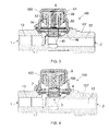
- FIG. 1 shows the outer appearance of an embodiment of the shut-off gas valve 100 of the invention by way of example.
- the valve 100 comprises a gas inlet 1 through which it receives gas from an external source, a gas outlet 2 through which the gas exits the valve 100, an intermediate orifice 3 through which the outlet 2 is communicated with the inlet 1 and gas reaches the outlet 2 from the inlet 1, a closure member 45 blocking or closing the intermediate orifice 3 in a closing position, preventing the passage of gas towards the outlet 2, and not cooperating with the intermediate orifice 3 in an opening position, not preventing said passage of gas, and an electromagnetic actuator acting on the closure member 45 to cause it to change position.
- FIG 2 shows an embodiment of an electromagnetic actuator of the valve 100 of the invention by way of example.
- the electromagnetic actuator comprises a static armature, a static permanent magnet 50 and a movable element which is attached to the closure member 45, the closure member 45 moving integrally with the movable element.
- the movable element comprises a bobbin 54 associated with the armature with freedom of movement in a direction Y and a coil 53 which is wound around and attached to the bobbin 54.
- the armature comprises a first member 51 comprising a circular section 51a and a cylindrical section 51b prolonging centrally and perpendicularly from the circular section 51a, and a second annular member 52.
- the cylindrical section 51b is housed at least partially in the bobbin 54, the bobbin 54 being associated with the armature by means of the first member 51.
- the second member 52 is traversed by the bobbin 54, by the coil 53 wound around and fixed to the bobbin 54 and by the cylindrical section 51b of the first member 51.
- the permanent magnet 50 remains secured and static between both members 51 and 52 of the armature, which further maintain their position with the aid of the permanent magnetic field generated by the permanent magnet 50.
- the permanent magnet 50 has an annular shape and, like the second member 52 of the armature, is traversed by the bobbin 54, by the coil 53 wound around and fixed to the bobbin 54 and by the cylindrical section 51b of the first member 51.
- the closure member 45 (not shown in Figure 2 ) is at least partially snap fitted in the bobbin 54, thereby being attached to said bobbin 54.
- the movement of the movable element, and therefore of the closure member 45 attached to it, occurs depending on the power supply of the coil 53.
- the coil 53 starts to be fed with a specific current, a magnetic field interacting with the permanent magnetic field generated by the permanent magnet 50 is generated, causing the movement of the movable element in the direction Y and therefore of the closure member 45 since both the armature and the permanent magnet 50 are static.
- the movable element When the coil 53 is no longer fed, the movable element can move in the opposite direction so that the closure member 45 returns to its initial position as a result of a spring 9 (not shown in Figure 2 ) which exerts a force on the closure member 45 and which will be described below, or said movement can occur when the coil 53 is fed with a current in the opposite direction, as will also be described below.
- the spring 9 can further be used to confer the initial state of the valve 10, open (closure member 45 in opening position) or closed (closure member 45 in the closing position).
- the valve 100 comprises a body 107 incorporating the inlet 1, the outlet 2, the intermediate orifice 3, an inlet conduit 13 communicating the inlet 1 with the intermediate orifice 3 and an outlet conduit 32 communicating the intermediate orifice 3 with the outlet 2.
- the intermediate orifice 3 and part of the inlet conduit 13 are accessible from outside the body 107, and the valve 100 comprises a casing 103 which is attached to the body 107 and closes the access from outside to said part of the inlet conduit 13 and to the intermediate orifice 3, and a sealing member 46 for closing the area of attachment between the body 107 and the casing 103 in a leak-tight manner.
- the body 107 delimits a first enclosure inside the valve 100 and a second enclosure is delimited inside the valve 100 between the body 107 and the casing 103 where the electromagnetic actuator is housed, the second enclosure being communicated at all times with the first enclosure.
- shut-off valve 100 corresponds to an ON - OFF type shut-off valve, such that the closure member 45 changes position when the coil 53 is fed and when the coil 53 is no longer fed.
- the closure member 45 and the sealing member 46 are part of one and the same element corresponding to a membrane 4 which is made from an elastomeric material and splits the inside of the valve 100 into the first enclosure and into the second enclosure, the first enclosure being delimited by the body 107 and a first face of the membrane 4 and the second enclosure being delimited by a second opposite face of the membrane 4 and the casing 103.
- an elastic membrane 4 is used, on one hand the same element assures the sealing against the exterior between the casing 103 and the body 107 (function of the sealing member 46) and on the other hand the same element allows blocking the intermediate orifice 3 (function of the closure member 45). Furthermore, as a result of using a membrane 4 the centering of the closure member 45 with respect to the intermediate orifice 3 can be improved in a simple manner.
- the membrane 4 is made of an elastomeric material, so the incorporation of a membrane 4 does not require a significant energy increase for moving the closure member 45 as a result of its elastic properties, the indicated advantages being obtained without any adverse effects worth mentioning.
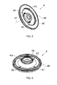
- the membrane 4 comprises a plurality of through holes 40 whereby the second enclosure of the valve 100 is communicated with the first enclosure of said valve 100, at least part of the gas from the inlet 1 reaching the second enclosure by means of the through holes 40.
- the membrane 4 comprises four through holes 40 and they are distributed symmetrically with respect to a central axis 49 of the membrane 4, such that the gas traversing the through holes 40 does not generate different side tensions in the membrane 4 that could negatively affect the centering of the closure member 45 with respect to the intermediate orifice 3.
- the gas is present in both enclosures inside the valve 100, and there is no difference in pressures caused by the gas between the two faces of the membrane 4, such that to move the closure member 45 from one position to another, the force exerted on said closure member 45 due to the difference in pressures between its two opposite faces has no effect whatsoever, so the energy needs of the electromagnetic actuator for moving the closure member 45 drop with respect to a solution without through holes 40, where the two enclosures would not be communicated, and lower energy consumption of the valve 100 is achieved.
- the membrane 4 allows facilitating its manufacture, particularly its assembly.
- the membrane 4 can thus be arranged in its position on the body 107, the electromagnetic actuator can then be assembled and finally the casing 103 can be attached to the body 107.
- the valve 100 further comprises a printed circuit board 7 which is attached to the electromagnetic actuator and through which the power supply reaches the coil 53, arranged in the second enclosure inside the valve 100 and comprising a section (not depicted in the drawings) accessible from outside the valve 100 through which the power supply arrives for the electromagnetic actuator (for the coil 53), so the electromagnetic actuator is fed in a simple manner from outside the valve 100.
- the valve 100 further comprises an additional element 8 arranged in the second enclosure on the printed circuit board 7 to prevent the inside of the valve 100 from having outward leaks due to the section of the printed circuit board 7 which is accessible from the outside.
- the printed circuit board 7 is therefore arranged between the membrane 4 and the additional element 8.
- the additional element 8 preferably corresponds to an O-ring or an equivalent element.
- the spring 9 causes the closure member 45 to be in a specific (closed or open) position at first, which state in the valve 100 is commonly referred to normally as open (closure member 45 in an opening position) or normally as closed (closure member 45 in a closing position).
- the resulting force that is generated due to its magnetic field and to that of the permanent magnet 50 causes the movement of the closure member 45 towards its closing position or towards its opening position (depending on how the valve 100 is initially configured), overcoming the force exerted by the spring 9 on the closure member 45.
- the resulting force disappears or drops and the closure member 45 recovers its previous position as a result of the force exerted by the spring 9.
- the spring 9 forces the valve 100 to be normally closed, it is arranged in the second enclosure of the valve 100, attached at a first end to the casing 103, associated at a second end with the closure member 45 and compressed or decompressed when the closure member 45 changes position.
- the first armature 105 comprises a central hole 105c for housing the spring 9, and inside the bobbin 54 the valve 100 comprises an element 106 fixed to the bobbin 54 to which the second end of the spring 9 is attached, said second end thereby being associated with the closure member 45.
- the spring 9 is housed at least partially in the bobbin 9.
- the valve 100 can be similar to the valve of the first embodiment but it can comprise a number of through holes 40 different from four (even just one), can have a different distribution of the through holes 40, and/or can comprise a different configuration so that the spring 9 forces the valve 100 to be normally open instead of normally closed, the coil 53 needing to be fed so that it closes instead of opens.
- the shut-off valve 100 corresponds to a flip-flop shut-off valve, such that the closure member 45 changes position when the coil 53 is fed and maintains its position in response to the absence of power supply of the coil 53, one power supply pulse being enough to cause the change of position and the direction of the movement of the movable element depending on the polarity of said pulse.
- the valve 100 of the second embodiment is similar to the valve of the first embodiment but further comprises two ferromagnetic elements 61 and 62 to turn it into a flip-flop valve.
- the ferromagnetic elements 61 and 62 are fixed to the movable element and are positioned such that when the coil 53 is fed, the ferromagnetic elements 61 and 62 are located within the magnetic field resulting from the cooperation between the magnetic fields of the permanent magnet 50 and of the coil 53 itself. Therefore due to its ferromagnetic properties, when the closure member 45 moves to the opening position due to the power supply of the coil 53 the ferromagnetic elements 61 and 62 are attracted by the permanent magnet 50, thereby staying that way even in response to the absence of power supply of the coil 53 (the magnetic field of the permanent magnet 50 alone is enough to keep it like that). The power supply of the electromagnetic actuator therefore does not need to be maintained to keep the valve 100 open, and lower consumption of the valve 100 is achieved, a flip-flop behavior being achieved in the valve 100.
- a small pulse P-ON of the current I of a specific amplitude I 0 in one direction is therefore enough to open the valve 100, in the order of milliamperes (mA), and a small pulse P-OFF of the current I of a specific amplitude I 0 in the opposite direction is enough to close the valve 100, as shown by way of example in Figure 9 .
- the first ferromagnetic element 61 is arranged inside the bobbin 54, fixed to said bobbin 54, and the second ferromagnetic element 62 is arranged outside said bobbin 54, fixed to said bobbin 54.
- the first ferromagnetic element 61 preferably corresponds to a disc and the second ferromagnetic element 62 corresponds to an annular part, and they are concentric with respect to a central axis 55 of the bobbin.
- the first ferromagnetic element 61 could perform the function of the element 106 described in the first embodiment, so in this case said element 106 would not be necessary (the second end of the spring 9 would be fixed to the first ferromagnetic element 61).
- valve 100 can be similar to the valve of the second embodiment but can comprise a number of through holes 40 different from four (even just one), can have a different distribution of the through holes 40, and/or can comprise a different configuration so that the spring 9 forces the valve 100 to be normally open instead of normally closed, the coil 53 needing to be fed so that it closes instead of opens.
- two ferromagnetic elements 61 and 62 other embodiments can comprise a single ferromagnetic element arranged inside the bobbin 54 or arranged outside the bobbin 54 (surrounding it).
- valve 100 would not need the element 106 because the ferromagnetic element would perform its function; the second end of the spring 9 would be fixed to the ferromagnetic element.
- the lines of the magnetic field generated by the permanent magnet 50 that are used are smaller than in the case of having two ferromagnetic elements, so the necessary power supply of the coil 53 would be greater.
- the ferromagnetic elements 61 and 62 can comprise an intentionally selected Curie temperature to provide thermal safety.
- the Curie temperature is reached in the area surrounding the ferromagnetic elements 61 and 62, said ferromagnetic elements 61 and 62 lose their ferromagnetic properties and are no longer attracted by the permanent magnet 50, the spring 9 causing the closure member 45 to return to its closing position even though the coil 53 has not been fed with a current pulse P-OFF.
- the Curie temperature can be comprised for example between 90°C and 130°C, corresponding to the temperature that can be reached in the area around the valve 100 when it (and/or the appliance in which it is assembled) is working in normal conditions. If this temperature is exceeded, it is interpreted that an anomaly has occurred (a fire, for example), and the passage of gas through the valve 100 is cut off to prevent possible greater damage.
- the choice of the Curie temperature could also be different, depending on the area in which the use of the valve 100 is envisaged.
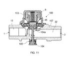
- the shut-off valve 100 corresponds to a flip-flop shut-off valve that can be operated manually.
- the valve 100 of the third embodiment is similar to the valve of the second embodiment but further comprises a manual actuator 104 accessible from the outside so that it can be operated manually.
- the position of the valve 100 can be changed manually from closed to open, but not from open to closed. The valve 100 could therefore be used even in response to the absence of electric energy, because it could be opened manually.
- valve 100 of the third embodiment acts electronically, so its operation will not be explained again. Its manual operation is explained below.
- the manual actuator 104 When the manual actuator 104 is operated manually, said actuator acts on the closure member 45 moving it to the opening position. Due to the permanent magnetic field of the permanent magnet 50, the ferromagnetic elements 61 and 62 are attracted by the permanent magnet 50, and they stay that way until the coil 53 is fed with a pulse P-OFF or until the ferromagnetic elements 61 and 61 lose their ferromagnetic properties (where appropriate).
- the manual actuator 104 comprises one end 104a pushing on the closure member 45 when it is actuated, said pushing causing the movement of the closure member 45 to the opening position.
- the valve 100 further comprises a spring 105 associated with the manual actuator 104 to cause the manual actuator 104 to recover its initial position once it is no longer being actuated (this allows for example the valve 100 being able to close with a pulse P-OFF of the coil 53 or, where appropriate, if the ferromagnetic elements 61 and 62 lose their ferromagnetic properties).
- the valve 100 can be similar to the valve of the third embodiment but can comprise a number of through holes 40 different from four (even just one), can have a different distribution of the through holes 40, and/or can comprise a different configuration so that the spring 9 forces the valve 100 to be normally open instead of normally closed, the coil 53 needing to be fed so that it closes instead of opens.
- the valve 100 instead of two ferromagnetic elements 61 and 62, other embodiments can comprise a single ferromagnetic element arranged inside the bobbin 54 or arranged outside the bobbin 54 (surrounding it).
- valve 100 would not need the part 106 because the ferromagnetic element would perform its function; the second end of the spring 9 would be fixed to the ferromagnetic element.
- the lines of the magnetic field generated by the permanent magnet 50 that are used are smaller than in the case of having two ferromagnetic elements, so the necessary power supply of the coil 53 would be greater.
Landscapes
- Engineering & Computer Science (AREA)
- General Engineering & Computer Science (AREA)
- Mechanical Engineering (AREA)
- Physics & Mathematics (AREA)
- Electromagnetism (AREA)
- Chemical & Material Sciences (AREA)
- Combustion & Propulsion (AREA)
- Fluid Mechanics (AREA)
- Magnetically Actuated Valves (AREA)
Priority Applications (9)
| Application Number | Priority Date | Filing Date | Title |
|---|---|---|---|
| EP13382194.2A EP2808607A1 (fr) | 2013-05-27 | 2013-05-27 | Soupape de gaz d'arrêt |
| EP14727797.4A EP3004740B1 (fr) | 2013-05-27 | 2014-05-26 | Soupape d'arrêt de gaz |
| CN201480028732.XA CN105339737B (zh) | 2013-05-27 | 2014-05-26 | 截止气阀 |
| PL14727797T PL3004740T3 (pl) | 2013-05-27 | 2014-05-26 | Zawór odcinający przepływ gazu |
| ES14727797.4T ES2643178T3 (es) | 2013-05-27 | 2014-05-26 | Válvula de cierre de gas |
| PCT/EP2014/060820 WO2014191349A1 (fr) | 2013-05-27 | 2014-05-26 | Vanne d'arret de gaz |
| RU2015152817A RU2015152817A (ru) | 2013-05-27 | 2014-05-26 | Запорный газовый клапан |
| CA2913327A CA2913327C (fr) | 2013-05-27 | 2014-05-26 | Vanne d'arret de gaz |
| US14/948,783 US10054244B2 (en) | 2013-05-27 | 2015-11-23 | Shut-off gas valve |
Applications Claiming Priority (1)
| Application Number | Priority Date | Filing Date | Title |
|---|---|---|---|
| EP13382194.2A EP2808607A1 (fr) | 2013-05-27 | 2013-05-27 | Soupape de gaz d'arrêt |
Publications (1)
| Publication Number | Publication Date |
|---|---|
| EP2808607A1 true EP2808607A1 (fr) | 2014-12-03 |
Family
ID=48577665
Family Applications (2)
| Application Number | Title | Priority Date | Filing Date |
|---|---|---|---|
| EP13382194.2A Withdrawn EP2808607A1 (fr) | 2013-05-27 | 2013-05-27 | Soupape de gaz d'arrêt |
| EP14727797.4A Active EP3004740B1 (fr) | 2013-05-27 | 2014-05-26 | Soupape d'arrêt de gaz |
Family Applications After (1)
| Application Number | Title | Priority Date | Filing Date |
|---|---|---|---|
| EP14727797.4A Active EP3004740B1 (fr) | 2013-05-27 | 2014-05-26 | Soupape d'arrêt de gaz |
Country Status (8)
| Country | Link |
|---|---|
| US (1) | US10054244B2 (fr) |
| EP (2) | EP2808607A1 (fr) |
| CN (1) | CN105339737B (fr) |
| CA (1) | CA2913327C (fr) |
| ES (1) | ES2643178T3 (fr) |
| PL (1) | PL3004740T3 (fr) |
| RU (1) | RU2015152817A (fr) |
| WO (1) | WO2014191349A1 (fr) |
Families Citing this family (8)
| Publication number | Priority date | Publication date | Assignee | Title |
|---|---|---|---|---|
| PL3205935T3 (pl) * | 2016-02-11 | 2019-11-29 | Copreci S Coop | Urządzenie gazowe zawierające kurek gazowy i urządzenie sterujące |
| CA3030620C (fr) | 2016-07-11 | 2022-09-20 | Copreci, S.Coop. | Appareil de cuisson a gaz |
| TWI628396B (zh) * | 2017-02-24 | 2018-07-01 | 金博士工業有限公司 | Gas measurement and leak detection device |
| CN206617634U (zh) * | 2017-03-27 | 2017-11-07 | 上海荣威塑胶工业有限公司 | 节水阀及喷水玩具 |
| EP3541090A1 (fr) * | 2018-03-16 | 2019-09-18 | Ole Wolff Elektronik A/S | Valve micro acoustique réglable |
| US11118702B2 (en) * | 2018-07-23 | 2021-09-14 | Buerkert Werke Gmbh & Co. Kg | Valve with energy-saving electrodynamic actuator |
| US11054051B2 (en) | 2019-04-09 | 2021-07-06 | Copreci, S.Coop. | Gas shut-off valve for a gas cooking appliance and gas cooking appliance incorporating said gas shut-off valve |
| CN110397748A (zh) * | 2019-08-09 | 2019-11-01 | 东风富士汤姆森调温器有限公司 | 炭罐通风磁力阀 |
Citations (5)
| Publication number | Priority date | Publication date | Assignee | Title |
|---|---|---|---|---|
| US2502591A (en) * | 1943-09-13 | 1950-04-04 | Gen Controls Co | Electromagnet |
| US20030020037A1 (en) | 2001-07-12 | 2003-01-30 | Pierog Dennis W. | Control valve with integral solenoid and regulator for gas appliances |
| EP1382907A1 (fr) * | 2002-07-12 | 2004-01-21 | G. Kromschröder Aktiengesellschaft | Dispositif pour régler le débit de gaz dans un brûleur |
| EP2423545A1 (fr) * | 2010-08-27 | 2012-02-29 | Coprececitec, S.L. | Vanne de gaz |
| EP2444730A1 (fr) * | 2010-10-19 | 2012-04-25 | Coprecitec, S.L. | Méthode de montage d'un robinet de gaz électromagnétiques, et vanne de gaz électromagnétique |
Family Cites Families (20)
| Publication number | Priority date | Publication date | Assignee | Title |
|---|---|---|---|---|
| US2466515A (en) * | 1949-04-05 | Thermomagnetic safety pilot | ||
| US2309709A (en) * | 1941-08-15 | 1943-02-02 | Gen Controls Co | Manual reset valve |
| US2520591A (en) * | 1946-04-09 | 1950-08-29 | Harry T Wilmarth | Control cock for gaseous fuel burners burning a mixture of two gases |
| US2826215A (en) * | 1954-04-21 | 1958-03-11 | Alco Valve Co | Balanced pressure solenoid valve |
| US2915681A (en) * | 1957-11-20 | 1959-12-01 | Indiana Steel Products Co | Magnet assemblies |
| US3420492A (en) * | 1965-10-06 | 1969-01-07 | Itt | Bistable valve mechanism or the like |
| US4403765A (en) * | 1979-11-23 | 1983-09-13 | John F. Taplin | Magnetic flux-shifting fluid valve |
| US4632358A (en) * | 1984-07-17 | 1986-12-30 | Eaton Corporation | Automotive air conditioning system including electrically operated expansion valve |
| DE3527174A1 (de) * | 1985-07-30 | 1987-02-12 | Bosch Gmbh Robert | Doppeltwirkendes magnetventil |
| US4683452A (en) * | 1986-06-30 | 1987-07-28 | Regdon Solenoid, Inc. | Bi-stable electromagnetic actuator |
| US5272458A (en) * | 1988-07-28 | 1993-12-21 | H-U Development Corporation | Solenoid actuator |
| JPH03157576A (ja) * | 1989-11-15 | 1991-07-05 | Aisin Aw Co Ltd | 三方電磁弁及びその製造方法 |
| US5094218A (en) * | 1991-03-22 | 1992-03-10 | Siemens Automotive Limited | Engine exhaust gas recirculation (EGR) |
| JP3322772B2 (ja) * | 1995-05-22 | 2002-09-09 | 日本エム・ケー・エス株式会社 | 制御弁 |
| JP3591429B2 (ja) * | 2000-06-22 | 2004-11-17 | オムロンヘルスケア株式会社 | 流量コントロール弁及び血圧計 |
| US6715475B2 (en) * | 2001-10-26 | 2004-04-06 | Siemens Vdo Automotive, Incorporated | Exhaust gas recirculation valve |
| DE202007002760U1 (de) * | 2007-02-26 | 2007-04-26 | Barabas-Lammert, Kurt, Dr. | Stellantrieb für Regelventile und/oder Absperrarmaturen |
| DE102008027546A1 (de) * | 2008-06-10 | 2009-12-17 | Heatec Thermotechnik Gmbh | Kombinierte Ventileinrichtung |
| DE102009015231A1 (de) * | 2009-04-01 | 2010-10-07 | Focke & Co.(Gmbh & Co. Kg) | (Leim-)Ventil |
| US8746280B2 (en) * | 2009-04-06 | 2014-06-10 | Airbus Operations Gmbh | Controllable valve for an aircraft |
-
2013
- 2013-05-27 EP EP13382194.2A patent/EP2808607A1/fr not_active Withdrawn
-
2014
- 2014-05-26 ES ES14727797.4T patent/ES2643178T3/es active Active
- 2014-05-26 RU RU2015152817A patent/RU2015152817A/ru not_active Application Discontinuation
- 2014-05-26 PL PL14727797T patent/PL3004740T3/pl unknown
- 2014-05-26 WO PCT/EP2014/060820 patent/WO2014191349A1/fr active Application Filing
- 2014-05-26 CA CA2913327A patent/CA2913327C/fr active Active
- 2014-05-26 EP EP14727797.4A patent/EP3004740B1/fr active Active
- 2014-05-26 CN CN201480028732.XA patent/CN105339737B/zh active Active
-
2015
- 2015-11-23 US US14/948,783 patent/US10054244B2/en active Active
Patent Citations (5)
| Publication number | Priority date | Publication date | Assignee | Title |
|---|---|---|---|---|
| US2502591A (en) * | 1943-09-13 | 1950-04-04 | Gen Controls Co | Electromagnet |
| US20030020037A1 (en) | 2001-07-12 | 2003-01-30 | Pierog Dennis W. | Control valve with integral solenoid and regulator for gas appliances |
| EP1382907A1 (fr) * | 2002-07-12 | 2004-01-21 | G. Kromschröder Aktiengesellschaft | Dispositif pour régler le débit de gaz dans un brûleur |
| EP2423545A1 (fr) * | 2010-08-27 | 2012-02-29 | Coprececitec, S.L. | Vanne de gaz |
| EP2444730A1 (fr) * | 2010-10-19 | 2012-04-25 | Coprecitec, S.L. | Méthode de montage d'un robinet de gaz électromagnétiques, et vanne de gaz électromagnétique |
Also Published As
| Publication number | Publication date |
|---|---|
| CN105339737B (zh) | 2017-11-21 |
| US10054244B2 (en) | 2018-08-21 |
| ES2643178T3 (es) | 2017-11-21 |
| CN105339737A (zh) | 2016-02-17 |
| WO2014191349A1 (fr) | 2014-12-04 |
| EP3004740B1 (fr) | 2017-09-27 |
| RU2015152817A (ru) | 2017-06-28 |
| CA2913327A1 (fr) | 2014-12-04 |
| CA2913327C (fr) | 2021-07-13 |
| US20160265677A1 (en) | 2016-09-15 |
| PL3004740T3 (pl) | 2018-03-30 |
| EP3004740A1 (fr) | 2016-04-13 |
Similar Documents
| Publication | Publication Date | Title |
|---|---|---|
| US10054244B2 (en) | Shut-off gas valve | |
| US4988074A (en) | Proportional variable force solenoid control valve | |
| EP2567131B1 (fr) | Dispositifs de commutation à actionnement électromagnétique et procédés pour leur actionnement | |
| US8567062B2 (en) | Method for assembling an electromagnetic gas valve, and electromagnetic gas valve | |
| CA2693851A1 (fr) | Vanne pilote resistant aux obturations | |
| EP3009742B1 (fr) | Appareil à gaz comprenant une soupape | |
| US6943657B2 (en) | Solenoid and valve assembly having a linear output | |
| WO2014174759A1 (fr) | Commande de soupape à fonctionnalité de protection contre le débordement | |
| US9704636B2 (en) | Solenoid apparatus | |
| WO2012118698A2 (fr) | Solénoïde à force variable à deux étages | |
| EP2954244A1 (fr) | Vanne magnétique comprenant une armature disposée à l'intérieur d'un piston | |
| JPS6159428B2 (fr) | ||
| US10041598B2 (en) | Coaxially designed, pressure-compensated, directly controlled valve with low pressure losses | |
| CN109519549B (zh) | 电磁气体阀、气体调节阀以及燃气烹饪用具 | |
| RU2343328C2 (ru) | Электромагнитный клапан (варианты) | |
| EP3597937B1 (fr) | Servovanne | |
| EP2594834B1 (fr) | Électrovanne normalement ouverte avec actionnement indirect et mixte | |
| KR100945166B1 (ko) | 전자식 가스 차단기 | |
| GB2379726A (en) | Electro-magnetically operated device | |
| US20180355993A1 (en) | Hydraulic valve configuration for nh vbs with a nl solenoid | |
| EP3205935B1 (fr) | Appareil à gaz comprenant un robinet à gaz et un dispositif de commande |
Legal Events
| Date | Code | Title | Description |
|---|---|---|---|
| PUAI | Public reference made under article 153(3) epc to a published international application that has entered the european phase |
Free format text: ORIGINAL CODE: 0009012 |
|
| 17P | Request for examination filed |
Effective date: 20130527 |
|
| AK | Designated contracting states |
Kind code of ref document: A1 Designated state(s): AL AT BE BG CH CY CZ DE DK EE ES FI FR GB GR HR HU IE IS IT LI LT LU LV MC MK MT NL NO PL PT RO RS SE SI SK SM TR |
|
| AX | Request for extension of the european patent |
Extension state: BA ME |
|
| STAA | Information on the status of an ep patent application or granted ep patent |
Free format text: STATUS: THE APPLICATION IS DEEMED TO BE WITHDRAWN |
|
| 18D | Application deemed to be withdrawn |
Effective date: 20150604 |