EP2808594B1 - Panning slider - Google Patents
Panning slider Download PDFInfo
- Publication number
- EP2808594B1 EP2808594B1 EP14164602.6A EP14164602A EP2808594B1 EP 2808594 B1 EP2808594 B1 EP 2808594B1 EP 14164602 A EP14164602 A EP 14164602A EP 2808594 B1 EP2808594 B1 EP 2808594B1
- Authority
- EP
- European Patent Office
- Prior art keywords
- rails
- carriage
- guide member
- affixed
- respect
- Prior art date
- Legal status (The legal status is an assumption and is not a legal conclusion. Google has not performed a legal analysis and makes no representation as to the accuracy of the status listed.)
- Not-in-force
Links
- 238000004091 panning Methods 0.000 title claims description 19
- 230000003466 anti-cipated effect Effects 0.000 description 1
- 230000000694 effects Effects 0.000 description 1
- 230000005484 gravity Effects 0.000 description 1
- 230000004048 modification Effects 0.000 description 1
- 238000012986 modification Methods 0.000 description 1
Images


Classifications
-
- G—PHYSICS
- G03—PHOTOGRAPHY; CINEMATOGRAPHY; ANALOGOUS TECHNIQUES USING WAVES OTHER THAN OPTICAL WAVES; ELECTROGRAPHY; HOLOGRAPHY
- G03B—APPARATUS OR ARRANGEMENTS FOR TAKING PHOTOGRAPHS OR FOR PROJECTING OR VIEWING THEM; APPARATUS OR ARRANGEMENTS EMPLOYING ANALOGOUS TECHNIQUES USING WAVES OTHER THAN OPTICAL WAVES; ACCESSORIES THEREFOR
- G03B17/00—Details of cameras or camera bodies; Accessories therefor
- G03B17/56—Accessories
- G03B17/561—Support related camera accessories
-
- F—MECHANICAL ENGINEERING; LIGHTING; HEATING; WEAPONS; BLASTING
- F16—ENGINEERING ELEMENTS AND UNITS; GENERAL MEASURES FOR PRODUCING AND MAINTAINING EFFECTIVE FUNCTIONING OF MACHINES OR INSTALLATIONS; THERMAL INSULATION IN GENERAL
- F16M—FRAMES, CASINGS OR BEDS OF ENGINES, MACHINES OR APPARATUS, NOT SPECIFIC TO ENGINES, MACHINES OR APPARATUS PROVIDED FOR ELSEWHERE; STANDS; SUPPORTS
- F16M11/00—Stands or trestles as supports for apparatus or articles placed thereon ; Stands for scientific apparatus such as gravitational force meters
- F16M11/02—Heads
- F16M11/18—Heads with mechanism for moving the apparatus relatively to the stand
-
- F—MECHANICAL ENGINEERING; LIGHTING; HEATING; WEAPONS; BLASTING
- F16—ENGINEERING ELEMENTS AND UNITS; GENERAL MEASURES FOR PRODUCING AND MAINTAINING EFFECTIVE FUNCTIONING OF MACHINES OR INSTALLATIONS; THERMAL INSULATION IN GENERAL
- F16M—FRAMES, CASINGS OR BEDS OF ENGINES, MACHINES OR APPARATUS, NOT SPECIFIC TO ENGINES, MACHINES OR APPARATUS PROVIDED FOR ELSEWHERE; STANDS; SUPPORTS
- F16M11/00—Stands or trestles as supports for apparatus or articles placed thereon ; Stands for scientific apparatus such as gravitational force meters
- F16M11/02—Heads
- F16M11/04—Means for attachment of apparatus; Means allowing adjustment of the apparatus relatively to the stand
- F16M11/06—Means for attachment of apparatus; Means allowing adjustment of the apparatus relatively to the stand allowing pivoting
- F16M11/08—Means for attachment of apparatus; Means allowing adjustment of the apparatus relatively to the stand allowing pivoting around a vertical axis, e.g. panoramic heads
-
- F—MECHANICAL ENGINEERING; LIGHTING; HEATING; WEAPONS; BLASTING
- F16—ENGINEERING ELEMENTS AND UNITS; GENERAL MEASURES FOR PRODUCING AND MAINTAINING EFFECTIVE FUNCTIONING OF MACHINES OR INSTALLATIONS; THERMAL INSULATION IN GENERAL
- F16M—FRAMES, CASINGS OR BEDS OF ENGINES, MACHINES OR APPARATUS, NOT SPECIFIC TO ENGINES, MACHINES OR APPARATUS PROVIDED FOR ELSEWHERE; STANDS; SUPPORTS
- F16M11/00—Stands or trestles as supports for apparatus or articles placed thereon ; Stands for scientific apparatus such as gravitational force meters
- F16M11/42—Stands or trestles as supports for apparatus or articles placed thereon ; Stands for scientific apparatus such as gravitational force meters with arrangement for propelling the support stands on wheels
- F16M11/425—Stands or trestles as supports for apparatus or articles placed thereon ; Stands for scientific apparatus such as gravitational force meters with arrangement for propelling the support stands on wheels along guiding means
Definitions
- This present disclosure relates to a motion control device, such as a slider, suitable for moving an object, such as a camera, along a defined path.
- Sliders are well known in the photographic and cinematographic arts.
- a slider is typically defined by a rail system having a pair of parallel rails with a slider tray carried on the rails and a camera is mounted to the slider tray. Sliders are useful for producing a camera shot where the camera needs to be moved along a defined path. Sliders may define a straight or curved path, and allow for a smooth and repeatable camera movement.
- One common camera movement which illustrates the difficulty of coordinating the pan and slide movements is a "fixed point shot.”
- the desired effect is to have the camera remain focused on a given stationary point spaced some distance from the slider as the camera moves along the rails.
- the camera In order for the camera to point at the given point during the travel along the rails, the camera must rotate at a rate such that at any given position along the rails, the camera is pointed directly at the given point.
- previous slider systems are capable of producing such a shot, they are only able to do so if set up by a highly skilled technician who carefully calibrates each of the respective motors. Therefore, an improved panning slider is needed.
- the present disclosure describes a rail system having a pair of parallel rails for moving and panning a camera or other photographic equipment during a photo shoot, such as disclosed for example in US 2009315288
- a carriage rides on the rails along a path defined by the rails.
- the rail system includes a guide member which is positionable independent to the pair of parallel rails.
- the carriage includes a table which is rotatably mounted on the carriage; the table is also mounted to an arm which rides on a carriage, which carriage is carried by the guide rail. In this way, the arm causes the table to rotate as the distance between the guide rail and the parallel rails changes, which rotation causes the camera to pan.
- One embodiment of the pan system pivots the guide rail at or near the center of the guide rail. This prevents the mean position of the guide being overly close or far away from the carriage. If the guide rail is too close or too far away, the assembly might bind at certain points in the linear travel.
- Another embodiment involves the guide rail that is skewed to the parallel rails in two axes.
- the table is attached to the carriage such that it has more than one degree of freedom. This would allow the camera to pan side to side and up and down. This could be particularly useful if the camera needs to follow an object that moves in relation to the camera. At times, it may be desirable for the guide rail to be non-linear. This way a variable point can be followed as the carriage travels along the parallel rails.
- the degree of the pan is dictated by the angle of the guide rail.
- the present disclosure describes a rail system which pans a camera as it moves along a rail system without the use of a pan motor.
- the present disclosure describes a rail system 10 having a pair of parallel rails 12, 14 as shown in FIG. 11 .
- the movable assembly 8, as shown in FIGS 8 & 9 include a carriage 16, an arm 40, and a linear bearing 46.
- the carriage 16 rides on the parallel rails 12, 14 and is movable along a path defined by the parallel rails 12, 14.
- the parallel rails 12, 14 are fixed relative one another by a frame 17 as shown in FIG. 5 .
- the frame 17 is adapted for holding the rails 12, 14 and providing structure to the rail system 10.
- the frame 17, as depicted here is constructed from a pair of upright walls 13, 15 which mount the rails 12,14, as is shown in FIG.
- the spanning members 19 collectively define the base on which the rail system 10 is supported.
- the spanning members 19 may include one or more apertures suitable for accepting a fastener for mounting the rail system 10 to a surface.
- the spanning members 19 include apertures which allow the rail system 10 to be mounted to any suitable surface, be it a horizontal surface like the ground, a vertical surface like a wall, or any other suitable surface.
- Typical panning systems use motor-driven rotation for the camera, and such motors typically aren't engineered to be used in any orientation other than horizontal (the motors are typically not rated to pull against gravity when panning).
- the current system does not rely on a panning motor. Instead, the current system pans as the slider moves, thereby, the system which moves the slider also causes the panning action through the mechanical system. In this way, the present rail system 10 provides significant improvements and versatility as compared to previous slider systems.
- the rail system 10 includes a series of supports extending perpendicularly away from the parallel rails, preferably three supports 18, 20, 22 as is shown in FIGS. 2-5 .
- the three supports 18, 20, 22 together support a guide rail 24.
- the two outer supports 18, 22 are rods which each carry a respective slideable clamp 26, 28, with the respective clamp mounted to a crown 34 shaped to support the guide rail 24.
- the slidable clamps 26, 28 are movable along the respective outer supports 18, 22 to adjust the angle of the guide rail 24 relative the parallel rails 12, 14.
- the guide rail 24 is shown substantially parallel to the parallel rails 12, 14 in FIG. 2 and askew in FIGS. 3-5 .
- the middle support 20 includes a crown 34 which is shaped to support the guide rail 24.
- the crown 34 is mounted on a pivot member 36 about which the guide rail is rotatable on the middle support 20 to allow the guide rail 24 to pivot relative the parallel rails 12, 14. Different positions of the guide rail 24 are shown in FIGS. 2 and 3 .
- a table 38 is mounted to the upper surface of the carriage 16 such that the table 38 is rotatable relative the carriage 16 as is shown in FIG. 1 .
- the table 38 is pivotal on a shaft 39, which shaft 39 allows the table to rotate relative the carriage 16.
- the shaft 39 has a central axis about which the shaft 39 rotates.
- a bearing 41 FIG. 10 is sandwiched between the table 38 and the carriage 16 and surrounds the perimeter of the shaft 39, which bearing both provides support to the table 38, and allows smooth rotation thereof.
- an arm 40 is mounted at a pivot point 42 to table 38 near a perimeter edge of the table 38 in a way that allows the arm 40 to rotate the table 38.
- the arm 40 is mounted at a second end 44 to a linear bearing 46 which is slidable along the guide rail 24.
- the carriage 16 can either be driven manually by a handle 52 or with a motor.
- the handle 52 connects to a drive pulley 60 which is mated to a drive belt 62 as is shown in FIG. 10 .
- the carriage 16 is affixed to a section of the drive belt 62 via link 30, FIG. 9 .
- the drive pulley is a slave pulley 58 which is connected to a brake 56.
- the brake 56 provides a frictional drag to the slave pulley 58, which translates to drag on belt to resist motion.
- the amount of drag the brake 56 provides is adjusted by a knob 54 that is adjacent to the brake 56.
- the arm 40 will cause the table 38 to rotate relative the carriage 16.
- the linear bearing 46 moves toward or away from the carriage 16
- the arm 40 is moved by the linear bearing 46, which causes the table 38 to rotate due to the spacing between the pivot point of where the arm connects to the table and axis of the shaft 39. This spacing is best seen as distance "d" in FIG. 8 .
- This rotation of the table 38 is shown in FIGS. 3 and 4 .
- One application of the present invention is to mount a camera (not shown) to the table 38, such that as the camera travels along the parallel rails 12, 14, the guide rail 24 can be positioned at a preferred angle which will cause the camera to pan at a preferred rate as the carriage 16 moves along the rails 12, 14.
- the outer supports 18, 22 are rods which are joined at one end to the frame 17.
- Respective slidable clamps 26, 28, FIG. 7 are mounted to the outer supports 18, 22.
- the slidable clamps 26, 28 are adapted for being moved longitudinally along the length of the respective outer supports 18, 22, and are each clampable at a desired position along the outer supports 18, 22, with the position defining the angle at which the guide rail 24 is positioned relative the parallel rails 12, 14.
- the middle support 20, as mentioned, includes a pivot member 36.
- the pivot member 36 is mounted a fixed distance from the parallel rails 12, 14 as is shown in FIG. 5 .
- the linear bearing 46 is always a fixed distance from parallel rails 12, 14 when the carriage is located above the pivot member 36.
- the table 38 will be at a defined rotational position, preferably aligned such that an attached camera is aimed perpendicularly to the parallel rails 12, 14.
- the table will have rotated to a position where the camera is pointed perpendicularly to the parallel rails 12, 14.
- the fixed point shot is set up by first moving the slidable clamps 26, 28 to a position where the guide rail 24 is parallel with the parallel rails 12, 14, and centering the linear bearing 46 above the pivot member 36, as illustrated in FIG. 2 . In this position, the table 38 is aligned such that the camera will point perpendicularly to the parallel rails 12, 14, marked as B. The user then sets up the camera to be focused on the desired fixed point, marked as P. With the camera properly configured, the slidable clamps 26, 28 are moved to a desired position which positions the guide rail 24 at a specified angle relative the parallel rails 12, 14, such as is shown in FIG. 3 .
- the carriage 16 is subsequently moved to one end of the rail system 10, marked as A.
- the user then begins taking the shot and begins moving the carriage 16 along the parallel rails until the slider is positioned as is shown in FIG. 4 , marked as C.
- the linear bearing 46 moves along the guide rail 24 causing the arm 40 to rotate the table 38. This keeps the camera pointed at the fixed point throughout the movement of the carriage 16.
- the rail system 10 illustrated in the Figures is shown as a linear rail. It is anticipated that the present three-rail system could be used with either linear or curved rails to achieve the mechanical panning described herein.
- the carriage 16 is moved relative the frame 17 by any means known in the art, such as by a motor, by a hand crank, by hand, or by any other suitable system. It is also possible to have only the outer supports 18 and 22 as supports for the guide rail 24.
- the outer supports 18, 22 are joined to the frame 17 by respective mounts 48, 50, FIG. 5 .
- the mounts 48, 50 are each attached to the underside of the frame 17.
- the crown 34 is pivotally mounted to the respective slidable clamp 26, 28 to allow the guide rail 24 to move to the prescribed angle relative the parallel rails 12, 14.
Landscapes
- Engineering & Computer Science (AREA)
- General Engineering & Computer Science (AREA)
- Mechanical Engineering (AREA)
- Physics & Mathematics (AREA)
- General Physics & Mathematics (AREA)
- Accessories Of Cameras (AREA)
- Studio Devices (AREA)
Description
- This present disclosure relates to a motion control device, such as a slider, suitable for moving an object, such as a camera, along a defined path. Sliders are well known in the photographic and cinematographic arts. A slider is typically defined by a rail system having a pair of parallel rails with a slider tray carried on the rails and a camera is mounted to the slider tray. Sliders are useful for producing a camera shot where the camera needs to be moved along a defined path. Sliders may define a straight or curved path, and allow for a smooth and repeatable camera movement. It is common for motors to drive the slider so that the slider moves at a defined rate along the rails. Such motors are capable of providing precise movements at variable speeds.
- In some instances, it is desired to have the camera not only move along a defined path, but to also have the camera pan as it moves. Previously, panning required use of a motor which rotated the camera at a precise rate and a precise time relative to the motion of the slider as it moves on the rails. Such motors are expensive and require a high degree of skill, and considerable time to program for a given shot to ensure the camera pans and slides in unison.
- One common camera movement which illustrates the difficulty of coordinating the pan and slide movements is a "fixed point shot." In such a shot, the desired effect is to have the camera remain focused on a given stationary point spaced some distance from the slider as the camera moves along the rails. In order for the camera to point at the given point during the travel along the rails, the camera must rotate at a rate such that at any given position along the rails, the camera is pointed directly at the given point. While previous slider systems are capable of producing such a shot, they are only able to do so if set up by a highly skilled technician who carefully calibrates each of the respective motors. Therefore, an improved panning slider is needed.
- The present disclosure describes a rail system having a pair of parallel rails for moving and panning a camera or other photographic equipment during a photo shoot, such as disclosed for example in
US 2009315288 A carriage rides on the rails along a path defined by the rails. The rail system includes a guide member which is positionable independent to the pair of parallel rails. The carriage includes a table which is rotatably mounted on the carriage; the table is also mounted to an arm which rides on a carriage, which carriage is carried by the guide rail. In this way, the arm causes the table to rotate as the distance between the guide rail and the parallel rails changes, which rotation causes the camera to pan. One embodiment of the pan system pivots the guide rail at or near the center of the guide rail. This prevents the mean position of the guide being overly close or far away from the carriage. If the guide rail is too close or too far away, the assembly might bind at certain points in the linear travel. - Another embodiment involves the guide rail that is skewed to the parallel rails in two axes. The table is attached to the carriage such that it has more than one degree of freedom. This would allow the camera to pan side to side and up and down. This could be particularly useful if the camera needs to follow an object that moves in relation to the camera. At times, it may be desirable for the guide rail to be non-linear. This way a variable point can be followed as the carriage travels along the parallel rails.
- The degree of the pan is dictated by the angle of the guide rail. In this way, the present disclosure describes a rail system which pans a camera as it moves along a rail system without the use of a pan motor.
- A preferred embodiment of this invention has been chosen wherein:
-
FIG. 1 is a perspective view of the rail system of the present disclosure; -
FIG. 2 is a top view of the rail system ofFIG. 1 with the slider in the B position; -
FIG. 3 is a top view of the rail system ofFIG. 1 with the slider in the A position; -
FIG. 4 is a top view of the rail system ofFIG. 1 with the slider in the C position; -
FIG. 5 is a bottom view of the rail system ofFIG. 1 ; -
FIG. 6 is a side view of the rail system ofFIG. 1 ; -
FIG. 7 is an end view of the rail system ofFIG. 1 ; -
FIG. 8 is a perspective view of the movable assembly ofFIG. 1 ; -
FIG. 9 is an underneath perspective view of the movable assembly ofFIG. 1 ; -
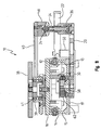
FIG. 10 is a partial side section 10 - 10 view of the rail system ofFIG. 1 ; and -
FIG. 11 is an end section 11 - 11 view of the rail system ofFIG. 2 . - The present disclosure describes a
rail system 10 having a pair ofparallel rails FIG. 11 . Themovable assembly 8, as shown inFIGS 8 &9 include acarriage 16, anarm 40, and a linear bearing 46. Thecarriage 16 rides on theparallel rails parallel rails parallel rails frame 17 as shown inFIG. 5 . Theframe 17 is adapted for holding therails rail system 10. Theframe 17, as depicted here, is constructed from a pair ofupright walls rails FIG. 7 , which walls are connected by a series of spanningmembers 19, the spanning members defining a plurality ofopenings 21 which provide weight savings to therail system 10 as is shown inFIG. 5 . The spanningmembers 19 collectively define the base on which therail system 10 is supported. The spanningmembers 19 may include one or more apertures suitable for accepting a fastener for mounting therail system 10 to a surface. - One advantage of the
present rail system 10 is that it is suitable for use in any orientation. The spanningmembers 19 include apertures which allow therail system 10 to be mounted to any suitable surface, be it a horizontal surface like the ground, a vertical surface like a wall, or any other suitable surface. Typical panning systems use motor-driven rotation for the camera, and such motors typically aren't engineered to be used in any orientation other than horizontal (the motors are typically not rated to pull against gravity when panning). The current system does not rely on a panning motor. Instead, the current system pans as the slider moves, thereby, the system which moves the slider also causes the panning action through the mechanical system. In this way, thepresent rail system 10 provides significant improvements and versatility as compared to previous slider systems. - The
rail system 10 includes a series of supports extending perpendicularly away from the parallel rails, preferably three supports 18, 20, 22 as is shown inFIGS. 2-5 . The three supports 18, 20, 22 together support aguide rail 24. The twoouter supports slideable clamp crown 34 shaped to support theguide rail 24. Theslidable clamps outer supports guide rail 24 relative theparallel rails guide rail 24 is shown substantially parallel to theparallel rails FIG. 2 and askew inFIGS. 3-5 . Themiddle support 20 includes acrown 34 which is shaped to support theguide rail 24. Thecrown 34 is mounted on apivot member 36 about which the guide rail is rotatable on themiddle support 20 to allow theguide rail 24 to pivot relative theparallel rails guide rail 24 are shown inFIGS. 2 and3 . - A table 38 is mounted to the upper surface of the
carriage 16 such that the table 38 is rotatable relative thecarriage 16 as is shown inFIG. 1 . As illustrated inFIGS. 3 and4 , the table 38 is pivotal on ashaft 39, whichshaft 39 allows the table to rotate relative thecarriage 16. Theshaft 39 has a central axis about which theshaft 39 rotates. A bearing 41FIG. 10 , is sandwiched between the table 38 and thecarriage 16 and surrounds the perimeter of theshaft 39, which bearing both provides support to the table 38, and allows smooth rotation thereof. - As is shown in
FIG 7 , anarm 40 is mounted at apivot point 42 to table 38 near a perimeter edge of the table 38 in a way that allows thearm 40 to rotate the table 38. Thearm 40 is mounted at asecond end 44 to alinear bearing 46 which is slidable along theguide rail 24. - As assembled, when the
carriage 16 is moved laterally along theparallel rails guide rail 24. Thecarriage 16 can either be driven manually by ahandle 52 or with a motor. Thehandle 52 connects to a drivepulley 60 which is mated to adrive belt 62 as is shown inFIG. 10 . Thecarriage 16 is affixed to a section of thedrive belt 62 vialink 30,FIG. 9 . As thedrive belt 62 moves laterally, thecarriage 16 is pulled along. Opposite the drive pulley is aslave pulley 58 which is connected to abrake 56. Thebrake 56 provides a frictional drag to theslave pulley 58, which translates to drag on belt to resist motion. The amount of drag thebrake 56 provides is adjusted by aknob 54 that is adjacent to thebrake 56. As the distance between theparallel rails guide rail 24 changes, thearm 40 will cause the table 38 to rotate relative thecarriage 16. As thelinear bearing 46 moves toward or away from thecarriage 16, thearm 40 is moved by thelinear bearing 46, which causes the table 38 to rotate due to the spacing between the pivot point of where the arm connects to the table and axis of theshaft 39. This spacing is best seen as distance "d" inFIG. 8 . This rotation of the table 38 is shown inFIGS. 3 and4 . - One application of the present invention is to mount a camera (not shown) to the table 38, such that as the camera travels along the
parallel rails guide rail 24 can be positioned at a preferred angle which will cause the camera to pan at a preferred rate as thecarriage 16 moves along therails - As previously described, the outer supports 18, 22 are rods which are joined at one end to the
frame 17. Respective slidable clamps 26, 28,FIG. 7 are mounted to the outer supports 18, 22. The slidable clamps 26, 28 are adapted for being moved longitudinally along the length of the respective outer supports 18, 22, and are each clampable at a desired position along the outer supports 18, 22, with the position defining the angle at which theguide rail 24 is positioned relative theparallel rails - The
middle support 20, as mentioned, includes apivot member 36. In the preferred embodiment, thepivot member 36 is mounted a fixed distance from theparallel rails FIG. 5 . In this way, thelinear bearing 46 is always a fixed distance fromparallel rails pivot member 36. In this way, when thelinear bearing 46 is at thepivot member 36, the table 38 will be at a defined rotational position, preferably aligned such that an attached camera is aimed perpendicularly to theparallel rails linear bearing 46 arrives at thepivot member 36, the table will have rotated to a position where the camera is pointed perpendicularly to theparallel rails - One sliding and panning move that the
rail system 10 is specially adapted to provide is a fixed point shot. The fixed point shot is set up by first moving the slidable clamps 26, 28 to a position where theguide rail 24 is parallel with theparallel rails linear bearing 46 above thepivot member 36, as illustrated inFIG. 2 . In this position, the table 38 is aligned such that the camera will point perpendicularly to theparallel rails guide rail 24 at a specified angle relative theparallel rails FIG. 3 . Thecarriage 16 is subsequently moved to one end of therail system 10, marked as A. The user then begins taking the shot and begins moving thecarriage 16 along the parallel rails until the slider is positioned as is shown inFIG. 4 , marked as C. As thecarriage 16 moves from A to C, thelinear bearing 46 moves along theguide rail 24 causing thearm 40 to rotate the table 38. This keeps the camera pointed at the fixed point throughout the movement of thecarriage 16. - The
rail system 10 illustrated in the Figures is shown as a linear rail. It is anticipated that the present three-rail system could be used with either linear or curved rails to achieve the mechanical panning described herein. Thecarriage 16 is moved relative theframe 17 by any means known in the art, such as by a motor, by a hand crank, by hand, or by any other suitable system. It is also possible to have only the outer supports 18 and 22 as supports for theguide rail 24. - The outer supports 18, 22 are joined to the
frame 17 byrespective mounts FIG. 5 . Themounts frame 17. - The
crown 34 is pivotally mounted to the respectiveslidable clamp guide rail 24 to move to the prescribed angle relative theparallel rails - It is understood that while certain aspects of the disclosed subject matter have been shown and described, the disclosed subject matter is not limited thereto and encompasses various other embodiments and aspects. No specific limitation with respect to the specific embodiments disclosed herein is intended or should be inferred. Modifications may be made to the disclosed subject matter as set forth in the following claims.
Claims (9)
- A panning slider comprising:a set of parallel rails (12, 14),a carriage (16) slidably affixed to said rails;a table (38), rotatable with respect to said carriage about a first pivot point on said carriage (16); characterized in that,an elongate guide member (24) separately located from said rails (12, 14) and selectively fixed from movement with respect to said rails, said guide member (24) having a first position substantially parallel to said rails and movable to a second position skewed with respect to said rails; anda linkage (40), slidably affixed to said elongate guide member (24) and pivotally affixed to said table (38) at a second pivot point, said first and second pivot points being spaced apart on said table (38), whereby lateral movement of said carriage (16) along said rails (12, 14) causes said linkage to rotate said table with respect to said carriage when said elongate guide member (24) is held in its skewed position with respect to said rails.
- The panning slider according to claim 1, further comprising a drive pulley (60), a slave pulley (58), and a belt (62), said belt wrapped around said drive pulley (60) and slave pulley (58), said carriage affixed to a portion of said belt located between said drive pulley and said slave pulley such that when said drive pulley is rotated, said carriage (16) moves laterally along said rails (12, 14).
- The panning slider according to claim 2, said linkage (40) comprising a linear bearing (46) slidingly engaged with said guide member (24) and an arm affixed to and extending from said linear bearing.
- The panning slider according to claim 3, said slave pulley including a brake (56).
- The panning slider according to claim 4, said elongate guide member (24) having distal ends, said guide member being pivotably affixed with respect to said rails (12, 14) at a point intermediate to said distal ends.
- The panning slider according to claim 1, said elongate guide member (24) having distal ends, said guide member being pivotably affixed with respect to said rails (12, 14) at a point intermediate to said distal ends.
- The panning slider according to claim 6, said elongate guide member (24) substantially linear.
- The panning slider according to claim 7, further comprising a drive pulley (60), a slave pulley (58), and a belt (62), said belt wrapped around said drive pulley (60) and slave pulley (58), said carriage affixed to a portion of said belt located between said drive pulley and said slave pulley such that when said drive pulley is rotated, said carriage (16) moves laterally along said rails (12, 14).
- The panning slider according to claim 8, said elongate guide member (24) having distal ends, said guide member being pivotably affixed with respect to said rails at a point intermediate to said distal ends.
Applications Claiming Priority (2)
| Application Number | Priority Date | Filing Date | Title |
|---|---|---|---|
| US201361816218P | 2013-04-26 | 2013-04-26 | |
| US14/245,369 US8967889B2 (en) | 2013-04-26 | 2014-04-04 | Panning slider |
Publications (2)
| Publication Number | Publication Date |
|---|---|
| EP2808594A1 EP2808594A1 (en) | 2014-12-03 |
| EP2808594B1 true EP2808594B1 (en) | 2016-01-20 |
Family
ID=51788458
Family Applications (1)
| Application Number | Title | Priority Date | Filing Date |
|---|---|---|---|
| EP14164602.6A Not-in-force EP2808594B1 (en) | 2013-04-26 | 2014-04-14 | Panning slider |
Country Status (3)
| Country | Link |
|---|---|
| US (1) | US8967889B2 (en) |
| EP (1) | EP2808594B1 (en) |
| CA (1) | CA2849150A1 (en) |
Cited By (1)
| Publication number | Priority date | Publication date | Assignee | Title |
|---|---|---|---|---|
| CN105668164A (en) * | 2016-02-29 | 2016-06-15 | 柳州正高科技有限公司 | Bidirectional transversely-moving device rack |
Families Citing this family (21)
| Publication number | Priority date | Publication date | Assignee | Title |
|---|---|---|---|---|
| US9769360B2 (en) | 2015-03-23 | 2017-09-19 | Harry Potter Investments Llc | Camera rig |
| CN105135159B (en) * | 2015-05-19 | 2017-10-31 | 东莞市尔必地机器人有限公司 | Large-stroke heavy-load sliding table structure |
| ES2561902B1 (en) * | 2015-09-16 | 2016-12-07 | Eduardo DE LA CUESTA RODRÍGUEZ | Extensible guide rail for cameras |
| CN105502154B (en) * | 2016-01-18 | 2018-03-02 | 东莞市科荣环境电器制造有限公司 | Hook housing and its tower crane dead zone wireless remote manipulation accessory system |
| CN105627042A (en) * | 2016-02-29 | 2016-06-01 | 柳州正高科技有限公司 | Transversely-moving device body support |
| CN105627057A (en) * | 2016-02-29 | 2016-06-01 | 柳州正高科技有限公司 | Bidirectional transversely-moving body support used for engineering machine |
| CN105697543A (en) * | 2016-02-29 | 2016-06-22 | 柳州正高科技有限公司 | Transverse moving device rack for engineering machinery |
| USD805118S1 (en) * | 2016-06-05 | 2017-12-12 | Brad W. Caldeira | Camera stabilization apparatus for use in aquatic environment |
| US10228608B2 (en) | 2016-07-14 | 2019-03-12 | Dennis Wood | Camera slider with flywheel |
| CN106352206B (en) * | 2016-09-29 | 2018-08-24 | 成都捷科菲友信息技术有限公司 | A kind of supporting guide of intelligent transportation camera |
| US9753358B1 (en) * | 2016-11-21 | 2017-09-05 | Wen Chun Liu | Carrier slide-bar device in arc motion |
| CN107461575B (en) * | 2017-07-28 | 2019-12-06 | 浙江兴岛机械股份有限公司 | Single-reverse tripod with translation function |
| CN108758291A (en) * | 2018-05-28 | 2018-11-06 | 芜湖优能自动化设备有限公司 | A kind of Electric Actuator assembly monitor check equipment |
| USD882671S1 (en) * | 2019-01-15 | 2020-04-28 | Shenzhen FilmSpider Intelligent Technology Co., Ltd | Portable motorized camera slider |
| CN110541571B (en) * | 2019-10-12 | 2021-11-16 | 广东博智林机器人有限公司 | Straight line module and construction robot |
| CN110886956A (en) * | 2019-11-29 | 2020-03-17 | 三峡大学 | Circulating mobile monitoring device in network computer room |
| US11493834B1 (en) * | 2020-04-06 | 2022-11-08 | Motorized Precision LLC | Modular track system for cinematography robot and motion control systems |
| CN111734931B (en) * | 2020-07-16 | 2025-04-15 | 中山大山摄影器材有限公司 | Electrically controlled sliding device and locking assembly for photographic equipment |
| JP7632248B2 (en) * | 2021-11-26 | 2025-02-19 | トヨタ自動車株式会社 | Vehicle photographing system and vehicle photographing method |
| CN114198474B (en) * | 2021-12-09 | 2024-02-13 | 苏州优备精密智能装备股份有限公司 | Multi-point rectangular automatic zooming device |
| CN223318843U (en) * | 2024-09-12 | 2025-09-09 | 中山大山摄影器材有限公司 | Photography slide device |
Family Cites Families (3)
| Publication number | Priority date | Publication date | Assignee | Title |
|---|---|---|---|---|
| US20060176654A1 (en) * | 2005-01-18 | 2006-08-10 | Amphenol-T&M Antennas | Sliding assembly for portable handset |
| US20080261784A1 (en) * | 2007-04-19 | 2008-10-23 | Gordon Albin Osbak | Oblique abdominal trainer |
| US8142019B2 (en) | 2008-06-23 | 2012-03-27 | Charles Hernandez | Dolly and track system |
-
2014
- 2014-04-04 US US14/245,369 patent/US8967889B2/en not_active Expired - Fee Related
- 2014-04-14 EP EP14164602.6A patent/EP2808594B1/en not_active Not-in-force
- 2014-04-16 CA CA2849150A patent/CA2849150A1/en not_active Abandoned
Cited By (1)
| Publication number | Priority date | Publication date | Assignee | Title |
|---|---|---|---|---|
| CN105668164A (en) * | 2016-02-29 | 2016-06-15 | 柳州正高科技有限公司 | Bidirectional transversely-moving device rack |
Also Published As
| Publication number | Publication date |
|---|---|
| US20140319300A1 (en) | 2014-10-30 |
| US8967889B2 (en) | 2015-03-03 |
| EP2808594A1 (en) | 2014-12-03 |
| CA2849150A1 (en) | 2014-10-26 |
Similar Documents
| Publication | Publication Date | Title |
|---|---|---|
| US8967889B2 (en) | Panning slider | |
| US8721198B2 (en) | Camera head with pan, roll and tilt movement | |
| US7774046B2 (en) | Magnetic navigation system | |
| CN105339288B (en) | Manipulator for moving and positioning components and adjustment method thereof | |
| US7954996B2 (en) | Positioning system with tilting arm support for imaging devices | |
| EP2378359A1 (en) | Stereopicture shooting bracket | |
| CN109519660B (en) | Three-dimensional animation photo shooting device | |
| JP2013533981A5 (en) | ||
| CN105405361B (en) | Adjustable frame and equipped with the adjustable display screen including the frame | |
| CN208292243U (en) | A kind of workpiece clamping device | |
| CN105377723B (en) | For mobile and positioning element executor and its adjusting method | |
| JP2009521381A (en) | Track adjustment device on conveyor | |
| TW201326821A (en) | Automatic ball-drop structure and automatic ball-drop apparatus | |
| CN204819563U (en) | Multidirectional arm | |
| KR102202402B1 (en) | Balance arm apparatus for supporting heavy tools | |
| CN205140411U (en) | Adjustable frame and be equipped with adjustable display screen including this frame | |
| JP2018514002A (en) | Camera rig | |
| EP0155072B1 (en) | An apparatus for x-ray photography of the area of the dentition and of the jaws | |
| CN202746862U (en) | Straight line track camera rocker arm | |
| CN113023229A (en) | Automatic material distribution device | |
| CN109882689A (en) | A binocular vision camera automatic adjustment and support device | |
| CN209147833U (en) | Target drone is used in practice | |
| CN116546360A (en) | Microphone support and recording structure | |
| EP1746332A1 (en) | A support device for television cameras or film cameras | |
| CN208775836U (en) | A kind of handling device applying to automatic production line |
Legal Events
| Date | Code | Title | Description |
|---|---|---|---|
| PUAI | Public reference made under article 153(3) epc to a published international application that has entered the european phase |
Free format text: ORIGINAL CODE: 0009012 |
|
| 17P | Request for examination filed |
Effective date: 20140414 |
|
| AK | Designated contracting states |
Kind code of ref document: A1 Designated state(s): AL AT BE BG CH CY CZ DE DK EE ES FI FR GB GR HR HU IE IS IT LI LT LU LV MC MK MT NL NO PL PT RO RS SE SI SK SM TR |
|
| AX | Request for extension of the european patent |
Extension state: BA ME |
|
| R17P | Request for examination filed (corrected) |
Effective date: 20150123 |
|
| RBV | Designated contracting states (corrected) |
Designated state(s): AL AT BE BG CH CY CZ DE DK EE ES FI FR GB GR HR HU IE IS IT LI LT LU LV MC MK MT NL NO PL PT RO RS SE SI SK SM TR |
|
| GRAP | Despatch of communication of intention to grant a patent |
Free format text: ORIGINAL CODE: EPIDOSNIGR1 |
|
| RIC1 | Information provided on ipc code assigned before grant |
Ipc: F16M 11/42 20060101ALI20150519BHEP Ipc: F16M 11/18 20060101AFI20150519BHEP |
|
| INTG | Intention to grant announced |
Effective date: 20150608 |
|
| GRAS | Grant fee paid |
Free format text: ORIGINAL CODE: EPIDOSNIGR3 |
|
| GRAA | (expected) grant |
Free format text: ORIGINAL CODE: 0009210 |
|
| INTG | Intention to grant announced |
Effective date: 20151119 |
|
| AK | Designated contracting states |
Kind code of ref document: B1 Designated state(s): AL AT BE BG CH CY CZ DE DK EE ES FI FR GB GR HR HU IE IS IT LI LT LU LV MC MK MT NL NO PL PT RO RS SE SI SK SM TR |
|
| REG | Reference to a national code |
Ref country code: GB Ref legal event code: FG4D |
|
| REG | Reference to a national code |
Ref country code: CH Ref legal event code: EP |
|
| REG | Reference to a national code |
Ref country code: IE Ref legal event code: FG4D |
|
| REG | Reference to a national code |
Ref country code: AT Ref legal event code: REF Ref document number: 771900 Country of ref document: AT Kind code of ref document: T Effective date: 20160215 |
|
| REG | Reference to a national code |
Ref country code: DE Ref legal event code: R096 Ref document number: 602014000778 Country of ref document: DE |
|
| REG | Reference to a national code |
Ref country code: LT Ref legal event code: MG4D Ref country code: NL Ref legal event code: MP Effective date: 20160120 |
|
| REG | Reference to a national code |
Ref country code: AT Ref legal event code: MK05 Ref document number: 771900 Country of ref document: AT Kind code of ref document: T Effective date: 20160120 |
|
| PG25 | Lapsed in a contracting state [announced via postgrant information from national office to epo] |
Ref country code: NL Free format text: LAPSE BECAUSE OF FAILURE TO SUBMIT A TRANSLATION OF THE DESCRIPTION OR TO PAY THE FEE WITHIN THE PRESCRIBED TIME-LIMIT Effective date: 20160120 |
|
| PG25 | Lapsed in a contracting state [announced via postgrant information from national office to epo] |
Ref country code: HR Free format text: LAPSE BECAUSE OF FAILURE TO SUBMIT A TRANSLATION OF THE DESCRIPTION OR TO PAY THE FEE WITHIN THE PRESCRIBED TIME-LIMIT Effective date: 20160120 Ref country code: NO Free format text: LAPSE BECAUSE OF FAILURE TO SUBMIT A TRANSLATION OF THE DESCRIPTION OR TO PAY THE FEE WITHIN THE PRESCRIBED TIME-LIMIT Effective date: 20160420 Ref country code: FI Free format text: LAPSE BECAUSE OF FAILURE TO SUBMIT A TRANSLATION OF THE DESCRIPTION OR TO PAY THE FEE WITHIN THE PRESCRIBED TIME-LIMIT Effective date: 20160120 Ref country code: GR Free format text: LAPSE BECAUSE OF FAILURE TO SUBMIT A TRANSLATION OF THE DESCRIPTION OR TO PAY THE FEE WITHIN THE PRESCRIBED TIME-LIMIT Effective date: 20160421 Ref country code: ES Free format text: LAPSE BECAUSE OF FAILURE TO SUBMIT A TRANSLATION OF THE DESCRIPTION OR TO PAY THE FEE WITHIN THE PRESCRIBED TIME-LIMIT Effective date: 20160120 |
|
| PG25 | Lapsed in a contracting state [announced via postgrant information from national office to epo] |
Ref country code: BE Free format text: LAPSE BECAUSE OF NON-PAYMENT OF DUE FEES Effective date: 20160430 Ref country code: PL Free format text: LAPSE BECAUSE OF FAILURE TO SUBMIT A TRANSLATION OF THE DESCRIPTION OR TO PAY THE FEE WITHIN THE PRESCRIBED TIME-LIMIT Effective date: 20160120 Ref country code: AT Free format text: LAPSE BECAUSE OF FAILURE TO SUBMIT A TRANSLATION OF THE DESCRIPTION OR TO PAY THE FEE WITHIN THE PRESCRIBED TIME-LIMIT Effective date: 20160120 Ref country code: PT Free format text: LAPSE BECAUSE OF FAILURE TO SUBMIT A TRANSLATION OF THE DESCRIPTION OR TO PAY THE FEE WITHIN THE PRESCRIBED TIME-LIMIT Effective date: 20160520 Ref country code: RS Free format text: LAPSE BECAUSE OF FAILURE TO SUBMIT A TRANSLATION OF THE DESCRIPTION OR TO PAY THE FEE WITHIN THE PRESCRIBED TIME-LIMIT Effective date: 20160120 Ref country code: SE Free format text: LAPSE BECAUSE OF FAILURE TO SUBMIT A TRANSLATION OF THE DESCRIPTION OR TO PAY THE FEE WITHIN THE PRESCRIBED TIME-LIMIT Effective date: 20160120 Ref country code: LT Free format text: LAPSE BECAUSE OF FAILURE TO SUBMIT A TRANSLATION OF THE DESCRIPTION OR TO PAY THE FEE WITHIN THE PRESCRIBED TIME-LIMIT Effective date: 20160120 Ref country code: LV Free format text: LAPSE BECAUSE OF FAILURE TO SUBMIT A TRANSLATION OF THE DESCRIPTION OR TO PAY THE FEE WITHIN THE PRESCRIBED TIME-LIMIT Effective date: 20160120 Ref country code: IS Free format text: LAPSE BECAUSE OF FAILURE TO SUBMIT A TRANSLATION OF THE DESCRIPTION OR TO PAY THE FEE WITHIN THE PRESCRIBED TIME-LIMIT Effective date: 20160520 |
|
| REG | Reference to a national code |
Ref country code: DE Ref legal event code: R097 Ref document number: 602014000778 Country of ref document: DE |
|
| PG25 | Lapsed in a contracting state [announced via postgrant information from national office to epo] |
Ref country code: EE Free format text: LAPSE BECAUSE OF FAILURE TO SUBMIT A TRANSLATION OF THE DESCRIPTION OR TO PAY THE FEE WITHIN THE PRESCRIBED TIME-LIMIT Effective date: 20160120 Ref country code: DK Free format text: LAPSE BECAUSE OF FAILURE TO SUBMIT A TRANSLATION OF THE DESCRIPTION OR TO PAY THE FEE WITHIN THE PRESCRIBED TIME-LIMIT Effective date: 20160120 |
|
| PLBE | No opposition filed within time limit |
Free format text: ORIGINAL CODE: 0009261 |
|
| STAA | Information on the status of an ep patent application or granted ep patent |
Free format text: STATUS: NO OPPOSITION FILED WITHIN TIME LIMIT |
|
| PG25 | Lapsed in a contracting state [announced via postgrant information from national office to epo] |
Ref country code: SM Free format text: LAPSE BECAUSE OF FAILURE TO SUBMIT A TRANSLATION OF THE DESCRIPTION OR TO PAY THE FEE WITHIN THE PRESCRIBED TIME-LIMIT Effective date: 20160120 Ref country code: CZ Free format text: LAPSE BECAUSE OF FAILURE TO SUBMIT A TRANSLATION OF THE DESCRIPTION OR TO PAY THE FEE WITHIN THE PRESCRIBED TIME-LIMIT Effective date: 20160120 Ref country code: RO Free format text: LAPSE BECAUSE OF FAILURE TO SUBMIT A TRANSLATION OF THE DESCRIPTION OR TO PAY THE FEE WITHIN THE PRESCRIBED TIME-LIMIT Effective date: 20160120 Ref country code: SK Free format text: LAPSE BECAUSE OF FAILURE TO SUBMIT A TRANSLATION OF THE DESCRIPTION OR TO PAY THE FEE WITHIN THE PRESCRIBED TIME-LIMIT Effective date: 20160120 |
|
| 26N | No opposition filed |
Effective date: 20161021 |
|
| PG25 | Lapsed in a contracting state [announced via postgrant information from national office to epo] |
Ref country code: LU Free format text: LAPSE BECAUSE OF FAILURE TO SUBMIT A TRANSLATION OF THE DESCRIPTION OR TO PAY THE FEE WITHIN THE PRESCRIBED TIME-LIMIT Effective date: 20160414 Ref country code: BE Free format text: LAPSE BECAUSE OF FAILURE TO SUBMIT A TRANSLATION OF THE DESCRIPTION OR TO PAY THE FEE WITHIN THE PRESCRIBED TIME-LIMIT Effective date: 20160120 |
|
| REG | Reference to a national code |
Ref country code: IE Ref legal event code: MM4A |
|
| REG | Reference to a national code |
Ref country code: FR Ref legal event code: ST Effective date: 20161230 |
|
| PG25 | Lapsed in a contracting state [announced via postgrant information from national office to epo] |
Ref country code: FR Free format text: LAPSE BECAUSE OF NON-PAYMENT OF DUE FEES Effective date: 20160502 |
|
| PG25 | Lapsed in a contracting state [announced via postgrant information from national office to epo] |
Ref country code: BG Free format text: LAPSE BECAUSE OF FAILURE TO SUBMIT A TRANSLATION OF THE DESCRIPTION OR TO PAY THE FEE WITHIN THE PRESCRIBED TIME-LIMIT Effective date: 20160420 Ref country code: SI Free format text: LAPSE BECAUSE OF FAILURE TO SUBMIT A TRANSLATION OF THE DESCRIPTION OR TO PAY THE FEE WITHIN THE PRESCRIBED TIME-LIMIT Effective date: 20160120 |
|
| PG25 | Lapsed in a contracting state [announced via postgrant information from national office to epo] |
Ref country code: IE Free format text: LAPSE BECAUSE OF NON-PAYMENT OF DUE FEES Effective date: 20160414 |
|
| PGFP | Annual fee paid to national office [announced via postgrant information from national office to epo] |
Ref country code: DE Payment date: 20170425 Year of fee payment: 4 |
|
| PGFP | Annual fee paid to national office [announced via postgrant information from national office to epo] |
Ref country code: IT Payment date: 20170430 Year of fee payment: 4 |
|
| REG | Reference to a national code |
Ref country code: CH Ref legal event code: PL |
|
| PG25 | Lapsed in a contracting state [announced via postgrant information from national office to epo] |
Ref country code: CH Free format text: LAPSE BECAUSE OF NON-PAYMENT OF DUE FEES Effective date: 20170430 Ref country code: LI Free format text: LAPSE BECAUSE OF NON-PAYMENT OF DUE FEES Effective date: 20170430 |
|
| PG25 | Lapsed in a contracting state [announced via postgrant information from national office to epo] |
Ref country code: HU Free format text: LAPSE BECAUSE OF FAILURE TO SUBMIT A TRANSLATION OF THE DESCRIPTION OR TO PAY THE FEE WITHIN THE PRESCRIBED TIME-LIMIT; INVALID AB INITIO Effective date: 20140414 |
|
| PG25 | Lapsed in a contracting state [announced via postgrant information from national office to epo] |
Ref country code: MK Free format text: LAPSE BECAUSE OF FAILURE TO SUBMIT A TRANSLATION OF THE DESCRIPTION OR TO PAY THE FEE WITHIN THE PRESCRIBED TIME-LIMIT Effective date: 20160120 Ref country code: CY Free format text: LAPSE BECAUSE OF FAILURE TO SUBMIT A TRANSLATION OF THE DESCRIPTION OR TO PAY THE FEE WITHIN THE PRESCRIBED TIME-LIMIT Effective date: 20160120 Ref country code: MC Free format text: LAPSE BECAUSE OF FAILURE TO SUBMIT A TRANSLATION OF THE DESCRIPTION OR TO PAY THE FEE WITHIN THE PRESCRIBED TIME-LIMIT Effective date: 20160120 Ref country code: MT Free format text: LAPSE BECAUSE OF NON-PAYMENT OF DUE FEES Effective date: 20160430 |
|
| PG25 | Lapsed in a contracting state [announced via postgrant information from national office to epo] |
Ref country code: TR Free format text: LAPSE BECAUSE OF FAILURE TO SUBMIT A TRANSLATION OF THE DESCRIPTION OR TO PAY THE FEE WITHIN THE PRESCRIBED TIME-LIMIT Effective date: 20160120 Ref country code: AL Free format text: LAPSE BECAUSE OF FAILURE TO SUBMIT A TRANSLATION OF THE DESCRIPTION OR TO PAY THE FEE WITHIN THE PRESCRIBED TIME-LIMIT Effective date: 20160120 |
|
| REG | Reference to a national code |
Ref country code: DE Ref legal event code: R119 Ref document number: 602014000778 Country of ref document: DE |
|
| GBPC | Gb: european patent ceased through non-payment of renewal fee |
Effective date: 20180414 |
|
| PG25 | Lapsed in a contracting state [announced via postgrant information from national office to epo] |
Ref country code: DE Free format text: LAPSE BECAUSE OF NON-PAYMENT OF DUE FEES Effective date: 20181101 |
|
| PG25 | Lapsed in a contracting state [announced via postgrant information from national office to epo] |
Ref country code: GB Free format text: LAPSE BECAUSE OF NON-PAYMENT OF DUE FEES Effective date: 20180414 |
|
| PG25 | Lapsed in a contracting state [announced via postgrant information from national office to epo] |
Ref country code: IT Free format text: LAPSE BECAUSE OF NON-PAYMENT OF DUE FEES Effective date: 20180414 |