EP2808564A1 - Length adjustable construction apparatus - Google Patents
Length adjustable construction apparatus Download PDFInfo
- Publication number
- EP2808564A1 EP2808564A1 EP14154544.2A EP14154544A EP2808564A1 EP 2808564 A1 EP2808564 A1 EP 2808564A1 EP 14154544 A EP14154544 A EP 14154544A EP 2808564 A1 EP2808564 A1 EP 2808564A1
- Authority
- EP
- European Patent Office
- Prior art keywords
- surface engaging
- engaging portions
- channel
- trunking
- leg
- Prior art date
- Legal status (The legal status is an assumption and is not a legal conclusion. Google has not performed a legal analysis and makes no representation as to the accuracy of the status listed.)
- Withdrawn
Links
- 238000010276 construction Methods 0.000 title claims abstract description 5
- 229910000831 Steel Inorganic materials 0.000 description 6
- 239000010959 steel Substances 0.000 description 6
- 239000000463 material Substances 0.000 description 5
- 230000003670 easy-to-clean Effects 0.000 description 2
- 229910001220 stainless steel Inorganic materials 0.000 description 2
- 239000010935 stainless steel Substances 0.000 description 2
- 230000004075 alteration Effects 0.000 description 1
- 235000013361 beverage Nutrition 0.000 description 1
- 238000004140 cleaning Methods 0.000 description 1
- 238000005553 drilling Methods 0.000 description 1
- 238000007373 indentation Methods 0.000 description 1
- 230000004048 modification Effects 0.000 description 1
- 238000012986 modification Methods 0.000 description 1
- 238000000926 separation method Methods 0.000 description 1
- XLYOFNOQVPJJNP-UHFFFAOYSA-N water Substances O XLYOFNOQVPJJNP-UHFFFAOYSA-N 0.000 description 1
Images

Classifications
-
- F—MECHANICAL ENGINEERING; LIGHTING; HEATING; WEAPONS; BLASTING
- F16—ENGINEERING ELEMENTS AND UNITS; GENERAL MEASURES FOR PRODUCING AND MAINTAINING EFFECTIVE FUNCTIONING OF MACHINES OR INSTALLATIONS; THERMAL INSULATION IN GENERAL
- F16B—DEVICES FOR FASTENING OR SECURING CONSTRUCTIONAL ELEMENTS OR MACHINE PARTS TOGETHER, e.g. NAILS, BOLTS, CIRCLIPS, CLAMPS, CLIPS OR WEDGES; JOINTS OR JOINTING
- F16B2/00—Friction-grip releasable fastenings
- F16B2/02—Clamps, i.e. with gripping action effected by positive means other than the inherent resistance to deformation of the material of the fastening
- F16B2/04—Clamps, i.e. with gripping action effected by positive means other than the inherent resistance to deformation of the material of the fastening internal, i.e. with spreading action
-
- F—MECHANICAL ENGINEERING; LIGHTING; HEATING; WEAPONS; BLASTING
- F16—ENGINEERING ELEMENTS AND UNITS; GENERAL MEASURES FOR PRODUCING AND MAINTAINING EFFECTIVE FUNCTIONING OF MACHINES OR INSTALLATIONS; THERMAL INSULATION IN GENERAL
- F16L—PIPES; JOINTS OR FITTINGS FOR PIPES; SUPPORTS FOR PIPES, CABLES OR PROTECTIVE TUBING; MEANS FOR THERMAL INSULATION IN GENERAL
- F16L3/00—Supports for pipes, cables or protective tubing, e.g. hangers, holders, clamps, cleats, clips, brackets
- F16L3/24—Supports for pipes, cables or protective tubing, e.g. hangers, holders, clamps, cleats, clips, brackets with special member for attachment to profiled girders
-
- H—ELECTRICITY
- H02—GENERATION; CONVERSION OR DISTRIBUTION OF ELECTRIC POWER
- H02G—INSTALLATION OF ELECTRIC CABLES OR LINES, OR OF COMBINED OPTICAL AND ELECTRIC CABLES OR LINES
- H02G3/00—Installations of electric cables or lines or protective tubing therefor in or on buildings, equivalent structures or vehicles
- H02G3/30—Installations of cables or lines on walls, floors or ceilings
- H02G3/34—Installations of cables or lines on walls, floors or ceilings using separate protective tubing
Definitions
- the present invention relates to construction apparatus and to apparatus for connecting elongate members to a structural support beam or pillar, and relates particularly, but not exclusively, to a system for attaching trunking and conduit to an H- or I-beam for use in clean environments.
- trunking and conduit to protect electrical cables is well known and is used in many industries. In clean environments, such as those of the food and beverage preparation and pharmaceutical industries, it is commonplace to use trunking and conduit formed from stainless steel thereby giving it easy to clean surfaces.
- Such trunking and conduit systems have as many smooth and easy to clean surfaces as possible, and wherever feasible, eliminate tight corners, non-close fitting junctions and other dirt traps.
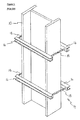
- brackets such as those shown in Figures 1 and 2 , are commonly used.
- the I-beam 10 has trunking 12 attached to it using brackets 14.
- the brackets 14 are formed from pairs of U-section steel 16 that are clamped into engagement with beam 10 using threaded rods 18 and nuts (not shown).
- brackets and trunking extend far outside the area confined within the cross-section of the pillar and in particular, the brackets 14 represent a significant snag hazard for people or objects passing in close proximity to the brackets.
- Preferred embodiments of the present invention seek to overcome the above described disadvantages of the prior art.
- an apparatus for connecting elongate members to a structural support member having a channel therein comprising:-
- the advantage is provided that sections of trunking and/or conduit can be attached to such a beam and be contained substantially or entirely within the channel of the beam.
- a support member such as a beam or pillar
- the likelihood of damage to objects or people passing close to the pillar is significantly reduced.
- the likelihood of the trunking or conduit being damaged is also significantly reduced. In clean environments, this is particularly important since damage to trunking conduit can increase the number of dirt traps and can also allow ingress of water into the regularly cleaned trunking, as a result of the damage. It is also the case that, the above described bracket is itself significantly easier to clean than those of the prior art, making it more suitable for use in clean environments.
- a surface engaging portion is fixedly connected to said body.
- the surface engaging portions comprise a pair of surface engaging portions each moveable relative to said body.
- At least one surface engaging portion is connected to said body by a respective leg.
- bracket of the present invention can be used over a wide range of sizes of beam with significantly varying distances between the opposing surfaces of the beam.
- At least one leg comprises a threaded portion adapted to engage a reciprocal threaded portion formed in said body.
- the apparatus may further comprise at least one locking nut for engaging said threaded portion on said leg and locking said leg relative to said body.
- the advantage is provided that the position of the surface engaging portions, and therefore the force they are applying to the opposing surfaces of the support beam, can be fixed and will not alter over time.
- the apparatus may further comprise at least one cover extending at least partially over said body portion and at least partially over at least one leg portion.
- the cover is adapted to be cut to length to substantially cover the width of the channel between the opposing surfaces.
- the apparatus of the present invention is particularly adaptable to using in many different sizes of beam whilst still providing a very high standard of hygiene and easy cleaning surfaces where the apparatus of the present invention is used in a clean environment.
- the other components can be formed from less expensive and easier to work materials that are required for clean environments, since they are protected by the cover.
- a construction apparatus comprising:-
- At least one said elongate member comprises a section of trunking and/or conduit.
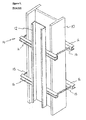
- an apparatus in the form of bracket 20 is used for connecting elongate members, such as trunking section 12, to a structural support beam 10.
- beam and pillar are used interchangeably.
- the present invention is suitable for use equally on beams and pillar, although would more commonly be used on vertically oriented pillars.
- the beam 10 shown in Figures 4 and 5 is a so-called I-beam having a pair of flanges 22 connected by a web 24.
- the beam is an I-beam because the web 24, when viewed in cross-section, is longer than either of the flanges 22.
- the present invention is equally applicable for use with other beams, for example an H-beam (where the flanges are longer than the web) or a U- or C-beam.
- the beam is provided with a channel 26, extending along the length of the beam and formed from opposing surfaces 28 and 30 of the flanges and surface 32 of the web.
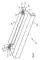
- Bracket 20 includes a pair of surface engaging portions 34 and 36 that engage the opposing flange surfaces 28 and 30 in channel 26 of beam 10. Bracket 20 also has a body 38 that is formed from a piece of U-section steel that has had ends 40 attached thereto. Each end 40 has a threaded aperture 42 into which is received a leg 44 formed with a thread 46 that engages the thread in aperture 42.
- Each leg 44 is fixedly connected to a surface engaging portion 34, 36, so that rotation of the surface engaging portion causes that portion to move towards or away from body 38.
- the legs 44 are preferably just less than half the length of the body 38 so as to provide the maximum adjustment between the smallest position, where the majority of the leg is contained within body 38, and the largest condition when the majority of the leg is external to body 38.
- Each leg 44 is also provided with a locking nut 48 that can be used to lock the position of the leg relative to body 38 by rotation of the locking nut so that it is engaged with end 40.
- cover piece 50 which is a piece of U-section steel that attaches to and covers the body 38 as well as covering the legs 44 and surface engaging portions 34 and 36 of bracket 20.
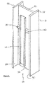
- Body 38 is located between flange surfaces 28 and 30 in beam 10 and surface engaging portions 34 and 36 are rotated until they are almost in engagement with the flange surfaces.
- the legs 44 are further extended by rotation of surface engaging portions 34 and 36 by the use of a spanner in conjunction with hexagonal tool engaging portions 52 that are located immediately behind the surface engaging portions 34 and 36.
- the hexagonal engaging portions 52 of surface engaging portions 34 and 36 are rotated until sufficient force is being applied to the flange surfaces not only to hold the bracket 20 but also the trunking to be attached thereto.
- the locking nuts 48 are rotated, typically using the same spanner as previously mentioned, until they are in locked engagement with ends 40 of body 38.
- Cover 50 is then placed over the body 38, as well as legs 44 and surface engaging portions 34 and 36.
- the cover 50 is fixed into place by any suitable means, for example, body 38 can be formed from a length of U-section steel having a lip 54 along each edge as shown in Figure 6 .
- This material commonly referred to as "strut”
- strut has a rectangular sprung nut 56 inserted into the channel, in the orientation shown in Figure 6 , and rotated by 90° so that the edges 58, which are generally formed with indentations, grip or cut into lips 54.
- the edges 58 are pressed into engagement with lips 54 by spring 60 which presses against rear wall 62 of body 38.
- the threaded aperture 64 in spring nut 56 receives bolts (not shown) that extend through apertures (also not shown) in the cover 50.
- Trunking 12 or other elongate member is then attached to the bracket 20. Most typically several brackets are attached to the beam 10 and then the trunking 12 is attached to multiple brackets.
- the connection between trunking 12 and bracket 20 is by any suitable means.
- the cover 50 can be provided with threaded holes that receive bolts that extend through non-threaded holes in sections of trunking.
- the non-threaded holes in the trunking 12 could be aligned with the holes in the cover 50 and bolts then engage the threaded apertures 64 in sprung nuts 56.
- the sprung nut 56 could be a sprung bolt that extends through a hole in the cover and/or trunking and a non-sprung nut attached thereto.
- devices such as conduit saddles or the like are fixed to the threaded holes in cover 50 or in sprung nut 56.
- the trunking 12 can be recessed completely within the cross-sectional area of channel 26.
- the components described above are preferably made from stainless steel.
- any other suitably strong material could also be used.
- some non-structural components, for example cover 50 may be formed from material such as plastic. It is also the case that the surface engaging portions 34 and 36 may be coated with a suitable material to provide additional grip when pressed into engagement with the surfaces 28 and 30 of channel 26.
- one end of the body 38 could be provided without the leg 44 and the surface engaging portion formed directly or stuck directly to the end 40.
- the other surface engaging portion would be adjustable as described above and would therefore provide sufficient adjustment.
- the cover 50 could be excluded and the bracket 20 still operate to carry the trunking 12.
Landscapes
- Engineering & Computer Science (AREA)
- General Engineering & Computer Science (AREA)
- Mechanical Engineering (AREA)
- Architecture (AREA)
- Civil Engineering (AREA)
- Structural Engineering (AREA)
- Supports For Pipes And Cables (AREA)
Abstract
Description
- The present invention relates to construction apparatus and to apparatus for connecting elongate members to a structural support beam or pillar, and relates particularly, but not exclusively, to a system for attaching trunking and conduit to an H- or I-beam for use in clean environments.
- The use of trunking and conduit to protect electrical cables is well known and is used in many industries. In clean environments, such as those of the food and beverage preparation and pharmaceutical industries, it is commonplace to use trunking and conduit formed from stainless steel thereby giving it easy to clean surfaces. Such trunking and conduit systems have as many smooth and easy to clean surfaces as possible, and wherever feasible, eliminate tight corners, non-close fitting junctions and other dirt traps.
- Many industrial buildings are constructed using a steel beam frame formed from rolled steel members having an "H" or "I" shaped cross-section. When such members are commonly referred to I-beams or H-beams although when forming a vertical support member are referred to as pillars. It is also commonplace for these beams to be left exposed within a building and to be used to conveniently carry sections of conduit and trunking as well as other utility supplies including cable trays, gas pipes and air lines. In order to maintain the integrity of the beam or pillar it is invariably the case that drilling holes through the ends or flange of the beam is forbidden. As a result, to attach trunking conduit or the other utilities mentioned to a beam or pillar, brackets, such as those shown in
Figures 1 and2 , are commonly used. In these examples, the I-beam 10 has trunking 12 attached to it usingbrackets 14. Thebrackets 14 are formed from pairs ofU-section steel 16 that are clamped into engagement withbeam 10 using threadedrods 18 and nuts (not shown). - Such apparatus is particularly difficult to clean and is prone to collecting dirt. As a result, it is unsuitable for use in clean environments. Furthermore, when attached to a pillar the brackets and trunking extend far outside the area confined within the cross-section of the pillar and in particular, the
brackets 14 represent a significant snag hazard for people or objects passing in close proximity to the brackets. - Preferred embodiments of the present invention seek to overcome the above described disadvantages of the prior art.
- According to an aspect of the present invention, there is provided an apparatus for connecting elongate members to a structural support member having a channel therein, the apparatus comprising:-
- surface engaging portions for engaging opposing surfaces of a channel formed in a structural support member ;
- at least one body portion connected to said surface engaging portion such that at least one surface engaging portion can be moved relative to said body such that said surface engaging portions can be moved in opposite directions to apply a gripping force to said opposing surfaces of said beam;
- at least one connecting portion for connecting said body to one or more elongate members.
- By providing a bracket that engages opposing surfaces of a channel formed in a support member, such as a beam or pillar, the advantage is provided that sections of trunking and/or conduit can be attached to such a beam and be contained substantially or entirely within the channel of the beam. As a result, the likelihood of damage to objects or people passing close to the pillar is significantly reduced. Furthermore, the likelihood of the trunking or conduit being damaged is also significantly reduced. In clean environments, this is particularly important since damage to trunking conduit can increase the number of dirt traps and can also allow ingress of water into the regularly cleaned trunking, as a result of the damage. It is also the case that, the above described bracket is itself significantly easier to clean than those of the prior art, making it more suitable for use in clean environments.
- In a preferred embodiment a surface engaging portion is fixedly connected to said body.
- In another preferred embodiment the surface engaging portions comprise a pair of surface engaging portions each moveable relative to said body.
- In a further preferred embodiment at least one surface engaging portion is connected to said body by a respective leg.
- By making both surface engaging portions movable relative to the body, and particularly by doing so with a pair of movable legs, the advantage is provided that the bracket of the present invention can be used over a wide range of sizes of beam with significantly varying distances between the opposing surfaces of the beam.
- In a preferred embodiment at least one leg comprises a threaded portion adapted to engage a reciprocal threaded portion formed in said body.
- By using threaded portions to connect the body to the surface engaging portion, the advantage is provided that a simple mechanism is provided to alter the separation between the surface engaging portions.
- The apparatus may further comprise at least one locking nut for engaging said threaded portion on said leg and locking said leg relative to said body.
- By providing a locking nut, the advantage is provided that the position of the surface engaging portions, and therefore the force they are applying to the opposing surfaces of the support beam, can be fixed and will not alter over time.
- The apparatus may further comprise at least one cover extending at least partially over said body portion and at least partially over at least one leg portion.
- In a preferred embodiment the cover is adapted to be cut to length to substantially cover the width of the channel between the opposing surfaces.
- By providing a cover portion, and in particular one that can be cut to the required length, the advantage is provided that the apparatus of the present invention is particularly adaptable to using in many different sizes of beam whilst still providing a very high standard of hygiene and easy cleaning surfaces where the apparatus of the present invention is used in a clean environment. Furthermore, where a cover is used, the other components can be formed from less expensive and easier to work materials that are required for clean environments, since they are protected by the cover.
- According to another aspect of the present invention, there is provided a construction apparatus comprising:-
- at least one elongate member;
- a plurality of apparatus for connecting said elongate member to a structural support member having a channel therein, as set out above; and
- fixing means for fixing said elongate member to said apparatus.
- In a preferred embodiment at least one said elongate member comprises a section of trunking and/or conduit.
- Preferred embodiments of the present invention will now be described, by way of example only, and not in any limitative sense, with reference to the accompanying drawings in which:-
-
Figures 1 and2 are perspective views of apparatus of the prior art; -
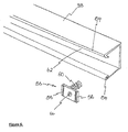
Figure 3 is a perspective view of an apparatus of the present invention; -
Figure 4 is a perspective view of the apparatus ofFigure 3 in use on an I-beam, including a partial cut-away section of the beam; -
Figure 5 is a perspective view of the apparatus ofFigure 3 in use; and -
Figure 6 is a perspective view of a portion of the apparatus ofFigure 3 . - Referring to
Figures 3 to 5 , an apparatus, in the form ofbracket 20 is used for connecting elongate members, such astrunking section 12, to astructural support beam 10. It should be note that throughout the present application the terms beam and pillar are used interchangeably. The present invention is suitable for use equally on beams and pillar, although would more commonly be used on vertically oriented pillars. Thebeam 10 shown inFigures 4 and5 is a so-called I-beam having a pair offlanges 22 connected by aweb 24. In this example, the beam is an I-beam because theweb 24, when viewed in cross-section, is longer than either of theflanges 22. The present invention is equally applicable for use with other beams, for example an H-beam (where the flanges are longer than the web) or a U- or C-beam. In each of the examples, the beam is provided with achannel 26, extending along the length of the beam and formed fromopposing surfaces surface 32 of the web. -
Bracket 20 includes a pair ofsurface engaging portions opposing flange surfaces channel 26 ofbeam 10.Bracket 20 also has abody 38 that is formed from a piece of U-section steel that has hadends 40 attached thereto. Eachend 40 has a threaded aperture 42 into which is received aleg 44 formed with athread 46 that engages the thread in aperture 42. - Each
leg 44 is fixedly connected to asurface engaging portion body 38. Thelegs 44 are preferably just less than half the length of thebody 38 so as to provide the maximum adjustment between the smallest position, where the majority of the leg is contained withinbody 38, and the largest condition when the majority of the leg is external to body 38.Eachleg 44 is also provided with alocking nut 48 that can be used to lock the position of the leg relative tobody 38 by rotation of the locking nut so that it is engaged withend 40. - For attaching to
bracket 20 there is provided acover piece 50 which is a piece of U-section steel that attaches to and covers thebody 38 as well as covering thelegs 44 andsurface engaging portions bracket 20. - Use of the
brackets 20 will now be described.Body 38 is located betweenflange surfaces beam 10 andsurface engaging portions legs 44 are further extended by rotation ofsurface engaging portions tool engaging portions 52 that are located immediately behind thesurface engaging portions engaging portions 52 ofsurface engaging portions bracket 20 but also the trunking to be attached thereto. Once thebracket 20 is in place, thelocking nuts 48 are rotated, typically using the same spanner as previously mentioned, until they are in locked engagement withends 40 ofbody 38. -
Cover 50 is then placed over thebody 38, as well aslegs 44 andsurface engaging portions cover 50 is fixed into place by any suitable means, for example,body 38 can be formed from a length of U-section steel having alip 54 along each edge as shown inFigure 6 . This material, commonly referred to as "strut", has a rectangular sprungnut 56 inserted into the channel, in the orientation shown inFigure 6 , and rotated by 90° so that theedges 58, which are generally formed with indentations, grip or cut intolips 54. Theedges 58 are pressed into engagement withlips 54 byspring 60 which presses againstrear wall 62 ofbody 38. The threadedaperture 64 inspring nut 56 receives bolts (not shown) that extend through apertures (also not shown) in thecover 50. -
Trunking 12 or other elongate member is then attached to thebracket 20. Most typically several brackets are attached to thebeam 10 and then thetrunking 12 is attached to multiple brackets. The connection betweentrunking 12 andbracket 20 is by any suitable means. For example thecover 50 can be provided with threaded holes that receive bolts that extend through non-threaded holes in sections of trunking. Alternatively the non-threaded holes in thetrunking 12 could be aligned with the holes in thecover 50 and bolts then engage the threadedapertures 64 in sprung nuts 56. As a further alternative the sprungnut 56 could be a sprung bolt that extends through a hole in the cover and/or trunking and a non-sprung nut attached thereto. Where the bracket is being used to hold sections of conduit or other tubing, devices such as conduit saddles or the like are fixed to the threaded holes incover 50 or in sprungnut 56. - Depending upon the dimensions of the trunking and the dimensions of the beam, the
trunking 12 can be recessed completely within the cross-sectional area ofchannel 26. - It will be appreciated by persons skilled in the art that the above embodiments have been described by way of example only and not in any limitative sense, and that the various alterations and modifications are possible without departure from the scope of the invention as defined by the appended claims. For example, the components described above are preferably made from stainless steel. However, any other suitably strong material could also be used. Furthermore, some non-structural components, for
example cover 50, may be formed from material such as plastic. It is also the case that thesurface engaging portions surfaces channel 26. - As a further alternative, one end of the
body 38 could be provided without theleg 44 and the surface engaging portion formed directly or stuck directly to theend 40. The other surface engaging portion would be adjustable as described above and would therefore provide sufficient adjustment. Furthermore, in environments where easy clean surfaces are not paramount, thecover 50 could be excluded and thebracket 20 still operate to carry thetrunking 12.
Claims (10)
- An apparatus for connecting elongate members to a structural support member having a channel therein, the apparatus comprising:-surface engaging portions for engaging opposing surfaces of a channel formed in a structural support member;at least one body portion connected to said surface engaging portion such that at least one surface engaging portion can be moved relative to said body such that said surface engaging portions can be moved in opposite directions to apply a gripping force to said opposing surfaces of said beam;at least one connecting portion for connecting said body to one or more elongate members.
- An apparatus according to claim 1, wherein a surface engaging portion is fixedly connected to said body.
- An apparatus according to claim 1, wherein said surface engaging portions comprise a pair of surface engaging portions each moveable relative to said body.
- An apparatus according to any of the preceding claims, wherein at least one surface engaging portion is connected to said body by a respective leg.
- An apparatus according to claim 4, wherein at least one leg comprises a threaded portion adapted to engage a reciprocal threaded portion formed in said body.
- An apparatus according to claim 5, further comprising at least one locking nut for engaging said threaded portion on said leg and locking said leg relative to said body.
- An apparatus according to any of the preceding claims, further comprising at least one cover extending at least partially over said body portion and at least partially over at least one leg portion.
- An apparatus according to claim 7, wherein said cover is adapted to be cut to length to substantially cover the width of the channel between the opposing surfaces.
- A construction apparatus comprising:-at least one elongate member;a plurality of apparatus for connecting said elongate member to a structural support member having a channel therein, according to any of the preceding claims; andfixing means for fixing said elongate member to said apparatus.
- An apparatus according to claim 10, wherein at least one said elongate member comprises a section of trunking and/or conduit.
Applications Claiming Priority (1)
| Application Number | Priority Date | Filing Date | Title |
|---|---|---|---|
| GB1309751.4A GB2514613B (en) | 2013-05-31 | 2013-05-31 | Construction apparatus |
Publications (1)
| Publication Number | Publication Date |
|---|---|
| EP2808564A1 true EP2808564A1 (en) | 2014-12-03 |
Family
ID=48805550
Family Applications (1)
| Application Number | Title | Priority Date | Filing Date |
|---|---|---|---|
| EP14154544.2A Withdrawn EP2808564A1 (en) | 2013-05-31 | 2014-02-10 | Length adjustable construction apparatus |
Country Status (2)
| Country | Link |
|---|---|
| EP (1) | EP2808564A1 (en) |
| GB (1) | GB2514613B (en) |
Cited By (2)
| Publication number | Priority date | Publication date | Assignee | Title |
|---|---|---|---|---|
| WO2019204924A1 (en) * | 2018-04-24 | 2019-10-31 | Bermanfalk Hospitality Group Llp | Method and system for securing mini-fridge |
| US20250043565A1 (en) * | 2023-07-31 | 2025-02-06 | Alpin Management Partners Ltd | Beam Mounting Bracket |
Citations (4)
| Publication number | Priority date | Publication date | Assignee | Title |
|---|---|---|---|---|
| US4729532A (en) * | 1985-04-23 | 1988-03-08 | Billy Moss | Safety valve anchoring device |
| US20030198520A1 (en) * | 2002-04-22 | 2003-10-23 | Evans Daniel D. | Conduit retainer apparatus |
| FR2902844A1 (en) * | 2006-06-23 | 2007-12-28 | Philippe Turlier | FIXING DEVICE FOR LUMINAIRE |
| GB2482537A (en) * | 2010-08-05 | 2012-02-08 | Wesley Thompson Lynn | Beam clamp |
Family Cites Families (7)
| Publication number | Priority date | Publication date | Assignee | Title |
|---|---|---|---|---|
| US4717099A (en) * | 1986-05-15 | 1988-01-05 | Hubbard George R | Fire sprinkler alignment bracket |
| GB0004520D0 (en) * | 2000-02-26 | 2000-04-19 | Rigby Wilfred O | Fixing bracket for steelwork |
| US7506845B2 (en) * | 2006-10-05 | 2009-03-24 | Kofulso Co., Ltd | Stock bar and horizontal bar coupling device for mounting sprinkler |
| US7845599B2 (en) * | 2007-03-22 | 2010-12-07 | The Viking Corporation | Mounting coupling for sprinkler support system |
| US8714495B2 (en) * | 2009-05-27 | 2014-05-06 | Philip Allen Myers | Building strut system |
| FR2962716B1 (en) * | 2010-07-13 | 2013-08-02 | Airbus Operations Sas | FIXING ASSEMBLY COMPRISING RAMPS FOR FASTENING SYSTEMS ON AIRCRAFT FRAMES. |
| EP2587105A1 (en) * | 2011-10-27 | 2013-05-01 | Zurecon Ag | Pipe clip |
-
2013
- 2013-05-31 GB GB1309751.4A patent/GB2514613B/en active Active
-
2014
- 2014-02-10 EP EP14154544.2A patent/EP2808564A1/en not_active Withdrawn
Patent Citations (4)
| Publication number | Priority date | Publication date | Assignee | Title |
|---|---|---|---|---|
| US4729532A (en) * | 1985-04-23 | 1988-03-08 | Billy Moss | Safety valve anchoring device |
| US20030198520A1 (en) * | 2002-04-22 | 2003-10-23 | Evans Daniel D. | Conduit retainer apparatus |
| FR2902844A1 (en) * | 2006-06-23 | 2007-12-28 | Philippe Turlier | FIXING DEVICE FOR LUMINAIRE |
| GB2482537A (en) * | 2010-08-05 | 2012-02-08 | Wesley Thompson Lynn | Beam clamp |
Cited By (2)
| Publication number | Priority date | Publication date | Assignee | Title |
|---|---|---|---|---|
| WO2019204924A1 (en) * | 2018-04-24 | 2019-10-31 | Bermanfalk Hospitality Group Llp | Method and system for securing mini-fridge |
| US20250043565A1 (en) * | 2023-07-31 | 2025-02-06 | Alpin Management Partners Ltd | Beam Mounting Bracket |
Also Published As
| Publication number | Publication date |
|---|---|
| GB2514613A (en) | 2014-12-03 |
| GB201309751D0 (en) | 2013-07-17 |
| GB2514613B (en) | 2015-12-09 |
Similar Documents
| Publication | Publication Date | Title |
|---|---|---|
| US10161127B2 (en) | Fitting for channel framing | |
| US9790980B2 (en) | Fastener nut for channel framing | |
| EP3784940B1 (en) | Pipe support clamp | |
| US8480041B2 (en) | Beam clamp | |
| US9670949B1 (en) | Keyhole weld-down fastener base | |
| CA2890064C (en) | Trapeze hanger system including twist-locking fitting | |
| US12000510B2 (en) | Sway brace attachment | |
| US11060638B2 (en) | Fitting for brace member | |
| KR102714948B1 (en) | Seismic clamp for non-structural components in a building | |
| US11125383B1 (en) | Adjustable support device for bay windows and other protruding building structures | |
| EP3132102A1 (en) | Vertical cable rail barrier | |
| EP2808564A1 (en) | Length adjustable construction apparatus | |
| US6783104B1 (en) | Deformable clamp employed to stiffen hanger rod | |
| US10851917B2 (en) | Seismic clamp for non-structural components in a building | |
| US20120012715A1 (en) | Systems, methods, and apparatus for providing a metal clad cable clamp | |
| US20160069480A1 (en) | Cord support bracket | |
| US12134499B1 (en) | Skid apparatus, system and method | |
| EP2198100B1 (en) | A post and a structure comprising a post | |
| US10760323B1 (en) | Adjustable support device for bay windows and other protruding building structures | |
| US20250075490A1 (en) | Hanger assembly for use on open web steel joists or beams | |
| US11346468B1 (en) | Adjustable support apparatus and method of use | |
| NZ726961B2 (en) | Pipe clips and brackets therefor |
Legal Events
| Date | Code | Title | Description |
|---|---|---|---|
| PUAI | Public reference made under article 153(3) epc to a published international application that has entered the european phase |
Free format text: ORIGINAL CODE: 0009012 |
|
| 17P | Request for examination filed |
Effective date: 20140210 |
|
| AK | Designated contracting states |
Kind code of ref document: A1 Designated state(s): AL AT BE BG CH CY CZ DE DK EE ES FI FR GB GR HR HU IE IS IT LI LT LU LV MC MK MT NL NO PL PT RO RS SE SI SK SM TR |
|
| AX | Request for extension of the european patent |
Extension state: BA ME |
|
| R17P | Request for examination filed (corrected) |
Effective date: 20150603 |
|
| RBV | Designated contracting states (corrected) |
Designated state(s): AL AT BE BG CH CY CZ DE DK EE ES FI FR GB GR HR HU IE IS IT LI LT LU LV MC MK MT NL NO PL PT RO RS SE SI SK SM TR |
|
| 17Q | First examination report despatched |
Effective date: 20161107 |
|
| STAA | Information on the status of an ep patent application or granted ep patent |
Free format text: STATUS: THE APPLICATION IS DEEMED TO BE WITHDRAWN |
|
| 18D | Application deemed to be withdrawn |
Effective date: 20170518 |