EP2808536B1 - Engine control unit - Google Patents
Engine control unit Download PDFInfo
- Publication number
- EP2808536B1 EP2808536B1 EP14170129.2A EP14170129A EP2808536B1 EP 2808536 B1 EP2808536 B1 EP 2808536B1 EP 14170129 A EP14170129 A EP 14170129A EP 2808536 B1 EP2808536 B1 EP 2808536B1
- Authority
- EP
- European Patent Office
- Prior art keywords
- grade
- state
- road
- idling
- stop
- Prior art date
- Legal status (The legal status is an assumption and is not a legal conclusion. Google has not performed a legal analysis and makes no representation as to the accuracy of the status listed.)
- Active
Links
Images

Classifications
-
- F—MECHANICAL ENGINEERING; LIGHTING; HEATING; WEAPONS; BLASTING
- F02—COMBUSTION ENGINES; HOT-GAS OR COMBUSTION-PRODUCT ENGINE PLANTS
- F02N—STARTING OF COMBUSTION ENGINES; STARTING AIDS FOR SUCH ENGINES, NOT OTHERWISE PROVIDED FOR
- F02N11/00—Starting of engines by means of electric motors
- F02N11/08—Circuits or control means specially adapted for starting of engines
- F02N11/0814—Circuits or control means specially adapted for starting of engines comprising means for controlling automatic idle-start-stop
- F02N11/0818—Conditions for starting or stopping the engine or for deactivating the idle-start-stop mode
- F02N11/0833—Vehicle conditions
- F02N11/0837—Environmental conditions thereof, e.g. traffic, weather or road conditions
-
- B—PERFORMING OPERATIONS; TRANSPORTING
- B60—VEHICLES IN GENERAL
- B60W—CONJOINT CONTROL OF VEHICLE SUB-UNITS OF DIFFERENT TYPE OR DIFFERENT FUNCTION; CONTROL SYSTEMS SPECIALLY ADAPTED FOR HYBRID VEHICLES; ROAD VEHICLE DRIVE CONTROL SYSTEMS FOR PURPOSES NOT RELATED TO THE CONTROL OF A PARTICULAR SUB-UNIT
- B60W10/00—Conjoint control of vehicle sub-units of different type or different function
- B60W10/04—Conjoint control of vehicle sub-units of different type or different function including control of propulsion units
- B60W10/06—Conjoint control of vehicle sub-units of different type or different function including control of propulsion units including control of combustion engines
-
- B—PERFORMING OPERATIONS; TRANSPORTING
- B60—VEHICLES IN GENERAL
- B60W—CONJOINT CONTROL OF VEHICLE SUB-UNITS OF DIFFERENT TYPE OR DIFFERENT FUNCTION; CONTROL SYSTEMS SPECIALLY ADAPTED FOR HYBRID VEHICLES; ROAD VEHICLE DRIVE CONTROL SYSTEMS FOR PURPOSES NOT RELATED TO THE CONTROL OF A PARTICULAR SUB-UNIT
- B60W10/00—Conjoint control of vehicle sub-units of different type or different function
- B60W10/18—Conjoint control of vehicle sub-units of different type or different function including control of braking systems
-
- B—PERFORMING OPERATIONS; TRANSPORTING
- B60—VEHICLES IN GENERAL
- B60W—CONJOINT CONTROL OF VEHICLE SUB-UNITS OF DIFFERENT TYPE OR DIFFERENT FUNCTION; CONTROL SYSTEMS SPECIALLY ADAPTED FOR HYBRID VEHICLES; ROAD VEHICLE DRIVE CONTROL SYSTEMS FOR PURPOSES NOT RELATED TO THE CONTROL OF A PARTICULAR SUB-UNIT
- B60W10/00—Conjoint control of vehicle sub-units of different type or different function
- B60W10/30—Conjoint control of vehicle sub-units of different type or different function including control of auxiliary equipment, e.g. air-conditioning compressors or oil pumps
-
- B—PERFORMING OPERATIONS; TRANSPORTING
- B60—VEHICLES IN GENERAL
- B60W—CONJOINT CONTROL OF VEHICLE SUB-UNITS OF DIFFERENT TYPE OR DIFFERENT FUNCTION; CONTROL SYSTEMS SPECIALLY ADAPTED FOR HYBRID VEHICLES; ROAD VEHICLE DRIVE CONTROL SYSTEMS FOR PURPOSES NOT RELATED TO THE CONTROL OF A PARTICULAR SUB-UNIT
- B60W30/00—Purposes of road vehicle drive control systems not related to the control of a particular sub-unit, e.g. of systems using conjoint control of vehicle sub-units, or advanced driver assistance systems for ensuring comfort, stability and safety or drive control systems for propelling or retarding the vehicle
- B60W30/18—Propelling the vehicle
- B60W30/18009—Propelling the vehicle related to particular drive situations
- B60W30/18072—Coasting
-
- F—MECHANICAL ENGINEERING; LIGHTING; HEATING; WEAPONS; BLASTING
- F02—COMBUSTION ENGINES; HOT-GAS OR COMBUSTION-PRODUCT ENGINE PLANTS
- F02N—STARTING OF COMBUSTION ENGINES; STARTING AIDS FOR SUCH ENGINES, NOT OTHERWISE PROVIDED FOR
- F02N11/00—Starting of engines by means of electric motors
- F02N11/08—Circuits or control means specially adapted for starting of engines
- F02N11/0814—Circuits or control means specially adapted for starting of engines comprising means for controlling automatic idle-start-stop
- F02N11/0818—Conditions for starting or stopping the engine or for deactivating the idle-start-stop mode
- F02N11/0825—Conditions for starting or stopping the engine or for deactivating the idle-start-stop mode related to prevention of engine restart failure, e.g. disabling automatic stop at low battery state
-
- F—MECHANICAL ENGINEERING; LIGHTING; HEATING; WEAPONS; BLASTING
- F02—COMBUSTION ENGINES; HOT-GAS OR COMBUSTION-PRODUCT ENGINE PLANTS
- F02N—STARTING OF COMBUSTION ENGINES; STARTING AIDS FOR SUCH ENGINES, NOT OTHERWISE PROVIDED FOR
- F02N11/00—Starting of engines by means of electric motors
- F02N11/10—Safety devices
- F02N11/108—Safety devices for diagnosis of the starter or its components
-
- B—PERFORMING OPERATIONS; TRANSPORTING
- B60—VEHICLES IN GENERAL
- B60W—CONJOINT CONTROL OF VEHICLE SUB-UNITS OF DIFFERENT TYPE OR DIFFERENT FUNCTION; CONTROL SYSTEMS SPECIALLY ADAPTED FOR HYBRID VEHICLES; ROAD VEHICLE DRIVE CONTROL SYSTEMS FOR PURPOSES NOT RELATED TO THE CONTROL OF A PARTICULAR SUB-UNIT
- B60W30/00—Purposes of road vehicle drive control systems not related to the control of a particular sub-unit, e.g. of systems using conjoint control of vehicle sub-units, or advanced driver assistance systems for ensuring comfort, stability and safety or drive control systems for propelling or retarding the vehicle
- B60W30/18—Propelling the vehicle
- B60W30/18009—Propelling the vehicle related to particular drive situations
- B60W30/18072—Coasting
- B60W2030/18081—With torque flow from driveshaft to engine, i.e. engine being driven by vehicle
-
- B—PERFORMING OPERATIONS; TRANSPORTING
- B60—VEHICLES IN GENERAL
- B60W—CONJOINT CONTROL OF VEHICLE SUB-UNITS OF DIFFERENT TYPE OR DIFFERENT FUNCTION; CONTROL SYSTEMS SPECIALLY ADAPTED FOR HYBRID VEHICLES; ROAD VEHICLE DRIVE CONTROL SYSTEMS FOR PURPOSES NOT RELATED TO THE CONTROL OF A PARTICULAR SUB-UNIT
- B60W2520/00—Input parameters relating to overall vehicle dynamics
- B60W2520/10—Longitudinal speed
-
- B—PERFORMING OPERATIONS; TRANSPORTING
- B60—VEHICLES IN GENERAL
- B60W—CONJOINT CONTROL OF VEHICLE SUB-UNITS OF DIFFERENT TYPE OR DIFFERENT FUNCTION; CONTROL SYSTEMS SPECIALLY ADAPTED FOR HYBRID VEHICLES; ROAD VEHICLE DRIVE CONTROL SYSTEMS FOR PURPOSES NOT RELATED TO THE CONTROL OF A PARTICULAR SUB-UNIT
- B60W2540/00—Input parameters relating to occupants
- B60W2540/12—Brake pedal position
-
- B—PERFORMING OPERATIONS; TRANSPORTING
- B60—VEHICLES IN GENERAL
- B60W—CONJOINT CONTROL OF VEHICLE SUB-UNITS OF DIFFERENT TYPE OR DIFFERENT FUNCTION; CONTROL SYSTEMS SPECIALLY ADAPTED FOR HYBRID VEHICLES; ROAD VEHICLE DRIVE CONTROL SYSTEMS FOR PURPOSES NOT RELATED TO THE CONTROL OF A PARTICULAR SUB-UNIT
- B60W2552/00—Input parameters relating to infrastructure
- B60W2552/15—Road slope
-
- B—PERFORMING OPERATIONS; TRANSPORTING
- B60—VEHICLES IN GENERAL
- B60W—CONJOINT CONTROL OF VEHICLE SUB-UNITS OF DIFFERENT TYPE OR DIFFERENT FUNCTION; CONTROL SYSTEMS SPECIALLY ADAPTED FOR HYBRID VEHICLES; ROAD VEHICLE DRIVE CONTROL SYSTEMS FOR PURPOSES NOT RELATED TO THE CONTROL OF A PARTICULAR SUB-UNIT
- B60W2710/00—Output or target parameters relating to a particular sub-units
- B60W2710/06—Combustion engines, Gas turbines
-
- F—MECHANICAL ENGINEERING; LIGHTING; HEATING; WEAPONS; BLASTING
- F02—COMBUSTION ENGINES; HOT-GAS OR COMBUSTION-PRODUCT ENGINE PLANTS
- F02N—STARTING OF COMBUSTION ENGINES; STARTING AIDS FOR SUCH ENGINES, NOT OTHERWISE PROVIDED FOR
- F02N11/00—Starting of engines by means of electric motors
- F02N11/08—Circuits or control means specially adapted for starting of engines
- F02N11/0814—Circuits or control means specially adapted for starting of engines comprising means for controlling automatic idle-start-stop
- F02N11/0818—Conditions for starting or stopping the engine or for deactivating the idle-start-stop mode
- F02N11/0833—Vehicle conditions
- F02N11/084—State of vehicle accessories, e.g. air condition or power steering
-
- F—MECHANICAL ENGINEERING; LIGHTING; HEATING; WEAPONS; BLASTING
- F02—COMBUSTION ENGINES; HOT-GAS OR COMBUSTION-PRODUCT ENGINE PLANTS
- F02N—STARTING OF COMBUSTION ENGINES; STARTING AIDS FOR SUCH ENGINES, NOT OTHERWISE PROVIDED FOR
- F02N11/00—Starting of engines by means of electric motors
- F02N11/08—Circuits or control means specially adapted for starting of engines
- F02N2011/0881—Components of the circuit not provided for by previous groups
- F02N2011/0888—DC/DC converters
-
- F—MECHANICAL ENGINEERING; LIGHTING; HEATING; WEAPONS; BLASTING
- F02—COMBUSTION ENGINES; HOT-GAS OR COMBUSTION-PRODUCT ENGINE PLANTS
- F02N—STARTING OF COMBUSTION ENGINES; STARTING AIDS FOR SUCH ENGINES, NOT OTHERWISE PROVIDED FOR
- F02N2200/00—Parameters used for control of starting apparatus
- F02N2200/08—Parameters used for control of starting apparatus said parameters being related to the vehicle or its components
- F02N2200/0807—Brake booster state
-
- F—MECHANICAL ENGINEERING; LIGHTING; HEATING; WEAPONS; BLASTING
- F02—COMBUSTION ENGINES; HOT-GAS OR COMBUSTION-PRODUCT ENGINE PLANTS
- F02N—STARTING OF COMBUSTION ENGINES; STARTING AIDS FOR SUCH ENGINES, NOT OTHERWISE PROVIDED FOR
- F02N2200/00—Parameters used for control of starting apparatus
- F02N2200/08—Parameters used for control of starting apparatus said parameters being related to the vehicle or its components
- F02N2200/0808—Steering state, e.g. state of power assisted steering
-
- F—MECHANICAL ENGINEERING; LIGHTING; HEATING; WEAPONS; BLASTING
- F02—COMBUSTION ENGINES; HOT-GAS OR COMBUSTION-PRODUCT ENGINE PLANTS
- F02N—STARTING OF COMBUSTION ENGINES; STARTING AIDS FOR SUCH ENGINES, NOT OTHERWISE PROVIDED FOR
- F02N2200/00—Parameters used for control of starting apparatus
- F02N2200/12—Parameters used for control of starting apparatus said parameters being related to the vehicle exterior
- F02N2200/124—Information about road conditions, e.g. road inclination or surface
-
- Y—GENERAL TAGGING OF NEW TECHNOLOGICAL DEVELOPMENTS; GENERAL TAGGING OF CROSS-SECTIONAL TECHNOLOGIES SPANNING OVER SEVERAL SECTIONS OF THE IPC; TECHNICAL SUBJECTS COVERED BY FORMER USPC CROSS-REFERENCE ART COLLECTIONS [XRACs] AND DIGESTS
- Y02—TECHNOLOGIES OR APPLICATIONS FOR MITIGATION OR ADAPTATION AGAINST CLIMATE CHANGE
- Y02T—CLIMATE CHANGE MITIGATION TECHNOLOGIES RELATED TO TRANSPORTATION
- Y02T10/00—Road transport of goods or passengers
- Y02T10/10—Internal combustion engine [ICE] based vehicles
- Y02T10/40—Engine management systems
-
- Y—GENERAL TAGGING OF NEW TECHNOLOGICAL DEVELOPMENTS; GENERAL TAGGING OF CROSS-SECTIONAL TECHNOLOGIES SPANNING OVER SEVERAL SECTIONS OF THE IPC; TECHNICAL SUBJECTS COVERED BY FORMER USPC CROSS-REFERENCE ART COLLECTIONS [XRACs] AND DIGESTS
- Y02—TECHNOLOGIES OR APPLICATIONS FOR MITIGATION OR ADAPTATION AGAINST CLIMATE CHANGE
- Y02T—CLIMATE CHANGE MITIGATION TECHNOLOGIES RELATED TO TRANSPORTATION
- Y02T10/00—Road transport of goods or passengers
- Y02T10/60—Other road transportation technologies with climate change mitigation effect
Definitions
- the present invention relates to a unit that controls an engine equipped in a vehicle.
- ISS control An idling stop and start control (hereinafter abbreviated as "ISS control"), one of the engine controls of a vehicle, has been developed.
- the ISS control involves an idling-stop for automatically stopping the engine if a predetermined idling-stop condition is satisfied, and an idling-start thereafter for restarting the engine if a predetermined restart condition is satisfied.
- Patent Literature 1 Japanese Patent Application Publication Laid-Open No. 2012-255383
- Patent Literature 2 Japanese Patent Application Publication Laid-Open No. 2011-196288 .
- an ISS controller (automatic stop controller) stops the idling.
- the ISS controller includes an auxiliary power unit to avoid a voltage drop in a battery upon an idling-start, and a brake unit to restrict movements of the vehicle during the stop of the engine. Any failure in the ISS controller is diagnosed during its operation.
- the idling-stop condition includes a road-grade being not higher than a second predetermined grade which is smaller than the first predetermined grade before the completion of the failure diagnosis for the ISS controller, to inhibit the idling-stop at a road-grade higher than the second predetermined grade.
- idling-stop and idling-start are performed only at the second predetermined grade or lower before the failure determination for the ISS controller.
- the normality of operations of the ISS controller is diagnosed at a low-grade road (having a grade of not higher than the second predetermined grade), to avoid or prevent unexpected movements of the vehicle regardless of a failure in the ISS controller.
- Patent Literature 2 if an idling-stop condition including the speed of the vehicle being not higher than a predetermined speed is satisfied, an idling-stop is performed. In other words, the idling-stop is started during coasting at immediately before the stop of the vehicle. This configuration can further improve the fuel efficiency.
- a condition for the initial idling-stop includes the speed of the vehicle being zero or less than another set speed which is lower than the predetermined speed. If a condition for the initial idling-start holds, the normality of the idling-stop system is diagnosed. This configuration can avoid troubles in the running vehicle under an ISS control, regardless of some abnormality in the idling-stop system before the diagnosis.
- running includes coasting described below.
- the technique of Patent literature 1 for idling-stops only in a stationary-state of the vehicle is less advantageous than the technique of Patent Literature 2 for idling-stops started during coasting.
- the technique of Patent Literature 2 for performing the initial idling-stop and finding a failure depending on not a road-grade condition but only a strict speed condition is less advantageous than the technique of Patent Literature 1 for finding a failure only at a low-grade road.
- EP 2 570 651 A2 discloses a vehicle control device that ensures a frequency of automatic stopping of an engine during deceleration of a vehicle while suppressing rolling backwards of the vehicle even if a road surface has a gradient.
- EP 2 597 291 A1 discloses an internal combustion engine of a vehicle that is automatically stopped when a first automatic stopping condition is established while the vehicle is stationary or a second automatic stopping condition is established while the vehicle travels.
- An object of the invention which has been accomplished in light of the problems described above, is to provide an engine control unit that can achieve the compatibility between easy avoidance of the unexpected behaviors of a vehicle during an idling-stop and the improved fuel efficiency.
- Another object of the invention is to provide advantageous effects that are derived from the individual features described below but not from conventional techniques.
- the engine control unit includes: an idling-stop controller to automatically stop an engine equipped in a vehicle if a coasting-state idling-stop condition or a stationary-state idling-stop condition is satisfied, the coasting-state idling-stop condition including a coasting-state of the vehicle at a speed or lower, the stationary-state idling-stop condition including a stationary-state of the vehicle; an idling-start controller to restart the engine if a restart condition is satisfied during an automatic stop of the engine by the idling-stop controller; and a road-grade acquirer to acquire a road-grade at the location of the vehicle.
- the coasting-state idling-stop condition includes the road-grade acquired by the road-grade acquirer being not higher than a first coasting-state road-grade, before an initial automatic stop of the engine by the idling-stop controller.
- the coasting-state idling-stop condition includes the road-grade acquired by the road-grade acquirer being not higher than a second coasting-state road-grade higher than the first coasting-state road-grade, after the initial automatic stop of the engine by the idling-stop controller.
- initial automatic stop of the engine refers to "the first automatic stop caused by the idling-stop controller since the manual start of the engine for launching the vehicle”.
- the first coasting-state road-grade which indicates the highest road-grade that can be deemed to be flat, is 2°, for example.
- the second coasting-state road-grade is 4°, for example.
- the stationary-state idling-stop condition includes the road-grade acquired by the road-grade acquirer being not higher than a first stationary-state road-grade higher than the first coasting-state road-grade, before the initial automatic stop of the engine by the idling-stop controller; and the stationary-state idling-stop condition includes the road-grade acquired by the road-grade acquirer being not higher than a second stationary-state road-grade higher than the first stationary-state road-grade, after the initial automatic stop of the engine by the idling-stop controller.
- the road-grade acquirer acquires a road-grade estimated based on the longitudinal acceleration of the vehicle in a stationary-state, and acquires a road-grade estimated based on the longitudinal acceleration of the vehicle and another parameter corresponding to the running state of the vehicle in a running-state.
- the engine control unit further includes a diagnoser to find some abnormality in devices operating during an automatic stop of the engine or a restarts of the engine, and the idling-start controller restarts the engine if the diagnoser finds some abnormality in the devices operating during an automatic stop of the engine or a restart of the engine, during the automatic stop of the engine. This restart process is executed even if the restart condition is not satisfied.
- the idling-stop controller inhibits an automatic stop of the engine if the diagnoser finds some abnormality in the devices operating during an automatic stop of the engine or a restart of the engine.
- the devices operating during an automatic stop of the engine or a restart of the engine include a stationary-state retainer to maintain braking force to the vehicle for keeping its stationary-state, during an automatic stop of the engine of the vehicle in the stationary-state.
- the coasting-state idling-stop condition includes, for example, a road-grade acquired by the road-grade acquirer being not higher than the first coasting-state road-grade (i.e., the highest road-grade that can be deemed to be flat), before an initial automatic stop of the engine by the idling-stop controller. That is, the initial automatic stop of the engine in a coasting-state of the vehicle is performed at the first coasting-state road-grade or lower.
- This configuration can readily avoid the unexpected behaviors of the vehicle during an automatic stop of the engine, regardless of some abnormality in devices in the engine control unit.
- the coasting-state idling-stop condition includes a road-grade acquired by the road-grade acquirer being not higher than the second coasting-state road-grade higher than the first coasting-state road-grade, after the initial automatic stop of the engine. That is, the engine can be automatically stopped in a coasting-state of the vehicle at a road-grade not higher than the second coasting-state road-grade higher than the first coasting-state road-grade, after the initial automatic stop of the engine.
- automatic stops of the engine are available in the coasting-state at not only flat roads but also slopes having the second coasting-state road-grade or lower, after the initial automatic stop of the engine. This configuration can increase the frequency of automatic stops of the engine in the coasting-state, to improve the fuel efficiency.
- the invention thus can readily avoid the unexpected behaviors of the vehicle during an automatic stop of the engine, and increase the frequency of automatic stops of the engine to improve the fuel efficiency.
- the engine control unit according to the embodiment is equipped in a vehicle.
- vehicle examples include small cars, such as passenger cars, and large cars, such as trucks and buses.
- the engine control unit performs an idling stop and start control (hereinafter abbreviated as "ISS control").
- ISS control an idling stop and start control
- the engine control unit performs an idling-stop to automatically stop an engine 1 if an idling-stop condition holds, and performs an idling-start (engine restart) to restart the engine 1 if a restart condition holds during the idling-stop.
- the engine control unit includes an electronic control unit (ECU) 10.
- the ECU 10 includes a large scale integration (LSI) device or an embedded electronic device into which a microprocessor, a read only memory (ROM), and a random access memory (RAM) are integrated.
- LSI large scale integration
- ROM read only memory
- RAM random access memory
- the output of the ECU 10 is connected to devices 1 and 3 to 5, which are controlled by the ECU 10 and are supplied with power from a battery 2.
- the input of the ECU 10 is connected to sensors 6 to 9 for detecting information necessary for the ISS control and its accompanying controls.
- the input of the ECU 10 is also connected to an ignition switch (ignition SW) 20.
- the engine control unit encompasses the ECU 10, the devices 1 to 5 on its output side, and the sensors 6 to 9 on its input side.
- the devices 1 to 5 on the output side of the ECU 10 will now be described.
- the engine 1 is an internal combustion engine under the ISS control.
- the engine 1 is provided with a starter motor (not shown) for starting (cranking) the engine 1.
- the battery 2 feeds power to the starter motor to start the engine 1.
- the battery 2 is a secondary battery to feed power to the electrical equipment of the vehicle, such as the devices 1 and 3 to 5 as described above.
- the battery 2 is charged through the operations of an alternator (not shown) driven by the engine 1, and is discharged during the operations of the electrical equipment of the vehicle, such as the devices 1 and 3 to 5.
- the battery 2 Because of the limited capacity of the battery 2, its voltage may drop in response to an increase in power consumption of the equipment such as the devices 1 and 3 to 5. For example, the voltage of the battery 2 readily drops during a stop of the engine 1, since the alternator is not driven. The voltage of the battery 2 significantly drops upon the restart of the engine 1, since the alternator is not driven and the restart process requires a large amount of power.
- a DC/DC converter 3 is a booster to compensate for a drop in the voltage from the battery 2.
- the input of the DC/DC converter 3 is connected to the battery 2.
- the output of the DC/DC converter 3 is connected to a stationary-state retainer 4 and other devices 5 (described below) via power supply lines (illustrated with solid lines).
- the DC/DC converter 3 has an operating mode for boosting the voltage from the battery 2 and outputting the boosted voltage, and a non-operating mode for outputting the voltage from the battery 2 as it is without boosting. These modes can be switched by a change-over switch (not shown).
- the stationary-state retainer 4 is electrically operated to maintain braking force to the vehicle for keeping its stationary-state.
- the stationary-state retainer 4 includes a brake 4a to brake the vehicle, and a motor pump 4b to discharge hydraulic fluid to operate the brake 4a.
- discharge of the hydraulic fluid from the motor pump 4b activates the brake 4a.
- the operating motor pump 4b activates the brake 4a to keep the stationary-state of the vehicle, while the non-operating motor pump 4b does not activate the brake 4a to release the vehicle from the stationary-state.
- the other devices 5 include, for example, a car navigation system and ECUs other than the ECU 10.
- the other devices 5 may have troubles due to a drop in the applied voltage.
- the other devices 5 may be omitted.
- the sensors 6 to 9 on the input side of the ECU 10 will now be described.
- the brake switch (brake SW) 6 detects a braking operation of a driver.
- the information on the braking operation detected with the brake switch 6 is transmitted to the ECU 10.
- the brake switch 6 may be replaced with any other detector, such as brake-fluid pressure sensor, that detects a braking operation of the driver. In this case, the information on the brake-fluid pressure detected with the brake-fluid pressure sensor is transmitted to the ECU 10.
- the speed sensor 7 detects the speed V of the vehicle.
- the information on the speed V detected with the speed sensor 7 is transmitted to the ECU 10.
- the G-sensor 8 detects a longitudinal acceleration ⁇ S of the vehicle, to determine a grade of a road on which the vehicle is running.
- the information on the longitudinal acceleration ⁇ S of the vehicle detected with the G-sensor 8 is transmitted to the ECU 10.
- the other sensors 9 detect other information (e.g., a driver's manipulation of an accelerator or a steering, or a charging state of the battery 2), if the ECU 10 requires the information for the ISS control in addition to the information detected with the brake switch 6, the speed sensor 7, and the G-sensor 8.
- the other sensors 9 may be omitted if the ECU 10 requires no other information.
- the ignition switch 20 has a lock position, an accessory position, an ignition-ON position, and a start position.
- the ignition switch 20 is manipulated by a driver into the start position and functions as a starter switch for manually starting the engine 1.
- the ignition switch 20 at the ignition-ON position can activate the engine 1 and various systems in the vehicle, such as the engine control unit including the ECU 10.
- the ECU 10, which is connected to the ignition switch 20, detects a manual start of the engine 1 by the driver on the basis of manipulation signals from the ignition switch 20.
- the ECU 10 controls a wide variety of systems related to the engine 1, the following description of the ECU 10 will focus on the configurations for the ISS control.
- the ECU 10 includes several functional components, such as a road-grade acquirer 11 to acquire a road-grade ⁇ at the location of the vehicle (hereinafter abbreviated as "road-grade”); a diagnoser 12 to diagnose (find some abnormality) the states of various devices equipped in the vehicle, in particular, components operating under an idling-stop control; an idling-stop condition determiner 14; an idling-stop controller 15; and an idling-start controller 16.
- a road-grade acquirer 11 to acquire a road-grade ⁇ at the location of the vehicle
- diagnoser 12 to diagnose (find some abnormality) the states of various devices equipped in the vehicle, in particular, components operating under an idling-stop control
- an idling-stop condition determiner 14 an idling-stop controller 15
- the ECU 10 outputs control signals for maintaining braking force to the vehicle and keeping its stationary-state, to the stationary-state retainer 4.
- the ECU 10 controls the motor pump 4b of the stationary-state retainer 4 to maintain the operations of the brake 4a, thereby keeping the stationary-state of the vehicle.
- the ECU 10 controls the motor pump 4b of the stationary-state retainer 4 to stop operating the brake 4a, thereby releasing the vehicle from the stationary-state.
- the phrase "the speed V detected with the speed sensor 7 indicates the stationary-state of the vehicle” refers to that the speed V detected with the speed sensor 7 is not higher than a threshold speed (i.e., 0 km/h or substantially 0 km/h) defining the stationary-state.
- the ECU 10 outputs control signals for operating the DC/DC converter 3 during the idling-stop to stop the engine 1, and outputs control signals for stopping the DC/DC converter 3 upon completion of the idling-start to restart the engine 1. That is, the ECU 10 controls the DC/DC converter 3 to compensate for a voltage drop in the battery 2 between the beginning of the stop of the engine 1 under the idling-stop control and the completion of the restart under the idling-start control. The voltage of the battery 2 significantly drops during the idling-start, since the restart of the engine 1 requires a large amount of power.
- the DC/DC converter 3 also operates during the idling-start, to compensate for the drop in the voltage applied to the stationary-state retainer 4 and the other devices 5.
- the road-grade acquirer 11, the diagnoser 12, the idling-stop condition determiner 14, the idling-stop controller 15, and the idling-start controller 16 will now be described in sequence.
- the road-grade acquirer 11 acquires a road-grade ⁇ , for example, by estimation calculation.
- the road-grade acquirer 11 includes several functional components, such as a stationary-state road-grade estimator 11a and a running-state road-grade estimator 11b.
- the road-grade acquirer 11 acquires a road-grade ⁇ S from the stationary-state road-grade estimator 11a, and a road-grade ⁇ C from the running-state road-grade estimator 11b.
- the stationary-state road-grade estimator 11a estimates the road-grade ⁇ S if the speed V detected with the speed sensor 7 indicates the stationary-state of the vehicle, and the running-state road-grade estimator 11b estimates the road-grade ⁇ C if the speed V detected with the speed sensor 7 does not indicate the stationary-state.
- the stationary-state road-grade estimator 11a will now be described.
- the stationary-state road-grade ⁇ S is estimated based on the longitudinal acceleration ⁇ S detected with the G-sensor 8 without considering effects caused by the run of the vehicle.
- the running-state road-grade estimator 11b will now be described.
- the longitudinal acceleration ⁇ S detected with the G-sensor 8 varies depending on the running state even at a constant road-grade.
- the running-state road-grade estimator 11b therefore estimates the road-grade ⁇ C through correction of the longitudinal acceleration ⁇ S detected with the G-sensor 8 on the basis of the running state of the vehicle.
- the road-grade ⁇ C is estimated based on Expressions (2) and (3).
- the running-state road-grade estimator 11b may estimate the road-grade ⁇ C through further correction of the road-grade calculated through Expression (3) into a higher grade (steepening an uphill slope, or making a downhill slope gentler) .
- a higher grade steepening an uphill slope, or making a downhill slope gentler.
- the running-state road-grade estimator 11b estimates the running-state road-grade ⁇ C , on the basis of parameters corresponding to the running state of the vehicle, such as the longitudinal acceleration ⁇ S detected with the G-sensor 8, the speed V detected with the speed sensor 7, and a braking operation detected with the brake switch 6, as described above.
- the diagnoser 12 diagnoses devices equipped in the vehicle. Among the devices to be diagnosed by the diagnoser 12, some are diagnosed at a substantially constant accuracy regardless of the operating modes of the devices, and the others can be diagnosed at a higher accuracy in an operating mode than that in a non-operating mode.
- the devices include some components of the engine control unit. In this aspect, the diagnoser 12 performs a self-diagnosis of the engine control unit.
- the diagnoser 12 diagnoses the devices at any timing, for example, upon a manual start of the engine 1, during an idling-stop, and during an idling-start.
- the diagnoser 12 diagnoses the sensors upon a manual start of the engine 1; diagnoses the devices for an idling-stop control, such as the stationary-state retainer 4, during an idling-stop; and diagnoses the devices for restart of the engine 1, such as the DC/DC converter 3 (described below), during an idling-start.
- diagnoser 12 can diagnose any component operating under the idling-stop control, the following description will focus on the DC/DC converter 3 and the stationary-state retainer 4, which operate under the ISS control (i.e., during an automatic stop of the engine 1 and a restart of the engine 1) and are suitable for diagnosis during their operations.
- the DC/DC converter 3 also operates upon a manual start of the engine 1 by a driver as well as during the idling-start when the manual start of the engine 1 readily causes a voltage drop like the idling-start.
- the DC/DC converter 3, however, is not diagnosed upon the manual start of the engine 1 because the diagnosis may not be performed properly due to incomplete activation of the components of the engine control unit including the ECU 10 including the diagnoser 12.
- the diagnoser 12 diagnoses the DC/DC converter 3 during an idling-start.
- the DC/DC converter 3 is diagnosed while it is significantly boosting the voltage of the battery 2, to improve the accuracy of the diagnosis.
- the diagnoser 12 diagnoses the DC/DC converter 3, for example, through comparison of the output voltage of the DC/DC converter 3 with a voltage.
- the DC/DC converter 3 is diagnosed to be normal if the output voltage is higher than the voltage, and is diagnosed to be abnormal if the output voltage is not higher than the voltage.
- the voltage is experimentally or empirically determined in advance, for example, by adding a margin to the lowest voltage that can properly operate the electrical equipment, such as the stationary-state retainer 4 and the other devices 5, which may have troubles due to a drop in the applied voltage.
- the diagnoser 12 may diagnose the DC/DC converter 3 during an idling-stop to stop the engine 1, instead of during an idling-start.
- This configuration can also allow diagnosis of the DC/DC converter 3 in an operating mode other than the idling-start.
- the accuracy of diagnosis during the idling-stop is lower than that during the idling-start because of a smaller increment in the voltage boosted by the DC/DC converter 3.
- the diagnosis of the stationary-state retainer 4 with the diagnoser 12 will now be described.
- the diagnoser 12 diagnoses the stationary-state retainer 4 between the beginning of an idling-stop to stop the engine 1 and the completion of an idling-start.
- the stationary-state retainer 4 which keeps the stationary-state of the vehicle during the idling-stop to stop the engine 1, is diagnosed by the diagnoser 12 within a time at which the vehicle stops.
- the diagnoser 12 diagnoses whether the brake 4a and the motor pump 4b of the stationary-state retainer 4 are in a normal operating mode.
- the diagnoser 12 diagnoses the stationary-state retainer 4, for example, through comparison of the actual pressure of the hydraulic fluid for operating the brake 4a or the hydraulic fluid discharged from the motor pump 4b with a pressure.
- the stationary-state retainer 4 is diagnosed to be normal if the actual pressure is higher than the pressure, and is diagnosed to be abnormal if the actual pressure is lower than the pressure.
- the pressure is experimentally or empirically determined in advance by adding a margin to the lowest pressure of the hydraulic fluid that can operate the brake 4a to keep the stationary-state of the vehicle.
- the stationary-state retainer 4 may also be diagnosed through comparison of the voltage applied to the brake 4a or the motor pump 4b with a voltage, like the diagnosis of the DC/DC converter 3.
- the ECU 10 controls the diagnoser 12 to determine satisfaction of a diagnostic condition. If an idling-stop condition (described in detail below) holds under satisfaction of the diagnostic condition, the idling-stop controller 15 performs an idling-stop.
- diagnosis condition refers to a condition that the diagnoser 12 finds no abnormality in the devices.
- the diagnostic condition holds if the diagnoser 12 diagnoses the devices to be normal, or if the diagnoser 12 has not diagnosed the devices yet. In other words, the diagnostic condition also holds when the normality of the devices is unclear.
- the idling-stop condition consists of a speed condition, a road-grade condition, and the other condition. That is, satisfaction of the idling-stop condition requires satisfaction of all the speed condition, the road-grade condition, and the other condition.
- the phrase "speed condition" refers to a condition that the speed V detected with the speed sensor 7 is lower than a speed V 1 .
- the speed V 1 is experimentally or empirically determined in advance, to be the highest speed immediately before the stop of the vehicle that can be deemed to reflect a driver's intention to stop the vehicle.
- the speed V 1 is, for example, 10 to 15 km/h.
- the speed condition is satisfied if the speed V detected with the speed sensor 7 is lower than the speed V 1 , that is, in both cases where the speed V indicates the stationary-state of the vehicle (the speed V is substantially 0 km/h) and where the speed V does not indicate the stationary-state.
- the idling-stop condition that holds for the speed V indicating the stationary-state is defined as a stationary-state idling-stop condition, while that for the speed V not indicating the stationary-state is defined as a coasting-state idling-stop condition.
- the road-grade condition differs between the stationary-state and the coasting-state of the vehicle, and differs between before and after the initial idling-stop (automatic stop of the engine 1).
- the phrase "initial idling-stop” refers to the first automatic stop of the engine 1 since the manual start of the engine 1 by a driver to launch the vehicle. The experience of the idling-stop is cleared through a manual stop of the engine 1 by the driver.
- the road-grade conditions for the stationary-state and the coasting-state will now be described in sequence.
- the satisfaction of the road-grade condition is determined based on the road-grade ⁇ acquired by the road-grade acquirer 11.
- the determination is based on the road-grade ⁇ S estimated with the stationary-state road-grade estimator 11a, or the road-grade ⁇ C estimated with the running-state road-grade estimator 11b, depending on the speed of the vehicle.
- the road-grade condition for the stationary-state differs between before and after the initial idling-stop.
- the road-grade condition for the stationary-state before the initial idling-stop requires the road-grade ⁇ S estimated with the stationary-state road-grade estimator 11a to be a first stationary-state road-grade ⁇ PS1 or lower.
- the stationary-state idling-stop condition includes the road-grade ⁇ S estimated with the stationary-state road-grade estimator 11a being not higher than the first stationary-state road-grade ⁇ PS1 before the initial idling-stop.
- the road-grade condition for the stationary-state after the initial idling-stop requires the road-grade ⁇ S estimated with the stationary-state road-grade estimator 11a to be a second stationary-state road-grade ⁇ PS2 or lower.
- the second stationary-state road-grade ⁇ PS2 is higher than the first stationary-state road-grade ⁇ PS1 .
- the stationary-state idling-stop condition includes the road-grade ⁇ S estimated with the stationary-state road-grade estimator 11a being not higher than the second stationary-state road-grade ⁇ PS2 after the initial idling-stop.
- the road-grade condition for the coasting-state differs between before and after the initial idling-stop.
- the road-grade condition for the coasting-state before the initial idling-stop requires the road-grade ⁇ C estimated with the running-state road-grade estimator 11b to be a first coasting-state road-grade ⁇ PC1 or lower.
- the first coasting-state road-grade ⁇ PC1 is lower than the first stationary-state road-grade ⁇ PS1 .
- the coasting-state idling-stop condition includes the road-grade ⁇ C estimated with the running-state road-grade estimator 11b being not higher than the first coasting-state road-grade ⁇ PC1 before the initial idling-stop.
- the road-grade condition for the coasting-state after the initial idling-stop requires the road-grade ⁇ C estimated with the running-state road-grade estimator 11b to be a second coasting-state road-grade ⁇ PC2 or lower.
- the coasting-state idling-stop condition includes the road-grade ⁇ C estimated with the running-state road-grade estimator 11b being not higher than the second coasting-state road-grade ⁇ PC2 after the initial idling-stop.
- the stationary-state road-grades ⁇ PS and the coasting-state road-grades ⁇ PC are experimentally or empirically determined in advance.
- the coasting-state road-grade ⁇ PC is gentler (i.e., has a lower value) than the stationary-state road-grade ⁇ PS .
- the stationary-state road-grade ⁇ PS is steeper (i.e., has a higher value) than the coasting-state road-grade ⁇ PC .
- the estimation of the running-state road-grade ⁇ C can be disturbed by changes in the running state of the vehicle, such as a variation in the speed and a braking operation, while the estimation of the stationary-state road-grade ⁇ S is not readily affected by such disturbing factors .
- the attitude of the vehicle readily varies in the running-state, but is basically constant in the stationary-state; hence, the road-grade ⁇ can be more accurately estimated in the stationary-state than in the running-state.
- the stationary-state road-grade ⁇ PS for determination of the stationary-state road-grade ⁇ S which is more accurately estimated, is steeper than the coasting-state road-grade ⁇ PC for determination of the coasting-state road-grade ⁇ C .
- the range of the grade that satisfies the road-grade condition is wider in the stationary-state than that in the coasting-state, so that the road-grade condition more readily holds in the stationary-state than in the coasting-state.
- the first stationary-state road-grade ⁇ PS1 is 5°, while the second stationary-state road-grade ⁇ PS2 is 10°, for example.
- the first coasting-state road-grade ⁇ PC1 i.e., the highest road-grade that can be deemed to be flat
- the second coasting-state road-grade ⁇ PC2 is 4°, for example.
- Another condition refers to a condition that a driver's intention to stop the vehicle is determined under satisfaction of all the several preconditions required for an idling-stop.
- the several preconditions in the other condition include, for example, the completion of warming-up of the engine 1, a non-operating mode or no necessity of devices driven by the engine 1 (e.g., a non-operating mode of an air conditioner using a compressor driven by the engine 1, a non-operating mode of the equipment of the vehicle powered by the alternator driven by the engine 1, and a negative pressure in the brake master back using the intake negative pressure of the engine 1 being not lower than a pressure), the activation of catalysts for purifying exhaust gas, and the normality of the sensors related to operations of the engine 1.
- a non-operating mode or no necessity of devices driven by the engine 1 e.g., a non-operating mode of an air conditioner using a compressor driven by the engine 1, a non-operating mode of the equipment of the vehicle powered by the alternator driven by the engine 1, and a negative pressure in the brake master back using the intake negative pressure of the engine 1 being not lower than a pressure
- the activation of catalysts for purifying exhaust gas e.g
- driver's intention to stop the vehicle refers to detection of a manipulation of a service brake and no manipulation of the accelerator (i.e., the engine 1 being in an idling mode).
- the idling-stop condition may further include additional conditions, such as no driver's manipulation of the steering, and sufficient charging of the battery 2 to power the starter motor (not shown) to start the engine 1.
- the idling-stop condition determiner 14 determines satisfaction of the additional conditions on the basis of the information detected with the other sensors 9, to determine satisfaction of the idling-stop condition.
- the idling-stop condition determiner 14 checks for the satisfaction of the idling-stop condition.
- the idling-stop condition determiner 14 determines satisfaction of the idling-stop condition if all the speed condition, the road-grade condition, and the other condition hold; and determines non-satisfaction of the idling-stop condition if none of the speed condition, the road-grade condition, and the other condition holds.
- the idling-stop controller 15 stops the idling if the idling-stop condition determiner 14 determines satisfaction of the idling-stop condition. In other words, the idling-stop controller 15 automatically stops the engine 1 if the idling-stop condition holds.
- the idling-stop controller 15 inhibits an idling-stop if the diagnoser 12 diagnoses the equipment, such as the DC/DC converter 3 and the stationary-state retainer 4, to be abnormal. In other words, the idling-stop controller 15 inhibits an idling-stop if the ECU 10 determines non-satisfaction of the diagnostic condition.
- the idling-start controller 16 performs an idling-start if it determines satisfaction of a restart condition.
- restart condition refers to a condition requiring at least either of “detection of a driver's intention to launch the vehicle” and “non-satisfaction of any of the several preconditions in the idling-stop condition.”
- detection of a driver's intention to launch the vehicle refers to detection of a driver's release of the service brake. That is, satisfaction of the idling-stop condition leads to non-satisfaction of the restart condition, while satisfaction of the restart condition leads to non-satisfaction of the idling-stop condition in the embodiment.
- the idling-start controller 16 performs an idling-start if the restart condition holds during an idling-stop. In contrast, the idling-start controller 16 does not perform an idling-start if the restart condition does not hold during the idling-stop.
- the idling-start controller 16 determines satisfaction of the restart condition through determination of a driver's braking operation to the vehicle on the basis of detection signals from the brake switch 6, and determination of satisfaction of the several preconditions.
- the restart condition regarding a driver's intention to launch the vehicle is not limited to the above-described condition, and may be a driver's manipulation of the accelerator or the steering, for example.
- the idling-start controller 16 determines satisfaction of the restart condition on the basis of the information detected with the other sensors 9.
- the idling-start controller 16 performs an idling-start regardless of satisfaction of the restart condition, if the diagnoser 12 diagnoses the equipment, such as the DC/DC converter 3 and the stationary-state retainer 4, to be abnormal during an idling-stop.
- the control process is started upon a manual start of the engine 1 (ignition ON) and is repeated at a cycle.
- the steps in the flowchart are achieved by the individual functions allocated to the hardware of the ECU 10 under the control of the software (computer program).
- Step S20 the diagnoser 12 diagnoses whether the devices have some abnormality. The process then goes to Step S22.
- Step S22 it is determined whether the diagnosis in Step S20 finds some abnormality in the devices. If some abnormality is found, the process goes to Step S23. If no abnormality is found, the process goes to Step S30.
- Step S30 it is determined whether the other condition included in the idling-stop condition holds. If the other condition holds, the process goes to Step S31. If not, the current cycle of the control process is terminated.
- Step S31 it is determined whether the speed V is lower than the speed V 1 . In other words, it is determined whether the speed V decreases below the speed V 1 in Step S31. If the speed V is lower than the speed V 1 , the process goes to Step S32. If not, the current cycle of the control process is terminated.
- Step S32 it is determined whether the speed V indicates the stationary-state of the vehicle (i.e., the speed V is substantially zero). If the speed V indicates the stationary-state, the process goes to Step S33. If the speed V does not indicate the stationary-state (i.e., indicates the coasting-state), the process goes to Step S36.
- Step S33 it is determined whether the current state is before the initial idling-stop (initial IS). If the current state is before the initial idling-stop, the process goes to Step S34. If the current state is after the initial idling-stop, the process goes to Step S35.
- Step S34 it is determined whether the road-grade ⁇ S estimated with the stationary-state road-grade estimator 11a is the first stationary-state road-grade ⁇ PS1 or lower. If the road-grade ⁇ S is the first stationary-state road-grade ⁇ PS1 or lower, the process goes to Step S40. If not, the current cycle of the control process is terminated.
- Step S35 it is determined whether the road-grade ⁇ S estimated with the stationary-state road-grade estimator 11a is the second stationary-state road-grade ⁇ PS2 or lower, like Step S34. If the road-grade ⁇ S is the second stationary-state road-grade ⁇ PS2 or lower, the process goes to Step S40. If not, the current cycle of the control process is terminated.
- Step S36 it is determined whether the current state is before the initial idling-stop (initial IS), like Step S33. If the current state is before the initial idling-stop, the process goes to Step S37. If the current state is after the initial idling-stop, the process goes to Step S38.
- Step S37 it is determined whether the road-grade ⁇ C estimated with the running-state road-grade estimator 11b is the first coasting-state road-grade ⁇ PC1 or lower. If the road-grade ⁇ C is the first coasting-state road-grade ⁇ PC1 or lower, the process goes to Step S40. If not, the current cycle of the control process is terminated.
- Step S38 it is determined whether the road-grade ⁇ C estimated with the running-state road-grade estimator 11b is the second coasting-state road-grade ⁇ PC2 or lower, like Step S37. If the road-grade ⁇ C is the second coasting-state road-grade ⁇ PC2 or lower, the process goes to Step S40. If not, the current cycle of the control process is terminated.
- Steps S30 to S38 determine the satisfaction of the idling-stop condition.
- Step S30 is dedicated for the determination of satisfaction of the other condition included in the idling-stop condition, Steps S31 and S32 for the speed condition, and Steps S33 to S38 for the road-grade condition.
- Step S40 an order for an idling-stop is provided, to stop the idling.
- the process then goes to Step S50.
- Step S50 the diagnoser 12 determines whether the devices have some abnormality, like Step S20.
- Step S52 it is determined whether the diagnosis in Step S50 finds some abnormality in the devices, like Step S22. Steps S50 and S52 may also involve the diagnosis peculiar to the idling-stop. If some abnormality is found, the process goes to Step S82. If no abnormality is found, the process goes to Step S60.
- Step S60 whether the restart condition holds is determined. If the restart condition holds, the process goes to Step S70. If not, the current cycle of the control process is terminated.
- Step S70 an order for an idling-start is provided, to perform the idling-start. The process then goes to Step S80.
- Step S80 the diagnoser 12 diagnoses whether the devices have some abnormality, like Steps S20 and S50.
- Step S81 it is determined whether the diagnosis in Step S80 finds some abnormality in the devices, like Steps S22 and S52. If some abnormality is found, the process goes to Step S82. If no abnormality is found, the current cycle of the control process is terminated.
- Step S82 the flag F is set to be 0. The current cycle of the control process is then terminated.
- Step S23 the flag F is set to be 0. The process then goes to Step S100.
- Step S100 an idling-stop is inhibited. For example, an idling-start is performed during an idling-stop. The current cycle of the control process is then terminated.
- the engine control unit according to the embodiment which has the configurations described above, shows the following advantageous effects.
- the coasting-state idling-stop condition includes the road-grade ⁇ C estimated with the running-state road-grade estimator 11b being not higher than the first coasting-state road-grade ⁇ PC1 (i.e., the highest road-grade that can be deemed to be flat), before an initial idling-stop by the idling-stop controller 15. That is, the initial idling-stop in a coasting-state of the vehicle is performed at a road-grade ⁇ C estimated to be not higher than the first coasting-state road-grade ⁇ PC1 .
- This configuration can readily avoid the unexpected behaviors of the vehicle during an idling-stop even if the normality of the devices in the engine control unit is unclear or even if the devices have some abnormality.
- the coasting-state idling-stop condition includes the road-grade ⁇ C estimated with the running-state road-grade estimator 11b being not higher than the second coasting-state road-grade ⁇ PC2 higher than the first coasting-state road-grade ⁇ PC1 , after the initial idling-stop. That is, the idling can be stopped in a coasting-state of the vehicle at a road-grade not higher than the second coasting-state road-grade ⁇ PC2 higher than the first coasting-state road-grade ⁇ PC1 , after the initial idling-stop.
- idling-stops are available in the coasting-state at not only flat roads but also slopes having the second coasting-state road-grade ⁇ PC2 or lower, after the initial idling-stop.
- This configuration can increase the frequency of idling-stops in the coasting-state, to improve the fuel efficiency.
- the stationary-state idling-stop condition includes the road-grade ⁇ S being not higher than the second stationary-state road-grade ⁇ PS2 higher than the first stationary-state road-grade ⁇ PS1 .
- This configuration can increase the frequency of idling-stops in a stationary-state of the vehicle to improve the fuel efficiency without unexpected behaviors of the vehicle.
- the stationary-state idling-stop condition includes the road-grade ⁇ S being not higher than the first stationary-state road-grade ⁇ PS1 lower than the second stationary-state road-grade ⁇ PS2 , before the initial idling-stop. That is, the initial idling-stop in a stationary-state of the vehicle is performed at a flat road or a gentle slope of not higher than the first stationary-state road-grade ⁇ PS1 .
- This configuration can readily avoid the unexpected behaviors of the vehicle even if the normality of the devices equipped in the vehicle is unclear or even if the devices have some abnormality.
- the stationary-state idling-stop condition includes the road-grade being not higher than the first stationary-state road-grade ⁇ PS1 higher than the first coasting-state road-grade ⁇ PC1 , before the initial idling-stop. That is, the initial idling-stop is more likely to be performed in a stationary-state of the vehicle than in a coasting-state. This configuration can more readily avoid the unexpected behaviors of the running vehicle.
- the road-grade acquirer 11 includes the stationary-state road-grade estimator 11a for estimation of a stationary-state road-grade ⁇ S , and the running-state road-grade estimator 11b for estimation of a running-state road-grade ⁇ C . This configuration allows appropriate estimation of a road-grade ⁇ for each of the running and stationary states of the vehicle.
- the stationary-state road-grade estimator 11a estimates a stationary-state road-grade ⁇ S , on the basis of the longitudinal acceleration ⁇ S detected with the G-sensor 8.
- the running-state road-grade estimator 11b estimates a road-grade ⁇ C , on the basis of not only the longitudinal acceleration ⁇ S but also parameters corresponding to the running state of the vehicle, such as the speed V detected with the speed sensor 7 and a braking operation detected with the brake switch 6, to compensate for the disturbance to the estimation of the road-grade.
- This configuration can ensure sufficient accuracy of estimation of the running-state road-grade ⁇ C .
- the accurate running-state road-grade ⁇ C can be used for the condition to start an idling-stop, thereby leading to the compatibility between avoidance of the unexpected behaviors of the vehicle and the improved fuel efficiency.
- the idling-start controller 16 forces the engine 1 to restart if the diagnoser 12 finds some abnormality in the devices during an idling-stop, to prevent the engine 1 from remaining stopped in spite of the abnormality in the devices. This configuration can avoid troubles due to some abnormality in the devices.
- the idling-stop controller 15 inhibits an idling-stop if the diagnoser 12 finds some abnormality in the devices, to prevent the engine 1 from being stopped in spite of the abnormality in the devices. This configuration can avoid troubles due to some abnormality in the devices.
- the diagnoser 12 diagnoses the normality of the devices, which operate during an automatic stop of the engine 1 or a restart of the engine 1, during an automatic stop of the engine 1 or a restart of the engine 1.
- the diagnoser 12 can therefore certainly diagnose the devices, such as the DC/DC converter 3 and the stationary-state retainer 4, which operate during the automatic stop of the engine 1 or the restart of the engine 1.
- the diagnoser 12 can diagnose the devices suitable for diagnosis during their operations, to improve the accuracy of diagnosis.
- the diagnoser 12 diagnoses the normality of the engine control unit during an idling-stop to automatically stop the engine 1.
- the diagnoser 12 can therefore properly diagnose the devices operating during the stop of the engine 1.
- the diagnoser 12 diagnoses the stationary-state retainer 4 for keeping the stationary-state of the vehicle during an idling-stop to stop the engine 1, and the DC/DC converter 3 for feeding power to the electrical equipment such as the stationary-state retainer 4.
- Idling-stops and idling-starts are performed at flat roads or substantially flat roads, if any of the DC/DC converter 3 and the stationary-state retainer 4 is not diagnosed to be normal or is diagnosed to be abnormal during the stop of the engine 1.
- This configuration can avoid or prevent the unexpected behaviors of the vehicle regardless of some abnormality (failure) in the DC/DC converter 3 or the stationary-state retainer 4.
- Idling-stops in coasting and stationary states of the vehicle are available even in such a case, to achieve the compatibility between avoidance of the unexpected behaviors of the vehicle and the improved fuel efficiency.
- the invention is not limited to the above-described embodiment and may be modified without departing from its gist.
- the individual features of the embodiment and its modifications may be selectively employed as necessary or properly combined with one another.
- the ECU 10 stops the idling if both the diagnostic condition and the idling-stop condition are satisfied.
- the ECU 10 may stop the idling if only the idling-stop condition is satisfied.
- the diagnoser 12 may be omitted from the ECU 10, to reduce the control loads for the idling-stop.
- the running-state road-grade estimator 11b estimates a road-grade ⁇ C through correction of the longitudinal acceleration ⁇ S detected with the G-sensor 8 on the basis of the running state of the vehicle.
- the running-state road-grade ⁇ C may be acquired by multiplying "sin ⁇ S (where ⁇ S is the stationary-state road-grade)" by " ( ⁇ S - ⁇ V )/ ⁇ S .”
- the running-state road-grade estimator 11b may estimate the road-grade ⁇ C through correction of the road-grade ⁇ S estimated with the stationary-state road-grade estimator 11a on the basis of the running state of the vehicle.
- This configuration can also ensure sufficient accuracy of estimation of both the stationary-state road-grade ⁇ S and the running-state road-grade ⁇ C .
- the accurate running-state road-grade ⁇ C can be used for the condition to start an idling-stop, which leads to the compatibility between avoidance of the unexpected behaviors of the vehicle and the improved fuel efficiency.
- the running-state road-grade estimator 11b estimates a running-state road-grade on the basis of parameters corresponding to the running state of the vehicle.
- the running-state road-grade may be estimated on the basis of an image of the road on which the vehicle is running, or may be acquired via a wide area network, for example.
- the stationary-state road-grade ⁇ PS for the determination of satisfaction of the road-grade condition is steeper (i.e., has a higher value) than the coasting-state road-grade ⁇ PC for the same determination.
- the stationary-state road-grade ⁇ PS may be identical to the coasting-state road-grade ⁇ PC , provided that the accuracy of the estimated running-state road-grade ⁇ C is sufficient. This configuration can ensure the opportunity for idling-stops in a coasting-state of the vehicle before diagnosis of the normality of the devices.
- the road-grade acquirer 11 of the ECU 10 may acquire a coasting-state road-grade through the same estimation calculation as that for the stationary-state.
- the ECU 10 may further include a road-grade sensor to detect a coasting-state road-grade that can be used as it is. These configurations can reduce the calculation loads on the ECU 10.
- the configurations also allow the sensors required for the estimation calculation of the running-state road-grade ⁇ C to be omitted, thereby simplifying the structure.
- the diagnoser 12 diagnoses the devices at any timing.
- the diagnoser 12 may diagnose the devices only during the initial idling-stop. This configuration can reduce the number of diagnosis with the diagnoser 12, thereby reducing the control loads on the ECU 10.
Description
- The present invention relates to a unit that controls an engine equipped in a vehicle.
- An idling stop and start control (hereinafter abbreviated as "ISS control"), one of the engine controls of a vehicle, has been developed. The ISS control involves an idling-stop for automatically stopping the engine if a predetermined idling-stop condition is satisfied, and an idling-start thereafter for restarting the engine if a predetermined restart condition is satisfied. Such techniques are disclosed in Patent Literature 1 (Japanese Patent Application Publication Laid-Open No.
2012-255383 2011-196288 - In
Patent Literature 1, if an idling-stop condition including a road-grade in a stationary-state of the vehicle being not higher than a first predetermined grade is satisfied, an ISS controller (automatic stop controller) stops the idling. The ISS controller includes an auxiliary power unit to avoid a voltage drop in a battery upon an idling-start, and a brake unit to restrict movements of the vehicle during the stop of the engine. Any failure in the ISS controller is diagnosed during its operation. - In
Patent Literature 1, the idling-stop condition includes a road-grade being not higher than a second predetermined grade which is smaller than the first predetermined grade before the completion of the failure diagnosis for the ISS controller, to inhibit the idling-stop at a road-grade higher than the second predetermined grade. In other words, idling-stop and idling-start are performed only at the second predetermined grade or lower before the failure determination for the ISS controller. The normality of operations of the ISS controller is diagnosed at a low-grade road (having a grade of not higher than the second predetermined grade), to avoid or prevent unexpected movements of the vehicle regardless of a failure in the ISS controller. - In
Patent Literature 2, if an idling-stop condition including the speed of the vehicle being not higher than a predetermined speed is satisfied, an idling-stop is performed. In other words, the idling-stop is started during coasting at immediately before the stop of the vehicle. This configuration can further improve the fuel efficiency. - In
Patent Literature 2, a condition for the initial idling-stop includes the speed of the vehicle being zero or less than another set speed which is lower than the predetermined speed. If a condition for the initial idling-start holds, the normality of the idling-stop system is diagnosed. This configuration can avoid troubles in the running vehicle under an ISS control, regardless of some abnormality in the idling-stop system before the diagnosis. - Furthermore, running includes coasting described below.
- In terms of the fuel efficiency, the technique of
Patent literature 1 for idling-stops only in a stationary-state of the vehicle is less advantageous than the technique ofPatent Literature 2 for idling-stops started during coasting. In terms of avoidance of the unexpected behaviors of the vehicle during an idling-stop, the technique ofPatent Literature 2 for performing the initial idling-stop and finding a failure depending on not a road-grade condition but only a strict speed condition is less advantageous than the technique ofPatent Literature 1 for finding a failure only at a low-grade road. -
EP 2 570 651 A2 discloses a vehicle control device that ensures a frequency of automatic stopping of an engine during deceleration of a vehicle while suppressing rolling backwards of the vehicle even if a road surface has a gradient. -
EP 2 597 291 A1 discloses an internal combustion engine of a vehicle that is automatically stopped when a first automatic stopping condition is established while the vehicle is stationary or a second automatic stopping condition is established while the vehicle travels. - An object of the invention, which has been accomplished in light of the problems described above, is to provide an engine control unit that can achieve the compatibility between easy avoidance of the unexpected behaviors of a vehicle during an idling-stop and the improved fuel efficiency.
- Another object of the invention is to provide advantageous effects that are derived from the individual features described below but not from conventional techniques.
- The object above can be achieved by the features defined in the claims.
- Particularly, to achieve the objects, the engine control unit according to the invention includes: an idling-stop controller to automatically stop an engine equipped in a vehicle if a coasting-state idling-stop condition or a stationary-state idling-stop condition is satisfied, the coasting-state idling-stop condition including a coasting-state of the vehicle at a speed or lower, the stationary-state idling-stop condition including a stationary-state of the vehicle; an idling-start controller to restart the engine if a restart condition is satisfied during an automatic stop of the engine by the idling-stop controller; and a road-grade acquirer to acquire a road-grade at the location of the vehicle. The coasting-state idling-stop condition includes the road-grade acquired by the road-grade acquirer being not higher than a first
coasting-state road-grade, before an initial automatic stop of the engine by the idling-stop controller. The coasting-state idling-stop condition includes the road-grade acquired by the road-grade acquirer being not higher than a second coasting-state road-grade higher than the first coasting-state road-grade, after the initial automatic stop of the engine by the idling-stop controller. - The phrase "initial automatic stop of the engine" refers to "the first automatic stop caused by the idling-stop controller since the manual start of the engine for launching the vehicle".
- The first coasting-state road-grade, which indicates the highest road-grade that can be deemed to be flat, is 2°, for example. The second coasting-state road-grade is 4°, for example.
- During an automatic stop of the engine in the coasting vehicle, vibrations and the longitudinal acceleration due to acceleration or deceleration of the vehicle disturb the accuracy of estimation of a road-grade. An automatic stop of the engine on the basis of an inaccurate road-grade may cause troubles in the automatic stop of the engine. The acquisition of accurate road-grades is therefore important.
- The stationary-state idling-stop condition includes the road-grade acquired by the road-grade acquirer being not higher than a first stationary-state road-grade higher than the first coasting-state road-grade, before the initial automatic stop of the engine by the idling-stop controller; and the stationary-state idling-stop condition includes the road-grade acquired by the road-grade acquirer being not higher than a second stationary-state road-grade higher than the first stationary-state road-grade, after the initial automatic stop of the engine by the idling-stop controller.
- The road-grade acquirer acquires a road-grade estimated based on the longitudinal acceleration of the vehicle in a stationary-state, and acquires a road-grade estimated based on the longitudinal acceleration of the vehicle and another parameter corresponding to the running state of the vehicle in a running-state.
- The engine control unit further includes a diagnoser to find some abnormality in devices operating during an automatic stop of the engine or a restarts of the engine, and the idling-start controller restarts the engine if the diagnoser finds some abnormality in the devices operating during an automatic stop of the engine or a restart of the engine, during the automatic stop of the engine. This restart process is executed even if the restart condition is not satisfied.
- The idling-stop controller inhibits an automatic stop of the engine if the diagnoser finds some abnormality in the devices operating during an automatic stop of the engine or a restart of the engine.
- It is preferred that the devices operating during an automatic stop of the engine or a restart of the engine include a stationary-state retainer to maintain braking force to the vehicle for keeping its stationary-state, during an automatic stop of the engine of the vehicle in the stationary-state.
- In the engine control unit according to the invention, the coasting-state idling-stop condition includes, for example, a road-grade acquired by the road-grade acquirer being not higher than the first coasting-state road-grade (i.e., the highest road-grade that can be deemed to be flat), before an initial automatic stop of the engine by the idling-stop controller. That is, the initial automatic stop of the engine in a coasting-state of the vehicle is performed at the first coasting-state road-grade or lower. This configuration can readily avoid the unexpected behaviors of the vehicle during an automatic stop of the engine, regardless of some abnormality in devices in the engine control unit.
- The coasting-state idling-stop condition includes a road-grade acquired by the road-grade acquirer being not higher than the second coasting-state road-grade higher than the first coasting-state road-grade, after the initial automatic stop of the engine. That is, the engine can be automatically stopped in a coasting-state of the vehicle at a road-grade not higher than the second coasting-state road-grade higher than the first coasting-state road-grade, after the initial automatic stop of the engine. In other words, automatic stops of the engine are available in the coasting-state at not only flat roads but also slopes having the second coasting-state road-grade or lower, after the initial automatic stop of the engine. This configuration can increase the frequency of automatic stops of the engine in the coasting-state, to improve the fuel efficiency.
- The invention thus can readily avoid the unexpected behaviors of the vehicle during an automatic stop of the engine, and increase the frequency of automatic stops of the engine to improve the fuel efficiency.
- The nature of this invention, as well as other objects and advantages thereof, will be explained in the following with reference to the accompanying drawings, in which like reference characters designate the same or similar parts throughout the figures and wherein:
-
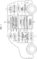
FIG. 1 is a schematic diagram illustrating the entire configuration of an engine control unit according to an embodiment of the invention; and -
FIG. 2 is a flowchart illustrating steps of a control of an engine control unit according to the embodiment of the invention. - An embodiment of the invention will now be described with reference to the drawings. The engine control unit according to the embodiment is equipped in a vehicle. Examples of the vehicle include small cars, such as passenger cars, and large cars, such as trucks and buses.
- The entire configuration of an engine control unit according to an embodiment will now be described with reference to
FIG. 1 . The engine control unit performs an idling stop and start control (hereinafter abbreviated as "ISS control"). In specific, the engine control unit performs an idling-stop to automatically stop anengine 1 if an idling-stop condition holds, and performs an idling-start (engine restart) to restart theengine 1 if a restart condition holds during the idling-stop. - The engine control unit includes an electronic control unit (ECU) 10. The
ECU 10 includes a large scale integration (LSI) device or an embedded electronic device into which a microprocessor, a read only memory (ROM), and a random access memory (RAM) are integrated. - The output of the
ECU 10 is connected todevices ECU 10 and are supplied with power from abattery 2. The input of theECU 10 is connected tosensors 6 to 9 for detecting information necessary for the ISS control and its accompanying controls. The input of theECU 10 is also connected to an ignition switch (ignition SW) 20. The engine control unit encompasses theECU 10, thedevices 1 to 5 on its output side, and thesensors 6 to 9 on its input side. - The
devices 1 to 5 on the output side of theECU 10 will now be described. - The
engine 1 is an internal combustion engine under the ISS control. Theengine 1 is provided with a starter motor (not shown) for starting (cranking) theengine 1. Thebattery 2 feeds power to the starter motor to start theengine 1. - The
battery 2 is a secondary battery to feed power to the electrical equipment of the vehicle, such as thedevices battery 2 is charged through the operations of an alternator (not shown) driven by theengine 1, and is discharged during the operations of the electrical equipment of the vehicle, such as thedevices - Because of the limited capacity of the
battery 2, its voltage may drop in response to an increase in power consumption of the equipment such as thedevices battery 2 readily drops during a stop of theengine 1, since the alternator is not driven. The voltage of thebattery 2 significantly drops upon the restart of theengine 1, since the alternator is not driven and the restart process requires a large amount of power. - A DC/
DC converter 3 is a booster to compensate for a drop in the voltage from thebattery 2. The input of the DC/DC converter 3 is connected to thebattery 2. The output of the DC/DC converter 3 is connected to a stationary-state retainer 4 and other devices 5 (described below) via power supply lines (illustrated with solid lines). - The DC/
DC converter 3 has an operating mode for boosting the voltage from thebattery 2 and outputting the boosted voltage, and a non-operating mode for outputting the voltage from thebattery 2 as it is without boosting. These modes can be switched by a change-over switch (not shown). - The stationary-
state retainer 4 is electrically operated to maintain braking force to the vehicle for keeping its stationary-state. The stationary-state retainer 4 includes abrake 4a to brake the vehicle, and amotor pump 4b to discharge hydraulic fluid to operate thebrake 4a. In the stationary-state retainer 4, discharge of the hydraulic fluid from themotor pump 4b activates thebrake 4a. In specific, in a stationary-state of the vehicle, the operatingmotor pump 4b activates thebrake 4a to keep the stationary-state of the vehicle, while thenon-operating motor pump 4b does not activate thebrake 4a to release the vehicle from the stationary-state. - The other devices 5 (illustrated with a dashed line) include, for example, a car navigation system and ECUs other than the
ECU 10. The other devices 5 may have troubles due to a drop in the applied voltage. The other devices 5 may be omitted. - The
sensors 6 to 9 on the input side of theECU 10 will now be described. - The brake switch (brake SW) 6 detects a braking operation of a driver. The information on the braking operation detected with the
brake switch 6 is transmitted to theECU 10. Thebrake switch 6 may be replaced with any other detector, such as brake-fluid pressure sensor, that detects a braking operation of the driver. In this case, the information on the brake-fluid pressure detected with the brake-fluid pressure sensor is transmitted to theECU 10. - The
speed sensor 7 detects the speed V of the vehicle. The information on the speed V detected with thespeed sensor 7 is transmitted to theECU 10. - The G-
sensor 8 detects a longitudinal acceleration αS of the vehicle, to determine a grade of a road on which the vehicle is running. The information on the longitudinal acceleration αS of the vehicle detected with the G-sensor 8 is transmitted to theECU 10. - The other sensors 9 (illustrated with a dashed line) detect other information (e.g., a driver's manipulation of an accelerator or a steering, or a charging state of the battery 2), if the
ECU 10 requires the information for the ISS control in addition to the information detected with thebrake switch 6, thespeed sensor 7, and the G-sensor 8. Theother sensors 9 may be omitted if theECU 10 requires no other information. - The
ignition switch 20 has a lock position, an accessory position, an ignition-ON position, and a start position. Theignition switch 20 is manipulated by a driver into the start position and functions as a starter switch for manually starting theengine 1. Theignition switch 20 at the ignition-ON position can activate theengine 1 and various systems in the vehicle, such as the engine control unit including theECU 10. TheECU 10, which is connected to theignition switch 20, detects a manual start of theengine 1 by the driver on the basis of manipulation signals from theignition switch 20. - Although the
ECU 10 controls a wide variety of systems related to theengine 1, the following description of theECU 10 will focus on the configurations for the ISS control. - The
ECU 10 includes several functional components, such as a road-grade acquirer 11 to acquire a road-grade θ at the location of the vehicle (hereinafter abbreviated as "road-grade"); adiagnoser 12 to diagnose (find some abnormality) the states of various devices equipped in the vehicle, in particular, components operating under an idling-stop control; an idling-stop condition determiner 14; an idling-stop controller 15; and an idling-start controller 16. - During an idling-stop to automatically stop the
engine 1 and make the vehicle into a stationary-state, theECU 10 outputs control signals for maintaining braking force to the vehicle and keeping its stationary-state, to the stationary-state retainer 4. In specific, if the speed V detected with thespeed sensor 7 indicates the stationary-state of the vehicle during an idling-stop, theECU 10 controls themotor pump 4b of the stationary-state retainer 4 to maintain the operations of thebrake 4a, thereby keeping the stationary-state of the vehicle. Upon completion of the idling-start thereafter, theECU 10 controls themotor pump 4b of the stationary-state retainer 4 to stop operating thebrake 4a, thereby releasing the vehicle from the stationary-state. - The phrase "the speed V detected with the
speed sensor 7 indicates the stationary-state of the vehicle" refers to that the speed V detected with thespeed sensor 7 is not higher than a threshold speed (i.e., 0 km/h or substantially 0 km/h) defining the stationary-state. - The
ECU 10 outputs control signals for operating the DC/DC converter 3 during the idling-stop to stop theengine 1, and outputs control signals for stopping the DC/DC converter 3 upon completion of the idling-start to restart theengine 1. That is, theECU 10 controls the DC/DC converter 3 to compensate for a voltage drop in thebattery 2 between the beginning of the stop of theengine 1 under the idling-stop control and the completion of the restart under the idling-start control. The voltage of thebattery 2 significantly drops during the idling-start, since the restart of theengine 1 requires a large amount of power. The DC/DC converter 3 also operates during the idling-start, to compensate for the drop in the voltage applied to the stationary-state retainer 4 and the other devices 5. - The road-
grade acquirer 11, thediagnoser 12, the idling-stop condition determiner 14, the idling-stop controller 15, and the idling-start controller 16 will now be described in sequence. - The road-
grade acquirer 11 acquires a road-grade θ, for example, by estimation calculation. The road-grade acquirer 11 includes several functional components, such as a stationary-state road-grade estimator 11a and a running-state road-grade estimator 11b. The road-grade acquirer 11 acquires a road-grade θS from the stationary-state road-grade estimator 11a, and a road-grade θC from the running-state road-grade estimator 11b. In the road-grade acquirer 11, the stationary-state road-grade estimator 11a estimates the road-grade θS if the speed V detected with thespeed sensor 7 indicates the stationary-state of the vehicle, and the running-state road-grade estimator 11b estimates the road-grade θC if the speed V detected with thespeed sensor 7 does not indicate the stationary-state. - The stationary-state road-
grade estimator 11a will now be described. The stationary-state road-grade θS is estimated based on the longitudinal acceleration αS detected with the G-sensor 8 without considering effects caused by the run of the vehicle. - The stationary-state road-
grade estimator 11a estimates the stationary-state road-grade θS through Expression (1):
sensor 8, and g is the gravitational acceleration. - The running-state road-
grade estimator 11b will now be described. During running of the vehicle, the longitudinal acceleration αS detected with the G-sensor 8 varies depending on the running state even at a constant road-grade. The running-state road-grade estimator 11b therefore estimates the road-grade θC through correction of the longitudinal acceleration αS detected with the G-sensor 8 on the basis of the running state of the vehicle. In specific, the road-grade θC is estimated based on Expressions (2) and (3). - The acceleration αV of the vehicle is calculated through Expression (2) for differentiating the speed V detected with the
speed sensor 7 with respect to time:
- The road-grade θC is calculated through Expression (3) below, such that the difference between the longitudinal acceleration αS detected with the G-
sensor 8 and the acceleration αV of the vehicle calculated through Expression (2) is divided by the gravitational acceleration g:
- If the
brake switch 6 detects a braking operation, the running-state road-grade estimator 11b may estimate the road-grade θC through further correction of the road-grade calculated through Expression (3) into a higher grade (steepening an uphill slope, or making a downhill slope gentler) . In a vehicle running at a certain road-grade, the front part of the vehicle under a braking operation sinks in comparison with that without a braking operation. Such inclination of the vehicle relative to the road-grade should be corrected, to improve the accuracy of estimation of the road-grade. - The running-state road-
grade estimator 11b estimates the running-state road-grade θC, on the basis of parameters corresponding to the running state of the vehicle, such as the longitudinal acceleration αS detected with the G-sensor 8, the speed V detected with thespeed sensor 7, and a braking operation detected with thebrake switch 6, as described above. - The
diagnoser 12 diagnoses devices equipped in the vehicle. Among the devices to be diagnosed by thediagnoser 12, some are diagnosed at a substantially constant accuracy regardless of the operating modes of the devices, and the others can be diagnosed at a higher accuracy in an operating mode than that in a non-operating mode. The devices include some components of the engine control unit. In this aspect, thediagnoser 12 performs a self-diagnosis of the engine control unit. - The
diagnoser 12 diagnoses the devices at any timing, for example, upon a manual start of theengine 1, during an idling-stop, and during an idling-start. For example, thediagnoser 12 diagnoses the sensors upon a manual start of theengine 1; diagnoses the devices for an idling-stop control, such as the stationary-state retainer 4, during an idling-stop; and diagnoses the devices for restart of theengine 1, such as the DC/DC converter 3 (described below), during an idling-start. - Although the
diagnoser 12 can diagnose any component operating under the idling-stop control, the following description will focus on the DC/DC converter 3 and the stationary-state retainer 4, which operate under the ISS control (i.e., during an automatic stop of theengine 1 and a restart of the engine 1) and are suitable for diagnosis during their operations. - The DC/
DC converter 3, which operates upon a voltage drop caused by the restart of theengine 1, should be diagnosed during an idling-start to restart theengine 1. The DC/DC converter 3 also operates upon a manual start of theengine 1 by a driver as well as during the idling-start when the manual start of theengine 1 readily causes a voltage drop like the idling-start. The DC/DC converter 3, however, is not diagnosed upon the manual start of theengine 1 because the diagnosis may not be performed properly due to incomplete activation of the components of the engine control unit including theECU 10 including thediagnoser 12. - The diagnosis of the DC/
DC converter 3 with thediagnoser 12 will now be described. - The
diagnoser 12 diagnoses the DC/DC converter 3 during an idling-start. The DC/DC converter 3 is diagnosed while it is significantly boosting the voltage of thebattery 2, to improve the accuracy of the diagnosis. - The
diagnoser 12 diagnoses the DC/DC converter 3, for example, through comparison of the output voltage of the DC/DC converter 3 with a voltage. In this case, the DC/DC converter 3 is diagnosed to be normal if the output voltage is higher than the voltage, and is diagnosed to be abnormal if the output voltage is not higher than the voltage. The voltage is experimentally or empirically determined in advance, for example, by adding a margin to the lowest voltage that can properly operate the electrical equipment, such as the stationary-state retainer 4 and the other devices 5, which may have troubles due to a drop in the applied voltage. - The
diagnoser 12 may diagnose the DC/DC converter 3 during an idling-stop to stop theengine 1, instead of during an idling-start. This configuration can also allow diagnosis of the DC/DC converter 3 in an operating mode other than the idling-start. The accuracy of diagnosis during the idling-stop is lower than that during the idling-start because of a smaller increment in the voltage boosted by the DC/DC converter 3. - The diagnosis of the stationary-
state retainer 4 with thediagnoser 12 will now be described. Thediagnoser 12 diagnoses the stationary-state retainer 4 between the beginning of an idling-stop to stop theengine 1 and the completion of an idling-start. The stationary-state retainer 4, which keeps the stationary-state of the vehicle during the idling-stop to stop theengine 1, is diagnosed by thediagnoser 12 within a time at which the vehicle stops. In specific, thediagnoser 12 diagnoses whether thebrake 4a and themotor pump 4b of the stationary-state retainer 4 are in a normal operating mode. - The
diagnoser 12 diagnoses the stationary-state retainer 4, for example, through comparison of the actual pressure of the hydraulic fluid for operating thebrake 4a or the hydraulic fluid discharged from themotor pump 4b with a pressure. In this case, the stationary-state retainer 4 is diagnosed to be normal if the actual pressure is higher than the pressure, and is diagnosed to be abnormal if the actual pressure is lower than the pressure. The pressure is experimentally or empirically determined in advance by adding a margin to the lowest pressure of the hydraulic fluid that can operate thebrake 4a to keep the stationary-state of the vehicle. - The stationary-
state retainer 4 may also be diagnosed through comparison of the voltage applied to thebrake 4a or themotor pump 4b with a voltage, like the diagnosis of the DC/DC converter 3. - The
ECU 10 controls thediagnoser 12 to determine satisfaction of a diagnostic condition. If an idling-stop condition (described in detail below) holds under satisfaction of the diagnostic condition, the idling-stop controller 15 performs an idling-stop. - The phrase "diagnostic condition" refers to a condition that the
diagnoser 12 finds no abnormality in the devices. The diagnostic condition holds if thediagnoser 12 diagnoses the devices to be normal, or if thediagnoser 12 has not diagnosed the devices yet. In other words, the diagnostic condition also holds when the normality of the devices is unclear. - The idling-stop condition consists of a speed condition, a road-grade condition, and the other condition. That is, satisfaction of the idling-stop condition requires satisfaction of all the speed condition, the road-grade condition, and the other condition.
- The phrase "speed condition" refers to a condition that the speed V detected with the
speed sensor 7 is lower than a speed V1. The speed V1 is experimentally or empirically determined in advance, to be the highest speed immediately before the stop of the vehicle that can be deemed to reflect a driver's intention to stop the vehicle. The speed V1 is, for example, 10 to 15 km/h. - The speed condition is satisfied if the speed V detected with the
speed sensor 7 is lower than the speed V1, that is, in both cases where the speed V indicates the stationary-state of the vehicle (the speed V is substantially 0 km/h) and where the speed V does not indicate the stationary-state. The idling-stop condition that holds for the speed V indicating the stationary-state is defined as a stationary-state idling-stop condition, while that for the speed V not indicating the stationary-state is defined as a coasting-state idling-stop condition. - The road-grade condition differs between the stationary-state and the coasting-state of the vehicle, and differs between before and after the initial idling-stop (automatic stop of the engine 1). The phrase "initial idling-stop" refers to the first automatic stop of the
engine 1 since the manual start of theengine 1 by a driver to launch the vehicle. The experience of the idling-stop is cleared through a manual stop of theengine 1 by the driver. - The road-grade conditions for the stationary-state and the coasting-state will now be described in sequence. The satisfaction of the road-grade condition is determined based on the road-grade θ acquired by the road-
grade acquirer 11. In specific, the determination is based on the road-grade θS estimated with the stationary-state road-grade estimator 11a, or the road-grade θC estimated with the running-state road-grade estimator 11b, depending on the speed of the vehicle. - The road-grade condition for the stationary-state differs between before and after the initial idling-stop.
- The road-grade condition for the stationary-state before the initial idling-stop requires the road-grade θS estimated with the stationary-state road-
grade estimator 11a to be a first stationary-state road-grade θPS1 or lower. - That is, the stationary-state idling-stop condition includes the road-grade θS estimated with the stationary-state road-
grade estimator 11a being not higher than the first stationary-state road-grade θPS1 before the initial idling-stop. - In contrast, the road-grade condition for the stationary-state after the initial idling-stop requires the road-grade θS estimated with the stationary-state road-
grade estimator 11a to be a second stationary-state road-grade θPS2 or lower. The second stationary-state road-grade θPS2 is higher than the first stationary-state road-grade θPS1. - That is, the stationary-state idling-stop condition includes the road-grade θS estimated with the stationary-state road-
grade estimator 11a being not higher than the second stationary-state road-grade θPS2 after the initial idling-stop. - The road-grade condition for the coasting-state differs between before and after the initial idling-stop.
- The road-grade condition for the coasting-state before the initial idling-stop requires the road-grade θC estimated with the running-state road-
grade estimator 11b to be a first coasting-state road-grade θPC1 or lower. The first coasting-state road-grade θPC1 is lower than the first stationary-state road-grade θPS1. - That is, the coasting-state idling-stop condition includes the road-grade θC estimated with the running-state road-
grade estimator 11b being not higher than the first coasting-state road-grade θPC1 before the initial idling-stop. - In contrast, the road-grade condition for the coasting-state after the initial idling-stop requires the road-grade θC estimated with the running-state road-
grade estimator 11b to be a second coasting-state road-grade θPC2 or lower. - That is, the coasting-state idling-stop condition includes the road-grade θC estimated with the running-state road-
grade estimator 11b being not higher than the second coasting-state road-grade θPC2 after the initial idling-stop. - The stationary-state road-grades θPS and the coasting-state road-grades θPC are experimentally or empirically determined in advance. The coasting-state road-grade θPC is gentler (i.e., has a lower value) than the stationary-state road-grade θPS. In other words, the stationary-state road-grade θPS is steeper (i.e., has a higher value) than the coasting-state road-grade θPC.
- The estimation of the running-state road-grade θC can be disturbed by changes in the running state of the vehicle, such as a variation in the speed and a braking operation, while the estimation of the stationary-state road-grade θS is not readily affected by such disturbing factors . For example, the attitude of the vehicle readily varies in the running-state, but is basically constant in the stationary-state; hence, the road-grade θ can be more accurately estimated in the stationary-state than in the running-state.
- The stationary-state road-grade θPS for determination of the stationary-state road-grade θS, which is more accurately estimated, is steeper than the coasting-state road-grade θPC for determination of the coasting-state road-grade θC. The range of the grade that satisfies the road-grade condition is wider in the stationary-state than that in the coasting-state, so that the road-grade condition more readily holds in the stationary-state than in the coasting-state.
- The first stationary-state road-grade θPS1 is 5°, while the second stationary-state road-grade θPS2 is 10°, for example. The first coasting-state road-grade θPC1 (i.e., the highest road-grade that can be deemed to be flat) is 2°, while the second coasting-state road-grade θPC2 is 4°, for example.
- The other condition will now be described.
- The phrase "other condition" refers to a condition that a driver's intention to stop the vehicle is determined under satisfaction of all the several preconditions required for an idling-stop.
- The several preconditions in the other condition include, for example, the completion of warming-up of the
engine 1, a non-operating mode or no necessity of devices driven by the engine 1 (e.g., a non-operating mode of an air conditioner using a compressor driven by theengine 1, a non-operating mode of the equipment of the vehicle powered by the alternator driven by theengine 1, and a negative pressure in the brake master back using the intake negative pressure of theengine 1 being not lower than a pressure), the activation of catalysts for purifying exhaust gas, and the normality of the sensors related to operations of theengine 1. - The phrase "driver's intention to stop the vehicle is determined" refers to detection of a manipulation of a service brake and no manipulation of the accelerator (i.e., the
engine 1 being in an idling mode). - The idling-stop condition may further include additional conditions, such as no driver's manipulation of the steering, and sufficient charging of the
battery 2 to power the starter motor (not shown) to start theengine 1. In this case, the idling-stop condition determiner 14 determines satisfaction of the additional conditions on the basis of the information detected with theother sensors 9, to determine satisfaction of the idling-stop condition. - The idling-
stop condition determiner 14 checks for the satisfaction of the idling-stop condition. - In specific, the idling-
stop condition determiner 14 determines satisfaction of the idling-stop condition if all the speed condition, the road-grade condition, and the other condition hold; and determines non-satisfaction of the idling-stop condition if none of the speed condition, the road-grade condition, and the other condition holds. - The idling-
stop controller 15 stops the idling if the idling-stop condition determiner 14 determines satisfaction of the idling-stop condition. In other words, the idling-stop controller 15 automatically stops theengine 1 if the idling-stop condition holds. - In addition, the idling-
stop controller 15 inhibits an idling-stop if thediagnoser 12 diagnoses the equipment, such as the DC/DC converter 3 and the stationary-state retainer 4, to be abnormal. In other words, the idling-stop controller 15 inhibits an idling-stop if theECU 10 determines non-satisfaction of the diagnostic condition. - The idling-
start controller 16 performs an idling-start if it determines satisfaction of a restart condition. - The phrase "restart condition" refers to a condition requiring at least either of "detection of a driver's intention to launch the vehicle" and "non-satisfaction of any of the several preconditions in the idling-stop condition." The phrase "detection of a driver's intention to launch the vehicle" refers to detection of a driver's release of the service brake. That is, satisfaction of the idling-stop condition leads to non-satisfaction of the restart condition, while satisfaction of the restart condition leads to non-satisfaction of the idling-stop condition in the embodiment.
- The idling-
start controller 16 performs an idling-start if the restart condition holds during an idling-stop. In contrast, the idling-start controller 16 does not perform an idling-start if the restart condition does not hold during the idling-stop. - The idling-
start controller 16 determines satisfaction of the restart condition through determination of a driver's braking operation to the vehicle on the basis of detection signals from thebrake switch 6, and determination of satisfaction of the several preconditions. - The restart condition regarding a driver's intention to launch the vehicle is not limited to the above-described condition, and may be a driver's manipulation of the accelerator or the steering, for example. In this case, the idling-
start controller 16 determines satisfaction of the restart condition on the basis of the information detected with theother sensors 9. - The idling-
start controller 16 performs an idling-start regardless of satisfaction of the restart condition, if thediagnoser 12 diagnoses the equipment, such as the DC/DC converter 3 and the stationary-state retainer 4, to be abnormal during an idling-stop. - The process of the control of the
ECU 10 will now be explained with reference to the flowchart ofFIG. 2 . Regarding a flag F inFIG. 2 , F=0 indicates that thediagnoser 12 finds some abnormality in the devices while F=1 indicates that thediagnoser 12 finds no abnormality in the devices. The flag F also represents whether the diagnostic condition holds, such that F=1 indicates satisfaction of the diagnostic condition while F=0 indicates non-satisfaction of the diagnostic condition. The control process is started upon a manual start of the engine 1 (ignition ON) and is repeated at a cycle. The steps in the flowchart are achieved by the individual functions allocated to the hardware of theECU 10 under the control of the software (computer program). - In Step S10, whether the flag F is 0 is determined. In other words, whether the diagnostic condition holds is determined in Step S10. If the diagnostic condition holds (F=1), the process goes to Step S20. If the diagnostic condition does not hold (F=0), the process goes to Step S100.
- In Step S20, the
diagnoser 12 diagnoses whether the devices have some abnormality. The process then goes to Step S22. - In Step S22, it is determined whether the diagnosis in Step S20 finds some abnormality in the devices. If some abnormality is found, the process goes to Step S23. If no abnormality is found, the process goes to Step S30.
- In Step S30, it is determined whether the other condition included in the idling-stop condition holds. If the other condition holds, the process goes to Step S31. If not, the current cycle of the control process is terminated.
- In Step S31, it is determined whether the speed V is lower than the speed V1. In other words, it is determined whether the speed V decreases below the speed V1 in Step S31. If the speed V is lower than the speed V1, the process goes to Step S32. If not, the current cycle of the control process is terminated.
- In Step S32, it is determined whether the speed V indicates the stationary-state of the vehicle (i.e., the speed V is substantially zero). If the speed V indicates the stationary-state, the process goes to Step S33. If the speed V does not indicate the stationary-state (i.e., indicates the coasting-state), the process goes to Step S36.
- In Step S33, it is determined whether the current state is before the initial idling-stop (initial IS). If the current state is before the initial idling-stop, the process goes to Step S34. If the current state is after the initial idling-stop, the process goes to Step S35.
- In Step S34, it is determined whether the road-grade θS estimated with the stationary-state road-
grade estimator 11a is the first stationary-state road-grade θPS1 or lower. If the road-grade θS is the first stationary-state road-grade θPS1 or lower, the process goes to Step S40. If not, the current cycle of the control process is terminated. - In Step S35, it is determined whether the road-grade θS estimated with the stationary-state road-
grade estimator 11a is the second stationary-state road-grade θPS2 or lower, like Step S34. If the road-grade θS is the second stationary-state road-grade θPS2 or lower, the process goes to Step S40. If not, the current cycle of the control process is terminated. - In Step S36, it is determined whether the current state is before the initial idling-stop (initial IS), like Step S33. If the current state is before the initial idling-stop, the process goes to Step S37. If the current state is after the initial idling-stop, the process goes to Step S38.
- In Step S37, it is determined whether the road-grade θC estimated with the running-state road-
grade estimator 11b is the first coasting-state road-grade θPC1 or lower. If the road-grade θC is the first coasting-state road-grade θPC1 or lower, the process goes to Step S40. If not, the current cycle of the control process is terminated. - In Step S38, it is determined whether the road-grade θC estimated with the running-state road-
grade estimator 11b is the second coasting-state road-grade θPC2 or lower, like Step S37. If the road-grade θC is the second coasting-state road-grade θPC2 or lower, the process goes to Step S40. If not, the current cycle of the control process is terminated. - Steps S30 to S38 determine the satisfaction of the idling-stop condition. In specific, Step S30 is dedicated for the determination of satisfaction of the other condition included in the idling-stop condition, Steps S31 and S32 for the speed condition, and Steps S33 to S38 for the road-grade condition.
- In Step S40, an order for an idling-stop is provided, to stop the idling. The process then goes to Step S50.
- In Step S50, the
diagnoser 12 determines whether the devices have some abnormality, like Step S20. In Step S52, it is determined whether the diagnosis in Step S50 finds some abnormality in the devices, like Step S22. Steps S50 and S52 may also involve the diagnosis peculiar to the idling-stop. If some abnormality is found, the process goes to Step S82. If no abnormality is found, the process goes to Step S60. - In Step S60, whether the restart condition holds is determined. If the restart condition holds, the process goes to Step S70. If not, the current cycle of the control process is terminated.
- In Step S70, an order for an idling-start is provided, to perform the idling-start. The process then goes to Step S80.
- In Step S80, the
diagnoser 12 diagnoses whether the devices have some abnormality, like Steps S20 and S50. In Step S81, it is determined whether the diagnosis in Step S80 finds some abnormality in the devices, like Steps S22 and S52. If some abnormality is found, the process goes to Step S82. If no abnormality is found, the current cycle of the control process is terminated. - In Step S82, the flag F is set to be 0. The current cycle of the control process is then terminated.
- In Step S23, the flag F is set to be 0. The process then goes to Step S100.
- In Step S100, an idling-stop is inhibited. For example, an idling-start is performed during an idling-stop. The current cycle of the control process is then terminated.
- The engine control unit according to the embodiment, which has the configurations described above, shows the following advantageous effects.
- In the engine control unit according to the embodiment, the coasting-state idling-stop condition includes the road-grade θC estimated with the running-state road-
grade estimator 11b being not higher than the first coasting-state road-grade θPC1 (i.e., the highest road-grade that can be deemed to be flat), before an initial idling-stop by the idling-stop controller 15. That is, the initial idling-stop in a coasting-state of the vehicle is performed at a road-grade θC estimated to be not higher than the first coasting-state road-grade θPC1. This configuration can readily avoid the unexpected behaviors of the vehicle during an idling-stop even if the normality of the devices in the engine control unit is unclear or even if the devices have some abnormality. - The coasting-state idling-stop condition includes the road-grade θC estimated with the running-state road-
grade estimator 11b being not higher than the second coasting-state road-grade θPC2 higher than the first coasting-state road-grade θPC1, after the initial idling-stop. That is, the idling can be stopped in a coasting-state of the vehicle at a road-grade not higher than the second coasting-state road-grade θPC2 higher than the first coasting-state road-grade θPC1, after the initial idling-stop. In other words, idling-stops are available in the coasting-state at not only flat roads but also slopes having the second coasting-state road-grade θPC2 or lower, after the initial idling-stop. This configuration can increase the frequency of idling-stops in the coasting-state, to improve the fuel efficiency. - These configurations can achieve the compatibility between easy avoidance of the unexpected behavior of the vehicle during an idling-stop and the improved fuel efficiency due to the increased frequency of idling-stops.
- After the initial idling stop, the devices in the engine control unit are more likely to be normal, for example. In this case, the stationary-state idling-stop condition includes the road-grade θS being not higher than the second stationary-state road-grade θPS2 higher than the first stationary-state road-grade θPS1. This configuration can increase the frequency of idling-stops in a stationary-state of the vehicle to improve the fuel efficiency without unexpected behaviors of the vehicle.
- The stationary-state idling-stop condition includes the road-grade θS being not higher than the first stationary-state road-grade θPS1 lower than the second stationary-state road-grade θPS2, before the initial idling-stop. That is, the initial idling-stop in a stationary-state of the vehicle is performed at a flat road or a gentle slope of not higher than the first stationary-state road-grade θPS1. This configuration can readily avoid the unexpected behaviors of the vehicle even if the normality of the devices equipped in the vehicle is unclear or even if the devices have some abnormality.
- The stationary-state idling-stop condition includes the road-grade being not higher than the first stationary-state road-grade θPS1 higher than the first coasting-state road-grade θPC1, before the initial idling-stop. That is, the initial idling-stop is more likely to be performed in a stationary-state of the vehicle than in a coasting-state. This configuration can more readily avoid the unexpected behaviors of the running vehicle.
- The road-
grade acquirer 11 includes the stationary-state road-grade estimator 11a for estimation of a stationary-state road-grade θS, and the running-state road-grade estimator 11b for estimation of a running-state road-grade θC. This configuration allows appropriate estimation of a road-grade θ for each of the running and stationary states of the vehicle. - In specific, the stationary-state road-
grade estimator 11a estimates a stationary-state road-grade θS, on the basis of the longitudinal acceleration αS detected with the G-sensor 8. The running-state road-grade estimator 11b estimates a road-grade θC, on the basis of not only the longitudinal acceleration αS but also parameters corresponding to the running state of the vehicle, such as the speed V detected with thespeed sensor 7 and a braking operation detected with thebrake switch 6, to compensate for the disturbance to the estimation of the road-grade. This configuration can ensure sufficient accuracy of estimation of the running-state road-grade θC. The accurate running-state road-grade θC can be used for the condition to start an idling-stop, thereby leading to the compatibility between avoidance of the unexpected behaviors of the vehicle and the improved fuel efficiency. - The idling-
start controller 16 forces theengine 1 to restart if thediagnoser 12 finds some abnormality in the devices during an idling-stop, to prevent theengine 1 from remaining stopped in spite of the abnormality in the devices. This configuration can avoid troubles due to some abnormality in the devices. - The idling-
stop controller 15 inhibits an idling-stop if thediagnoser 12 finds some abnormality in the devices, to prevent theengine 1 from being stopped in spite of the abnormality in the devices. This configuration can avoid troubles due to some abnormality in the devices. - The
diagnoser 12 diagnoses the normality of the devices, which operate during an automatic stop of theengine 1 or a restart of theengine 1, during an automatic stop of theengine 1 or a restart of theengine 1. Thediagnoser 12 can therefore certainly diagnose the devices, such as the DC/DC converter 3 and the stationary-state retainer 4, which operate during the automatic stop of theengine 1 or the restart of theengine 1. Thediagnoser 12 can diagnose the devices suitable for diagnosis during their operations, to improve the accuracy of diagnosis. - The
diagnoser 12 diagnoses the normality of the engine control unit during an idling-stop to automatically stop theengine 1. Thediagnoser 12 can therefore properly diagnose the devices operating during the stop of theengine 1. - In specific, the
diagnoser 12 diagnoses the stationary-state retainer 4 for keeping the stationary-state of the vehicle during an idling-stop to stop theengine 1, and the DC/DC converter 3 for feeding power to the electrical equipment such as the stationary-state retainer 4. Idling-stops and idling-starts are performed at flat roads or substantially flat roads, if any of the DC/DC converter 3 and the stationary-state retainer 4 is not diagnosed to be normal or is diagnosed to be abnormal during the stop of theengine 1. This configuration can avoid or prevent the unexpected behaviors of the vehicle regardless of some abnormality (failure) in the DC/DC converter 3 or the stationary-state retainer 4. Idling-stops in coasting and stationary states of the vehicle are available even in such a case, to achieve the compatibility between avoidance of the unexpected behaviors of the vehicle and the improved fuel efficiency. - The invention is not limited to the above-described embodiment and may be modified without departing from its gist. The individual features of the embodiment and its modifications may be selectively employed as necessary or properly combined with one another.
- In the embodiment, the
ECU 10 stops the idling if both the diagnostic condition and the idling-stop condition are satisfied. Alternatively, theECU 10 may stop the idling if only the idling-stop condition is satisfied. In this case, thediagnoser 12 may be omitted from theECU 10, to reduce the control loads for the idling-stop. - In the embodiment, the running-state road-
grade estimator 11b estimates a road-grade θC through correction of the longitudinal acceleration αS detected with the G-sensor 8 on the basis of the running state of the vehicle. Alternatively, the running-state road-grade θC may be acquired by multiplying "sinθS (where θS is the stationary-state road-grade)" by " (αS-αV)/αS." In other words, the running-state road-grade estimator 11b may estimate the road-grade θC through correction of the road-grade θS estimated with the stationary-state road-grade estimator 11a on the basis of the running state of the vehicle. This configuration can also ensure sufficient accuracy of estimation of both the stationary-state road-grade θS and the running-state road-grade θC. The accurate running-state road-grade θC can be used for the condition to start an idling-stop, which leads to the compatibility between avoidance of the unexpected behaviors of the vehicle and the improved fuel efficiency. - In the embodiment, the running-state road-
grade estimator 11b estimates a running-state road-grade on the basis of parameters corresponding to the running state of the vehicle. Alternatively, the running-state road-grade may be estimated on the basis of an image of the road on which the vehicle is running, or may be acquired via a wide area network, for example. - In the embodiment, the stationary-state road-grade θPS for the determination of satisfaction of the road-grade condition is steeper (i.e., has a higher value) than the coasting-state road-grade θPC for the same determination. Alternatively, the stationary-state road-grade θPS may be identical to the coasting-state road-grade θPC, provided that the accuracy of the estimated running-state road-grade θC is sufficient. This configuration can ensure the opportunity for idling-stops in a coasting-state of the vehicle before diagnosis of the normality of the devices.
- The road-
grade acquirer 11 of theECU 10 may acquire a coasting-state road-grade through the same estimation calculation as that for the stationary-state. Alternatively, theECU 10 may further include a road-grade sensor to detect a coasting-state road-grade that can be used as it is. These configurations can reduce the calculation loads on theECU 10. The configurations also allow the sensors required for the estimation calculation of the running-state road-grade θC to be omitted, thereby simplifying the structure. - In the embodiment, the
diagnoser 12 diagnoses the devices at any timing. Alternatively, thediagnoser 12 may diagnose the devices only during the initial idling-stop. This configuration can reduce the number of diagnosis with thediagnoser 12, thereby reducing the control loads on theECU 10. - Reference signs used in the description are listed as below:
- 1
- engine,
- 2
- battery,
- 3
- DC/DC converter,
- 4
- stationary-state retainer,
- 4a
- brake,
- 4b
- motor pump,
- 5
- other devices,
- 6
- brake switch,
- 7
- speed sensor,
- 8
- G-sensor,
- 9
- other sensors,
- 10
- ECU,
- 11
- road-grade acquirer,
- 11a
- stationary-state road-grade estimator,
- 11b
- running-state road-grade estimator,
- 12
- diagnoser,
- 14
- idling-stop condition determiner,
- 15
- idling-stop controller,
- 16
- idling-start controller,
- 20
- ignition switch,
- θPC1
- first coasting-state road-grade,
- θPC2
- second coasting-state road-grade,
- θPS1
- first stationary-state road-grade, and
- θPS2
- second stationary-state road-grade.
- The invention thus described, it will be obvious that the same may be varied in many ways without departing from the scope of the invention, as defined by the appended claims.
Claims (3)
- An engine control unit comprising:an idling-stop controller (15) to automatically stop an engine (1) equipped in a vehicle if a coasting-state idling-stop condition or a stationary-state idling-stop condition is satisfied, the coasting-state idling-stop condition including a coasting-state of the vehicle at a speed (V1) or lower, the stationary-state idling-stop condition including a stationary-state of the vehicle;an idling-start controller (16) to restart the engine (1) if a restart condition is satisfied during an automatic stop of the engine (1) by the idling-stop controller (15);a diagnoser (12) to find, during the automatic stop of the engine (1) or a restart of the engine (1), some abnormality in devices operating during an automatic stop of the engine (1) or the restart of the engine (1); anda road-grade acquirer (11) to acquire a road-grade (θ) at the location of the vehicle, characterized in thatthe coasting-state idling-stop condition includes the road-grade (θ) acquired by the road-grade acquirer (11) being not higher than a first coasting-state road-grade (θPC1) before an initial automatic stop of the engine (1) by the idling-stop controller (15),the coasting-state idling-stop condition includes the road-grade (θ) acquired by the road-grade acquirer (11) being not higher than a second coasting-state road-grade (θPC2) higher than the first coasting-state road-grade (θPC1), after the initial automatic stop of the engine (1) by the idling-stop controller (15),the stationary-state idling-stop condition includes the road-grade (θ) acquired by the road-grade acquirer (11) being not higher than a first stationary-state road-grade (θPS1) higher than the first coasting-state road-grade (θPC1), before the initial automatic stop of the engine (1) by the idling-stop controller (15),the stationary-state idling-stop condition includes the road-grade (θ) acquired by the road-grade acquirer (11) being not higher than a second stationary-state road-grade (θPS2) higher than the first stationary-state road-grade (θPS1), after the initial automatic stop of the engine (1) by the idling-stop controller (15),the road-grade acquirer (11) acquires a road-grade (θ) estimated based on a longitudinal acceleration (αS) of the vehicle in a stationary-state, and acquires a road-grade (θ) estimated based on the longitudinal acceleration (αS) of the vehicle and another acceleration (αV) of the vehicle in a running-state, andthe idling-stop controller (15) inhibits an automatic stop of the engine (1) if the diagnoser (12) finds some abnormality in the devices operating during an automatic stop of the engine (1) or a restart of the engine (1).
- The engine control unit according to claim 1, wherein the idling-start controller (16) restarts the engine (1) if the diagnoser (12) finds some abnormality in the devices operating during an automatic stop of the engine (1) or a restart of the engine (1), during the automatic stop of the engine (1).
- The engine control unit according to claim 1 or 2, wherein the devices operating during an automatic stop the engine (1) or a restart of the engine (1) include a stationary-state retainer (4) to maintain braking force to the vehicle for keeping the stationary-state of the vehicle, during an automatic stop of the engine (1) of the vehicle in the stationary-state.
Applications Claiming Priority (1)
| Application Number | Priority Date | Filing Date | Title |
|---|---|---|---|
| JP2013115860A JP5742883B2 (en) | 2013-05-31 | 2013-05-31 | Engine control device |
Publications (3)
| Publication Number | Publication Date |
|---|---|
| EP2808536A2 EP2808536A2 (en) | 2014-12-03 |
| EP2808536A3 EP2808536A3 (en) | 2015-11-25 |
| EP2808536B1 true EP2808536B1 (en) | 2019-12-11 |
Family
ID=50932962
Family Applications (1)
| Application Number | Title | Priority Date | Filing Date |
|---|---|---|---|
| EP14170129.2A Active EP2808536B1 (en) | 2013-05-31 | 2014-05-27 | Engine control unit |
Country Status (3)
| Country | Link |
|---|---|
| EP (1) | EP2808536B1 (en) |
| JP (1) | JP5742883B2 (en) |
| CN (1) | CN104213992B (en) |
Families Citing this family (6)
| Publication number | Priority date | Publication date | Assignee | Title |
|---|---|---|---|---|
| CN105649792B (en) * | 2016-01-08 | 2018-07-03 | 潍柴动力股份有限公司 | A kind of heavy vehicle engine upward slope auxiliary torque lifting means and method for improving |
| JP6655442B2 (en) * | 2016-03-25 | 2020-02-26 | 日立オートモティブシステムズ株式会社 | Vehicle control device |
| JP6642459B2 (en) * | 2017-01-13 | 2020-02-05 | トヨタ自動車株式会社 | Vehicle control device |
| CN109407714A (en) * | 2017-12-15 | 2019-03-01 | 重庆长安汽车股份有限公司 | Gradient initiative recognition and vehicle speed control system and method |
| CN109139276B (en) * | 2018-09-30 | 2020-10-27 | 安徽江淮汽车集团股份有限公司 | Automobile start-stop control method |
| CN114857254A (en) * | 2022-05-11 | 2022-08-05 | 潍柴动力股份有限公司 | Control method for neutral coasting of vehicle, automatic transmission and vehicle |
Family Cites Families (7)
| Publication number | Priority date | Publication date | Assignee | Title |
|---|---|---|---|---|
| JP5257389B2 (en) | 2010-03-22 | 2013-08-07 | 株式会社デンソー | Abnormality diagnosis device for idle stop system |
| WO2012011568A1 (en) * | 2010-07-23 | 2012-01-26 | 日産自動車株式会社 | Engine automatic stop device and automatic stop method |
| US8594912B2 (en) * | 2011-04-28 | 2013-11-26 | GM Global Technology Operations LLC | Stop/start control systems and methods for internal combustion engines |
| JP5585787B2 (en) * | 2011-06-09 | 2014-09-10 | 三菱自動車工業株式会社 | Vehicle control device |
| JP5682758B2 (en) * | 2011-06-09 | 2015-03-11 | 三菱自動車工業株式会社 | Idle stop vehicle |
| JP5019083B1 (en) * | 2011-06-09 | 2012-09-05 | 三菱自動車工業株式会社 | Vehicle control device |
| JP6205688B2 (en) * | 2011-09-16 | 2017-10-04 | 三菱自動車工業株式会社 | Vehicle control device |
-
2013
- 2013-05-31 JP JP2013115860A patent/JP5742883B2/en active Active
-
2014
- 2014-05-27 EP EP14170129.2A patent/EP2808536B1/en active Active
- 2014-05-30 CN CN201410240543.0A patent/CN104213992B/en active Active
Non-Patent Citations (1)
| Title |
|---|
| None * |
Also Published As
| Publication number | Publication date |
|---|---|
| CN104213992A (en) | 2014-12-17 |
| CN104213992B (en) | 2017-04-26 |
| EP2808536A2 (en) | 2014-12-03 |
| JP5742883B2 (en) | 2015-07-01 |
| EP2808536A3 (en) | 2015-11-25 |
| JP2014234748A (en) | 2014-12-15 |
Similar Documents
| Publication | Publication Date | Title |
|---|---|---|
| EP2808536B1 (en) | Engine control unit | |
| US8880318B2 (en) | Vehicle controlling system | |
| CN102418611B (en) | Engine control apparatus | |
| US7869911B2 (en) | Vehicle control unit and vehicle control method | |
| US9714621B2 (en) | Automatic engine control apparatus | |
| CN1636806B (en) | Brake system for idle stop vehicle | |
| JP2009528213A (en) | Device that activates and deactivates the vehicle engine according to traffic conditions | |
| JP2002070605A (en) | Automatic stopping/starting controller for engine | |
| US20160368497A1 (en) | Vehicle speed control apparatus | |
| US20160186674A1 (en) | Electronic controller | |
| US20140345564A1 (en) | Idling stop control device, vehicle and vehicle control method | |
| US9267447B2 (en) | Engine restart control apparatus, vehicle and vehicle control method | |
| US11789085B2 (en) | Battery diagnosis device, battery diagnosis method, non-transitory storage medium, and vehicle | |
| EP2787202A1 (en) | Engine control unit | |
| JP2011247237A (en) | Device for control of idling stop vehicle | |
| JP2012111412A (en) | Vehicle control system | |
| EP2781436A1 (en) | Power steering device of vehicle | |
| JP2010248917A (en) | Control device and control method | |
| CN111032462B (en) | Vehicle control device | |
| CN106150711B (en) | Method and system for controlling fuel pump of hybrid diesel vehicle | |
| WO2015128728A1 (en) | Start-stop system for an internal combustion engine with a change of steering angle as automatic start condition | |
| JP2010052573A (en) | Control device of idling stop vehicle | |
| JP7166716B2 (en) | vehicle controller | |
| US20190256080A1 (en) | Method for the Situation-Based Adaptation of the Charging Strategy of Energy Stores of a Vehicle | |
| JP2005090302A (en) | Idling stop device |
Legal Events
| Date | Code | Title | Description |
|---|---|---|---|
| PUAI | Public reference made under article 153(3) epc to a published international application that has entered the european phase |
Free format text: ORIGINAL CODE: 0009012 |
|
| 17P | Request for examination filed |
Effective date: 20140527 |
|
| AK | Designated contracting states |
Kind code of ref document: A2 Designated state(s): AL AT BE BG CH CY CZ DE DK EE ES FI FR GB GR HR HU IE IS IT LI LT LU LV MC MK MT NL NO PL PT RO RS SE SI SK SM TR |
|
| AX | Request for extension of the european patent |
Extension state: BA ME |
|
| R17P | Request for examination filed (corrected) |
Effective date: 20150417 |
|
| PUAL | Search report despatched |
Free format text: ORIGINAL CODE: 0009013 |
|
| AK | Designated contracting states |
Kind code of ref document: A3 Designated state(s): AL AT BE BG CH CY CZ DE DK EE ES FI FR GB GR HR HU IE IS IT LI LT LU LV MC MK MT NL NO PL PT RO RS SE SI SK SM TR |
|
| AX | Request for extension of the european patent |
Extension state: BA ME |
|
| RIC1 | Information provided on ipc code assigned before grant |
Ipc: F02N 11/08 20060101AFI20151021BHEP Ipc: F02N 11/10 20060101ALI20151021BHEP |
|
| RBV | Designated contracting states (corrected) |
Designated state(s): AL AT BE BG CH CY CZ DE DK EE ES FI FR GB GR HR HU IE IS IT LI LT LU LV MC MK MT NL NO PL PT RO RS SE SI SK SM TR |
|
| STAA | Information on the status of an ep patent application or granted ep patent |
Free format text: STATUS: EXAMINATION IS IN PROGRESS |
|
| 17Q | First examination report despatched |
Effective date: 20180716 |
|
| RAP1 | Party data changed (applicant data changed or rights of an application transferred) |
Owner name: MITSUBISHI JIDOSHA KOGYO KABUSHIKI KAISHA |
|
| GRAP | Despatch of communication of intention to grant a patent |
Free format text: ORIGINAL CODE: EPIDOSNIGR1 |
|
| STAA | Information on the status of an ep patent application or granted ep patent |
Free format text: STATUS: GRANT OF PATENT IS INTENDED |
|
| INTG | Intention to grant announced |
Effective date: 20190717 |
|
| GRAS | Grant fee paid |
Free format text: ORIGINAL CODE: EPIDOSNIGR3 |
|
| GRAA | (expected) grant |
Free format text: ORIGINAL CODE: 0009210 |
|
| STAA | Information on the status of an ep patent application or granted ep patent |
Free format text: STATUS: THE PATENT HAS BEEN GRANTED |
|
| AK | Designated contracting states |
Kind code of ref document: B1 Designated state(s): AL AT BE BG CH CY CZ DE DK EE ES FI FR GB GR HR HU IE IS IT LI LT LU LV MC MK MT NL NO PL PT RO RS SE SI SK SM TR |
|
| REG | Reference to a national code |
Ref country code: GB Ref legal event code: FG4D |
|
| REG | Reference to a national code |
Ref country code: CH Ref legal event code: EP |
|
| REG | Reference to a national code |
Ref country code: AT Ref legal event code: REF Ref document number: 1212442 Country of ref document: AT Kind code of ref document: T Effective date: 20191215 |
|
| REG | Reference to a national code |
Ref country code: IE Ref legal event code: FG4D |
|
| REG | Reference to a national code |
Ref country code: DE Ref legal event code: R096 Ref document number: 602014058141 Country of ref document: DE |
|
| REG | Reference to a national code |
Ref country code: NL Ref legal event code: MP Effective date: 20191211 |
|
| REG | Reference to a national code |
Ref country code: LT Ref legal event code: MG4D |
|
| PG25 | Lapsed in a contracting state [announced via postgrant information from national office to epo] |
Ref country code: GR Free format text: LAPSE BECAUSE OF FAILURE TO SUBMIT A TRANSLATION OF THE DESCRIPTION OR TO PAY THE FEE WITHIN THE PRESCRIBED TIME-LIMIT Effective date: 20200312 Ref country code: NO Free format text: LAPSE BECAUSE OF FAILURE TO SUBMIT A TRANSLATION OF THE DESCRIPTION OR TO PAY THE FEE WITHIN THE PRESCRIBED TIME-LIMIT Effective date: 20200311 Ref country code: LT Free format text: LAPSE BECAUSE OF FAILURE TO SUBMIT A TRANSLATION OF THE DESCRIPTION OR TO PAY THE FEE WITHIN THE PRESCRIBED TIME-LIMIT Effective date: 20191211 Ref country code: ES Free format text: LAPSE BECAUSE OF FAILURE TO SUBMIT A TRANSLATION OF THE DESCRIPTION OR TO PAY THE FEE WITHIN THE PRESCRIBED TIME-LIMIT Effective date: 20191211 Ref country code: LV Free format text: LAPSE BECAUSE OF FAILURE TO SUBMIT A TRANSLATION OF THE DESCRIPTION OR TO PAY THE FEE WITHIN THE PRESCRIBED TIME-LIMIT Effective date: 20191211 Ref country code: SE Free format text: LAPSE BECAUSE OF FAILURE TO SUBMIT A TRANSLATION OF THE DESCRIPTION OR TO PAY THE FEE WITHIN THE PRESCRIBED TIME-LIMIT Effective date: 20191211 Ref country code: FI Free format text: LAPSE BECAUSE OF FAILURE TO SUBMIT A TRANSLATION OF THE DESCRIPTION OR TO PAY THE FEE WITHIN THE PRESCRIBED TIME-LIMIT Effective date: 20191211 Ref country code: BG Free format text: LAPSE BECAUSE OF FAILURE TO SUBMIT A TRANSLATION OF THE DESCRIPTION OR TO PAY THE FEE WITHIN THE PRESCRIBED TIME-LIMIT Effective date: 20200311 |
|
| PG25 | Lapsed in a contracting state [announced via postgrant information from national office to epo] |
Ref country code: RS Free format text: LAPSE BECAUSE OF FAILURE TO SUBMIT A TRANSLATION OF THE DESCRIPTION OR TO PAY THE FEE WITHIN THE PRESCRIBED TIME-LIMIT Effective date: 20191211 Ref country code: HR Free format text: LAPSE BECAUSE OF FAILURE TO SUBMIT A TRANSLATION OF THE DESCRIPTION OR TO PAY THE FEE WITHIN THE PRESCRIBED TIME-LIMIT Effective date: 20191211 |
|
| PG25 | Lapsed in a contracting state [announced via postgrant information from national office to epo] |
Ref country code: AL Free format text: LAPSE BECAUSE OF FAILURE TO SUBMIT A TRANSLATION OF THE DESCRIPTION OR TO PAY THE FEE WITHIN THE PRESCRIBED TIME-LIMIT Effective date: 20191211 |
|
| PG25 | Lapsed in a contracting state [announced via postgrant information from national office to epo] |
Ref country code: NL Free format text: LAPSE BECAUSE OF FAILURE TO SUBMIT A TRANSLATION OF THE DESCRIPTION OR TO PAY THE FEE WITHIN THE PRESCRIBED TIME-LIMIT Effective date: 20191211 Ref country code: PT Free format text: LAPSE BECAUSE OF FAILURE TO SUBMIT A TRANSLATION OF THE DESCRIPTION OR TO PAY THE FEE WITHIN THE PRESCRIBED TIME-LIMIT Effective date: 20200506 Ref country code: RO Free format text: LAPSE BECAUSE OF FAILURE TO SUBMIT A TRANSLATION OF THE DESCRIPTION OR TO PAY THE FEE WITHIN THE PRESCRIBED TIME-LIMIT Effective date: 20191211 Ref country code: CZ Free format text: LAPSE BECAUSE OF FAILURE TO SUBMIT A TRANSLATION OF THE DESCRIPTION OR TO PAY THE FEE WITHIN THE PRESCRIBED TIME-LIMIT Effective date: 20191211 Ref country code: EE Free format text: LAPSE BECAUSE OF FAILURE TO SUBMIT A TRANSLATION OF THE DESCRIPTION OR TO PAY THE FEE WITHIN THE PRESCRIBED TIME-LIMIT Effective date: 20191211 |
|
| PG25 | Lapsed in a contracting state [announced via postgrant information from national office to epo] |
Ref country code: SK Free format text: LAPSE BECAUSE OF FAILURE TO SUBMIT A TRANSLATION OF THE DESCRIPTION OR TO PAY THE FEE WITHIN THE PRESCRIBED TIME-LIMIT Effective date: 20191211 Ref country code: IS Free format text: LAPSE BECAUSE OF FAILURE TO SUBMIT A TRANSLATION OF THE DESCRIPTION OR TO PAY THE FEE WITHIN THE PRESCRIBED TIME-LIMIT Effective date: 20200411 Ref country code: SM Free format text: LAPSE BECAUSE OF FAILURE TO SUBMIT A TRANSLATION OF THE DESCRIPTION OR TO PAY THE FEE WITHIN THE PRESCRIBED TIME-LIMIT Effective date: 20191211 |
|
| REG | Reference to a national code |
Ref country code: DE Ref legal event code: R097 Ref document number: 602014058141 Country of ref document: DE |
|
| REG | Reference to a national code |
Ref country code: AT Ref legal event code: MK05 Ref document number: 1212442 Country of ref document: AT Kind code of ref document: T Effective date: 20191211 |
|
| PLBE | No opposition filed within time limit |
Free format text: ORIGINAL CODE: 0009261 |
|
| STAA | Information on the status of an ep patent application or granted ep patent |
Free format text: STATUS: NO OPPOSITION FILED WITHIN TIME LIMIT |
|
| PG25 | Lapsed in a contracting state [announced via postgrant information from national office to epo] |
Ref country code: DK Free format text: LAPSE BECAUSE OF FAILURE TO SUBMIT A TRANSLATION OF THE DESCRIPTION OR TO PAY THE FEE WITHIN THE PRESCRIBED TIME-LIMIT Effective date: 20191211 |
|
| 26N | No opposition filed |
Effective date: 20200914 |
|
| PG25 | Lapsed in a contracting state [announced via postgrant information from national office to epo] |
Ref country code: PL Free format text: LAPSE BECAUSE OF FAILURE TO SUBMIT A TRANSLATION OF THE DESCRIPTION OR TO PAY THE FEE WITHIN THE PRESCRIBED TIME-LIMIT Effective date: 20191211 Ref country code: SI Free format text: LAPSE BECAUSE OF FAILURE TO SUBMIT A TRANSLATION OF THE DESCRIPTION OR TO PAY THE FEE WITHIN THE PRESCRIBED TIME-LIMIT Effective date: 20191211 Ref country code: AT Free format text: LAPSE BECAUSE OF FAILURE TO SUBMIT A TRANSLATION OF THE DESCRIPTION OR TO PAY THE FEE WITHIN THE PRESCRIBED TIME-LIMIT Effective date: 20191211 |
|
| PG25 | Lapsed in a contracting state [announced via postgrant information from national office to epo] |
Ref country code: MC Free format text: LAPSE BECAUSE OF FAILURE TO SUBMIT A TRANSLATION OF THE DESCRIPTION OR TO PAY THE FEE WITHIN THE PRESCRIBED TIME-LIMIT Effective date: 20191211 Ref country code: CH Free format text: LAPSE BECAUSE OF NON-PAYMENT OF DUE FEES Effective date: 20200531 Ref country code: IT Free format text: LAPSE BECAUSE OF FAILURE TO SUBMIT A TRANSLATION OF THE DESCRIPTION OR TO PAY THE FEE WITHIN THE PRESCRIBED TIME-LIMIT Effective date: 20191211 Ref country code: LI Free format text: LAPSE BECAUSE OF NON-PAYMENT OF DUE FEES Effective date: 20200531 |
|
| REG | Reference to a national code |
Ref country code: BE Ref legal event code: MM Effective date: 20200531 |
|
| GBPC | Gb: european patent ceased through non-payment of renewal fee |
Effective date: 20200527 |
|
| PG25 | Lapsed in a contracting state [announced via postgrant information from national office to epo] |
Ref country code: LU Free format text: LAPSE BECAUSE OF NON-PAYMENT OF DUE FEES Effective date: 20200527 |
|
| PG25 | Lapsed in a contracting state [announced via postgrant information from national office to epo] |
Ref country code: IE Free format text: LAPSE BECAUSE OF NON-PAYMENT OF DUE FEES Effective date: 20200527 Ref country code: GB Free format text: LAPSE BECAUSE OF NON-PAYMENT OF DUE FEES Effective date: 20200527 |
|
| PG25 | Lapsed in a contracting state [announced via postgrant information from national office to epo] |
Ref country code: BE Free format text: LAPSE BECAUSE OF NON-PAYMENT OF DUE FEES Effective date: 20200531 |
|
| PG25 | Lapsed in a contracting state [announced via postgrant information from national office to epo] |
Ref country code: TR Free format text: LAPSE BECAUSE OF FAILURE TO SUBMIT A TRANSLATION OF THE DESCRIPTION OR TO PAY THE FEE WITHIN THE PRESCRIBED TIME-LIMIT Effective date: 20191211 Ref country code: MT Free format text: LAPSE BECAUSE OF FAILURE TO SUBMIT A TRANSLATION OF THE DESCRIPTION OR TO PAY THE FEE WITHIN THE PRESCRIBED TIME-LIMIT Effective date: 20191211 Ref country code: CY Free format text: LAPSE BECAUSE OF FAILURE TO SUBMIT A TRANSLATION OF THE DESCRIPTION OR TO PAY THE FEE WITHIN THE PRESCRIBED TIME-LIMIT Effective date: 20191211 |
|
| PG25 | Lapsed in a contracting state [announced via postgrant information from national office to epo] |
Ref country code: MK Free format text: LAPSE BECAUSE OF FAILURE TO SUBMIT A TRANSLATION OF THE DESCRIPTION OR TO PAY THE FEE WITHIN THE PRESCRIBED TIME-LIMIT Effective date: 20191211 |
|
| REG | Reference to a national code |
Ref country code: FR Ref legal event code: PLFP Year of fee payment: 10 |
|
| PGFP | Annual fee paid to national office [announced via postgrant information from national office to epo] |
Ref country code: FR Payment date: 20230411 Year of fee payment: 10 Ref country code: DE Payment date: 20230404 Year of fee payment: 10 |