EP2808489A1 - Sicherungsplatte - Google Patents
Sicherungsplatte Download PDFInfo
- Publication number
- EP2808489A1 EP2808489A1 EP14161664.9A EP14161664A EP2808489A1 EP 2808489 A1 EP2808489 A1 EP 2808489A1 EP 14161664 A EP14161664 A EP 14161664A EP 2808489 A1 EP2808489 A1 EP 2808489A1
- Authority
- EP
- European Patent Office
- Prior art keywords
- projection
- lock plate
- component
- planar portion
- assembly
- Prior art date
- Legal status (The legal status is an assumption and is not a legal conclusion. Google has not performed a legal analysis and makes no representation as to the accuracy of the status listed.)
- Granted
Links
- 238000000034 method Methods 0.000 claims abstract description 22
- 230000000007 visual effect Effects 0.000 claims description 2
- 241000743339 Agrostis Species 0.000 description 6
- 238000005520 cutting process Methods 0.000 description 6
- 229910052751 metal Inorganic materials 0.000 description 4
- 239000002184 metal Substances 0.000 description 4
- 238000004519 manufacturing process Methods 0.000 description 2
- 238000012986 modification Methods 0.000 description 2
- 230000004048 modification Effects 0.000 description 2
- 229910000831 Steel Inorganic materials 0.000 description 1
- 229910001069 Ti alloy Inorganic materials 0.000 description 1
- 230000014759 maintenance of location Effects 0.000 description 1
- 239000000463 material Substances 0.000 description 1
- 230000000717 retained effect Effects 0.000 description 1
- 239000010959 steel Substances 0.000 description 1
- 238000011179 visual inspection Methods 0.000 description 1
Images



Classifications
-
- F—MECHANICAL ENGINEERING; LIGHTING; HEATING; WEAPONS; BLASTING
- F01—MACHINES OR ENGINES IN GENERAL; ENGINE PLANTS IN GENERAL; STEAM ENGINES
- F01D—NON-POSITIVE DISPLACEMENT MACHINES OR ENGINES, e.g. STEAM TURBINES
- F01D5/00—Blades; Blade-carrying members; Heating, heat-insulating, cooling or antivibration means on the blades or the members
- F01D5/30—Fixing blades to rotors; Blade roots ; Blade spacers
- F01D5/32—Locking, e.g. by final locking blades or keys
- F01D5/323—Locking of axial insertion type blades by means of a key or the like parallel to the axis of the rotor
-
- F—MECHANICAL ENGINEERING; LIGHTING; HEATING; WEAPONS; BLASTING
- F01—MACHINES OR ENGINES IN GENERAL; ENGINE PLANTS IN GENERAL; STEAM ENGINES
- F01D—NON-POSITIVE DISPLACEMENT MACHINES OR ENGINES, e.g. STEAM TURBINES
- F01D5/00—Blades; Blade-carrying members; Heating, heat-insulating, cooling or antivibration means on the blades or the members
- F01D5/30—Fixing blades to rotors; Blade roots ; Blade spacers
- F01D5/3007—Fixing blades to rotors; Blade roots ; Blade spacers of axial insertion type
- F01D5/3015—Fixing blades to rotors; Blade roots ; Blade spacers of axial insertion type with side plates
-
- F—MECHANICAL ENGINEERING; LIGHTING; HEATING; WEAPONS; BLASTING
- F05—INDEXING SCHEMES RELATING TO ENGINES OR PUMPS IN VARIOUS SUBCLASSES OF CLASSES F01-F04
- F05D—INDEXING SCHEME FOR ASPECTS RELATING TO NON-POSITIVE-DISPLACEMENT MACHINES OR ENGINES, GAS-TURBINES OR JET-PROPULSION PLANTS
- F05D2230/00—Manufacture
- F05D2230/70—Disassembly methods
-
- F—MECHANICAL ENGINEERING; LIGHTING; HEATING; WEAPONS; BLASTING
- F05—INDEXING SCHEMES RELATING TO ENGINES OR PUMPS IN VARIOUS SUBCLASSES OF CLASSES F01-F04
- F05D—INDEXING SCHEME FOR ASPECTS RELATING TO NON-POSITIVE-DISPLACEMENT MACHINES OR ENGINES, GAS-TURBINES OR JET-PROPULSION PLANTS
- F05D2250/00—Geometry
- F05D2250/70—Shape
- F05D2250/71—Shape curved
- F05D2250/711—Shape curved convex
-
- F—MECHANICAL ENGINEERING; LIGHTING; HEATING; WEAPONS; BLASTING
- F05—INDEXING SCHEMES RELATING TO ENGINES OR PUMPS IN VARIOUS SUBCLASSES OF CLASSES F01-F04
- F05D—INDEXING SCHEME FOR ASPECTS RELATING TO NON-POSITIVE-DISPLACEMENT MACHINES OR ENGINES, GAS-TURBINES OR JET-PROPULSION PLANTS
- F05D2260/00—Function
- F05D2260/30—Retaining components in desired mutual position
-
- Y—GENERAL TAGGING OF NEW TECHNOLOGICAL DEVELOPMENTS; GENERAL TAGGING OF CROSS-SECTIONAL TECHNOLOGIES SPANNING OVER SEVERAL SECTIONS OF THE IPC; TECHNICAL SUBJECTS COVERED BY FORMER USPC CROSS-REFERENCE ART COLLECTIONS [XRACs] AND DIGESTS
- Y10—TECHNICAL SUBJECTS COVERED BY FORMER USPC
- Y10T—TECHNICAL SUBJECTS COVERED BY FORMER US CLASSIFICATION
- Y10T29/00—Metal working
- Y10T29/49—Method of mechanical manufacture
- Y10T29/49316—Impeller making
- Y10T29/49318—Repairing or disassembling
Definitions
- the present invention relates to a lock plate, and particularly, but not exclusively, to a lock plate for maintaining the relative orientation of two adjoining components.
- the assembly method begins with the blades 20 being located sequentially within the disc 30. Some blades are then advanced forward in the disc to provide space for a number of lock plates 10 to be rotated into place between the blade rim and the disc 30. The blades 20 are then positioned and lock plates 10 evenly distributed around the disc 30. The remaining spaces are filled with 'pre-bents' 12 which are then hammered flat to secure them in place.
- the 'pre-bents' 12 are removed by accessing the front of the assembled disc 30 and passing tooling between the blades 20 to buckle the 'pre-bents' 12 rearwards. These buckled 'pre-bents' 12 are then removed allowing space to spiral some of the blades down and thereby reverse the assembly procedure
- a significant problem with this technique is that access is required to the front of the disc 20 in order to be able to buckle the 'pre-bents' 12 rearwards and remove them from the disc 20.
- this will not be possible and therefore alternative methods of disassembly, such as cutting the lock plates 10, must be used. Such alternative methods carry a significant risk of damaging the high value disc 30 and blades 20.
- a lock plate for preventing relative movement between a first component and an adjoining second component, the lock plate comprising:
- the first projection of the lock plate may be readily severed using a shrouded cutting tool without requiring access to the front of the disc assembly. This makes the use of the lock plate of the invention convenient and cost effective for a user.
- the first projection protrudes normal to the plane of the planar portion by a distance at least equal to a thickness of the planar portion itself.
- the first projection of the lock plate may be readily severed using a shrouded cutting tool in which the depth of cut is slightly deeper than the thickness of the first projection of the lock plate. This ensures that the cutting tool is unable to contact the high value disc and blades. This in turn makes the lock plate of the invention convenient for a user and removes the risk of damaging the costly disc and blades
- the planar portion comprises a second projection extending laterally between opposing side edges of the planar portion.
- This arrangement makes the lock plate simple and cost effective to produce by conventional sheet metal fabrication techniques.
- the second projection extends linearly across a width of the planar portion.
- the second projection is oriented substantially normally to at least one of the opposing side edges of the planar portion.
- a thickness of the first projection is less than a thickness of the planar portion at one of the first end and second end.
- the first end comprises a lip portion, the lip portion extending out of the plane defined by the planar portion in the same direction as the first projection.
- the lip portion engages with a corresponding part of the first component to thereby locate the first component in a pre-defined position relative to the second component.
- the first projection includes a radiussed cross-sectional profile.
- Forming the first projection of the lock plate with a radiussed cross-sectional profile makes the lock plate easier and therefore more cost effective to manufacture using conventional sheet metal forming techniques.
- the first projection is provided with a groove or ridge to thereby aid the visual location of the first projection.
- This feature makes the identification of the lock plate easier for a user particularly in arrangements in which visual inspection of the lock plates is difficult, for example in a multi-stage turbine system having several rows of blades.
- a method of dismantling an assembly comprising a first component and a second component that are located relative to one another by a lock plate, the lock plate having a first end and an opposite second end, and a first projection at a mid-point therebetween, the method comprising the steps of:
- the method of the invention simplifies the process of dismantling two components that have been located relative to one another by means of a lock plate, by severing the lock plate.
- the first projection is provided with a groove or ridge, with step (a) comprising the initial step of:
- aspects of the invention provide devices, methods and systems which include and/or implement some or all of the actions described herein.
- the illustrative aspects of the invention are designed to solve one or more of the problems herein described and/or one or more other problems not discussed.
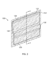
- a lock plate according to a first embodiment of the invention is designated generally by the reference numeral 100.
- the lock plate 100 comprises a first end 120 and an opposite second end 130, with a planar portion 140 extending between the first end 120 and the second end 130.
- the planar portion 140 comprises a first projection 150 that is positioned substantially mid-way between the first end 120 and the second end 130.
- the first projection 150 protrudes from a plane 142 that is defined by the planar portion 140.
- the first projection 150 protrudes from the plane 142 of the planar portion 140 by a distance that is at least equal to a thickness of the planar portion 140.
- the first end 120 comprises a lip portion 122 that extends out of the plane 142 defined by the planar portion 140 in the same direction as the first projection 150.
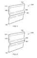
- Figure 3 shows a cross-section through the lock plate 100 of Figure 2 .
- the planar portion 140 has a constant thickness t across the first projection 150.
- the lock plate 100 is formed from a metal plate such as, for example, steel or a titanium alloy.
- the lock plate 100 can be readily formed using conventional metal sheet or plate forming techniques.
- a lock plate according to a second embodiment of the invention is designated generally by the reference numeral 200.
- Features of the lock plate 200 which correspond to those of lock plate 100 have been given corresponding reference numerals for ease of reference.
- the lock plate 200 has a first end 120 and an opposite second end 130, with a planar portion 240 extending between the first end 120 and the second end 130.
- the planar portion 240 comprises a first projection 250 that is positioned substantially mid-way between the first end 120 and the second end 130.
- the first projection 250 protrudes from a plane 142 that is defined by the planar portion 240.
- the planar portion 240 that lies in the plane 142 has a thickness t.
- the first projection 250 is thinned relative to the planar portion 240, and has a thickness t', where t' is less than t.
- a lock plate according to a third embodiment of the invention is designated generally by the reference numeral 300.
- Features of the lock plate 300 which correspond to those of lock plate 100 have been given corresponding reference numerals for ease of reference.
- the lock plate 300 has a first end 120 and an opposite second end 130, with a planar portion 340 extending between the first end 120 and the second end 130.
- the planar portion 340 comprises a first projection 350 that is positioned substantially mid-way between the first end 120 and the second end 130.
- the first projection 350 protrudes from a plane 142 (shown in Figure 2 ) that is defined by the planar portion 340.
- the first projection 350 includes a second projection 360 that extends along the length of the first projection 350 in a direction distal to the plane 142.
- a lock plate according to a fourth embodiment of the invention is designated generally by the reference numeral 400.
- Features of the lock plate 400 which correspond to those of lock plate 100 have been given corresponding reference numerals for ease of reference.
- the lock plate 400 has a first end 120 and an opposite second end 130, with a planar portion 440 extending between the first end 120 and the second end 130.
- the planar portion 440 comprises a 450 that is positioned substantially mid-way between the first end 120 and the second end 130.
- the first projection 450 protrudes from a plane 142 that is defined by the planar portion 440.
- the first projection 450 includes a groove 460 that extends along the length of the first projection 450 in a direction distal to the plane 142.
- a first component 20 and a second component 30 are aligned with one another and their relative position is fixed by means of a plurality of lock plates 100.
- the first component 20 is a turbine blade 20 and the second component is turbine disc 30.
- the assembled turbine blade 20 and turbine disc 30 may be disassembled by severing the first projection 150 of the lock plate 100.
- the severed parts of the lock plate 100 can be seen in Figure 7B .
- Figures 7A and 7B show the use of a lock plate according to the first embodiment of the invention, the method of use of the invention applies equally to any of the embodiments of the invention described hereinabove.
Landscapes
- Engineering & Computer Science (AREA)
- Mechanical Engineering (AREA)
- General Engineering & Computer Science (AREA)
- Turbine Rotor Nozzle Sealing (AREA)
- Laser Beam Processing (AREA)
- Connection Of Plates (AREA)
- Automatic Assembly (AREA)
Applications Claiming Priority (1)
| Application Number | Priority Date | Filing Date | Title |
|---|---|---|---|
| GB1309722.5A GB2511584B (en) | 2013-05-31 | 2013-05-31 | A lock plate |
Publications (2)
| Publication Number | Publication Date |
|---|---|
| EP2808489A1 true EP2808489A1 (de) | 2014-12-03 |
| EP2808489B1 EP2808489B1 (de) | 2018-02-21 |
Family
ID=48805529
Family Applications (1)
| Application Number | Title | Priority Date | Filing Date |
|---|---|---|---|
| EP14161664.9A Not-in-force EP2808489B1 (de) | 2013-05-31 | 2014-03-26 | Sicherungsplatte |
Country Status (3)
| Country | Link |
|---|---|
| US (1) | US9695700B2 (de) |
| EP (1) | EP2808489B1 (de) |
| GB (1) | GB2511584B (de) |
Families Citing this family (2)
| Publication number | Priority date | Publication date | Assignee | Title |
|---|---|---|---|---|
| JP6218232B2 (ja) * | 2014-03-14 | 2017-10-25 | 本田技研工業株式会社 | タービンホイール |
| CN110578557A (zh) * | 2019-10-29 | 2019-12-17 | 北京动力机械研究所 | 一种涡轮叶片锁紧装置及其装配方法 |
Citations (9)
| Publication number | Priority date | Publication date | Assignee | Title |
|---|---|---|---|---|
| US2641443A (en) * | 1951-03-17 | 1953-06-09 | A V Roe Canada Ltd | Rotor blade locking |
| DE1288364B (de) * | 1961-04-10 | 1969-01-30 | Gen Electric | Laufrad fuer Axialturbomaschinen, insbesondere Axialgasturbinen |
| US4767276A (en) * | 1986-12-19 | 1988-08-30 | General Electric Company | Retainer ring |
| US5256035A (en) * | 1992-06-01 | 1993-10-26 | United Technologies Corporation | Rotor blade retention and sealing construction |
| EP0609979A1 (de) * | 1993-02-03 | 1994-08-10 | ROLLS-ROYCE plc | Ausgewuchteter Rotor für eine Gasturbine |
| US6065932A (en) * | 1997-07-11 | 2000-05-23 | Rolls-Royce Plc | Turbine |
| US20050123405A1 (en) * | 2003-12-05 | 2005-06-09 | Honda Motor Co., Ltd. | Sealing arrangement for an axial turbine wheel |
| US20070217904A1 (en) * | 2006-03-14 | 2007-09-20 | Dixon Jeffrey A | Turbine engine cooling |
| US20090116965A1 (en) * | 2005-09-07 | 2009-05-07 | Dieter Brillert | Arrangement for axially securing rotating blades in a rotor, sealing element for such an arangement, and use of such an arrangement |
Family Cites Families (11)
| Publication number | Priority date | Publication date | Assignee | Title |
|---|---|---|---|---|
| US3043562A (en) * | 1961-04-10 | 1962-07-10 | Gen Electric | Combination sealing and restraining member for long-shank turbo-machine buckets |
| US3598503A (en) * | 1969-09-19 | 1971-08-10 | United Aircraft Corp | Blade lock |
| GB9517369D0 (en) * | 1995-08-24 | 1995-10-25 | Rolls Royce Plc | Bladed rotor |
| ITMI991210A1 (it) * | 1999-05-31 | 2000-12-01 | Nuovo Pignone Spa | Dispositivo di fissaggio per palette per turbine a gas |
| US6837686B2 (en) * | 2002-09-27 | 2005-01-04 | Pratt & Whitney Canada Corp. | Blade retention scheme using a retention tab |
| GB0423363D0 (en) * | 2004-10-21 | 2004-11-24 | Rolls Royce Plc | Rotor assembly retaining apparatus |
| DE102004054930A1 (de) * | 2004-11-13 | 2006-05-18 | Mtu Aero Engines Gmbh | Rotor einer Turbomaschine, insbesondere Gasturbinenrotor |
| DE102005035901A1 (de) * | 2005-07-30 | 2007-02-01 | Mtu Aero Engines Gmbh | Sicherungselement |
| EP1916389A1 (de) * | 2006-10-26 | 2008-04-30 | Siemens Aktiengesellschaft | Turbinenschaufel Anordnung |
| US8388309B2 (en) * | 2008-09-25 | 2013-03-05 | Siemens Energy, Inc. | Gas turbine sealing apparatus |
| US20130202433A1 (en) * | 2012-02-07 | 2013-08-08 | General Electric Company | Seal assembly for turbine coolant passageways |
-
2013
- 2013-05-31 GB GB1309722.5A patent/GB2511584B/en not_active Expired - Fee Related
-
2014
- 2014-03-26 EP EP14161664.9A patent/EP2808489B1/de not_active Not-in-force
- 2014-03-26 US US14/226,073 patent/US9695700B2/en not_active Expired - Fee Related
Patent Citations (9)
| Publication number | Priority date | Publication date | Assignee | Title |
|---|---|---|---|---|
| US2641443A (en) * | 1951-03-17 | 1953-06-09 | A V Roe Canada Ltd | Rotor blade locking |
| DE1288364B (de) * | 1961-04-10 | 1969-01-30 | Gen Electric | Laufrad fuer Axialturbomaschinen, insbesondere Axialgasturbinen |
| US4767276A (en) * | 1986-12-19 | 1988-08-30 | General Electric Company | Retainer ring |
| US5256035A (en) * | 1992-06-01 | 1993-10-26 | United Technologies Corporation | Rotor blade retention and sealing construction |
| EP0609979A1 (de) * | 1993-02-03 | 1994-08-10 | ROLLS-ROYCE plc | Ausgewuchteter Rotor für eine Gasturbine |
| US6065932A (en) * | 1997-07-11 | 2000-05-23 | Rolls-Royce Plc | Turbine |
| US20050123405A1 (en) * | 2003-12-05 | 2005-06-09 | Honda Motor Co., Ltd. | Sealing arrangement for an axial turbine wheel |
| US20090116965A1 (en) * | 2005-09-07 | 2009-05-07 | Dieter Brillert | Arrangement for axially securing rotating blades in a rotor, sealing element for such an arangement, and use of such an arrangement |
| US20070217904A1 (en) * | 2006-03-14 | 2007-09-20 | Dixon Jeffrey A | Turbine engine cooling |
Also Published As
| Publication number | Publication date |
|---|---|
| EP2808489B1 (de) | 2018-02-21 |
| US20140356175A1 (en) | 2014-12-04 |
| GB201309722D0 (en) | 2013-07-17 |
| GB2511584B (en) | 2015-03-11 |
| US9695700B2 (en) | 2017-07-04 |
| GB2511584A (en) | 2014-09-10 |
Similar Documents
| Publication | Publication Date | Title |
|---|---|---|
| US6109877A (en) | Turbine blade-to-disk retention device | |
| EP2500525A1 (de) | Dämpferbolzen | |
| JP6397828B2 (ja) | タービンロータディスクまたはターボ機械圧縮機ディスクなどの部品用にスロットをブローチ切削するためのブローチおよび方法 | |
| EP2562357B1 (de) | Austauschbare Stapeleinsatzanordnung und zugehöriges Verfahren | |
| EP2500524B1 (de) | Rotorschaufel eines Gasturbinentriebwerks und zugehörige Baugruppe | |
| EP2565398A2 (de) | Wellenanordnung für einen Gasturbinenmotor | |
| EP3347573B1 (de) | Dummy-radscheibe und verfahren zum bearbeiten von schaufeln | |
| EP3181279A1 (de) | C-typ-rohrschneider | |
| US9695700B2 (en) | Lock plate | |
| EP2862658A1 (de) | Verfahren zur herstellung eines verdichterlaufrades und verdichterlaufrad | |
| EP2299059B1 (de) | Tragflächenschaufelanordnung | |
| US10369645B2 (en) | Broaching cutter | |
| EP3006675B1 (de) | Verriegelungselement | |
| EP2921715A1 (de) | Schaufelreihengruppe | |
| US7540714B1 (en) | Device for blocking a ring for axially retaining a blade, associated rotor disk and retaining ring, and rotor and aircraft engine comprising them | |
| US9925607B2 (en) | Helical broach | |
| WO2007014543A1 (de) | Sicherungselement zur laufschaufelbefestigung | |
| CN111036991B (zh) | 片状磁钢类零件的加工方法 | |
| CN111819774A (zh) | 转子铁芯部件制造方法以及模具 | |
| EP3156135B1 (de) | Abdeckvorrichtung zur anbringung an einem bauteil |
Legal Events
| Date | Code | Title | Description |
|---|---|---|---|
| PUAI | Public reference made under article 153(3) epc to a published international application that has entered the european phase |
Free format text: ORIGINAL CODE: 0009012 |
|
| 17P | Request for examination filed |
Effective date: 20140326 |
|
| AK | Designated contracting states |
Kind code of ref document: A1 Designated state(s): AL AT BE BG CH CY CZ DE DK EE ES FI FR GB GR HR HU IE IS IT LI LT LU LV MC MK MT NL NO PL PT RO RS SE SI SK SM TR |
|
| AX | Request for extension of the european patent |
Extension state: BA ME |
|
| R17P | Request for examination filed (corrected) |
Effective date: 20150603 |
|
| RBV | Designated contracting states (corrected) |
Designated state(s): AL AT BE BG CH CY CZ DE DK EE ES FI FR GB GR HR HU IE IS IT LI LT LU LV MC MK MT NL NO PL PT RO RS SE SI SK SM TR |
|
| RAP1 | Party data changed (applicant data changed or rights of an application transferred) |
Owner name: ROLLS-ROYCE PLC |
|
| GRAP | Despatch of communication of intention to grant a patent |
Free format text: ORIGINAL CODE: EPIDOSNIGR1 |
|
| STAA | Information on the status of an ep patent application or granted ep patent |
Free format text: STATUS: GRANT OF PATENT IS INTENDED |
|
| INTG | Intention to grant announced |
Effective date: 20170920 |
|
| GRAS | Grant fee paid |
Free format text: ORIGINAL CODE: EPIDOSNIGR3 |
|
| GRAA | (expected) grant |
Free format text: ORIGINAL CODE: 0009210 |
|
| STAA | Information on the status of an ep patent application or granted ep patent |
Free format text: STATUS: THE PATENT HAS BEEN GRANTED |
|
| AK | Designated contracting states |
Kind code of ref document: B1 Designated state(s): AL AT BE BG CH CY CZ DE DK EE ES FI FR GB GR HR HU IE IS IT LI LT LU LV MC MK MT NL NO PL PT RO RS SE SI SK SM TR |
|
| REG | Reference to a national code |
Ref country code: GB Ref legal event code: FG4D |
|
| REG | Reference to a national code |
Ref country code: CH Ref legal event code: EP |
|
| REG | Reference to a national code |
Ref country code: AT Ref legal event code: REF Ref document number: 971942 Country of ref document: AT Kind code of ref document: T Effective date: 20180315 |
|
| REG | Reference to a national code |
Ref country code: IE Ref legal event code: FG4D |
|
| REG | Reference to a national code |
Ref country code: DE Ref legal event code: R096 Ref document number: 602014021101 Country of ref document: DE |
|
| REG | Reference to a national code |
Ref country code: FR Ref legal event code: PLFP Year of fee payment: 5 |
|
| REG | Reference to a national code |
Ref country code: NL Ref legal event code: MP Effective date: 20180221 |
|
| REG | Reference to a national code |
Ref country code: LT Ref legal event code: MG4D |
|
| REG | Reference to a national code |
Ref country code: AT Ref legal event code: MK05 Ref document number: 971942 Country of ref document: AT Kind code of ref document: T Effective date: 20180221 |
|
| PG25 | Lapsed in a contracting state [announced via postgrant information from national office to epo] |
Ref country code: ES Free format text: LAPSE BECAUSE OF FAILURE TO SUBMIT A TRANSLATION OF THE DESCRIPTION OR TO PAY THE FEE WITHIN THE PRESCRIBED TIME-LIMIT Effective date: 20180221 Ref country code: NO Free format text: LAPSE BECAUSE OF FAILURE TO SUBMIT A TRANSLATION OF THE DESCRIPTION OR TO PAY THE FEE WITHIN THE PRESCRIBED TIME-LIMIT Effective date: 20180521 Ref country code: FI Free format text: LAPSE BECAUSE OF FAILURE TO SUBMIT A TRANSLATION OF THE DESCRIPTION OR TO PAY THE FEE WITHIN THE PRESCRIBED TIME-LIMIT Effective date: 20180221 Ref country code: CY Free format text: LAPSE BECAUSE OF FAILURE TO SUBMIT A TRANSLATION OF THE DESCRIPTION OR TO PAY THE FEE WITHIN THE PRESCRIBED TIME-LIMIT Effective date: 20180221 Ref country code: LT Free format text: LAPSE BECAUSE OF FAILURE TO SUBMIT A TRANSLATION OF THE DESCRIPTION OR TO PAY THE FEE WITHIN THE PRESCRIBED TIME-LIMIT Effective date: 20180221 Ref country code: NL Free format text: LAPSE BECAUSE OF FAILURE TO SUBMIT A TRANSLATION OF THE DESCRIPTION OR TO PAY THE FEE WITHIN THE PRESCRIBED TIME-LIMIT Effective date: 20180221 Ref country code: HR Free format text: LAPSE BECAUSE OF FAILURE TO SUBMIT A TRANSLATION OF THE DESCRIPTION OR TO PAY THE FEE WITHIN THE PRESCRIBED TIME-LIMIT Effective date: 20180221 |
|
| PG25 | Lapsed in a contracting state [announced via postgrant information from national office to epo] |
Ref country code: BG Free format text: LAPSE BECAUSE OF FAILURE TO SUBMIT A TRANSLATION OF THE DESCRIPTION OR TO PAY THE FEE WITHIN THE PRESCRIBED TIME-LIMIT Effective date: 20180521 Ref country code: AT Free format text: LAPSE BECAUSE OF FAILURE TO SUBMIT A TRANSLATION OF THE DESCRIPTION OR TO PAY THE FEE WITHIN THE PRESCRIBED TIME-LIMIT Effective date: 20180221 Ref country code: RS Free format text: LAPSE BECAUSE OF FAILURE TO SUBMIT A TRANSLATION OF THE DESCRIPTION OR TO PAY THE FEE WITHIN THE PRESCRIBED TIME-LIMIT Effective date: 20180221 Ref country code: SE Free format text: LAPSE BECAUSE OF FAILURE TO SUBMIT A TRANSLATION OF THE DESCRIPTION OR TO PAY THE FEE WITHIN THE PRESCRIBED TIME-LIMIT Effective date: 20180221 Ref country code: LV Free format text: LAPSE BECAUSE OF FAILURE TO SUBMIT A TRANSLATION OF THE DESCRIPTION OR TO PAY THE FEE WITHIN THE PRESCRIBED TIME-LIMIT Effective date: 20180221 Ref country code: GR Free format text: LAPSE BECAUSE OF FAILURE TO SUBMIT A TRANSLATION OF THE DESCRIPTION OR TO PAY THE FEE WITHIN THE PRESCRIBED TIME-LIMIT Effective date: 20180522 |
|
| PG25 | Lapsed in a contracting state [announced via postgrant information from national office to epo] |
Ref country code: IT Free format text: LAPSE BECAUSE OF FAILURE TO SUBMIT A TRANSLATION OF THE DESCRIPTION OR TO PAY THE FEE WITHIN THE PRESCRIBED TIME-LIMIT Effective date: 20180221 Ref country code: EE Free format text: LAPSE BECAUSE OF FAILURE TO SUBMIT A TRANSLATION OF THE DESCRIPTION OR TO PAY THE FEE WITHIN THE PRESCRIBED TIME-LIMIT Effective date: 20180221 Ref country code: RO Free format text: LAPSE BECAUSE OF FAILURE TO SUBMIT A TRANSLATION OF THE DESCRIPTION OR TO PAY THE FEE WITHIN THE PRESCRIBED TIME-LIMIT Effective date: 20180221 Ref country code: PL Free format text: LAPSE BECAUSE OF FAILURE TO SUBMIT A TRANSLATION OF THE DESCRIPTION OR TO PAY THE FEE WITHIN THE PRESCRIBED TIME-LIMIT Effective date: 20180221 Ref country code: AL Free format text: LAPSE BECAUSE OF FAILURE TO SUBMIT A TRANSLATION OF THE DESCRIPTION OR TO PAY THE FEE WITHIN THE PRESCRIBED TIME-LIMIT Effective date: 20180221 |
|
| REG | Reference to a national code |
Ref country code: CH Ref legal event code: PL |
|
| REG | Reference to a national code |
Ref country code: DE Ref legal event code: R097 Ref document number: 602014021101 Country of ref document: DE |
|
| PG25 | Lapsed in a contracting state [announced via postgrant information from national office to epo] |
Ref country code: DK Free format text: LAPSE BECAUSE OF FAILURE TO SUBMIT A TRANSLATION OF THE DESCRIPTION OR TO PAY THE FEE WITHIN THE PRESCRIBED TIME-LIMIT Effective date: 20180221 Ref country code: SM Free format text: LAPSE BECAUSE OF FAILURE TO SUBMIT A TRANSLATION OF THE DESCRIPTION OR TO PAY THE FEE WITHIN THE PRESCRIBED TIME-LIMIT Effective date: 20180221 Ref country code: MC Free format text: LAPSE BECAUSE OF FAILURE TO SUBMIT A TRANSLATION OF THE DESCRIPTION OR TO PAY THE FEE WITHIN THE PRESCRIBED TIME-LIMIT Effective date: 20180221 Ref country code: SK Free format text: LAPSE BECAUSE OF FAILURE TO SUBMIT A TRANSLATION OF THE DESCRIPTION OR TO PAY THE FEE WITHIN THE PRESCRIBED TIME-LIMIT Effective date: 20180221 Ref country code: CZ Free format text: LAPSE BECAUSE OF FAILURE TO SUBMIT A TRANSLATION OF THE DESCRIPTION OR TO PAY THE FEE WITHIN THE PRESCRIBED TIME-LIMIT Effective date: 20180221 |
|
| REG | Reference to a national code |
Ref country code: BE Ref legal event code: MM Effective date: 20180331 |
|
| REG | Reference to a national code |
Ref country code: IE Ref legal event code: MM4A |
|
| PLBE | No opposition filed within time limit |
Free format text: ORIGINAL CODE: 0009261 |
|
| STAA | Information on the status of an ep patent application or granted ep patent |
Free format text: STATUS: NO OPPOSITION FILED WITHIN TIME LIMIT |
|
| PG25 | Lapsed in a contracting state [announced via postgrant information from national office to epo] |
Ref country code: LU Free format text: LAPSE BECAUSE OF NON-PAYMENT OF DUE FEES Effective date: 20180326 |
|
| 26N | No opposition filed |
Effective date: 20181122 |
|
| PG25 | Lapsed in a contracting state [announced via postgrant information from national office to epo] |
Ref country code: IE Free format text: LAPSE BECAUSE OF NON-PAYMENT OF DUE FEES Effective date: 20180326 |
|
| PG25 | Lapsed in a contracting state [announced via postgrant information from national office to epo] |
Ref country code: LI Free format text: LAPSE BECAUSE OF NON-PAYMENT OF DUE FEES Effective date: 20180331 Ref country code: SI Free format text: LAPSE BECAUSE OF FAILURE TO SUBMIT A TRANSLATION OF THE DESCRIPTION OR TO PAY THE FEE WITHIN THE PRESCRIBED TIME-LIMIT Effective date: 20180221 Ref country code: BE Free format text: LAPSE BECAUSE OF NON-PAYMENT OF DUE FEES Effective date: 20180331 Ref country code: CH Free format text: LAPSE BECAUSE OF NON-PAYMENT OF DUE FEES Effective date: 20180331 |
|
| PG25 | Lapsed in a contracting state [announced via postgrant information from national office to epo] |
Ref country code: MT Free format text: LAPSE BECAUSE OF NON-PAYMENT OF DUE FEES Effective date: 20180326 |
|
| PG25 | Lapsed in a contracting state [announced via postgrant information from national office to epo] |
Ref country code: TR Free format text: LAPSE BECAUSE OF FAILURE TO SUBMIT A TRANSLATION OF THE DESCRIPTION OR TO PAY THE FEE WITHIN THE PRESCRIBED TIME-LIMIT Effective date: 20180221 |
|
| PGFP | Annual fee paid to national office [announced via postgrant information from national office to epo] |
Ref country code: DE Payment date: 20200327 Year of fee payment: 7 Ref country code: GB Payment date: 20200327 Year of fee payment: 7 |
|
| PG25 | Lapsed in a contracting state [announced via postgrant information from national office to epo] |
Ref country code: PT Free format text: LAPSE BECAUSE OF FAILURE TO SUBMIT A TRANSLATION OF THE DESCRIPTION OR TO PAY THE FEE WITHIN THE PRESCRIBED TIME-LIMIT Effective date: 20180221 Ref country code: HU Free format text: LAPSE BECAUSE OF FAILURE TO SUBMIT A TRANSLATION OF THE DESCRIPTION OR TO PAY THE FEE WITHIN THE PRESCRIBED TIME-LIMIT; INVALID AB INITIO Effective date: 20140326 |
|
| PG25 | Lapsed in a contracting state [announced via postgrant information from national office to epo] |
Ref country code: MK Free format text: LAPSE BECAUSE OF NON-PAYMENT OF DUE FEES Effective date: 20180221 |
|
| PGFP | Annual fee paid to national office [announced via postgrant information from national office to epo] |
Ref country code: FR Payment date: 20200325 Year of fee payment: 7 |
|
| PG25 | Lapsed in a contracting state [announced via postgrant information from national office to epo] |
Ref country code: IS Free format text: LAPSE BECAUSE OF FAILURE TO SUBMIT A TRANSLATION OF THE DESCRIPTION OR TO PAY THE FEE WITHIN THE PRESCRIBED TIME-LIMIT Effective date: 20180621 |
|
| REG | Reference to a national code |
Ref country code: DE Ref legal event code: R119 Ref document number: 602014021101 Country of ref document: DE |
|
| GBPC | Gb: european patent ceased through non-payment of renewal fee |
Effective date: 20210326 |
|
| PG25 | Lapsed in a contracting state [announced via postgrant information from national office to epo] |
Ref country code: DE Free format text: LAPSE BECAUSE OF NON-PAYMENT OF DUE FEES Effective date: 20211001 Ref country code: GB Free format text: LAPSE BECAUSE OF NON-PAYMENT OF DUE FEES Effective date: 20210326 Ref country code: FR Free format text: LAPSE BECAUSE OF NON-PAYMENT OF DUE FEES Effective date: 20210331 |