EP2808296A2 - Light deflector, light deflector manufacturing method and optical scanning device - Google Patents
Light deflector, light deflector manufacturing method and optical scanning device Download PDFInfo
- Publication number
- EP2808296A2 EP2808296A2 EP20140001863 EP14001863A EP2808296A2 EP 2808296 A2 EP2808296 A2 EP 2808296A2 EP 20140001863 EP20140001863 EP 20140001863 EP 14001863 A EP14001863 A EP 14001863A EP 2808296 A2 EP2808296 A2 EP 2808296A2
- Authority
- EP
- European Patent Office
- Prior art keywords
- torsion bar
- light deflector
- supporting
- mirror
- supporting member
- Prior art date
- Legal status (The legal status is an assumption and is not a legal conclusion. Google has not performed a legal analysis and makes no representation as to the accuracy of the status listed.)
- Granted
Links
- 230000003287 optical effect Effects 0.000 title claims description 15
- 238000004519 manufacturing process Methods 0.000 title claims description 12
- 238000000034 method Methods 0.000 claims description 14
- XUIMIQQOPSSXEZ-UHFFFAOYSA-N Silicon Chemical compound [Si] XUIMIQQOPSSXEZ-UHFFFAOYSA-N 0.000 claims description 12
- 229910052710 silicon Inorganic materials 0.000 claims description 12
- 239000010703 silicon Substances 0.000 claims description 12
- 239000012530 fluid Substances 0.000 claims description 10
- 239000000853 adhesive Substances 0.000 claims description 9
- 230000001070 adhesive effect Effects 0.000 claims description 9
- 239000000758 substrate Substances 0.000 claims description 6
- VYPSYNLAJGMNEJ-UHFFFAOYSA-N Silicium dioxide Chemical compound O=[Si]=O VYPSYNLAJGMNEJ-UHFFFAOYSA-N 0.000 claims description 5
- 229910052814 silicon oxide Inorganic materials 0.000 claims description 5
- 230000001678 irradiating effect Effects 0.000 claims description 3
- 230000003014 reinforcing effect Effects 0.000 claims description 3
- 238000012545 processing Methods 0.000 claims description 2
- 230000006870 function Effects 0.000 description 13
- 238000004891 communication Methods 0.000 description 8
- 238000010586 diagram Methods 0.000 description 8
- 239000010409 thin film Substances 0.000 description 7
- 230000008859 change Effects 0.000 description 6
- 230000005484 gravity Effects 0.000 description 4
- 230000002093 peripheral effect Effects 0.000 description 4
- 230000008569 process Effects 0.000 description 4
- 230000005540 biological transmission Effects 0.000 description 3
- 239000010408 film Substances 0.000 description 3
- 239000002245 particle Substances 0.000 description 3
- 230000008901 benefit Effects 0.000 description 2
- 230000008602 contraction Effects 0.000 description 2
- 238000005520 cutting process Methods 0.000 description 2
- 238000005530 etching Methods 0.000 description 2
- 238000012986 modification Methods 0.000 description 2
- 230000004048 modification Effects 0.000 description 2
- 238000012544 monitoring process Methods 0.000 description 2
- 230000004044 response Effects 0.000 description 2
- 238000012546 transfer Methods 0.000 description 2
- 239000000470 constituent Substances 0.000 description 1
- 230000007423 decrease Effects 0.000 description 1
- 238000000151 deposition Methods 0.000 description 1
- 238000013461 design Methods 0.000 description 1
- 238000007599 discharging Methods 0.000 description 1
- 230000000694 effects Effects 0.000 description 1
- 239000011521 glass Substances 0.000 description 1
- 239000012212 insulator Substances 0.000 description 1
- 239000007788 liquid Substances 0.000 description 1
- 238000005259 measurement Methods 0.000 description 1
- 239000012780 transparent material Substances 0.000 description 1
Images





Classifications
-
- G—PHYSICS
- G02—OPTICS
- G02B—OPTICAL ELEMENTS, SYSTEMS OR APPARATUS
- G02B26/00—Optical devices or arrangements for the control of light using movable or deformable optical elements
- G02B26/08—Optical devices or arrangements for the control of light using movable or deformable optical elements for controlling the direction of light
- G02B26/10—Scanning systems
- G02B26/105—Scanning systems with one or more pivoting mirrors or galvano-mirrors
-
- B—PERFORMING OPERATIONS; TRANSPORTING
- B81—MICROSTRUCTURAL TECHNOLOGY
- B81B—MICROSTRUCTURAL DEVICES OR SYSTEMS, e.g. MICROMECHANICAL DEVICES
- B81B3/00—Devices comprising flexible or deformable elements, e.g. comprising elastic tongues or membranes
- B81B3/0035—Constitution or structural means for controlling the movement of the flexible or deformable elements
- B81B3/004—Angular deflection
- B81B3/0045—Improve properties related to angular swinging, e.g. control resonance frequency
-
- G—PHYSICS
- G02—OPTICS
- G02B—OPTICAL ELEMENTS, SYSTEMS OR APPARATUS
- G02B26/00—Optical devices or arrangements for the control of light using movable or deformable optical elements
- G02B26/08—Optical devices or arrangements for the control of light using movable or deformable optical elements for controlling the direction of light
- G02B26/0816—Optical devices or arrangements for the control of light using movable or deformable optical elements for controlling the direction of light by means of one or more reflecting elements
- G02B26/0833—Optical devices or arrangements for the control of light using movable or deformable optical elements for controlling the direction of light by means of one or more reflecting elements the reflecting element being a micromechanical device, e.g. a MEMS mirror, DMD
- G02B26/0858—Optical devices or arrangements for the control of light using movable or deformable optical elements for controlling the direction of light by means of one or more reflecting elements the reflecting element being a micromechanical device, e.g. a MEMS mirror, DMD the reflecting means being moved or deformed by piezoelectric means
-
- B—PERFORMING OPERATIONS; TRANSPORTING
- B81—MICROSTRUCTURAL TECHNOLOGY
- B81B—MICROSTRUCTURAL DEVICES OR SYSTEMS, e.g. MICROMECHANICAL DEVICES
- B81B2201/00—Specific applications of microelectromechanical systems
- B81B2201/04—Optical MEMS
- B81B2201/042—Micromirrors, not used as optical switches
-
- B—PERFORMING OPERATIONS; TRANSPORTING
- B81—MICROSTRUCTURAL TECHNOLOGY
- B81B—MICROSTRUCTURAL DEVICES OR SYSTEMS, e.g. MICROMECHANICAL DEVICES
- B81B2203/00—Basic microelectromechanical structures
- B81B2203/01—Suspended structures, i.e. structures allowing a movement
- B81B2203/0109—Bridges
-
- B—PERFORMING OPERATIONS; TRANSPORTING
- B81—MICROSTRUCTURAL TECHNOLOGY
- B81B—MICROSTRUCTURAL DEVICES OR SYSTEMS, e.g. MICROMECHANICAL DEVICES
- B81B2203/00—Basic microelectromechanical structures
- B81B2203/01—Suspended structures, i.e. structures allowing a movement
- B81B2203/0145—Flexible holders
- B81B2203/0154—Torsion bars
Definitions
- the present disclosure relates to a light deflector used in forming an electrostatic latent image and the like, a light deflector manufacturing method and an optical scanning device with such a light deflector.
- a light beam modulated in accordance with image data is generated, reflected and deflected, whereby an image bearing member such as a photoconductive drum is scanned with the deflected light beam to form an electrostatic latent image.
- the light deflector is a device for reflecting and deflecting a light beam.
- a technique using MEMS (Micro Electro Mechanical Systems) mirrors as a light deflector instead of a polygon mirror has been proposed.
- the MEMS mirrors have an advantage of speeded-up scanning, low power consumption and the like.
- the light deflector using the MEMS mirrors includes a torsion bar, mirror portions swingable about an axis of the torsion bar and mirror drivers.
- the mirror drivers Upon the input of drive signals to the mirror drivers, the mirror drivers resonate (vibrate) movable portions of the MEMS mirrors to swing the mirror portions about the axis of the torsion bar and, in this state, a light beam incident on the mirror portions is reflected and deflected to scan the light beam.
- the movable portion of the MEMS mirror is, in other words, a vibration system of the MEMS mirror and configured by the mirror portion and the torsion bar.
- a resonant frequency of the movable portion of the MEMS mirror (hereinafter, merely referred to as a resonance frequency in some cases) needs to be adjusted for each MEMS mirror. This is because a maximum deflection angle of the mirror portion differs for each MEMS mirror if the resonant frequency differs.
- the resonant frequency is determined by a moment of inertia of the mirror portion, a spring constant of the torsion bar and the like.
- the resonant frequency changes if these physical quantities only slightly differ.
- dimensions of the mirror portion affect the moment of inertia of the mirror portion, and the resonant frequency changes if the dimensions of the mirror portion differ from design values by several microns. Since errors in the above physical quantities unavoidably occur in the manufacturing of the MEMS mirror, the resonant frequency needs to be adjusted.
- the former technique adjusts the resonant frequency by providing a first area and a second area, which are symmetrical with respect to a torsion bar, forming a plurality of mass bodies in advance in the respective areas, selectively cutting off the mass body by a laser beam to reduce the mass of the movable portion of the MEMS mirror.
- the latter technique adjusts the resonant frequency by making the mirror portion larger toward both left and right sides, providing a first area and a second area symmetrical with respect to a torsion bar, depositing and curing a liquid in each area to selectively form a mass body and increase the mass of the movable portion of the MEMS mirror.
- a moment of inertia is a value obtained by multiplying a square of a distance between the mass body and the axis of the torsion bar by a mass of the mass body.
- the mass body is located at a distance from the axis of the torsion bar.
- the present disclosure aims to provide a light deflector capable of improving accuracy in adjusting a resonant frequency of a movable portion of the light deflector, a light deflector manufacturing method and an optical scanning device with such a light deflector.
- a light deflector includes a fixing portion and a movable portion.
- the movable portion includes a mirror portion for deflecting light by swinging about a predetermined swing axis, a torsion bar fixedly supported on the fixing portion and having an axis serving as the swing axis, and a supporting body configured to support the mirror portion and fixed to the torsion bar.
- the supporting body includes a hole portion through which the axis passes.
- a mass body for adjusting a resonant frequency of the movable portion is arranged in the hole portion.
- a light deflector manufacturing method includes a first step, a second step and a third step.
- the mirror portion is swung by inputting a drive signal to the light deflector in a state where the mass body is not arranged in the hole portion.
- the mass body is supplied in a fluid state to the hole portion during the execution of the first step.
- the supply of the mass body is stopped when the resonant frequency of the movable portion reaches a predetermined value during the execution of the second step.
- An optical scanning device includes the above light deflector and a light source for irradiating a light beam to the mirror portion.
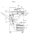
- FIG. 1 is a diagram schematically showing an internal structure of an image forming apparatus 1 to which a light deflector according to the embodiment is applied.
- the image forming apparatus 1 can be, for example, applied to a digital complex machine having copier, printer, scanner and facsimile functions.
- the image forming apparatus 1 includes an apparatus main body 100, a document reading unit 200 arranged atop the apparatus main body 100, a document feeding unit 300 arranged atop the document reading unit 200 and an operation unit 400 arranged on the front surface of an upper part of the apparatus main body 100.
- the document feeding unit 300 functions as an automatic document feeder and can successively feed a plurality of documents placed on a document placing portion 301 to the document reading unit 200.
- the document reading unit 200 includes a carriage 201 carrying an exposure lamp and the like, a document platen 203 made of a transparent material such as glass, an unillustrated CCD (Charge Coupled Device) sensor and a document reading slit 205.
- the CCD sensor In the case of reading a document placed on the document platen 203, the document is read by the CCD sensor while the carriage 201 is moved in a longitudinal direction of the document platen 203. Contrary to this, in the case of reading a document fed from the document feeding unit 300, the carriage 201 is moved to a position facing the document reading slit 205 and the document fed from the document feeding unit 300 is read by the CCD sensor through the document reading slit 205.
- the CCD sensor outputs an image of the read document as image data.
- the apparatus main body 100 includes a sheet storing unit 101, an image forming unit 103 and a fixing unit 105.
- the sheet storing unit 101 is arranged in a lowest part of the apparatus main body 100 and includes sheet cassettes 107 capable of storing a stack of sheets.
- the uppermost sheet of the stack of sheets stored in the sheet cassette 107 is fed to a sheet conveyance path 111 by driving a pickup roller 109.
- the sheet is conveyed to the image forming unit 103 through the sheet conveyance path 111.
- the image forming unit 103 forms a toner image on a sheet conveyed thereto.
- the image forming unit 103 includes a photoconductive drum 113, an optical scanning device 115, a developing unit 117 and a transfer unit 119.
- the optical scanning device 115 generates light modulated in accordance with image data (image data output from the document reading unit 200, image data transmitted from a personal computer, facsimile-received image data or the like) and irradiates the light to the peripheral surface of the uniformly charged photoconductive drum 113. This causes an electrostatic latent image corresponding to the image data to be formed on the peripheral surface of the photoconductive drum 113.
- toner is supplied from the developing unit 117 to the peripheral surface of the photoconductive drum 113, whereby a toner image corresponding to the image data is formed on the peripheral surface.
- This toner image is transferred to a sheet conveyed from the sheet storing unit 101 described above by the transfer unit 119.
- the sheet having the toner image transferred thereto is conveyed to the fixing unit 105.
- the fixing unit 105 heat and pressure are applied to the toner image and the sheet to fix the toner image to the sheet.
- the sheet is discharged to a stack tray 121 or a sheet discharge tray 123.
- the operation unit 400 includes an operation key unit 401 and a display unit 403.
- the display unit 403 has a touch panel function and displays a screen including soft keys. A user makes settings necessary to perform a function such as a copy function by operating the soft keys while viewing the screen.
- the operation key unit 401 includes operation keys which are hard keys, specifically a start key 405, a numerical keypad 407, a stop key 409, a reset key 411, function changeover keys 413 for switching the function among copier, printer, scanner and facsimile functions and the like.
- the start key 405 is a key for starting an operation such as copying or facsimile transmission.
- the numerical keypad 407 is a keypad for entering numbers such as the number of copies and facsimile numbers.
- the stop key 409 is a key for stopping a copying operation and the like on the way.
- the reset key 411 is a key for returning the set content to an initial setting state.
- the function changeover keys 413 are keys including a copy key, a transmit key and the like and configured to switch a copy function, a transmit function and the like from one to another. If the copy key is operated, an initial screen for copying is displayed on the display unit 403. If the transmit key is operated, an initial screen for facsimile transmission and mail transmission is displayed on the display unit 403.
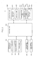
- FIG. 2 is a block diagram showing the configuration of the image forming apparatus 1 shown in FIG. 1.
- the image forming apparatus 1 is so configured that the document reading unit 200, the document feeding unit 300, the operation unit 400, a control unit 500 and a communication unit 600 are connected to each other by a bus.
- the apparatus main body 100, the document reading unit 200, the document feeding unit 300 and the operation unit 400 are not described since being already described.
- the control unit 500 includes a CPU (Central Processing Unit), a ROM (Read Only Memory), a RAM (Random Access Memory), an image memory and the like.
- the CPU executes a control necessary to operate the image forming apparatus 1 on the above constituent elements of the image forming apparatus 1 such as the apparatus main body 100.
- the ROM stores software necessary to control the operation of the image forming apparatus 1.
- the RAM is used such as to temporarily store data generated during the execution of the software and store application software.
- the image memory temporarily stores image data (image data output from the document reading unit 200, image data transmitted from a personal computer, facsimile-received image data or the like).
- the communication unit 600 includes a facsimile communication unit 601 and a network I/F unit 603.
- the facsimile communication unit 601 includes an NCU (Network Control Unit) for controlling a telephone line connection with a destination facsimile machine and a modulation/demodulation circuit for modulating/demodulating a signal for facsimile communication.
- the facsimile communication unit 601 is connected to a telephone line 605.
- the network I/F unit 603 is connected to a LAN (Local Area Network) 607.
- the network I/F unit 603 is a communication interface circuit for carrying out communication with terminal units such as personal computers connected to the LAN 607.
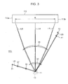
- FIG. 3 is a diagram showing an arrangement relationship of optical components constituting the optical scanning device 115.
- the optical scanning device 115 includes a light source 31, a light deflector 10, two scanning lenses 33, 35 and the like.
- the light source 31 is, for example, a laser diode and emits a light beam LB modulated in accordance with image data.
- a collimator lens 37 and a cylindrical lens 39 are arranged on an optical path between the light source 31 and the light deflector 10.
- the collimator lens 37 converts the light beam LB emitted from the light source 31 into a parallel beam.
- the cylindrical lens 39 linearly condenses the light beam LB converted into the parallel beam.
- the linearly condensed light beam LB is incident on the light deflector 10.
- the scanning lenses 33, 35 are arranged on an optical path between the light deflector 10 and the photoconductive drum 113.
- the light beam LB incident on a mirror portion 11 of the light deflector 10 is reflected and deflected by the mirror portion 11 and focused on the photoconductive drum 113 by the scanning lenses 33, 35. That is, by scanning the light beam LB across the photoconductive drum 113, an electrostatic latent image is formed on the photoconductive drum 113.
- the optical scanning device 115 further includes a BD lens 41 and a BD sensor 43.
- the light beam LB is scanned across the photoconductive drum 113 from one lateral part 113a to another lateral part 113b of the photoconductive drum 113, and the light beam LB beyond an effective scanning range is condensed by the BD lens 41 and received by the BD sensor 43.
- the BD (Beam Detect) sensor 43 generates a BD signal serving as a reference for the start of scanning (main scanning) on the photoconductive drum 113.
- FIG. 4 is a perspective view of the light deflector 10 according to the embodiment
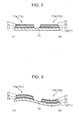
- FIG. 5 is a sectional view cut along a line A1-A2 showing the light deflector shown in FIG. 4.
- the light deflector 10 according to this embodiment is a piezoelectrically driven MEMS mirror.
- the MEMS mirror usable as the light deflector 10 is not limited to the piezoelectrically driven one.
- the light deflector 10 includes the mirror portion 11, a frame 13, a torsion bar 15, mirror drivers 17a, 17b, 17c and 17d, and a supporting body 31.
- the frame 13 has a rectangular shape.
- the frame 13 is composed of a pair of side portions 13c, 13d extending in a longitudinal direction, a pair of side portions 13a, 13b extending in a direction perpendicular to the longitudinal direction, and beams 19, 21 (fixing portion) connecting the side portions 13c, 13d.
- the mirror portion 11 is arranged in a central part of the frame 13.
- the mirror portion 11 has an elliptical shape whose minor axis direction matches the longitudinal direction of the frame 13.
- the torsion bar 15 has an axis AX extending in one direction and serving as a rotation axis (can be also referred to as a torsional rotation axis or a swing axis).
- the torsion bar 15 includes a first torsion bar 15a and a second torsion bar 15b extending along the common axis AX.
- the first and second torsion bars 15a, 15b extend in the minor axis direction of the elliptical shape of the mirror portion 11.
- One end of the first torsion bar 15a is fixed and supported by the beam 19 and one end of the second torsion bar 15b is fixed and supported by the beam 21.
- a space 33 is formed between the beam 19 and the side portion 13a, and a space 35 is formed between the beam 21 and the side portion 13b.
- the supporting body 31 supporting the mirror portion 11 is fixed to the other ends of the first and second torsion bars 15a, 15b.
- the supporting body 31 is arranged in the frame 13.
- the supporting body 31 has a rectangular shape and a longitudinal direction thereof is perpendicular to that of the frame 13.
- the beams 19, 21 fix and support the torsion bar 15 in such a manner that the mirror portion 11 supported by the supporting body 31 is swingable about the axis AX of the torsion bar 15.
- the mirror portion 11 deflects light by swinging about a predetermined swing axis
- the torsion bar 15 is fixed and supported by the fixing portion (beams 19, 21) and has the axis AX serving as the swing axis
- the supporting body 31 supports the mirror portion 11 and is fixed to the torsion bar 15.
- the mirror driver 17a is formed on a side closer to the side portion 13c than the torsion bar 15 and the mirror driver 17b is formed on a side closer to the side portion 13d than the torsion bar 15.
- the mirror driver 17c is formed on a side closer to the side portion 13c than the torsion bar 15 and the mirror driver 17d is formed on a side closer to the side portion 13d than the torsion bar 15.
- the mirror driver 17a is composed of a lower electrode 23, a PZT thin film 25 and an upper electrode 27.
- the mirror drivers 17b, 17c and 17d have the same configuration as the mirror driver 17a.
- the mirror drivers 17a, 17b, 17c and 17d are written as the mirror drivers 17 below unless it is necessary to distinguish them.
- FIG. 6 is a view showing a state where a drive voltage is applied to the mirror drivers 17 so that the PZT thin films 25 of the mirror drivers 17a, 17c extend and those of the mirror drivers 17b, 17d contract in the same cross-section as in FIG. 5.
- the beams 19, 21 are bended, whereby the mirror portion 11 is inclined together with the torsion bar 15.
- the extension of the PZT thin films 25 of the mirror drivers 17a, 17c and the contraction of the PZT thin films 25 of the mirror drivers 17b, 17d are described as a first movement and the contraction of the PZT thin films 25 of the mirror drivers 17a, 17c and the extension of the PZT thin films 25 of the mirror drivers 17b, 17d are described as a second movement below.
- the mirror portion 11 supported by the supporting body 31 swings about the axis AX of the torsion bar 15 to vary a deflection angle ⁇ .
- NL in FIG. 4 denotes a normal to the mirror portion 11 when the mirror portion 11 is not swinging.
- the mirror portion 11 When a frequency of the drive voltage is caused to match a resonant frequency, the mirror portion 11 resonates and a maximum value of the deflection angle ⁇ (maximum deflection angle) can be increased. By reflecting and deflecting a light beam by the mirror portion 11 in a state where the mirror portion 11 is resonated, the light beam is scanned across the photoconductive drum 113.
- FIG. 7 is a perspective view showing the mirror portion 11, the torsion bar 15, the supporting body 31 and a movable portion 37 with a first rib 39a and a second rib 39b provided in the light deflector 10 when viewed from the side of a top surface 11a (light beam reflecting/deflecting surface) of the mirror portion 11.
- FIG. 8 is a perspective view showing this movable portion 37 viewed from the side of an under surface 11b of the mirror portion 11.
- the top surface 11a of the mirror portion 11 is on the side of one surface 32a (supporting surface) of the supporting body 31, and the under surface 11b of the mirror portion 11 is supported by the one surface 32a of the supporting body 31.
- the supporting body 31 has a rectangular frame-like shape and includes a first supporting member 31a, a second supporting member 31 b, a third supporting member 31c and a fourth supporting member 31d which serve as four sides forming a rectangle.
- the first and second supporting members 31a, 31b extend straight in a direction intersecting with an extending direction of the torsion bar 15 and are arranged to face each other.
- the third and fourth supporting members 31 c, 31 d extend straight in the same direction as the extending direction of the torsion bar 15 and are symmetrically arranged with respect to the torsion bar 15.
- a space 41 is defined by the first, second, third and fourth supporting members 31a, 31b, 31c and 31d.
- the supporting body 31 is made lighter by providing the space 41.
- the supporting body 31 includes the first supporting member 31 a extending in the direction intersecting with the torsion bar 15, the second supporting member 31b arranged to face the first supporting member 31a and extending in the direction intersecting with the torsion bar 15, the third supporting member 31c connecting the first and second supporting members 31a, 31 b and the fourth supporting member 31d symmetrically arranged to the third supporting member 31 c with respect to the axis of the torsion bar 15 and connecting the first and second supporting members 31a, 31b.
- the supporting body 31 further includes a fifth supporting member 31e arranged in the space 41.
- the fifth supporting member 31e includes a main body portion 311, a first connecting portion 312 and a second connecting portion 313.
- the main body portion 311 is a main body of the fifth supporting member 31e and formed with a circular cavity which functions as a hole portion 53. This makes the supporting body 31 lighter.
- the mirror portion 11 is a plate-like member including a deflecting surface (top surface 11a) for deflecting light and a non-deflecting surface (under surface 11b) opposite to the deflecting surface.
- the non-deflecting surface (under surface 11b) forms the bottom of the hole portion 53.
- the first connecting portion 312 is arranged on a major axis of the main body portion 311 and connects one end part of the main body portion 311 and a center of the third supporting member 31c.
- the second connecting portion 313 is arranged on the major axis of the main body portion 311 and connects the other end part of the main body portion 311 and a center of the fourth supporting member 31d.
- the torsion bar 15 is composed of the first and second torsion bars 15a, 15b.
- the first and second torsion bars 15a, 15b extend in the same direction and are arranged with a spacing provided therebetween.
- the supporting body 31 is arranged in an area including this spacing.
- the first torsion bar 15a is fixed to the first supporting member 31a in a center of the first supporting member 31a.
- the second torsion bar 15b is fixed to the second supporting member 31 b in a center of the second supporting member 31b.
- each of the first, second, third, fourth and fifth supporting members 31 a, 31b, 31 c, 31 d and 31e and the first and second torsion bars 15a, 15b includes a planar portion facing toward the side of the one surface 32a of the supporting body 31, and each planar portion is located on the same plane. These have the same height (i.e. same thickness).
- the mirror portion 11 is provided on the one surface 32a of the supporting body 31.
- the mirror portion 11 is bonded to the third, fourth and fifth supporting members 3 1 c, 31 d and 31e using an adhesive or joined to the third, fourth and fifth supporting members 31c, 31d and 31e by anode junction.
- the first and second ribs 39a, 39b which are ribs extending in the direction intersecting with the torsion bar 15, are provided on the other surface 32b (opposite surface) of the supporting body 31.
- the first rib 39a is provided on the first supporting member 31a and the second rib 39b is provided on the second supporting member 31b.
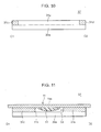
- FIG. 9 is an enlarged sectional view cut along a line B1-B2 showing the movable portion 37 shown in FIG. 7.
- FIG. 10 is an enlarged sectional view cut along a line C1-C2 showing the movable portion 37 shown in FIG. 7.
- FIG. 11 is an enlarged sectional view cut along a line D1-D2 showing the movable portion 37 shown in FIG. 7.
- the supporting members 31 first, second, third, fourth and fifth supporting members 31a, 31b, 31 c, 31d and 31e
- the torsion bar 15 first and second torsion bars 15a, 15b
- the first rib 39a is a part formed to be continuous with the first supporting member 31a and projecting from the supporting body 31 on the other surface 32b of the supporting body 31.
- the second rib 39b is a part formed to be continuous with the second supporting member 31b and projecting from the supporting body 31 on the other surface 32b of the supporting body 31.
- the first rib 39a is provided on the first supporting member 31a, extends in the direction intersecting with the torsion bar 15 and projects on the side of the other surface 32b of the supporting body 31.
- the second rib 39b is provided on the second supporting member 31 b, extends in the direction intersecting with the torsion bar 15 and projects on the side of the other surface 32b of the supporting body 31.
- the supporting body 31 includes a contact surface to be held in contact with the mirror portion 11 and a non-contact surface opposite to the contact surface.
- the first rib 39a is so provided on the first supporting member 31a as to extend in the direction intersecting with the torsion bar 15 and project on the non-contact surface side.
- the second rib 39b is so provided on the second supporting member 31b as to extend in the direction intersecting with the torsion bar 15 and project on the non-contact surface side.
- the first and second supporting members 31a, 31b and the first and second ribs 39a, 39b have the same length. Further, these have the same width. A mass of the first rib 39a and that of the second rib 39b are equal. A total mass of the first and second ribs 39a, 39b is equal to a mass of the mirror portion 11.
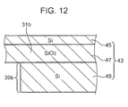
- FIG. 12 is a sectional view enlargedly showing a part indicated by E in FIG. 9.
- An SOI (Silicon on Insulator) substrate 43 is structured such that a silicon oxide film 47 is sandwiched between silicon layers 45 and 49.
- the supporting body 31 and the torsion bar 15 are formed by the silicon layer 45 and the silicon oxide film 47.
- the first and second ribs 39a, 39b are formed by the silicon layer 49.
- the torsion bar 15, the supporting body 31 and the first and second ribs 39a, 39b are formed by selectively etching the SOI substrate 43.
- first and second ribs 39a, 39b may be respectively bonded to the first and second supporting members 31a, 31b by an adhesive or joined thereto by anode junction.
- the first and second ribs 39a, 39b are provided only on the other surface 32b out of the one surface 32a and the other surface 32b of the supporting body 31 and function as reinforcing members for reinforcing the supporting body 31 and adjusting a center of gravity of the movable portion 37 including the torsion bar 15, the supporting body 31 and the mirror portion 11 so that the center of gravity of the movable portion 37 is located on the axis AX.
- the hole portion 53 is provided in the main body portion 311 of the fifth supporting member 31e.
- the supporting body 31 is provided with the hole portion 53.
- the hole portion 53 has a depth in a direction intersecting with the one surface 32a (supporting surface) of the supporting body 31 and located on the axis AX of the torsion bar 15.
- the axis AX passes through the hole portion 53.
- the hole portion 53 penetrates through the supporting body 31 and the surface of the mirror portion 11 (under surface 11b of the mirror portion) opposite to the surface for reflecting light serves as a bottom part of the hole portion 53.
- the mass body 51 is arranged in the hole portion 53.
- the mass body 51 is located on the axis AX of the torsion bar 15.
- the resonant frequency of the movable portion 37 is adjusted by the mass body 51 arranged in the hole portion 53.
- the mass body 51 is a member formed by curing an adhesive fluid. Accordingly, an adhesive, putty or the like can be formed into the mass body 51. In this embodiment, an ultraviolet curing adhesive, which is one of photocurable adhesives, is formed into the mass body 51.
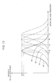
- FIG. 13 is a graph showing a relationship between a frequency of a drive voltage input to the light deflector 10 and the maximum deflection angle of the mirror portion 11.
- a horizontal axis of the graph represents the frequency of the drive voltage and a vertical axis thereof represents the maximum deflection angle.
- a curve (a) represents a case where the mass body 51 is not supplied to the hole portion 53 of the supporting body 31, and fa denotes the resonant frequency in this case.
- a curve (b) represents a case where the mass of the mass body 51 supplied to the hole portion 53 of the supporting body 31 has a first value, and fb denotes the resonant frequency in this case.
- a curve (c) represents a case where the mass of the mass body 51 supplied to the hole portion 53 of the supporting body 31 has a second value larger than the first value, and fc denotes the resonant frequency in this case.
- a curve (d) represents a case where the mass of the mass body 51 supplied to the hole portion 53 of the supporting body 31 has a third value larger than the second value, and fd denotes the resonant frequency in this case.
- the maximum deflection angle at the resonant frequency has the same value ( ⁇ 0).
- the resonant frequency decreases as the mass of the mass body 51 supplied to the hole portion 53 increases (curve (a) ⁇ curve (b) ⁇ curve (c) ⁇ curve (d)).
- the maximum deflection angle can be set at the target value ⁇ 1 at the frequency f1 of the drive voltage.
- FIG. 14 is a block diagram of an adjustment system 61 used in a process of adjusting the resonant frequency in a method for manufacturing the light deflector 10 according to this embodiment.
- the adjustment system 61 includes a light deflector control unit 63, a light source unit 65, a monitor unit 67 and a mass body supply unit 69.
- the light deflector control unit 63 swings the mirror portion 11 about the axis AX of the torsion bar 15 shown in FIG. 4 by inputting a drive voltage to the mirror drivers 17 of the light deflector 10.
- the light source unit 65 includes a laser diode 71 and controls the irradiation of a light beam LB from the laser diode 71 toward the mirror portion 11.
- the monitor unit 67 includes a photodiode 73 and a display unit 75, and computes the maximum deflection angle of the mirror portion 11 and causes the display unit 75 to display a measurement value, utilizing a time interval until the next light reception after the light beam LB reflected by the top surface 11a of the mirror portion 11 is received by the photodiode 73.
- the mass body supply unit 69 includes a nozzle 77 and supplies the mass body 51 to the hole portion 53 (FIG. 8) of the supporting body 31 using the nozzle 77.
- a dispenser for discharging the ultraviolet curing adhesive from the nozzle 77 is used as the mass body supply unit 69.
- FIG. 15 shows a state where the mass body 51 is supplied to the hole portion 53 of the supporting body 31 using the nozzle 77 in the same cross-section as in FIG. 9.
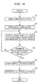
- FIG. 16 is a flow chart showing the process of adjusting the resonant frequency in the method for manufacturing the light deflector 10 according to this embodiment.
- the light deflector control unit 63 swings the mirror portion 11 by inputting a drive voltage having a predetermined voltage value and a frequency f1 to the light deflector 10, i.e. to the mirror drivers 17 in a state where the mass body 51 is not supplied to the hole portion 53 of the supporting body 31 yet (Step S1). Note that if the mirror portion 11 is electromagnetically driven instead of being piezoelectrically driven, the mirror portion 11 is swung by inputting a drive current having a predetermined current value and the frequency f1 to the light deflector 10.
- the light source unit 65 causes a light beam LB to be generated from the laser diode 71 and irradiates the light beam LB to the top surface 11a of the mirror portion 11 in a swinging state (Step S2).
- an adjuster of the resonant frequency operates the mass body supply unit 69 to supply the mass body 51 (ultraviolet curing adhesive) in a fluid state to the hole portion 53 of the supporting body 31 while monitoring the maximum deflection angle (in other words, resonant frequency) displayed on the display unit 75 of the monitor unit 67 (Step S3).
- the adjuster judges whether or not the maximum deflection angle displayed on the display unit 75 has reached the target value ⁇ 1 during Step S3 (Step S4).
- Step S4 If the maximum deflection angle has not reached the target value ⁇ 1 (No in Step S4), a return is made to Step S3.
- Step S4 If the maximum deflection angle reaches the target value ⁇ 1 (Yes in Step S4), the adjuster stops the supply of the mass body 51 to the hole portion 53 of the supporting body 31 from the mass body supply unit 69 (Step S5). Thereafter, the adjuster allows the mass body 51 to be cured by irradiating ultraviolet rays to the mass body 51 supplied to the hole portion 53 of the supporting body 31 using an ultraviolet irradiation device (Step S6).
- the resonant frequency can be finely adjusted in the case of adjusting the resonant frequency of the movable portion 37 of the light deflector 10 while adjusting the mass of the mass body 51, wherefore accuracy in adjusting the resonant frequency can be improved.
- the axis AX of the torsion bar 15 passes through the hole portion 53 in which the mass body 51 is to be arranged.
- the mass body 51 is easily arranged on the axis AX of the torsion bar 15 so as not to deviate from the axis AX of the torsion bar 15.
- a mirror portion is made larger toward both left and right sides, a first area and a second area symmetrical with respect to a torsion bar are respectively provided and a mass body is provided in each area, a lateral dimension of a light deflector becomes larger by the first and second areas. Since the hole portion 53 is arranged on the axis AX of the torsion bar 15 in this embodiment, the lateral dimension of the light deflector 10 does not become larger due to the provision of the hole portion 53.
- the hole portion 53 in which the mass body 51 is to be arranged is located on the axis AX of the torsion bar 15, the hole portion 53 is displaced only to a slight extent even if the mirror portion 11 is swung.
- the mass body 51 in a fluid state can be easily poured into the hole portion 53 while the mirror portion 11 is swung.
- the mass body 51 in the fluid state is supplied to the hole portion 53 (FIG. 15) while the mirror portion 11 is swung and the maximum deflection angle of the mirror portion 11 is monitored.
- a time required for the adjustment of the resonant frequency can be shortened as compared with the case where a step of monitoring the maximum deflection angle of the mirror portion 11 and a step of supplying the mass body 51 in the fluid state to the hole portion 53 are separately performed.
- the mass body 51 is formed in the hole portion 53 by supplying the mass body 51 in the fluid state to the hole portion 53. Thus, particles are not produced, wherefore there is no problem of contaminating or damaging the top surface 11a of the mirror portion 11 due to particles.
- one hole portion 53 is provided and one mass body 51 is arranged in the hole portion 53.
- the adjustment of the resonant frequency can be speeded up as compared with a configuration in which the mass body 51 is arranged in each of a plurality of hole portions 53.
- the first supporting member 31a is fixed to the torsion bar 15a in the center thereof.
- a moment of inertia acting on the first supporting member 31a when the mirror portion 11 is swung about the axis AX of the torsion bar 15 increases with distance from the first torsion bar 15a.
- the second supporting member 31b is fixed to the torsion bar 15b in the center thereof, a moment of inertia acting on the second supporting member 31b when the mirror portion 11 is swung about the axis AX of the torsion bar 15 increases with distance from the second torsion bar 15b.
- the extending directions of the third and fourth supporting members 31c, 31d are the same as that of the torsion bar 15.
- the first and second supporting members 31a, 31b are more easily bended than the third and fourth supporting members 31c, 31d when the mirror portion 11 is swung.
- the supporting body 31 is bended if the first and second supporting members 31a, 31b are bended, with the result that the mirror portion 11 is bended.
- the first rib 39a extending in the direction intersecting with the torsion bar 15 is provided on the first supporting member 31 a extending in the direction intersecting with the torsion bar 15 and the second rib 39b extending in the direction intersecting with the torsion bar 15 is provided on the second supporting member 31b extending in the direction intersecting with the torsion bar 15.
- the bend of the mirror portion 11 when the mirror portion 11 is swung can be suppressed while the supporting body 31 is made lighter.
- the mirror portion 11 is mounted on the third, fourth and fifth supporting members 31c, 31d and 31e without being mounted on the first and second supporting members 31a, 31b.
- first and second supporting members 31a, 31b are bended a little, such bend is not directly transmitted to the mirror portion 11. Therefore, the bend of the mirror portion 11 can be reduced.
- the mirror portion 11 is provided on the one surface 32a of the supporting body 31, the first and second ribs 39a, 39b are provided on the other surface 32b, and the total mass of the first and second ribs 39a, 39b is equal to the mass of the mirror portion 11. Since this makes a mass on the side of the one surface 32a of the supporting body 31 and that on the side of the other surface 32b equal, the center of gravity of the movable portion 37 configured by the torsion bar 15 and the like can be so adjusted as to be located on the axis AX of the torsion bar 15. Therefore, the moment of inertia can be balanced between the side of the one surface 32a of the supporting body 31 and the side of the other surface 32b.
- the center of gravity of the movable portion 37 configured by the mirror portion 11, the supporting body 31, the first rib 39a, the second rib 39b, the first torsion bar 15a and the second torsion bar 15b can be located on the axis AX as center axes of the first and second torsion bars 15a, 15b.
- the mirror portion 11 is swung about the axis AX of the torsion bar 15, movements of the mirror portion 11 other than swinging movements about the axis AX of the torsion bar 15 can be suppressed.
- the same mass mentioned here means that the total mass of the first and second ribs 39a, 39b is completely or substantially equal to the mass of the mirror portion 11.
- To be substantially equal means that a difference between the total mass and the mass of the mirror portion 11 is in a range capable of suppressing movements of the mirror portion 11 other than swinging movements about the axis AX of the torsion bar 15 when the mirror portion 11 is swung about the axis AX of the torsion bar 15.
- the ribs are provided on the other surface 32b of the supporting body 31, but not on the one surface 32a as shown in FIGS. 7 and 8.
- the surfaces of the first, second, third, fourth and fifth supporting members 31a, 31b, 31c, 31d and 31e and the first and second torsion bars 15a, 15b are located on the same plane on the side of the one surface 32a of the supporting body 31.
- the supporting body 31 and the torsion bar 15 are formed by the silicon layer 45 and the silicon oxide film 47 of the SOI substrate 43.
- the first and second ribs 39a, 39b are formed by the silicon layer 49 of the SOI substrate 43.
- the thickness of the first rib 39a and that of the second rib 39b can be set at that of the silicon layer 49, wherefore the accuracy of the thickness of the first rib 39a and that of the second rib 39b (i.e. the accuracy of the total mass of the first and second ribs 39a, 39b) can be enhanced.
- the rigidity of the first torsion bar 15a becomes higher, for example, if the thickness of the first torsion bar 15a is set at a total value of the thickness of the first supporting member 31a and that of the first rib 39a.
- the rigidity of the second torsion bar 15b becomes higher, for example, if the thickness of the second torsion bar 15b is set at a total value of the thickness of the second supporting member 31 b and that of the second rib 39b.
- a swinging angle i.e. the maximum value of the deflection angle ⁇ shown in FIG. 4
- the thickness of the first torsion bar 15a is made smaller than the total value of the thickness of the first supporting member 31 a and that of the first rib 39a
- the thickness of the second torsion bar 15b is made smaller than the total value of the thickness of the second supporting member 31b and that of the second rib 39b. In this way, the swinging angle of the mirror portion 11 is made larger.
Landscapes
- Physics & Mathematics (AREA)
- Engineering & Computer Science (AREA)
- Computer Hardware Design (AREA)
- Microelectronics & Electronic Packaging (AREA)
- General Physics & Mathematics (AREA)
- Optics & Photonics (AREA)
- Micromachines (AREA)
- Mechanical Optical Scanning Systems (AREA)
- Mechanical Light Control Or Optical Switches (AREA)
Abstract

Description
- The present disclosure relates to a light deflector used in forming an electrostatic latent image and the like, a light deflector manufacturing method and an optical scanning device with such a light deflector.
- In an electrophotographic image forming apparatus, a light beam modulated in accordance with image data is generated, reflected and deflected, whereby an image bearing member such as a photoconductive drum is scanned with the deflected light beam to form an electrostatic latent image. The light deflector is a device for reflecting and deflecting a light beam. A technique using MEMS (Micro Electro Mechanical Systems) mirrors as a light deflector instead of a polygon mirror has been proposed. The MEMS mirrors have an advantage of speeded-up scanning, low power consumption and the like.
- The light deflector using the MEMS mirrors includes a torsion bar, mirror portions swingable about an axis of the torsion bar and mirror drivers.
- Upon the input of drive signals to the mirror drivers, the mirror drivers resonate (vibrate) movable portions of the MEMS mirrors to swing the mirror portions about the axis of the torsion bar and, in this state, a light beam incident on the mirror portions is reflected and deflected to scan the light beam. The movable portion of the MEMS mirror is, in other words, a vibration system of the MEMS mirror and configured by the mirror portion and the torsion bar.
- In the case of using the MEMS mirrors by setting the frequencies of the drive signals to be input to the MEMS mirrors at the same value for each MEMS mirror, a resonant frequency of the movable portion of the MEMS mirror (hereinafter, merely referred to as a resonance frequency in some cases) needs to be adjusted for each MEMS mirror. This is because a maximum deflection angle of the mirror portion differs for each MEMS mirror if the resonant frequency differs.
- The resonant frequency is determined by a moment of inertia of the mirror portion, a spring constant of the torsion bar and the like. The resonant frequency changes if these physical quantities only slightly differ. For example, dimensions of the mirror portion affect the moment of inertia of the mirror portion, and the resonant frequency changes if the dimensions of the mirror portion differ from design values by several microns. Since errors in the above physical quantities unavoidably occur in the manufacturing of the MEMS mirror, the resonant frequency needs to be adjusted.
- There have been proposed a technique for adjusting a resonant frequency by reducing a mass of a movable portion of a MEMS mirror and a technique for adjusting a resonant frequency by increasing a mass of a movable portion of the MEMS mirror.
- The former technique adjusts the resonant frequency by providing a first area and a second area, which are symmetrical with respect to a torsion bar, forming a plurality of mass bodies in advance in the respective areas, selectively cutting off the mass body by a laser beam to reduce the mass of the movable portion of the MEMS mirror.
- The latter technique adjusts the resonant frequency by making the mirror portion larger toward both left and right sides, providing a first area and a second area symmetrical with respect to a torsion bar, depositing and curing a liquid in each area to selectively form a mass body and increase the mass of the movable portion of the MEMS mirror.
- A moment of inertia is a value obtained by multiplying a square of a distance between the mass body and the axis of the torsion bar by a mass of the mass body. In the above two techniques, the mass body is located at a distance from the axis of the torsion bar. Thus, a change in the moment of inertia of the mass body (i.e. a change in the moment of inertia of the movable portion of the MEMS mirror) in response to a change in the mass of the mass body becomes relatively large. Therefore, it is disadvantageous in finely adjusting the resonant frequency to adjust the resonant frequency while adjusting the mass of the mass body.
- The present disclosure aims to provide a light deflector capable of improving accuracy in adjusting a resonant frequency of a movable portion of the light deflector, a light deflector manufacturing method and an optical scanning device with such a light deflector.
- A light deflector according to a first aspect of the present disclosure includes a fixing portion and a movable portion. The movable portion includes a mirror portion for deflecting light by swinging about a predetermined swing axis, a torsion bar fixedly supported on the fixing portion and having an axis serving as the swing axis, and a supporting body configured to support the mirror portion and fixed to the torsion bar. The supporting body includes a hole portion through which the axis passes. A mass body for adjusting a resonant frequency of the movable portion is arranged in the hole portion.
- A light deflector manufacturing method according to a second aspect of the present disclosure includes a first step, a second step and a third step. In the first step, the mirror portion is swung by inputting a drive signal to the light deflector in a state where the mass body is not arranged in the hole portion. In the second step, the mass body is supplied in a fluid state to the hole portion during the execution of the first step. In the third step, the supply of the mass body is stopped when the resonant frequency of the movable portion reaches a predetermined value during the execution of the second step.
- An optical scanning device according to a third aspect of the present disclosure includes the above light deflector and a light source for irradiating a light beam to the mirror portion.
- These and other objects, features and advantages of the present disclosure will become more apparent upon reading the following detailed description along with the accompanying drawings.
-
- FIG. 1 is a diagram schematically showing an internal structure of an image forming apparatus to which a light deflector according to an embodiment is applied,
- FIG. 2 is a block diagram showing the configuration of the image forming apparatus shown in FIG. 1,
- FIG. 3 is a diagram showing an arrangement relationship of optical components constituting an optical scanning device provided in the image forming apparatus shown in FIG. 1,
- FIG. 4 is a perspective view of the light deflector according to the embodiment,
- FIG. 5 is a sectional view cut along a line A1-A2 showing the light deflector shown in FIG. 4,
- FIG. 6 is a view showing a state where a PZT thin film of a mirror driver on one side extends and that of a mirror driver on the other side contracts in the same cross-section as in FIG. 5,
- FIG. 7 is a perspective view showing a mirror portion, a torsion bar, a supporting body and a movable portion with a first rib and a second rib provided in the light deflector according to the embodiment when viewed from a top surface (light beam reflecting/deflecting surface) side of the mirror portion,
- FIG. 8 is a perspective view of the movable portion viewed from an under surface side of the mirror portion,
- FIG. 9 is an enlarged sectional view cut along a line B1-B2 showing the movable portion shown in FIG. 7,
- FIG. 10 is an enlarged sectional view cut along a line C1-C2 showing the movable portion shown in FIG. 7,
- FIG. 11 is an enlarged sectional view cut along a line D1-D2 showing the movable portion shown in FIG. 7,
- FIG. 12 is a sectional view enlargedly showing a part indicated by E in FIG. 9,
- FIG. 13 is a graph showing a relationship between a frequency of a drive voltage input to the light deflector and a maximum deflection angle of the mirror portion,
- FIG. 14 is a block diagram of an adjustment system used in a process of adjusting a resonant frequency in a light deflector manufacturing method according to the embodiment,
- FIG. 15 is a view showing a state where a mass body is supplied to a hole portion of the supporting body using a nozzle in the same cross-section as in FIG. 9, and
- FIG. 16 is a flow chart showing the process of adjusting the resonant frequency in the light deflector manufacturing method according to the embodiment.
- Hereinafter, an embodiment of the present disclosure is described based on the drawings. FIG. 1 is a diagram schematically showing an internal structure of an
image forming apparatus 1 to which a light deflector according to the embodiment is applied. Theimage forming apparatus 1 can be, for example, applied to a digital complex machine having copier, printer, scanner and facsimile functions. Theimage forming apparatus 1 includes an apparatusmain body 100, adocument reading unit 200 arranged atop the apparatusmain body 100, adocument feeding unit 300 arranged atop thedocument reading unit 200 and anoperation unit 400 arranged on the front surface of an upper part of the apparatusmain body 100. - The
document feeding unit 300 functions as an automatic document feeder and can successively feed a plurality of documents placed on adocument placing portion 301 to thedocument reading unit 200. - The
document reading unit 200 includes acarriage 201 carrying an exposure lamp and the like, adocument platen 203 made of a transparent material such as glass, an unillustrated CCD (Charge Coupled Device) sensor and adocument reading slit 205. In the case of reading a document placed on thedocument platen 203, the document is read by the CCD sensor while thecarriage 201 is moved in a longitudinal direction of thedocument platen 203. Contrary to this, in the case of reading a document fed from thedocument feeding unit 300, thecarriage 201 is moved to a position facing thedocument reading slit 205 and the document fed from thedocument feeding unit 300 is read by the CCD sensor through thedocument reading slit 205. The CCD sensor outputs an image of the read document as image data. - The apparatus
main body 100 includes asheet storing unit 101, animage forming unit 103 and afixing unit 105. Thesheet storing unit 101 is arranged in a lowest part of the apparatusmain body 100 and includessheet cassettes 107 capable of storing a stack of sheets. The uppermost sheet of the stack of sheets stored in thesheet cassette 107 is fed to asheet conveyance path 111 by driving apickup roller 109. The sheet is conveyed to theimage forming unit 103 through thesheet conveyance path 111. - The
image forming unit 103 forms a toner image on a sheet conveyed thereto. Theimage forming unit 103 includes aphotoconductive drum 113, anoptical scanning device 115, a developingunit 117 and atransfer unit 119. Theoptical scanning device 115 generates light modulated in accordance with image data (image data output from thedocument reading unit 200, image data transmitted from a personal computer, facsimile-received image data or the like) and irradiates the light to the peripheral surface of the uniformly chargedphotoconductive drum 113. This causes an electrostatic latent image corresponding to the image data to be formed on the peripheral surface of thephotoconductive drum 113. In this state, toner is supplied from the developingunit 117 to the peripheral surface of thephotoconductive drum 113, whereby a toner image corresponding to the image data is formed on the peripheral surface. This toner image is transferred to a sheet conveyed from thesheet storing unit 101 described above by thetransfer unit 119. - The sheet having the toner image transferred thereto is conveyed to the fixing
unit 105. In the fixingunit 105, heat and pressure are applied to the toner image and the sheet to fix the toner image to the sheet. The sheet is discharged to astack tray 121 or asheet discharge tray 123. - The
operation unit 400 includes an operationkey unit 401 and adisplay unit 403. Thedisplay unit 403 has a touch panel function and displays a screen including soft keys. A user makes settings necessary to perform a function such as a copy function by operating the soft keys while viewing the screen. - The operation
key unit 401 includes operation keys which are hard keys, specifically astart key 405, anumerical keypad 407, astop key 409, areset key 411,function changeover keys 413 for switching the function among copier, printer, scanner and facsimile functions and the like. - The
start key 405 is a key for starting an operation such as copying or facsimile transmission. Thenumerical keypad 407 is a keypad for entering numbers such as the number of copies and facsimile numbers. Thestop key 409 is a key for stopping a copying operation and the like on the way. Thereset key 411 is a key for returning the set content to an initial setting state. - The
function changeover keys 413 are keys including a copy key, a transmit key and the like and configured to switch a copy function, a transmit function and the like from one to another. If the copy key is operated, an initial screen for copying is displayed on thedisplay unit 403. If the transmit key is operated, an initial screen for facsimile transmission and mail transmission is displayed on thedisplay unit 403. - FIG. 2 is a block diagram showing the configuration of the
image forming apparatus 1 shown in FIG. 1. Theimage forming apparatus 1 is so configured that thedocument reading unit 200, thedocument feeding unit 300, theoperation unit 400, acontrol unit 500 and acommunication unit 600 are connected to each other by a bus. The apparatusmain body 100, thedocument reading unit 200, thedocument feeding unit 300 and theoperation unit 400 are not described since being already described. - The
control unit 500 includes a CPU (Central Processing Unit), a ROM (Read Only Memory), a RAM (Random Access Memory), an image memory and the like. The CPU executes a control necessary to operate theimage forming apparatus 1 on the above constituent elements of theimage forming apparatus 1 such as the apparatusmain body 100. The ROM stores software necessary to control the operation of theimage forming apparatus 1. The RAM is used such as to temporarily store data generated during the execution of the software and store application software. The image memory temporarily stores image data (image data output from thedocument reading unit 200, image data transmitted from a personal computer, facsimile-received image data or the like). - The
communication unit 600 includes afacsimile communication unit 601 and a network I/F unit 603. Thefacsimile communication unit 601 includes an NCU (Network Control Unit) for controlling a telephone line connection with a destination facsimile machine and a modulation/demodulation circuit for modulating/demodulating a signal for facsimile communication. Thefacsimile communication unit 601 is connected to atelephone line 605. - The network I/
F unit 603 is connected to a LAN (Local Area Network) 607. The network I/F unit 603 is a communication interface circuit for carrying out communication with terminal units such as personal computers connected to theLAN 607. - FIG. 3 is a diagram showing an arrangement relationship of optical components constituting the
optical scanning device 115. Theoptical scanning device 115 includes alight source 31, alight deflector 10, twoscanning lenses light source 31 is, for example, a laser diode and emits a light beam LB modulated in accordance with image data. - A
collimator lens 37 and acylindrical lens 39 are arranged on an optical path between thelight source 31 and thelight deflector 10. Thecollimator lens 37 converts the light beam LB emitted from thelight source 31 into a parallel beam. Thecylindrical lens 39 linearly condenses the light beam LB converted into the parallel beam. The linearly condensed light beam LB is incident on thelight deflector 10. - The
scanning lenses light deflector 10 and thephotoconductive drum 113. The light beam LB incident on amirror portion 11 of thelight deflector 10 is reflected and deflected by themirror portion 11 and focused on thephotoconductive drum 113 by thescanning lenses photoconductive drum 113, an electrostatic latent image is formed on thephotoconductive drum 113. - The
optical scanning device 115 further includes aBD lens 41 and aBD sensor 43. The light beam LB is scanned across thephotoconductive drum 113 from onelateral part 113a to anotherlateral part 113b of thephotoconductive drum 113, and the light beam LB beyond an effective scanning range is condensed by theBD lens 41 and received by theBD sensor 43. The BD (Beam Detect)sensor 43 generates a BD signal serving as a reference for the start of scanning (main scanning) on thephotoconductive drum 113. - Next, the
light deflector 10 according to this embodiment is described. FIG. 4 is a perspective view of thelight deflector 10 according to the embodiment, and FIG. 5 is a sectional view cut along a line A1-A2 showing the light deflector shown in FIG. 4. Thelight deflector 10 according to this embodiment is a piezoelectrically driven MEMS mirror. However, the MEMS mirror usable as thelight deflector 10 is not limited to the piezoelectrically driven one. - The
light deflector 10 includes themirror portion 11, aframe 13, atorsion bar 15,mirror drivers body 31. - The
frame 13 has a rectangular shape. Theframe 13 is composed of a pair ofside portions side portions side portions mirror portion 11 is arranged in a central part of theframe 13. Themirror portion 11 has an elliptical shape whose minor axis direction matches the longitudinal direction of theframe 13. - The
torsion bar 15 has an axis AX extending in one direction and serving as a rotation axis (can be also referred to as a torsional rotation axis or a swing axis). Thetorsion bar 15 includes afirst torsion bar 15a and asecond torsion bar 15b extending along the common axis AX. The first andsecond torsion bars mirror portion 11. One end of thefirst torsion bar 15a is fixed and supported by thebeam 19 and one end of thesecond torsion bar 15b is fixed and supported by thebeam 21. - A
space 33 is formed between thebeam 19 and theside portion 13a, and aspace 35 is formed between thebeam 21 and theside portion 13b. - The supporting
body 31 supporting themirror portion 11 is fixed to the other ends of the first andsecond torsion bars body 31 is arranged in theframe 13. The supportingbody 31 has a rectangular shape and a longitudinal direction thereof is perpendicular to that of theframe 13. Thebeams 19, 21 (fixing portion) fix and support thetorsion bar 15 in such a manner that themirror portion 11 supported by the supportingbody 31 is swingable about the axis AX of thetorsion bar 15. - As described above, the
mirror portion 11 deflects light by swinging about a predetermined swing axis, thetorsion bar 15 is fixed and supported by the fixing portion (beams 19, 21) and has the axis AX serving as the swing axis, and the supportingbody 31 supports themirror portion 11 and is fixed to thetorsion bar 15. - On the
beam 19, themirror driver 17a is formed on a side closer to theside portion 13c than thetorsion bar 15 and themirror driver 17b is formed on a side closer to theside portion 13d than thetorsion bar 15. On thebeam 21, themirror driver 17c is formed on a side closer to theside portion 13c than thetorsion bar 15 and themirror driver 17d is formed on a side closer to theside portion 13d than thetorsion bar 15. - As shown in FIG. 5, the
mirror driver 17a is composed of alower electrode 23, a PZTthin film 25 and anupper electrode 27. Themirror drivers mirror driver 17a. Themirror drivers mirror drivers 17 below unless it is necessary to distinguish them. - FIG. 6 is a view showing a state where a drive voltage is applied to the
mirror drivers 17 so that the PZTthin films 25 of themirror drivers mirror drivers beams mirror portion 11 is inclined together with thetorsion bar 15. - The extension of the PZT
thin films 25 of themirror drivers thin films 25 of themirror drivers thin films 25 of themirror drivers thin films 25 of themirror drivers mirror drivers 17 to deflect thebeams mirror portion 11 supported by the supportingbody 31 swings about the axis AX of thetorsion bar 15 to vary a deflection angle θ. Note that NL in FIG. 4 denotes a normal to themirror portion 11 when themirror portion 11 is not swinging. - When a frequency of the drive voltage is caused to match a resonant frequency, the
mirror portion 11 resonates and a maximum value of the deflection angle θ (maximum deflection angle) can be increased. By reflecting and deflecting a light beam by themirror portion 11 in a state where themirror portion 11 is resonated, the light beam is scanned across thephotoconductive drum 113. - FIG. 7 is a perspective view showing the
mirror portion 11, thetorsion bar 15, the supportingbody 31 and amovable portion 37 with afirst rib 39a and asecond rib 39b provided in thelight deflector 10 when viewed from the side of atop surface 11a (light beam reflecting/deflecting surface) of themirror portion 11. FIG. 8 is a perspective view showing thismovable portion 37 viewed from the side of an undersurface 11b of themirror portion 11. - The
top surface 11a of themirror portion 11 is on the side of onesurface 32a (supporting surface) of the supportingbody 31, and theunder surface 11b of themirror portion 11 is supported by the onesurface 32a of the supportingbody 31. - The supporting
body 31 has a rectangular frame-like shape and includes a first supportingmember 31a, a second supportingmember 31 b, a third supportingmember 31c and a fourth supportingmember 31d which serve as four sides forming a rectangle. - The first and second supporting
members torsion bar 15 and are arranged to face each other. - The third and fourth supporting
members torsion bar 15 and are symmetrically arranged with respect to thetorsion bar 15. - A
space 41 is defined by the first, second, third and fourth supportingmembers body 31 is made lighter by providing thespace 41. - As described above, the supporting
body 31 includes the first supportingmember 31 a extending in the direction intersecting with thetorsion bar 15, the second supportingmember 31b arranged to face the first supportingmember 31a and extending in the direction intersecting with thetorsion bar 15, the third supportingmember 31c connecting the first and second supportingmembers member 31d symmetrically arranged to the third supportingmember 31 c with respect to the axis of thetorsion bar 15 and connecting the first and second supportingmembers - The supporting
body 31 further includes a fifth supportingmember 31e arranged in thespace 41. The fifth supportingmember 31e includes amain body portion 311, a first connectingportion 312 and a second connectingportion 313. Themain body portion 311 is a main body of the fifth supportingmember 31e and formed with a circular cavity which functions as ahole portion 53. This makes the supportingbody 31 lighter. - The
mirror portion 11 is a plate-like member including a deflecting surface (top surface 11a) for deflecting light and a non-deflecting surface (undersurface 11b) opposite to the deflecting surface. The non-deflecting surface (undersurface 11b) forms the bottom of thehole portion 53. - The first connecting
portion 312 is arranged on a major axis of themain body portion 311 and connects one end part of themain body portion 311 and a center of the third supportingmember 31c. The second connectingportion 313 is arranged on the major axis of themain body portion 311 and connects the other end part of themain body portion 311 and a center of the fourth supportingmember 31d. - As described above, the
torsion bar 15 is composed of the first andsecond torsion bars second torsion bars body 31 is arranged in an area including this spacing. Thefirst torsion bar 15a is fixed to the first supportingmember 31a in a center of the first supportingmember 31a. Thesecond torsion bar 15b is fixed to the second supportingmember 31 b in a center of the second supportingmember 31b. - As shown in FIG. 7, each of the first, second, third, fourth and fifth supporting
members second torsion bars surface 32a of the supportingbody 31, and each planar portion is located on the same plane. These have the same height (i.e. same thickness). - The
mirror portion 11 is provided on the onesurface 32a of the supportingbody 31. Themirror portion 11 is bonded to the third, fourth and fifth supporting members 3 1 c, 31 d and 31e using an adhesive or joined to the third, fourth and fifth supportingmembers - The first and
second ribs torsion bar 15, are provided on theother surface 32b (opposite surface) of the supportingbody 31. Thefirst rib 39a is provided on the first supportingmember 31a and thesecond rib 39b is provided on the second supportingmember 31b. - The first and
second ribs movable portion 37 shown in FIG. 7. FIG. 10 is an enlarged sectional view cut along a line C1-C2 showing themovable portion 37 shown in FIG. 7. FIG. 11 is an enlarged sectional view cut along a line D1-D2 showing themovable portion 37 shown in FIG. 7. - With reference to FIGS. 7 to 11, the supporting members 31 (first, second, third, fourth and fifth supporting
members second torsion bars first rib 39a is a part formed to be continuous with the first supportingmember 31a and projecting from the supportingbody 31 on theother surface 32b of the supportingbody 31. Thesecond rib 39b is a part formed to be continuous with the second supportingmember 31b and projecting from the supportingbody 31 on theother surface 32b of the supportingbody 31. As just described, thefirst rib 39a is provided on the first supportingmember 31a, extends in the direction intersecting with thetorsion bar 15 and projects on the side of theother surface 32b of the supportingbody 31. Thesecond rib 39b is provided on the second supportingmember 31 b, extends in the direction intersecting with thetorsion bar 15 and projects on the side of theother surface 32b of the supportingbody 31. - In other words, the supporting
body 31 includes a contact surface to be held in contact with themirror portion 11 and a non-contact surface opposite to the contact surface. Thefirst rib 39a is so provided on the first supportingmember 31a as to extend in the direction intersecting with thetorsion bar 15 and project on the non-contact surface side. Thesecond rib 39b is so provided on the second supportingmember 31b as to extend in the direction intersecting with thetorsion bar 15 and project on the non-contact surface side. - The first and second supporting
members second ribs first rib 39a and that of thesecond rib 39b are equal. A total mass of the first andsecond ribs mirror portion 11. - FIG. 12 is a sectional view enlargedly showing a part indicated by E in FIG. 9. An SOI (Silicon on Insulator)
substrate 43 is structured such that asilicon oxide film 47 is sandwiched between silicon layers 45 and 49. The supportingbody 31 and thetorsion bar 15 are formed by thesilicon layer 45 and thesilicon oxide film 47. The first andsecond ribs silicon layer 49. Thetorsion bar 15, the supportingbody 31 and the first andsecond ribs SOI substrate 43. - Note that the first and
second ribs members - The first and
second ribs other surface 32b out of the onesurface 32a and theother surface 32b of the supportingbody 31 and function as reinforcing members for reinforcing the supportingbody 31 and adjusting a center of gravity of themovable portion 37 including thetorsion bar 15, the supportingbody 31 and themirror portion 11 so that the center of gravity of themovable portion 37 is located on the axis AX. - Next, a
mass body 51 is described using FIGS. 8, 9 and 11. As described above, thehole portion 53 is provided in themain body portion 311 of the fifth supportingmember 31e. Specifically, the supportingbody 31 is provided with thehole portion 53. Thehole portion 53 has a depth in a direction intersecting with the onesurface 32a (supporting surface) of the supportingbody 31 and located on the axis AX of thetorsion bar 15. The axis AX passes through thehole portion 53. Thehole portion 53 penetrates through the supportingbody 31 and the surface of the mirror portion 11 (undersurface 11b of the mirror portion) opposite to the surface for reflecting light serves as a bottom part of thehole portion 53. Themass body 51 is arranged in thehole portion 53. Themass body 51 is located on the axis AX of thetorsion bar 15. The resonant frequency of themovable portion 37 is adjusted by themass body 51 arranged in thehole portion 53. - The
mass body 51 is a member formed by curing an adhesive fluid. Accordingly, an adhesive, putty or the like can be formed into themass body 51. In this embodiment, an ultraviolet curing adhesive, which is one of photocurable adhesives, is formed into themass body 51. - An adjustment of the resonant frequency using the mass body is described. FIG. 13 is a graph showing a relationship between a frequency of a drive voltage input to the
light deflector 10 and the maximum deflection angle of themirror portion 11. A horizontal axis of the graph represents the frequency of the drive voltage and a vertical axis thereof represents the maximum deflection angle. - A curve (a) represents a case where the
mass body 51 is not supplied to thehole portion 53 of the supportingbody 31, and fa denotes the resonant frequency in this case. A curve (b) represents a case where the mass of themass body 51 supplied to thehole portion 53 of the supportingbody 31 has a first value, and fb denotes the resonant frequency in this case. A curve (c) represents a case where the mass of themass body 51 supplied to thehole portion 53 of the supportingbody 31 has a second value larger than the first value, and fc denotes the resonant frequency in this case. A curve (d) represents a case where the mass of themass body 51 supplied to thehole portion 53 of the supportingbody 31 has a third value larger than the second value, and fd denotes the resonant frequency in this case. An example of using thelight deflector 10 with the frequency of the drive voltage input to thelight deflector 10 set at f1 and a target value of the maximum deflection angle set at θ1 is described. - In the respective cases of the curves (a) to (d), the maximum deflection angle at the resonant frequency has the same value (θ0). The resonant frequency decreases as the mass of the
mass body 51 supplied to thehole portion 53 increases (curve (a)→curve (b)→curve (c)→curve (d)). Thus, by adjusting the mass of themass body 51 supplied to thehole portion 53 to adjust the resonant frequency in a state where the frequency of the drive voltage is f1, the maximum deflection angle can be set at the target value θ1 at the frequency f1 of the drive voltage. - FIG. 14 is a block diagram of an
adjustment system 61 used in a process of adjusting the resonant frequency in a method for manufacturing thelight deflector 10 according to this embodiment. Theadjustment system 61 includes a lightdeflector control unit 63, alight source unit 65, amonitor unit 67 and a massbody supply unit 69. - The light
deflector control unit 63 swings themirror portion 11 about the axis AX of thetorsion bar 15 shown in FIG. 4 by inputting a drive voltage to themirror drivers 17 of thelight deflector 10. - The
light source unit 65 includes alaser diode 71 and controls the irradiation of a light beam LB from thelaser diode 71 toward themirror portion 11. - The
monitor unit 67 includes aphotodiode 73 and adisplay unit 75, and computes the maximum deflection angle of themirror portion 11 and causes thedisplay unit 75 to display a measurement value, utilizing a time interval until the next light reception after the light beam LB reflected by thetop surface 11a of themirror portion 11 is received by thephotodiode 73. - The mass
body supply unit 69 includes anozzle 77 and supplies themass body 51 to the hole portion 53 (FIG. 8) of the supportingbody 31 using thenozzle 77. In this embodiment, a dispenser for discharging the ultraviolet curing adhesive from thenozzle 77 is used as the massbody supply unit 69. FIG. 15 shows a state where themass body 51 is supplied to thehole portion 53 of the supportingbody 31 using thenozzle 77 in the same cross-section as in FIG. 9. - FIG. 16 is a flow chart showing the process of adjusting the resonant frequency in the method for manufacturing the
light deflector 10 according to this embodiment. - The light
deflector control unit 63 swings themirror portion 11 by inputting a drive voltage having a predetermined voltage value and a frequency f1 to thelight deflector 10, i.e. to themirror drivers 17 in a state where themass body 51 is not supplied to thehole portion 53 of the supportingbody 31 yet (Step S1). Note that if themirror portion 11 is electromagnetically driven instead of being piezoelectrically driven, themirror portion 11 is swung by inputting a drive current having a predetermined current value and the frequency f1 to thelight deflector 10. - The
light source unit 65 causes a light beam LB to be generated from thelaser diode 71 and irradiates the light beam LB to thetop surface 11a of themirror portion 11 in a swinging state (Step S2). - In a state of Step S2, an adjuster of the resonant frequency operates the mass
body supply unit 69 to supply the mass body 51 (ultraviolet curing adhesive) in a fluid state to thehole portion 53 of the supportingbody 31 while monitoring the maximum deflection angle (in other words, resonant frequency) displayed on thedisplay unit 75 of the monitor unit 67 (Step S3). - The adjuster judges whether or not the maximum deflection angle displayed on the
display unit 75 has reached the target value θ1 during Step S3 (Step S4). - If the maximum deflection angle has not reached the target value θ1 (No in Step S4), a return is made to Step S3.
- If the maximum deflection angle reaches the target value θ1 (Yes in Step S4), the adjuster stops the supply of the
mass body 51 to thehole portion 53 of the supportingbody 31 from the mass body supply unit 69 (Step S5). Thereafter, the adjuster allows themass body 51 to be cured by irradiating ultraviolet rays to themass body 51 supplied to thehole portion 53 of the supportingbody 31 using an ultraviolet irradiation device (Step S6). - By the above, it is possible to obtain the
light deflector 10 in which the maximum deflection angle of themirror portion 11 reaches the target value θ1 when the drive voltage has the frequency f1. - Main effects of this embodiment are described. According to this embodiment, since the axis AX of the
torsion bar 15 passes through thehole portion 53 in which themass body 51 is to be arranged as shown in FIG. 8, themass body 51 can be arranged on the axis AX of thetorsion bar 15. Thus, a change in the moment of inertia of the mass body 51 (i.e. a change in the moment of inertia of themovable portion 37 of the light deflector 10) in response to a change in the mass of themass body 51 becomes relatively small. Thus, the resonant frequency can be finely adjusted in the case of adjusting the resonant frequency of themovable portion 37 of thelight deflector 10 while adjusting the mass of themass body 51, wherefore accuracy in adjusting the resonant frequency can be improved. - Further, according to this embodiment, the axis AX of the
torsion bar 15 passes through thehole portion 53 in which themass body 51 is to be arranged. Thus, as compared with the case where thehole portion 53 is not provided, themass body 51 is easily arranged on the axis AX of thetorsion bar 15 so as not to deviate from the axis AX of thetorsion bar 15. - As described in the description of the background art, if a mirror portion is made larger toward both left and right sides, a first area and a second area symmetrical with respect to a torsion bar are respectively provided and a mass body is provided in each area, a lateral dimension of a light deflector becomes larger by the first and second areas. Since the
hole portion 53 is arranged on the axis AX of thetorsion bar 15 in this embodiment, the lateral dimension of thelight deflector 10 does not become larger due to the provision of thehole portion 53. - Since the
hole portion 53 in which themass body 51 is to be arranged is located on the axis AX of thetorsion bar 15, thehole portion 53 is displaced only to a slight extent even if themirror portion 11 is swung. Thus, themass body 51 in a fluid state can be easily poured into thehole portion 53 while themirror portion 11 is swung. As shown in FIG. 14, according to this embodiment, themass body 51 in the fluid state is supplied to the hole portion 53 (FIG. 15) while themirror portion 11 is swung and the maximum deflection angle of themirror portion 11 is monitored. Thus, a time required for the adjustment of the resonant frequency can be shortened as compared with the case where a step of monitoring the maximum deflection angle of themirror portion 11 and a step of supplying themass body 51 in the fluid state to thehole portion 53 are separately performed. - In the case of adjusting the resonant frequency by forming the mass body in the supporting
body 31 in advance and cutting the mass body by a laser beam or the like, particles are unavoidably produced and may contaminate or damage thetop surface 11a (surface for reflecting light) of themirror portion 11. In this embodiment, themass body 51 is formed in thehole portion 53 by supplying themass body 51 in the fluid state to thehole portion 53. Thus, particles are not produced, wherefore there is no problem of contaminating or damaging thetop surface 11a of themirror portion 11 due to particles. - According to this embodiment, one
hole portion 53 is provided and onemass body 51 is arranged in thehole portion 53. Thus, the adjustment of the resonant frequency can be speeded up as compared with a configuration in which themass body 51 is arranged in each of a plurality ofhole portions 53. - With reference to FIGS. 7 and 8, the first supporting
member 31a is fixed to thetorsion bar 15a in the center thereof. Thus, a moment of inertia acting on the first supportingmember 31a when themirror portion 11 is swung about the axis AX of thetorsion bar 15 increases with distance from thefirst torsion bar 15a. Similarly, since the second supportingmember 31b is fixed to thetorsion bar 15b in the center thereof, a moment of inertia acting on the second supportingmember 31b when themirror portion 11 is swung about the axis AX of thetorsion bar 15 increases with distance from thesecond torsion bar 15b. - Contrary to this, the extending directions of the third and fourth supporting
members torsion bar 15. Thus, the first and second supportingmembers members mirror portion 11 is swung. The supportingbody 31 is bended if the first and second supportingmembers mirror portion 11 is bended. - If ribs are provided on all the first, second, third and fourth supporting
members mirror portion 11, a mass of the supportingbody 31 increases. - Accordingly, in this embodiment, the
first rib 39a extending in the direction intersecting with thetorsion bar 15 is provided on the first supportingmember 31 a extending in the direction intersecting with thetorsion bar 15 and thesecond rib 39b extending in the direction intersecting with thetorsion bar 15 is provided on the second supportingmember 31b extending in the direction intersecting with thetorsion bar 15. - By the above, according to this embodiment, the bend of the
mirror portion 11 when themirror portion 11 is swung can be suppressed while the supportingbody 31 is made lighter. - The
mirror portion 11 is mounted on the third, fourth and fifth supportingmembers members members mirror portion 11. Therefore, the bend of themirror portion 11 can be reduced. - According to this embodiment, the
mirror portion 11 is provided on the onesurface 32a of the supportingbody 31, the first andsecond ribs other surface 32b, and the total mass of the first andsecond ribs mirror portion 11. Since this makes a mass on the side of the onesurface 32a of the supportingbody 31 and that on the side of theother surface 32b equal, the center of gravity of themovable portion 37 configured by thetorsion bar 15 and the like can be so adjusted as to be located on the axis AX of thetorsion bar 15. Therefore, the moment of inertia can be balanced between the side of the onesurface 32a of the supportingbody 31 and the side of theother surface 32b. - Specifically, as shown in FIG. 9, the center of gravity of the
movable portion 37 configured by themirror portion 11, the supportingbody 31, thefirst rib 39a, thesecond rib 39b, thefirst torsion bar 15a and thesecond torsion bar 15b can be located on the axis AX as center axes of the first andsecond torsion bars mirror portion 11 is swung about the axis AX of thetorsion bar 15, movements of themirror portion 11 other than swinging movements about the axis AX of thetorsion bar 15 can be suppressed. - The same mass mentioned here means that the total mass of the first and
second ribs mirror portion 11. To be substantially equal means that a difference between the total mass and the mass of themirror portion 11 is in a range capable of suppressing movements of themirror portion 11 other than swinging movements about the axis AX of thetorsion bar 15 when themirror portion 11 is swung about the axis AX of thetorsion bar 15. - Further, according to this embodiment, the ribs (
first rib 39a,second rib 39b) are provided on theother surface 32b of the supportingbody 31, but not on the onesurface 32a as shown in FIGS. 7 and 8. As shown in FIGS. 7 and 8, the surfaces of the first, second, third, fourth and fifth supportingmembers second torsion bars surface 32a of the supportingbody 31. Thus, it is not necessary to etch both surfaces of theSOI substrate 43 and ribs can be formed by selectively etching one surface, wherefore the number of manufacturing steps of thelight deflector 10 can be reduced. Hence, the cost of thelight deflector 10 can be reduced. - As shown in FIG. 12, the supporting
body 31 and thetorsion bar 15 are formed by thesilicon layer 45 and thesilicon oxide film 47 of theSOI substrate 43. The first andsecond ribs silicon layer 49 of theSOI substrate 43. Thus, the thickness of thefirst rib 39a and that of thesecond rib 39b can be set at that of thesilicon layer 49, wherefore the accuracy of the thickness of thefirst rib 39a and that of thesecond rib 39b (i.e. the accuracy of the total mass of the first andsecond ribs - With reference to FIG. 9, the rigidity of the
first torsion bar 15a becomes higher, for example, if the thickness of thefirst torsion bar 15a is set at a total value of the thickness of the first supportingmember 31a and that of thefirst rib 39a. Similarly, the rigidity of thesecond torsion bar 15b becomes higher, for example, if the thickness of thesecond torsion bar 15b is set at a total value of the thickness of the second supportingmember 31 b and that of thesecond rib 39b. In this way, a swinging angle (i.e. the maximum value of the deflection angle θ shown in FIG. 4) of themirror portion 11 becomes smaller. - Accordingly, in this embodiment, the thickness of the
first torsion bar 15a is made smaller than the total value of the thickness of the first supportingmember 31 a and that of thefirst rib 39a, and the thickness of thesecond torsion bar 15b is made smaller than the total value of the thickness of the second supportingmember 31b and that of thesecond rib 39b. In this way, the swinging angle of themirror portion 11 is made larger. - Although the present disclosure has been fully described by way of example with reference to the accompanying drawings, it is to be understood that various changes and modifications will be apparent to those skilled in the art. Therefore, unless otherwise such changes and modifications depart from the scope of the present disclosure hereinafter defined, they should be construed as being included therein.
Claims (12)
- A light deflector (10), comprising:a fixing portion (19, 21); anda movable portion (37) including a mirror portion (11) for deflecting light by swinging about a predetermined swing axis (AX), a torsion bar (15) fixedly supported on the fixing portion and having an axis serving as the swing axis, and a supporting body (31) configured to support the mirror portion and fixed to the torsion bar;wherein:the supporting body includes a hole portion (53) through which the axis passes; anda mass body (51) for adjusting a resonant frequency of the movable portion is arranged in the hole portion.
- A light deflector according to claim 1, wherein:one hole portion is provided and one mass body is arranged in the hole portion.
- A light deflector according to claim 1 or 2, wherein:the mirror portion is a plate-like member including a deflecting surface (11a) for deflecting light and a non-deflecting surface (11b) opposite to the deflecting surface;the hole portion passes through the supporting body; andthe non-deflecting surface of the mirror portion forms a bottom of the hole portion.
- A light deflector according to any one of claims 1 to 3, wherein:the supporting body includes a first supporting member (31a) extending in a direction intersecting with the torsion bar, a second supporting member (31 b) arranged to face the first supporting member and extending in a direction intersecting with the torsion bar, a third supporting member (31c) connecting the first and second supporting members, a fourth supporting member (31d) arranged symmetrically to the third supporting member with respect to the torsion bar and connecting the first and second supporting members, a fifth supporting member (31e) including the hole portion, and a space (41) defined by the first, second, third and fourth supporting members and having the fifth supporting member arranged therein; andthe torsion bar includes a first torsion bar (15a) fixed to the first supporting member in a center of the first supporting member and a second torsion bar (15b) fixed to the_second supporting member in a center of the second supporting member.
- A light deflector according to claim 4, further composing a first rib (39a) and a second rib (39b) for reinforcing the supporting body, wherein:the supporting body includes a contact surface (32a) to be held in contact with the mirror portion and a non-contact surface (32b) opposite to the contact surface;the first rib extends in a direction intersecting with the torsion bar and is provided on the first supporting member to project on the non-contact surface side; andthe second rib extends in a direction intersecting with the torsion bar and is provided on the second supporting member to project on the non-contact surface side.
- A light deflector according to claim 5, wherein:a total mass of the first and second ribs is equal to a mass of the mirror portion.
- A light deflector according to claim 5 or 6, wherein:the supporting body, the first torsion bar, the second torsion bar, the first rib and the second rib are formed by processing a substrate (43) including a first silicon layer (45), a second silicon layer (49), and a silicon oxide film (47) sandwiched between the first and second silicon layers;the supporting body, the first torsion bar and the second torsion bar are formed by the first silicon layer and the silicon oxide film; andthe first and second ribs are formed by the second silicon layer.
- A light deflector according to any one of claims 1 to 7, further comprising a mirror driver (17) for generating a drive force for swinging the mirror portion supported by the supporting body about the axis of the torsion bar using a piezoelectric element.
- A light deflector according to any one of claims 1 to 8, wherein:the mass body is a member formed by curing an adhesive fluid.
- A method for manufacturing a light deflector according to claim 9, compressing:a first step of swinging the mirror portion by inputting a drive signal to the light deflector in a state where the mass body is not arranged in the hole portion;a second step of supplying the mass body in a fluid state to the hole portion during the execution of the first step; anda third step of stopping the supply of the mass body when the resonant frequency of the movable portion reaches a predetermined value during the execution of the second step.
- A method for manufacturing a light deflector according to claim 10, wherein:a frequency of the drive signal is a predetermined frequency in the first step;the mass body in the fluid state is supplied to the hole portion in the second step while a maximum deflection angle of the mirror portion is monitored; andthe supply of the mass body is stopped in the third step when the maximum deflection angle of the mirror portion reaches the predetermined value during the execution of the second step.
- An optical scanning device (115), comprising:a light deflector according to any one of claims 1 to 9; anda light source (31) for irradiating a light beam to the mirror portion.
Applications Claiming Priority (1)
| Application Number | Priority Date | Filing Date | Title |
|---|---|---|---|
| JP2013115463A JP5873836B2 (en) | 2013-05-31 | 2013-05-31 | Optical deflector, manufacturing method thereof, and optical scanning device |
Publications (3)
| Publication Number | Publication Date |
|---|---|
| EP2808296A2 true EP2808296A2 (en) | 2014-12-03 |
| EP2808296A3 EP2808296A3 (en) | 2015-03-04 |
| EP2808296B1 EP2808296B1 (en) | 2016-01-06 |
Family
ID=50846744
Family Applications (1)
| Application Number | Title | Priority Date | Filing Date |
|---|---|---|---|
| EP14001863.1A Not-in-force EP2808296B1 (en) | 2013-05-31 | 2014-05-28 | Light deflector, light deflector manufacturing method and optical scanning device |
Country Status (4)
| Country | Link |
|---|---|
| US (1) | US9594244B2 (en) |
| EP (1) | EP2808296B1 (en) |
| JP (1) | JP5873836B2 (en) |
| CN (2) | CN104216108B (en) |
Cited By (1)
| Publication number | Priority date | Publication date | Assignee | Title |
|---|---|---|---|---|
| IT201700043616A1 (en) * | 2017-04-20 | 2018-10-20 | St Microelectronics Srl | OSCILLATING STRUCTURE WITH REDUCED DYNAMIC DEFORMATION, OPTICAL DEVICE INCLUDING THE OSCILLATING STRUCTURE, AND METHOD OF MANUFACTURING THE OSCILLATING STRUCTURE |
Families Citing this family (5)
| Publication number | Priority date | Publication date | Assignee | Title |
|---|---|---|---|---|
| US20070244968A1 (en) * | 2006-04-18 | 2007-10-18 | Sony Ericsson Mobile Communications Ab | Method and arrangement in a communications network |
| JP6384676B2 (en) * | 2015-11-27 | 2018-09-05 | 京セラドキュメントソリューションズ株式会社 | Optical deflector and image forming apparatus provided with the optical deflector |
| JP6809018B2 (en) * | 2016-07-26 | 2021-01-06 | 株式会社リコー | Light deflector, light scanning device, image forming device and image projection device |
| JP7089157B2 (en) * | 2018-03-02 | 2022-06-22 | ミツミ電機株式会社 | Actuator and optical scanning device |
| US11662570B2 (en) | 2020-06-17 | 2023-05-30 | Infineon Technologies Ag | Mems scanner suspension system enabling high frequency and high mechanical tilt angle for large mirrors |
Family Cites Families (27)
| Publication number | Priority date | Publication date | Assignee | Title |
|---|---|---|---|---|
| JPH0792409A (en) * | 1993-09-27 | 1995-04-07 | Canon Inc | Optical scanner |
| KR100446624B1 (en) * | 2002-02-27 | 2004-09-04 | 삼성전자주식회사 | Anodic bonding structure and fabricating method thereof |
| US6894823B2 (en) * | 2002-04-26 | 2005-05-17 | Corning Intellisense Llc | Magnetically actuated microelectromechanical devices and method of manufacture |
| DE10221799A1 (en) * | 2002-05-15 | 2003-11-27 | Fujitsu Ltd | Semiconductor sensor for detecting target molecules and molecular change effects in protein recognition, analysis and quantification comprises a field effect transistor with a gate produced from SOI substrates |
| JP3862623B2 (en) * | 2002-07-05 | 2006-12-27 | キヤノン株式会社 | Optical deflector and manufacturing method thereof |
| US7259900B2 (en) * | 2002-11-08 | 2007-08-21 | Texas Instruments Incorporated | Multilayer torsional hinged mirror with a recessed drive/sensing permanent magnet |
| JP4409894B2 (en) * | 2003-09-16 | 2010-02-03 | 株式会社リコー | Optical scanning device, optical writing device, and image forming apparatus |
| US7485485B2 (en) * | 2004-02-09 | 2009-02-03 | Microvision, Inc. | Method and apparatus for making a MEMS scanner |
| JP4641378B2 (en) * | 2004-02-16 | 2011-03-02 | キヤノン株式会社 | Optical scanning device and image display device having the same |
| JP4562462B2 (en) * | 2004-08-31 | 2010-10-13 | 日本信号株式会社 | Planar actuator |
| JP2006239842A (en) * | 2005-03-04 | 2006-09-14 | Seiko Epson Corp | Method for adjusting resonance frequency of actuator and actuator |
| US20070064293A1 (en) * | 2005-09-16 | 2007-03-22 | Texas Instruments Incorporated | Method of adjusting the resonant frequency of an assembled torsional hinged device |
| US7557972B2 (en) | 2006-06-07 | 2009-07-07 | Canon Kabushiki Kaisha | Oscillator device, optical deflector and optical instrument using the same |
| US8284165B2 (en) | 2006-10-13 | 2012-10-09 | Sony Corporation | Information display apparatus with proximity detection performance and information display method using the same |
| TW201002607A (en) * | 2008-07-02 | 2010-01-16 | Touch Micro System Tech | Method of modulating resonant frequency of torsional MEMS device |
| CN101618848B (en) * | 2008-07-04 | 2012-04-11 | 探微科技股份有限公司 | Torsion MEMS |
| JP5146204B2 (en) * | 2008-08-29 | 2013-02-20 | セイコーエプソン株式会社 | Optical device, optical scanner, and image forming apparatus |
| JP5168659B2 (en) * | 2008-11-27 | 2013-03-21 | 株式会社リコー | Movable plate structure and optical scanning device |
| JP5493735B2 (en) * | 2009-01-30 | 2014-05-14 | 株式会社リコー | Deflection mirror, optical scanning device, image forming device, and image projection device |
| DE102009026507A1 (en) | 2009-05-27 | 2010-12-02 | Robert Bosch Gmbh | Micromechanical component and production method for a micromechanical component |
| JP5257397B2 (en) * | 2010-03-31 | 2013-08-07 | ブラザー工業株式会社 | Manufacturing method of optical scanning device |
| WO2011152215A1 (en) * | 2010-06-02 | 2011-12-08 | 日本電気株式会社 | Optical scanning element and image display device equipped with same |
| JP2012032678A (en) * | 2010-08-02 | 2012-02-16 | Funai Electric Co Ltd | Oscillation mirror element, and method of manufacturing oscillation mirror element |
| JP2012083436A (en) * | 2010-10-07 | 2012-04-26 | Brother Ind Ltd | Optical scanner, image forming apparatus with the optical scanner, and method for manufacturing optical scanner |
| JP5736766B2 (en) | 2010-12-22 | 2015-06-17 | ミツミ電機株式会社 | Optical scanning device |
| JP5842369B2 (en) * | 2011-04-11 | 2016-01-13 | セイコーエプソン株式会社 | Actuator manufacturing method, optical scanner manufacturing method and image forming apparatus manufacturing method, actuator, optical scanner and image forming apparatus |
| JP2012242595A (en) * | 2011-05-19 | 2012-12-10 | Nec Corp | Optical scanner and image display apparatus |
-
2013
- 2013-05-31 JP JP2013115463A patent/JP5873836B2/en not_active Expired - Fee Related
-
2014
- 2014-05-28 CN CN201410230681.0A patent/CN104216108B/en not_active Expired - Fee Related
- 2014-05-28 CN CN201710130500.0A patent/CN107055453A/en active Pending
- 2014-05-28 EP EP14001863.1A patent/EP2808296B1/en not_active Not-in-force
- 2014-05-29 US US14/289,807 patent/US9594244B2/en not_active Expired - Fee Related
Non-Patent Citations (1)
| Title |
|---|
| None |
Cited By (3)
| Publication number | Priority date | Publication date | Assignee | Title |
|---|---|---|---|---|
| IT201700043616A1 (en) * | 2017-04-20 | 2018-10-20 | St Microelectronics Srl | OSCILLATING STRUCTURE WITH REDUCED DYNAMIC DEFORMATION, OPTICAL DEVICE INCLUDING THE OSCILLATING STRUCTURE, AND METHOD OF MANUFACTURING THE OSCILLATING STRUCTURE |
| EP3392696A1 (en) * | 2017-04-20 | 2018-10-24 | STMicroelectronics S.r.l. | Oscillating structure with reduced dynamic deformation, optical device including the oscillating structure, and method of manufacturing the oscillating structure |
| US10914938B2 (en) | 2017-04-20 | 2021-02-09 | Stmicroelectronics S.R.L. | Oscillating structure with reduced dynamic deformation, optical device including the oscillating structure, and method of manufacturing the oscillating structure |
Also Published As
| Publication number | Publication date |
|---|---|
| JP2014235244A (en) | 2014-12-15 |
| US20140355090A1 (en) | 2014-12-04 |
| CN104216108A (en) | 2014-12-17 |
| EP2808296A3 (en) | 2015-03-04 |
| US9594244B2 (en) | 2017-03-14 |
| CN104216108B (en) | 2017-05-24 |
| JP5873836B2 (en) | 2016-03-01 |
| EP2808296B1 (en) | 2016-01-06 |
| CN107055453A (en) | 2017-08-18 |
Similar Documents
| Publication | Publication Date | Title |
|---|---|---|
| US9279981B2 (en) | Light deflector, optical scanning device and image forming apparatus | |
| EP2808296B1 (en) | Light deflector, light deflector manufacturing method and optical scanning device | |
| US6972883B2 (en) | Vibration mirror, optical scanning device, and image forming using the same, method for making the same, and method for scanning image | |
| JP2007199682A (en) | Optical deflector and light beam scanning apparatus | |
| JP2008216911A (en) | Optical scanning device and image forming device | |
| JP5041835B2 (en) | Optical scanning apparatus and image forming apparatus | |
| JP5447783B2 (en) | Optical scanning device and image forming apparatus provided with the optical scanning device | |
| JP6384676B2 (en) | Optical deflector and image forming apparatus provided with the optical deflector | |
| JP2010204142A (en) | Optical deflector, optical scanner and image forming apparatus | |
| JP5240472B2 (en) | Light source unit, optical scanning device, and image forming apparatus | |
| US8174554B2 (en) | Optical scanning device and printing apparatus using a threshold matrix to improve image quality | |
| JP2021179458A (en) | Optical scanner and image forming apparatus including the same | |
| JP2012118245A (en) | Optical scanner and image forming apparatus | |
| JP5879175B2 (en) | Image forming apparatus | |
| JP6071914B2 (en) | Optical scanning device and image forming apparatus | |
| JP6062896B2 (en) | Optical scanning device | |
| JP5505590B2 (en) | Optical scanning apparatus and image forming apparatus | |
| JP5806964B2 (en) | Optical scanning apparatus and image forming apparatus | |
| JP5470347B2 (en) | Optical scanning device and image forming apparatus using the same | |
| JP2007025009A (en) | Optical scanner unit and image forming apparatus equipped therewith | |
| JP2008076449A (en) | Optical scanning apparatus and image forming apparatus | |
| JP6016645B2 (en) | Optical scanning device and image forming apparatus having the same | |
| JP4974839B2 (en) | Optical deflection apparatus and image forming apparatus | |
| JP2015219353A (en) | Optical scanning device and image forming apparatus with the same | |
| JP2008009188A (en) | Optical scanner and image forming apparatus |
Legal Events
| Date | Code | Title | Description |
|---|---|---|---|
| PUAI | Public reference made under article 153(3) epc to a published international application that has entered the european phase |
Free format text: ORIGINAL CODE: 0009012 |
|
| 17P | Request for examination filed |
Effective date: 20140528 |
|
| AK | Designated contracting states |
Kind code of ref document: A2 Designated state(s): AL AT BE BG CH CY CZ DE DK EE ES FI FR GB GR HR HU IE IS IT LI LT LU LV MC MK MT NL NO PL PT RO RS SE SI SK SM TR |
|
| AX | Request for extension of the european patent |
Extension state: BA ME |
|
| PUAL | Search report despatched |
Free format text: ORIGINAL CODE: 0009013 |
|
| AK | Designated contracting states |
Kind code of ref document: A3 Designated state(s): AL AT BE BG CH CY CZ DE DK EE ES FI FR GB GR HR HU IE IS IT LI LT LU LV MC MK MT NL NO PL PT RO RS SE SI SK SM TR |
|
| AX | Request for extension of the european patent |
Extension state: BA ME |
|
| RIC1 | Information provided on ipc code assigned before grant |
Ipc: B81B 3/00 20060101AFI20150126BHEP |
|
| R17P | Request for examination filed (corrected) |
Effective date: 20150416 |
|
| RBV | Designated contracting states (corrected) |
Designated state(s): AL AT BE BG CH CY CZ DE DK EE ES FI FR GB GR HR HU IE IS IT LI LT LU LV MC MK MT NL NO PL PT RO RS SE SI SK SM TR |
|
| GRAP | Despatch of communication of intention to grant a patent |
Free format text: ORIGINAL CODE: EPIDOSNIGR1 |
|
| GRAJ | Information related to disapproval of communication of intention to grant by the applicant or resumption of examination proceedings by the epo deleted |
Free format text: ORIGINAL CODE: EPIDOSDIGR1 |
|
| GRAP | Despatch of communication of intention to grant a patent |
Free format text: ORIGINAL CODE: EPIDOSNIGR1 |
|
| INTG | Intention to grant announced |
Effective date: 20150701 |
|
| INTG | Intention to grant announced |
Effective date: 20150715 |
|
| GRAS | Grant fee paid |
Free format text: ORIGINAL CODE: EPIDOSNIGR3 |
|
| GRAA | (expected) grant |
Free format text: ORIGINAL CODE: 0009210 |
|
| AK | Designated contracting states |
Kind code of ref document: B1 Designated state(s): AL AT BE BG CH CY CZ DE DK EE ES FI FR GB GR HR HU IE IS IT LI LT LU LV MC MK MT NL NO PL PT RO RS SE SI SK SM TR |
|
| REG | Reference to a national code |
Ref country code: GB Ref legal event code: FG4D |
|
| REG | Reference to a national code |
Ref country code: CH Ref legal event code: EP |
|
| REG | Reference to a national code |
Ref country code: IE Ref legal event code: FG4D |
|
| REG | Reference to a national code |
Ref country code: AT Ref legal event code: REF Ref document number: 768677 Country of ref document: AT Kind code of ref document: T Effective date: 20160215 |
|
| REG | Reference to a national code |
Ref country code: DE Ref legal event code: R096 Ref document number: 602014000656 Country of ref document: DE |
|
| REG | Reference to a national code |
Ref country code: FR Ref legal event code: PLFP Year of fee payment: 3 |
|
| REG | Reference to a national code |
Ref country code: LT Ref legal event code: MG4D |
|
| REG | Reference to a national code |
Ref country code: NL Ref legal event code: MP Effective date: 20160106 |
|
| REG | Reference to a national code |
Ref country code: AT Ref legal event code: MK05 Ref document number: 768677 Country of ref document: AT Kind code of ref document: T Effective date: 20160106 |
|
| PG25 | Lapsed in a contracting state [announced via postgrant information from national office to epo] |
Ref country code: NL Free format text: LAPSE BECAUSE OF FAILURE TO SUBMIT A TRANSLATION OF THE DESCRIPTION OR TO PAY THE FEE WITHIN THE PRESCRIBED TIME-LIMIT Effective date: 20160106 |
|
| PG25 | Lapsed in a contracting state [announced via postgrant information from national office to epo] |
Ref country code: HR Free format text: LAPSE BECAUSE OF FAILURE TO SUBMIT A TRANSLATION OF THE DESCRIPTION OR TO PAY THE FEE WITHIN THE PRESCRIBED TIME-LIMIT Effective date: 20160106 Ref country code: ES Free format text: LAPSE BECAUSE OF FAILURE TO SUBMIT A TRANSLATION OF THE DESCRIPTION OR TO PAY THE FEE WITHIN THE PRESCRIBED TIME-LIMIT Effective date: 20160106 Ref country code: GR Free format text: LAPSE BECAUSE OF FAILURE TO SUBMIT A TRANSLATION OF THE DESCRIPTION OR TO PAY THE FEE WITHIN THE PRESCRIBED TIME-LIMIT Effective date: 20160407 Ref country code: IT Free format text: LAPSE BECAUSE OF FAILURE TO SUBMIT A TRANSLATION OF THE DESCRIPTION OR TO PAY THE FEE WITHIN THE PRESCRIBED TIME-LIMIT Effective date: 20160106 Ref country code: FI Free format text: LAPSE BECAUSE OF FAILURE TO SUBMIT A TRANSLATION OF THE DESCRIPTION OR TO PAY THE FEE WITHIN THE PRESCRIBED TIME-LIMIT Effective date: 20160106 Ref country code: NO Free format text: LAPSE BECAUSE OF FAILURE TO SUBMIT A TRANSLATION OF THE DESCRIPTION OR TO PAY THE FEE WITHIN THE PRESCRIBED TIME-LIMIT Effective date: 20160406 |
|
| PG25 | Lapsed in a contracting state [announced via postgrant information from national office to epo] |
Ref country code: PT Free format text: LAPSE BECAUSE OF FAILURE TO SUBMIT A TRANSLATION OF THE DESCRIPTION OR TO PAY THE FEE WITHIN THE PRESCRIBED TIME-LIMIT Effective date: 20160506 Ref country code: LT Free format text: LAPSE BECAUSE OF FAILURE TO SUBMIT A TRANSLATION OF THE DESCRIPTION OR TO PAY THE FEE WITHIN THE PRESCRIBED TIME-LIMIT Effective date: 20160106 Ref country code: PL Free format text: LAPSE BECAUSE OF FAILURE TO SUBMIT A TRANSLATION OF THE DESCRIPTION OR TO PAY THE FEE WITHIN THE PRESCRIBED TIME-LIMIT Effective date: 20160106 Ref country code: BE Free format text: LAPSE BECAUSE OF NON-PAYMENT OF DUE FEES Effective date: 20160531 Ref country code: IS Free format text: LAPSE BECAUSE OF FAILURE TO SUBMIT A TRANSLATION OF THE DESCRIPTION OR TO PAY THE FEE WITHIN THE PRESCRIBED TIME-LIMIT Effective date: 20160506 Ref country code: RS Free format text: LAPSE BECAUSE OF FAILURE TO SUBMIT A TRANSLATION OF THE DESCRIPTION OR TO PAY THE FEE WITHIN THE PRESCRIBED TIME-LIMIT Effective date: 20160106 Ref country code: LV Free format text: LAPSE BECAUSE OF FAILURE TO SUBMIT A TRANSLATION OF THE DESCRIPTION OR TO PAY THE FEE WITHIN THE PRESCRIBED TIME-LIMIT Effective date: 20160106 Ref country code: SE Free format text: LAPSE BECAUSE OF FAILURE TO SUBMIT A TRANSLATION OF THE DESCRIPTION OR TO PAY THE FEE WITHIN THE PRESCRIBED TIME-LIMIT Effective date: 20160106 Ref country code: AT Free format text: LAPSE BECAUSE OF FAILURE TO SUBMIT A TRANSLATION OF THE DESCRIPTION OR TO PAY THE FEE WITHIN THE PRESCRIBED TIME-LIMIT Effective date: 20160106 |
|
| REG | Reference to a national code |
Ref country code: DE Ref legal event code: R097 Ref document number: 602014000656 Country of ref document: DE |
|
| PG25 | Lapsed in a contracting state [announced via postgrant information from national office to epo] |
Ref country code: DK Free format text: LAPSE BECAUSE OF FAILURE TO SUBMIT A TRANSLATION OF THE DESCRIPTION OR TO PAY THE FEE WITHIN THE PRESCRIBED TIME-LIMIT Effective date: 20160106 Ref country code: EE Free format text: LAPSE BECAUSE OF FAILURE TO SUBMIT A TRANSLATION OF THE DESCRIPTION OR TO PAY THE FEE WITHIN THE PRESCRIBED TIME-LIMIT Effective date: 20160106 |
|
| PLBE | No opposition filed within time limit |
Free format text: ORIGINAL CODE: 0009261 |
|
| STAA | Information on the status of an ep patent application or granted ep patent |
Free format text: STATUS: NO OPPOSITION FILED WITHIN TIME LIMIT |
|
| PG25 | Lapsed in a contracting state [announced via postgrant information from national office to epo] |
Ref country code: SM Free format text: LAPSE BECAUSE OF FAILURE TO SUBMIT A TRANSLATION OF THE DESCRIPTION OR TO PAY THE FEE WITHIN THE PRESCRIBED TIME-LIMIT Effective date: 20160106 Ref country code: CZ Free format text: LAPSE BECAUSE OF FAILURE TO SUBMIT A TRANSLATION OF THE DESCRIPTION OR TO PAY THE FEE WITHIN THE PRESCRIBED TIME-LIMIT Effective date: 20160106 Ref country code: RO Free format text: LAPSE BECAUSE OF FAILURE TO SUBMIT A TRANSLATION OF THE DESCRIPTION OR TO PAY THE FEE WITHIN THE PRESCRIBED TIME-LIMIT Effective date: 20160106 Ref country code: SK Free format text: LAPSE BECAUSE OF FAILURE TO SUBMIT A TRANSLATION OF THE DESCRIPTION OR TO PAY THE FEE WITHIN THE PRESCRIBED TIME-LIMIT Effective date: 20160106 |
|
| 26N | No opposition filed |
Effective date: 20161007 |
|
| PG25 | Lapsed in a contracting state [announced via postgrant information from national office to epo] |
Ref country code: BE Free format text: LAPSE BECAUSE OF FAILURE TO SUBMIT A TRANSLATION OF THE DESCRIPTION OR TO PAY THE FEE WITHIN THE PRESCRIBED TIME-LIMIT Effective date: 20160106 Ref country code: LU Free format text: LAPSE BECAUSE OF FAILURE TO SUBMIT A TRANSLATION OF THE DESCRIPTION OR TO PAY THE FEE WITHIN THE PRESCRIBED TIME-LIMIT Effective date: 20160528 |
|
| REG | Reference to a national code |
Ref country code: IE Ref legal event code: MM4A |
|
| PG25 | Lapsed in a contracting state [announced via postgrant information from national office to epo] |
Ref country code: SI Free format text: LAPSE BECAUSE OF FAILURE TO SUBMIT A TRANSLATION OF THE DESCRIPTION OR TO PAY THE FEE WITHIN THE PRESCRIBED TIME-LIMIT Effective date: 20160106 Ref country code: BG Free format text: LAPSE BECAUSE OF FAILURE TO SUBMIT A TRANSLATION OF THE DESCRIPTION OR TO PAY THE FEE WITHIN THE PRESCRIBED TIME-LIMIT Effective date: 20160406 |
|
| REG | Reference to a national code |
Ref country code: FR Ref legal event code: PLFP Year of fee payment: 4 |
|
| PG25 | Lapsed in a contracting state [announced via postgrant information from national office to epo] |
Ref country code: IE Free format text: LAPSE BECAUSE OF NON-PAYMENT OF DUE FEES Effective date: 20160528 |
|
| REG | Reference to a national code |
Ref country code: CH Ref legal event code: PL |
|
| PG25 | Lapsed in a contracting state [announced via postgrant information from national office to epo] |
Ref country code: CH Free format text: LAPSE BECAUSE OF NON-PAYMENT OF DUE FEES Effective date: 20170531 Ref country code: LI Free format text: LAPSE BECAUSE OF NON-PAYMENT OF DUE FEES Effective date: 20170531 |
|
| REG | Reference to a national code |
Ref country code: FR Ref legal event code: PLFP Year of fee payment: 5 |
|
| PG25 | Lapsed in a contracting state [announced via postgrant information from national office to epo] |
Ref country code: HU Free format text: LAPSE BECAUSE OF FAILURE TO SUBMIT A TRANSLATION OF THE DESCRIPTION OR TO PAY THE FEE WITHIN THE PRESCRIBED TIME-LIMIT; INVALID AB INITIO Effective date: 20140528 |
|
| PG25 | Lapsed in a contracting state [announced via postgrant information from national office to epo] |
Ref country code: CY Free format text: LAPSE BECAUSE OF FAILURE TO SUBMIT A TRANSLATION OF THE DESCRIPTION OR TO PAY THE FEE WITHIN THE PRESCRIBED TIME-LIMIT Effective date: 20160106 Ref country code: MT Free format text: LAPSE BECAUSE OF NON-PAYMENT OF DUE FEES Effective date: 20160531 Ref country code: MK Free format text: LAPSE BECAUSE OF FAILURE TO SUBMIT A TRANSLATION OF THE DESCRIPTION OR TO PAY THE FEE WITHIN THE PRESCRIBED TIME-LIMIT Effective date: 20160106 Ref country code: MC Free format text: LAPSE BECAUSE OF FAILURE TO SUBMIT A TRANSLATION OF THE DESCRIPTION OR TO PAY THE FEE WITHIN THE PRESCRIBED TIME-LIMIT Effective date: 20160106 |
|
| PG25 | Lapsed in a contracting state [announced via postgrant information from national office to epo] |
Ref country code: TR Free format text: LAPSE BECAUSE OF FAILURE TO SUBMIT A TRANSLATION OF THE DESCRIPTION OR TO PAY THE FEE WITHIN THE PRESCRIBED TIME-LIMIT Effective date: 20160106 Ref country code: AL Free format text: LAPSE BECAUSE OF FAILURE TO SUBMIT A TRANSLATION OF THE DESCRIPTION OR TO PAY THE FEE WITHIN THE PRESCRIBED TIME-LIMIT Effective date: 20160106 |
|
| PGFP | Annual fee paid to national office [announced via postgrant information from national office to epo] |
Ref country code: GB Payment date: 20220407 Year of fee payment: 9 Ref country code: FR Payment date: 20220408 Year of fee payment: 9 Ref country code: DE Payment date: 20220406 Year of fee payment: 9 |
|
| P01 | Opt-out of the competence of the unified patent court (upc) registered |
Effective date: 20230420 |
|
| REG | Reference to a national code |
Ref country code: DE Ref legal event code: R119 Ref document number: 602014000656 Country of ref document: DE |
|
| GBPC | Gb: european patent ceased through non-payment of renewal fee |
Effective date: 20230528 |
|
| PG25 | Lapsed in a contracting state [announced via postgrant information from national office to epo] |
Ref country code: DE Free format text: LAPSE BECAUSE OF NON-PAYMENT OF DUE FEES Effective date: 20231201 Ref country code: GB Free format text: LAPSE BECAUSE OF NON-PAYMENT OF DUE FEES Effective date: 20230528 |
|
| PG25 | Lapsed in a contracting state [announced via postgrant information from national office to epo] |
Ref country code: FR Free format text: LAPSE BECAUSE OF NON-PAYMENT OF DUE FEES Effective date: 20230531 |