EP2808249B1 - Verbundstoffhutversteifer - Google Patents
Verbundstoffhutversteifer Download PDFInfo
- Publication number
- EP2808249B1 EP2808249B1 EP14164751.1A EP14164751A EP2808249B1 EP 2808249 B1 EP2808249 B1 EP 2808249B1 EP 14164751 A EP14164751 A EP 14164751A EP 2808249 B1 EP2808249 B1 EP 2808249B1
- Authority
- EP
- European Patent Office
- Prior art keywords
- hat
- stiffener
- slope
- web
- cap
- Prior art date
- Legal status (The legal status is an assumption and is not a legal conclusion. Google has not performed a legal analysis and makes no representation as to the accuracy of the status listed.)
- Active
Links
Images


Classifications
-
- B—PERFORMING OPERATIONS; TRANSPORTING
- B64—AIRCRAFT; AVIATION; COSMONAUTICS
- B64C—AEROPLANES; HELICOPTERS
- B64C1/00—Fuselages; Constructional features common to fuselages, wings, stabilising surfaces or the like
- B64C1/06—Frames; Stringers; Longerons ; Fuselage sections
- B64C1/12—Construction or attachment of skin panels
-
- B—PERFORMING OPERATIONS; TRANSPORTING
- B29—WORKING OF PLASTICS; WORKING OF SUBSTANCES IN A PLASTIC STATE IN GENERAL
- B29C—SHAPING OR JOINING OF PLASTICS; SHAPING OF MATERIAL IN A PLASTIC STATE, NOT OTHERWISE PROVIDED FOR; AFTER-TREATMENT OF THE SHAPED PRODUCTS, e.g. REPAIRING
- B29C48/00—Extrusion moulding, i.e. expressing the moulding material through a die or nozzle which imparts the desired form; Apparatus therefor
- B29C48/03—Extrusion moulding, i.e. expressing the moulding material through a die or nozzle which imparts the desired form; Apparatus therefor characterised by the shape of the extruded material at extrusion
- B29C48/12—Articles with an irregular circumference when viewed in cross-section, e.g. window profiles
-
- B—PERFORMING OPERATIONS; TRANSPORTING
- B29—WORKING OF PLASTICS; WORKING OF SUBSTANCES IN A PLASTIC STATE IN GENERAL
- B29D—PRODUCING PARTICULAR ARTICLES FROM PLASTICS OR FROM SUBSTANCES IN A PLASTIC STATE
- B29D99/00—Subject matter not provided for in other groups of this subclass
- B29D99/001—Producing wall or panel-like structures, e.g. for hulls, fuselages, or buildings
- B29D99/0014—Producing wall or panel-like structures, e.g. for hulls, fuselages, or buildings provided with ridges or ribs, e.g. joined ribs
-
- B—PERFORMING OPERATIONS; TRANSPORTING
- B64—AIRCRAFT; AVIATION; COSMONAUTICS
- B64C—AEROPLANES; HELICOPTERS
- B64C1/00—Fuselages; Constructional features common to fuselages, wings, stabilising surfaces or the like
- B64C1/06—Frames; Stringers; Longerons ; Fuselage sections
- B64C1/064—Stringers; Longerons
-
- B—PERFORMING OPERATIONS; TRANSPORTING
- B64—AIRCRAFT; AVIATION; COSMONAUTICS
- B64C—AEROPLANES; HELICOPTERS
- B64C1/00—Fuselages; Constructional features common to fuselages, wings, stabilising surfaces or the like
- B64C2001/0054—Fuselage structures substantially made from particular materials
- B64C2001/0072—Fuselage structures substantially made from particular materials from composite materials
-
- Y—GENERAL TAGGING OF NEW TECHNOLOGICAL DEVELOPMENTS; GENERAL TAGGING OF CROSS-SECTIONAL TECHNOLOGIES SPANNING OVER SEVERAL SECTIONS OF THE IPC; TECHNICAL SUBJECTS COVERED BY FORMER USPC CROSS-REFERENCE ART COLLECTIONS [XRACs] AND DIGESTS
- Y02—TECHNOLOGIES OR APPLICATIONS FOR MITIGATION OR ADAPTATION AGAINST CLIMATE CHANGE
- Y02T—CLIMATE CHANGE MITIGATION TECHNOLOGIES RELATED TO TRANSPORTATION
- Y02T50/00—Aeronautics or air transport
- Y02T50/40—Weight reduction
-
- Y—GENERAL TAGGING OF NEW TECHNOLOGICAL DEVELOPMENTS; GENERAL TAGGING OF CROSS-SECTIONAL TECHNOLOGIES SPANNING OVER SEVERAL SECTIONS OF THE IPC; TECHNICAL SUBJECTS COVERED BY FORMER USPC CROSS-REFERENCE ART COLLECTIONS [XRACs] AND DIGESTS
- Y10—TECHNICAL SUBJECTS COVERED BY FORMER USPC
- Y10T—TECHNICAL SUBJECTS COVERED BY FORMER US CLASSIFICATION
- Y10T428/00—Stock material or miscellaneous articles
- Y10T428/24—Structurally defined web or sheet [e.g., overall dimension, etc.]
- Y10T428/24479—Structurally defined web or sheet [e.g., overall dimension, etc.] including variation in thickness
- Y10T428/24612—Composite web or sheet
Definitions
- Composite aircraft structures offer many advantages for the commercial aircraft industry.
- Composite airframes can be lighter and/or stronger than airframes constructed from materials such as aluminum.
- Composite aircraft skin can be designed to be lightweight and flexible.
- composite aircraft structures are subjected to various forces during the operation of the aircraft. Reinforcing mechanisms are commonly used at strategic locations with respect to the composite aircraft structures to absorb and distribute these operational forces in order to maintain the structural integrity of the aircraft.
- stiffener is a strip of material that transfers forces imparted on the skin to the frame in the fuselage portion of the aircraft and to the ribs, the spars in the wing portion of the aircraft, and to the beams on a bulkhead structure. Stiffeners can provide torsional rigidity, bending stiffness, and buckling resistance in composite structures for many aircraft applications. The stiffeners can allow for a reduction in the thickness of the skin, while providing a level of strength and rigidity necessary for the safe operation of the aircraft.
- stiffener designs vary from manufacturer to manufacturer and from aircraft to aircraft.
- stiffener designs can take the form of a hat stiffener, which may be open or closed.
- Other stiffener designs may include, but are not limited to, an "I” stiffener, or a "J" stiffener.
- the stiffener is typically designed to account for the forces described above.
- Conventional stiffener design and manufacturing constraints often result in sub-optimal performance for some loading conditions and potential overdesign for other conditions. For example, traditional hat stiffeners often have a constant hat web angle.
- Near vertical hat stiffener webs are better for interface load transfer but may need to be bolstered by stringer-end fittings that can help to mitigate torsion issues resulting from the shear lag force.
- a hat stiffener with a less steep hat web angle would more efficiently handle shear lag, but may need to be reinforced at pull-off interfaces with radius fillers or angle fittings.
- US patent no. 7897004 discloses a method for fabricating stringers.
- the cocured composite stringer includes a stringer and a mandrel positioned within a channel defined by the stringer.
- a plurality of strips are positioned within and opening of the mandrel and a substrate layer, such as aircraft skin, is positioned adjacent to the stringer.
- the mandrel and plurality of strips support the stringer.
- European patent application EP 2433781 discloses a mandrel having an out-of-plane curvature and a corresponding in-plane change in mandrel geometry to be used to fabricate substantially wrinkle-free, fiber reinforced stiffeners having an out-of-plane curvature.
- German patent application DE102007033868 discloses a profiled part for use within an aircraft or spacecraft comprising a hollow profiled part portion and a T-shaped and/or L-shaped profiled part portion.
- US patent application US2008/0066983 discloses a bonnet for an automobile having an outer part made from FRP and an inner part made from FRF, joined to the back-surface side of the outer part, wherein the inner part is separated into two parts in the forward and backward direction of a vehicle body.
- the bonnet can satisfy impact absorbing performance and predetermined required performance for deformation in a collision accident, and can improve the easiness of production.
- US patent application US2011/0084428 discloses an apparatus and method of forming a stringer or an integral stringer and fuselage skin.
- the apparatus may be a solid bladder made of silicone or any similar material or combination thereof.
- the method comprises placing a composite material onto a surface of a tooling having a channel sized and shaped to correspond to the stringer size and shape. Then a solid bladder may be placed onto the composite material relative to the channel. The shape of the solid bladder may correspond to the shape of the channel.
- Composite material may then be placed over the solid bladder, vacuum-sealed and cured to harden the composite material, thereby forming a stringer or an integral stringer and fuselage skin.
- a hat stiffener according to claim 1 is provided.
- the hat stiffener includes a hat cap having a hat cap length, one or more hat flanges along the hat cap length, and a hat web.
- the hat web includes a first slope along the hat cap length and a second slope along the hat cap length. The second slope is greater than the first slope.
- a composite structure includes a composite skin and one or more hat stiffeners affixed to the composite skin.
- the one or more hat stiffeners include a hat cap having a hat cap length, one or more hat flanges along the hat cap length, and a hat web.
- the hat web includes a first slope along the hat cap length and a second slope along the hat cap length. The second slope is greater than the first slope.
- a method of forming a hat stiffener includes providing a mandrel having a first hat web slope along the hat cap length and a second hat web slope along the hat cap length. The second hat web slope is greater than the first hat web slope.
- the method further includes providing a composite material, placing the composite material in the mandrel, curing the composite material, and removing the composite material to provide a hat stiffener having locally optimized hat web slopes.
- variable hat web slope can provide for a hat stiffener with near-vertically sloped hat webs at pull-off interfaces.
- the variable hat web slope can also provide for a more gradually sloped hat web at the terminations, or run-outs, at the end of the stiffener, or in the area in which vertical webs are not necessary.
- the near-vertical hat web slopes can reduce the offset between the interface load applied to the flange of the hat and the load path provided by the hat webs to carry this out of plane load to the surrounding structure. The reduction in offset can reduce the induced radius bending at the interface. As a result, interlaminar tension loading may be reduced at the pull-off interfaces.
- the more gradually sloped webs in the run-outs can provide a load path for in-plane shear, from the cap of the stiffener back to the skin, prior to the stiffener terminating.
- Providing a load path for in-plane shear can reduce the amount of shear lag that builds up, possibly leading to radius bending and interlaminar tension failures in the stiffener run-outs.
- Mandrel geometry can be varied to manufacture a stiffener according to various aspects described herein.
- the composite plies forming a hat stiffener can be laid up in the same fashion as a traditional hat stiffener and draped into the mandrel tool, bagged and cured.
- the stiffeners could then be fastened, bonded or co-bonded to a bulkhead or skin.
- no additional parts may be required, possibly reducing part count, assembly time, and analysis effort by reducing or eliminating the need to attach additional run-out fittings, or pull-off interface fittings/radius fillers.
- the fuselage structure 100 can include a skin 102.
- the skin 102 is typically a composite matrix formed from several layers of plies.
- the plies can include several layers of material that, when cured, form the skin 102.
- Hat stiffeners 104 attached to the underside of the skin 102 provide structural support to the skin 102.
- the combination of the skin 102, constructed from a composite matrix, and the hat stiffeners 104, which may also be constructed from a composite matrix can provide the fuselage structure 100 that may be structurally sturdy yet relatively lightweight.
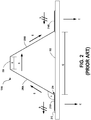
- FIG. 2 is a cross-sectional view of one of the hat stiffeners 104, illustrated as hat stiffener 104A.
- the hat stiffener 104A is formed from various components that together act to provide structure support to the skin 102.
- the components include a hat cap 206, a hat web 208A, 208B and hat flanges 210A, 210B.
- the hat cap 206 is connected to a frame of an aircraft (not shown).
- the hat cap 206 may provide bending stiffness, to the stiffener 104A.
- the hat webs 208A, 208B may offset the hat cap 206 from the skin 102, increasing the hat webs' 208A, 208B contribution to bending stiffness.
- the hat webs 208A, 208B may also provide an out-of-plane shear resistance, allowing the hat stiffener 104A to transfer loads to surrounding structure.
- the hat cap 206 may also absorb in-plane shear.
- the hat webs 208A, 208B can provide a load path to transfer in-plane shear between the skin 102 and the hat cap 206 and the hat cap 206 and the skin 102.
- the hat cap 206 can be connected to another composite structure, such as a second layer of skin (not shown).
- the frame may be mouse holed and step over the hat fastening into the flanges, or a beam would be mounted to the other side of the skin and then attached to the hat by fastening through the attached flanges.
- the hat cap 206 may be attached, however this is typically avoided as it is difficult to inspect anything attached to the cap of a hat.
- the hat web 208A, 208B forms the support structure between the hat cap 206 and the hat flanges 210A, 210B.
- the hat flanges 210A, 210B connect one side of the hat stiffener 104A to a part of the aircraft, such as the skin 102.
- the hat flanges 210A, 210B may be integrally formed with the skin 102 or may be affixed to the skin 102 through the use of an adhesive 212 or other bonding or affixing technology.
- the spacing Q between the inner surfaces of the flange 210A and flange 210B in relation to the length R of the hat cap 206 provide for a stiffener web angle ⁇ .
- the stiffener web angle ⁇ can influence how forces are transferred from the skin 102 to the hat cap 206, and onto other structures in an aircraft for load dissipation.
- the hat cap 206 acts as a force transfer mechanism to transfer forces from the hat web 208, which in turn transfers forces from the web flange 210.
- the hat stiffener 104A can be subjected to various forces in multiple vectors.
- the hat stiffener 104A may be subjected to pull-off force C, which is load force having a direction indicated in FIG. 2 .
- pull-off force C which is load force having a direction indicated in FIG. 2 .
- a desired transfer path for the pull-off force C is from the skin 102, through the hat stiffener 104A, and through other various structures, ending at a frame of the aircraft.
- the hat stiffener 104A may also be subject to a shear force S, which is a force that runs generally normal to the pull-off force C. This shear force S may be a reaction in the hat cap 206 due to shear in the skin 102 and the hat flanges 210A, 210B.
- the shear force S present on the hat cap 206 has an opposite vector to the shear force S present in the skin 102 (demonstrated by two slashes through the force vector on the skin 102).
- This shear may build up in the hat cap 206, also called shear lag, and then get reacted out at the end of the hat stiffener 104A.
- the hat cap 206 may be experience torque, thus requiring the total shear force S to be moved from the hat cap 206 back into the skin 102, causing radius bending issues, discussed in more detail below.
- a desired transfer path for the shear force S may be from the skin 102, into the hat flange 210A, through the hat web 208, the hat cap 206, back to the hat flange 210B and back onto the skin 102.
- the magnitude of the pull-off force C in comparison to shear force S may vary depending on the location of the hat stiffener 104A in the aircraft, or the location along the length of a particular hat stiffener, as well as the particular operation of the aircraft, such as when changing directions, increasing altitude or decreasing altitude, application of cabin pressure, as well as other factors.
- the web angle ⁇ has an impact as to how well the hat stiffener 104A performs when transferring the various forces. For example, a small web angle ⁇ , translating to a relatively large hat web slope, may provide for a better transfer of the pull-off force C, while not transferring the shear force S as well.
- the ability of the hat stiffener 104A to withstand the shear force S at a radius 214 of the hat stiffener 104A may be less than optimal. This can lead to interlaminar tension failures in the radius 214 caused by radius bending, resulting in a structural breakdown of the hat stiffener 104A.
- the hat web slope is the gradient of a line beginning at the intersection of the hat web and the hat flange and ending at the intersection of the hat web and the hat cap.
- a hat web slope may be described herein in terms of a hat web angle, but may also be described in relative terms to another hat web slope.
- the hat web slope at a particular location of the hat stiffener can be configured based on the performance requirements of the hat stiffener at the particular location.
- slopes, angles, and general shapes of the hat stiffeners described herein are exemplary only. Further, the present disclosure is not limited to any specific determination of a degree of slope, as the slopes are relative in nature. The use of the terms “larger” and “smaller” are relative terms.
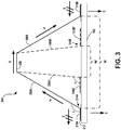
- FIG. 3 a cross-sectional view of an illustrative hat stiffener 304 with varying web angles to provide varying hat web slopes is illustrated.
- the hat stiffener 304 has web angle ⁇ at one location along its length and web angle ⁇ ' at another location along its length, described in additional detail in FIGS. 4-6 below.
- the web angle ⁇ may provide for a first hat web slope
- the web angle ⁇ ' may provide for a second hat web slope.
- Implementations of the presently disclosed subject matter may include two or more hat web slopes. As illustrated in FIG. 3 , the first hat web slope is less than the second hat web slope.
- a relatively large web angle such as the web angle ⁇
- a relatively large web angle can transfer the shear force S between the hat flanges 310A and 310B and the hat cap 306 via the hat webs 308A and 308B better than a relatively smaller web angle, such as the web angle ⁇ '.
- the hat stiffener 304 has a web angle ⁇ ' providing for the second hat web slope.
- the pull-off force C may be effectively transferred from the hat flanges 310A' and 310B', illustrated in more detail in FIG. 4 below, to the hat webs 308A' and 308B', which may transfer the load to another structural component of an aircraft.
- the radius 314B may be better able to withstand the pull-off force C because the smaller web angle ⁇ ' causes less moment to be applied to the radius 314B, causing increased radius bending and interlaminar tension, when compared to the radius 314A.
- the hat stiffener 304 has a web angle ⁇ , providing for a second hat web slope, which may have a hat web slope less than the hat web slope provided by the web angle ⁇ '.
- the shear force S may be effectively transferred between the skin 102 and the hat cap 306 via the hat webs 308A and 308B.
- the radius 314A may be better able to withstand the shear force S than the radius 314B because the larger web angle ⁇ ' causes less moment to be applied to the radius 314A, and therefore decreased radius bending and interlaminar tension, when compared to the radius 314B in a shear force S situation.
- the hat stiffener 304 may be attached to the skin 102 using conventional attachment means.
- the hat stiffener 304 may be affixed to the skin 102 through the use of the adhesive 212.
- Other affixing technologies may be used depending on the materials used to form the various components described herein, including fastening, bonding, co-bonding, co-curing, welding and riveting. The present disclosure is not limited to any particular technology for affixing the hat stiffener 304 to the skin 102.
- Other hat stiffeners, including hat stiffeners constructed according to the concepts described herein, may be affixed to the skin 102 to form a portion of a composite structure for use in an aircraft.
- the varying web angles may also provide for varying internal widths.
- a first internal width W corresponds to the web angle a.
- a second internal width W' that corresponds to the web angle ⁇ '.
- the internal width of the hat stiffener 304 at various locations may vary from the first internal width W to the second internal width W'.
- the first internal width W and the second internal width W' are shown as being measured at a location near the base of the hat flanges 310A and 310B, however, the first internal width W and the second internal width W' may be measured at various locations along the hat stiffener.
- an internal width of the hat stiffener 304 may be varied in ways other than a through changes in a web angle.
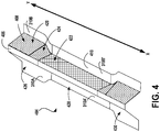
- FIG. 4 is an illustration of a hat stiffener 404 having multiple hat web slopes along the length of the hat stiffener 404.
- the hat stiffener 404 in FIG. 4 has a hat cap 406, a hat web 408 and a hat flange 410.
- the hat web 408 has various slopes along a hat cap length XY of the hat stiffener 404.
- the various slopes described in more detail below, can help the hat stiffener 404 transfer loads more effectively.
- the slope of the hat web 408 may be relatively small in order to reduce the amount of moment felt at the radii of the hat stiffener 404.
- the slope of the hat web 408 may be relatively larger to better transfer the pull-off force C.
- a first hat web slope of the hat stiffener 404 is the web area 420 with the web flanges 310A and 310B.
- the web area 420 is illustrated as having a relatively smaller hat web slope, similar to the hat web slope provided by the web angle ⁇ of FIG. 3 .
- the portion of the hat stiffener 404 having that web angle is configured to handle the sheer force S more effectively than a hat stiffener with a slope provided by the web angle ⁇ '.
- the ability to handle the sheer force S may be useful in locations that are impacted by a higher degree of the sheer force S in comparison to the pull-off force C.
- the hat stiffener portion 426 may be more efficient in a region in which the sheer force S is a greater contributor of force than the pull-off force C.
- a hat stiffener portion 428 may be in a portion of the aircraft where a beam is attached on the other side of the panel, or a bracket is attached, and the like, which may cause the application of a discrete interface load.
- the hat stiffener portion 428 may have a slope provided by the hat web angle ⁇ ' with hat flanges 310A' and 310B'.
- the hat stiffener 404 may be better configured to handle the effects of the pull-off interface force C than the sheer force S.
- the hat stiffener 404 may also have a transition area, hat web area 424, between the hat web area 420 and the hat web area 422.
- the hat web area 424 may have a web with a transitional slope of varying degrees along its length to allow for a transition from the smaller slope of the hat web area 420 to the larger slope of the hat web area 422.
- a transition between the smaller slope of the hat web area 420 to the larger slope of the hat web area 422 may help increase the structural integrity of the hat stiffener 404 by reducing sharp angles.
- hat web area 424 can reduce the effects of the transition while still providing the structural rigidity necessary to perform properly. It should be understood that the present disclosure is not limited to any particular relative hat stiffener portions, as some hat stiffeners may be manufactured with fewer or more hat stiffener portions, illustrated by way of example, in FIG. 5 .
- FIG. 5 is a perspective view of a hat stiffener 504 having fewer web slopes than the hat stiffener 404 of FIG. 4 and a constant width for the hat cap 406.
- the hat stiffener 504 has hat web area 520A.
- the hat web area 520A has a relatively smaller slope, similar to the hat web area 420 of FIG. 4 .
- the hat web area 520A transitions from a smaller slope into a larger slope via hat web area 524A, which provides for a large slope at location 532.
- the slope of the hat stiffener at a location 532 is greater than the slope at the hat web area 520A.
- the profile of the hat stiffener 504 continues from the hat web area 524A to a hat web area 524B, which is a transition from the large slope at the location 532 to the hat web area 520B.
- the hat web area 520B may have a slope similar to the hat web area 520A.
- transition portions such as the hat web areas 524A and 524B, may not have a particular shape.
- the hat web area 424 of FIG. 4 and the hat web areas 524A and 524B of FIG. 5 are shown having a generally concave shape, other configurations may provide for a convex shape. Additionally, various configurations may provide for a variable hat cap size, an example of which is illustrated in FIG. 6 .
- a hat stiffener 604 has a hat web area 620A and a hat web area 620B, both of which may have slopes similar to the hat web areas 520A and 520B of FIG. 5 .
- the hat stiffener 604 has hat web areas 624A and 624B, which transition the slope from the hat web areas 620A and 620B to the slope found at a location 632, which may have a larger slope than the hat web areas 620A and 620B.
- the hat web areas 624A and 624B transition to the larger slope via a convex configuration, in a manner different than the concave transition that may be found in FIGS. 4 and 5 .
- the convex transition provides for a hat cap 606 with variable size along its length.
- the hat cap 606 may have a portion 634 near the end of the hat cap that has a width of A, whereas the hat cap 606 may have a portion 636 near the location 632 that has a width of A+B.
- the location 636 which has a width greater than the location 634, may provide additional benefits.
- the location 636 may provide additional surface area necessary to withstand a particular load.
- the location 636 may provide a better transition from the hat stiffener 604 when optimized to handle the sheer force S to the hat stiffener 604 when optimized to handle the pull-off load C.
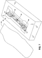
- FIG. 7 is an illustration of a mandrel 700 that may be used to form a hat stiffener, according to the various embodiments described herein.
- the mandrel 700 may be shaped to receive one or more layers of composite material 702.
- the composite material 702 may be a laminate formed from various types of materials. The concepts described herein are not limited to any particular laminate of materials.
- the mandrel 700 has various slopes that, when used to form a hat stiffener according to various configurations described herein, forms a hat stiffener with various slopes.
- the mandrel 700 has an area 704, which may be used to form a hat stiffener portion with a smaller slope, such as the hat web area 420 of FIG. 4 .
- the mandrel 700 may also have transition area 706, which increases the slope of a hat stiffener from the slope of the area 704 to the slope of an area 708.
- the composite material 702 may be placed in the mandrel 700 and formed by conventional curing techniques. It should be understood that the mandrel 700 may be formed from one or more pieces or may be of unitary construction, the technology of which is not limited to any particular configuration.
- FIG. 8 is an illustration of a hat stiffener 804 having flanges with various widths.
- variable widths can provide some functionality. For example, in locations in which the shear force S or the pull off force C may be relatively large, a wider hat flange may provide additional surface area in which the hat stiffener 804 may be attached to the skin 102.
- the hat stiffener 804 has a hat flange 810 with variable widths along the length of the hat flange 810.
- the hat flange 810 has a width of "H”.
- the hat flange 810 has a width of "H+I”.
- the width "H+I" is wider than the width "H”.
- the hat flange 810 has a width of "H”.
- the present disclosure is not limited to any specific order of variation of the width of the hat flange 810.
- the implementation illustrated in FIG. 8 shows a hat flange 810 having a width profile in which the width near the distal ends of the hat stiffener 804 are similar.
- FIG. 9 is a cross-sectional view of a hat stiffener 904 with variable hat heights.
- the hat stiffener 904 includes a hat cap 906, hat webs 908A and 908B, and hat flanges 910A and 910B.
- the hat web slope of the hat stiffener 904 may be changed.
- the height of the hat cap has been modified to accommodate for the variable hat web slope.
- a hat web slope provided by the hat cap 906, the hat webs 908A and 908B, and the hat flanges 910A and 910B provides for a hat height of "L".
- hat stiffener 904 has a hat height of "L+G" provided by the hat cap 906', the hat webs 908A' and 908B', and the hat flanges 910A' and 910B', which is a larger hat web angle than the hat web slope providing the hat height of "L".
- Other components of the hat stiffener may be varied.
- the thickness of the hat stiffener 904 or its constituent components such as, but not limited to, the hat web 908A and 908B, the hat cap 906 and the hat flanges 910A and 910B.
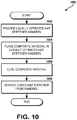
- FIG. 10 an illustrative routine 1000 for forming a hat stiffener with locally optimized hat web slopes is provided herein. Unless otherwise indicated, it should be appreciated that more or fewer operations may be performed than shown in the figures and described herein. Additionally, unless otherwise indicated, these operations may also be performed in a different order than those described herein
- the routine 1000 starts at operation 1002, where a mandrel 700 is provided.
- the mandrel 700 is provided with variable angles for the hat webs.
- the mandrel 700 has a small slope in the areas in which the hat stiffener 404 is desirably configured to handle the shear force S in a more effective manner than the pull-off load C.
- the mandrel 700 has a large web slope in the areas in which the hat stiffener 404 is desirably configured to handle the pull-off load C in a more effective manner than the shear force S.
- the routine 1000 continues from operation 1002 to operation 1004, where the composite material 702 is placed in the mandrel 700.
- the composite material 702 may be a matrix formed from various materials, depending on the particular application.
- the composite material 702 may be placed in the mandrel 700 in one operation or in successive layers, the present technology of which is not limited to any particular configuration.
- the composite material 702 may be placed and secured in the mandrel 700 in various ways. For example, the composite material 702 may be pressed in the mandrel 700 using a bladder (not shown) that fits in the mandrel 700.
- the entire assembly, mandrel 700, composite material 702 and bladder, may then be bagged a vacuum may be applied to create pressure in the assembly to force the composite material 702 to the shape of the mandrel 700 during a curing process.
- a vacuum may be applied to create pressure in the assembly to force the composite material 702 to the shape of the mandrel 700 during a curing process.
- the presently disclosed subject matter is not limited to any particular means of securing the composite material 702 in the mandrel 700.
- the routine 1000 continues from operation 1004 to operation 1006, where the composite material 702 is cured.
- the concepts and technologies described herein are not limited to any particular curing process.
- the temperature or pressure may be varied to account for additional material that may be present in some areas of the hat stiffener 404 than other areas due to the changing slopes.
- the presently disclosed subject matter is not limited to any particular temperature or pressure profile for curing.
- the routine 1000 continues from operation 1006 to operation 1008, where the cured hat stiffener is removed from the mandrel 700.
- the hat stiffener includes locally optimized hat web slopes formed by the various angles in the mandrel 700 corresponding to the hat webs. It should be understood that the present technology is not limited to any particular removal process. Further, as part of the removal process, some material of the now-cured composite material 702 may be removed to shape the hat stiffener according to a required design configuration. The routine 1000 thereafter ends.
- FIG. 11 is an illustrative routine for using a hat stiffener, according to various embodiments.
- Routine 1100 begins and proceeds to operation 1102, where an operational force is received at a locally optimized hat stiffener
- a locally optimized hat stiffener may perform certain functions.
- a first function may be to pick up loads applied to the skin, collect the loads, and then transfer those loads onto or into other, more robust structures capable of handling the loads.
- the loads may be due to various operational forces, including, but not limited to, pressure loading or some other locally applied or distributed loading.
- the applied load locations, or interfaces with other structures may be locations that develop a significant amount of pull-off loading.
- a second function may be to stabilize the skin.
- the locally optimized hat stiffeners of the present disclosure may do this by supplying out-of-plane stiffness, thereby reducing the likelihood of a panel buckling or failing.
- hat stiffeners may have a wide footprint, which may be an effective mechanism for stabilizing a relatively large area of panel.
- the torsional stiffness, and shear stiffness may also help stabilize a panel as well.
- the hat stiffeners may generally take the pressure load and redistribute it to the surrounding structure.
- the fuselage, and bulkheads in the structure may be subjected to loads. Different areas of the fuselage will see elevated shear loading for different loading scenarios.
- Routine 1100 proceeds from operation 1102 to operation 1104, where the locally optimized hat stiffener absorbs (or collects) at least a portion of the operational force.
- the operational force may be absorbed by more than one locally optimized hat stiffener. Due to local optimization, a hat stiffener according to various configurations described herein may absorb the operational force at various locations along the length of the hat stiffener. For example, a location on the hat stiffener optimized for one type of operational force may not absorb an appreciable amount of the operational force, whereas a location on the hat stiffener optimized for the operational force may absorb a significant portion of the operational force.
- Routine 1100 proceeds from operation 1104 to operation 1106, where the absorbed operational forces are distributed to the surrounding structure.
- the surrounding structure may include, but is not limited to, a frame of the aircraft, other panels, and the like.
- the routine 1100 thereafter ends.
- a composite structure comprising a composite skin; and a plurality of hat stiffeners (104) affixed to the composite skin, the plurality of hat stiffeners comprising a hat cap (206) having a hat cap (206) length, a plurality of hat flanges (210A, 210B) along the hat cap (206) length, and a hat web (208A, 208B) having a first slope along the hat cap (206) length and a second slope along the hat cap (206) length, wherein the second slope is greater than the first slope.
- the first slope may be configured for a shear force.
- the second slope may be configured for a pull-off force.
- the hat web may further comprise a transitional slope.
- the transitional slope may provide a transition from the first slope to the second slope.
- the hat web may further comprise a third slope.
- a height of the hat stiffener may vary along a length of the hat stiffener.
- a width of the hat cap may vary along the hat cap length. At least a portion of the plurality of hat stiffeners may further comprise a first internal width and the second internal width.
Landscapes
- Engineering & Computer Science (AREA)
- Mechanical Engineering (AREA)
- Aviation & Aerospace Engineering (AREA)
- Architecture (AREA)
- Civil Engineering (AREA)
- Structural Engineering (AREA)
- Moulding By Coating Moulds (AREA)
- Laminated Bodies (AREA)
- Helmets And Other Head Coverings (AREA)
- Turbine Rotor Nozzle Sealing (AREA)
Claims (6)
- Kappenversteifung zum Verstärken einer Flugzeughülle, die Kappenversteifung beinhaltend:einen Kappendeckel (206) mit einer Kappendeckel- (206) Länge;mehrere Kappenflansche (210A, 210B, 410) entlang der Kappendeckel- (206) Länge, wobei ein Abstand zwischen Innenflächen der mehreren Kappenflansche (210A, 210B, 410) entlang der Gesamtheit der Kappendeckel- (206) Länge verläuft; undeinen Kappensteg (208A, 208B) zwischen dem Kappendeckel (206) und den mehreren Kappenflanschen (210A, 210B, 410), wobei der Kappensteg eine erste Neigung (420, 520A, 620A) entlang eines Abschnitts der Kappendeckel- (206) Länge hat und ein zweite Neigung (422, 532, 632) entlang eines anderen Abschnitts der Kappendeckel- (206) Länge hat, dadurch gekennzeichnet, dass die zweite Neigung größer ist als die erste Neigung, wobei der Kappensteg (208A, 208B) ferner beinhaltet: eine erste Übergangsneigung (424, 524A, 624A), die einen Übergang von der ersten Neigung zur zweiten Neigung vorsieht; eine dritte Neigung (520B, 620B), die dieselbe wie die erste Neigung ist; und eine zweite Übergangsneigung (524B, 624B), die einen Übergang von der zweiten Neigung zur dritten Neigung vorsieht.
- Kappenversteifung nach Anspruch 1, wobei eine Breite des Kappendeckels (206) entlang der Kappendeckel- (206) Länge variiert.
- Kappenversteifung nach Anspruch 2, wobei die Breite des Kappendeckels (206) entsprechend der zweiten Neigung größer ist als die Breite des Kappendeckels (206) entsprechend der ersten Neigung.
- Kappenversteifung nach einem der Ansprüche 1 - 3, ferner beinhaltend:eine Komposithülle.
- Verfahren zur Bildung einer Kappenversteifung nach Anspruch 1, das Verfahren beinhaltend:Vorsehen einer Form (700) mit einem ersten Kappensteg-(208A, 208B) Abschnitt, der angeordnet ist, die erste Neigung entlang der Kappendeckel- (206) Länge zu definieren, und einem zweiten Kappensteg- (208A, 208B) Abschnitt, der angeordnet ist, die zweite Neigung entlang der Kappendeckel-(206) Länge zu definieren;Vorsehen eines Kompositmaterials;Platzieren des Kompositmaterials in der Form;Härten des Kompositmaterials; undEntfernen des Kompositmaterials, um eine Kappenverstärkung mit lokal optimierten Kappensteg-(208A, 208B) Neigungen vorzusehen.
- Verfahren nach Anspruch 5, ferner beinhaltend ein Formen der Kappenversteifung (104).
Priority Applications (1)
| Application Number | Priority Date | Filing Date | Title |
|---|---|---|---|
| EP17198687.0A EP3309056B1 (de) | 2013-05-30 | 2014-04-15 | Verbundstoffhutversteifer |
Applications Claiming Priority (1)
| Application Number | Priority Date | Filing Date | Title |
|---|---|---|---|
| US13/905,294 US10308343B2 (en) | 2013-05-30 | 2013-05-30 | Composite hat stiffener |
Related Child Applications (2)
| Application Number | Title | Priority Date | Filing Date |
|---|---|---|---|
| EP17198687.0A Division EP3309056B1 (de) | 2013-05-30 | 2014-04-15 | Verbundstoffhutversteifer |
| EP17198687.0A Division-Into EP3309056B1 (de) | 2013-05-30 | 2014-04-15 | Verbundstoffhutversteifer |
Publications (2)
| Publication Number | Publication Date |
|---|---|
| EP2808249A1 EP2808249A1 (de) | 2014-12-03 |
| EP2808249B1 true EP2808249B1 (de) | 2018-01-10 |
Family
ID=50479085
Family Applications (2)
| Application Number | Title | Priority Date | Filing Date |
|---|---|---|---|
| EP17198687.0A Active EP3309056B1 (de) | 2013-05-30 | 2014-04-15 | Verbundstoffhutversteifer |
| EP14164751.1A Active EP2808249B1 (de) | 2013-05-30 | 2014-04-15 | Verbundstoffhutversteifer |
Family Applications Before (1)
| Application Number | Title | Priority Date | Filing Date |
|---|---|---|---|
| EP17198687.0A Active EP3309056B1 (de) | 2013-05-30 | 2014-04-15 | Verbundstoffhutversteifer |
Country Status (10)
| Country | Link |
|---|---|
| US (1) | US10308343B2 (de) |
| EP (2) | EP3309056B1 (de) |
| JP (1) | JP6534503B2 (de) |
| KR (1) | KR102140346B1 (de) |
| CN (2) | CN107738741B (de) |
| AU (1) | AU2014201363B2 (de) |
| BR (1) | BR102014012851B8 (de) |
| CA (1) | CA2845742C (de) |
| ES (2) | ES2755832T3 (de) |
| RU (1) | RU2595713C2 (de) |
Families Citing this family (7)
| Publication number | Priority date | Publication date | Assignee | Title |
|---|---|---|---|---|
| JP6501511B2 (ja) * | 2014-12-15 | 2019-04-17 | 三菱重工業株式会社 | コーナーフィレット部の設計方法及び航空機 |
| EP3281861B1 (de) * | 2016-08-11 | 2019-10-02 | AIRBUS HELICOPTERS DEUTSCHLAND GmbH | Drehflügler mit einem rumpf mit mindestens einem strukturell versteiften paneel |
| DE102017001226B4 (de) * | 2017-02-09 | 2019-04-18 | Schenck Process Europe Gmbh | Förder- und Dosiervorrichtung |
| CN108438199A (zh) * | 2018-03-23 | 2018-08-24 | 太原科技大学 | 一种提高飞机蒙皮承载力的复合材料加强件 |
| GB2584634A (en) * | 2019-05-31 | 2020-12-16 | Airbus Operations Ltd | Aircraft assembly having an integral spar-cover |
| CN111828517B (zh) * | 2020-04-21 | 2024-06-07 | 华侨大学 | 一种分形式梯度帽形复合结构 |
| CN116654322A (zh) * | 2023-06-30 | 2023-08-29 | 中复神鹰碳纤维股份有限公司 | 一种无人机机翼及无人机 |
Family Cites Families (19)
| Publication number | Priority date | Publication date | Assignee | Title |
|---|---|---|---|---|
| SE9601246L (sv) | 1996-04-01 | 1997-10-02 | Plannja Hardtech Ab | Skyddsbalk |
| WO2009050553A1 (en) * | 2007-10-17 | 2009-04-23 | Toyota Jidosha Kabushiki Kaisha | Formed article for vehicle body structural member |
| US7293737B2 (en) | 2004-04-20 | 2007-11-13 | The Boeing Company | Co-cured stringers and associated mandrel and fabrication method |
| WO2006025315A1 (ja) | 2004-08-31 | 2006-03-09 | Toray Industries, Inc. | 自動車用ボンネット |
| GB0614087D0 (en) * | 2006-07-14 | 2006-08-23 | Airbus Uk Ltd | Composite manufacturing method |
| US7628679B2 (en) | 2006-10-16 | 2009-12-08 | The Boeing Company | Trimming composite skin stiffener ends |
| US7871040B2 (en) | 2006-11-10 | 2011-01-18 | The Boeing Company | Composite aircraft structures with hat stiffeners |
| US7854874B2 (en) | 2006-11-20 | 2010-12-21 | The Boeing Company | Apparatus and methods for forming hat stiffened composite parts using thermally expansive tooling cauls |
| US20090004425A1 (en) * | 2007-06-28 | 2009-01-01 | The Boeing Company | Ceramic Matrix Composite Structure having Fluted Core and Method for Making the Same |
| DE102007033868B4 (de) | 2007-07-20 | 2013-01-31 | Airbus Operations Gmbh | Profil mit wenigstens einem Hohlprofilquerschnitt |
| US8019926B2 (en) * | 2008-07-03 | 2011-09-13 | Quantum Corporation | Automatically assigning a multi-dimensional physical address to a data storage device |
| ES2390318B1 (es) * | 2009-03-10 | 2013-09-16 | Airbus Operations, S.L. | Estructura cerrada en material compuesto. |
| US8074694B2 (en) | 2009-05-28 | 2011-12-13 | The Boeing Company | Stringer transition method |
| US8262969B2 (en) | 2009-10-09 | 2012-09-11 | Spirit Aerosystems, Inc. | Apparatus and method for manufacturing an aircraft stringer |
| US8714485B2 (en) | 2009-12-15 | 2014-05-06 | The Boeing Company | Method of fabricating a hat stringer |
| US8636252B2 (en) * | 2010-06-25 | 2014-01-28 | The Boeing Company | Composite structures having integrated stiffeners with smooth runouts and method of making the same |
| US8795567B2 (en) | 2010-09-23 | 2014-08-05 | The Boeing Company | Method for fabricating highly contoured composite stiffeners with reduced wrinkling |
| DE102010063076A1 (de) * | 2010-12-14 | 2012-06-14 | Airbus Operations Gmbh | Befestigungsanordnung sowie Befestigungsbeschlag zum Befestigen eines Bauteils an ein Strukturbauteil eines Luft- oder Raumfahrzeuges |
| EP2781450B1 (de) | 2013-03-19 | 2018-05-02 | Airbus Operations GmbH | System und Verfahren zum Verbinden von Verbundstoffstrukturen miteinander |
-
2013
- 2013-05-30 US US13/905,294 patent/US10308343B2/en active Active
-
2014
- 2014-03-11 CA CA2845742A patent/CA2845742C/en active Active
- 2014-03-11 AU AU2014201363A patent/AU2014201363B2/en active Active
- 2014-04-09 KR KR1020140042557A patent/KR102140346B1/ko active Active
- 2014-04-15 EP EP17198687.0A patent/EP3309056B1/de active Active
- 2014-04-15 ES ES17198687T patent/ES2755832T3/es active Active
- 2014-04-15 ES ES14164751.1T patent/ES2665025T3/es active Active
- 2014-04-15 EP EP14164751.1A patent/EP2808249B1/de active Active
- 2014-04-17 RU RU2014115429/05A patent/RU2595713C2/ru active
- 2014-04-28 JP JP2014093178A patent/JP6534503B2/ja active Active
- 2014-05-15 CN CN201710962055.4A patent/CN107738741B/zh active Active
- 2014-05-15 CN CN201410204220.6A patent/CN104210643B/zh active Active
- 2014-05-28 BR BR102014012851A patent/BR102014012851B8/pt active IP Right Grant
Non-Patent Citations (1)
| Title |
|---|
| None * |
Also Published As
| Publication number | Publication date |
|---|---|
| ES2755832T3 (es) | 2020-04-23 |
| JP2014240268A (ja) | 2014-12-25 |
| JP6534503B2 (ja) | 2019-06-26 |
| KR20140141435A (ko) | 2014-12-10 |
| BR102014012851A2 (pt) | 2015-03-31 |
| BR102014012851B1 (pt) | 2021-05-25 |
| RU2595713C2 (ru) | 2016-08-27 |
| KR102140346B1 (ko) | 2020-08-03 |
| CN107738741B (zh) | 2020-07-24 |
| RU2014115429A (ru) | 2015-10-27 |
| BR102014012851B8 (pt) | 2023-04-25 |
| US10308343B2 (en) | 2019-06-04 |
| CN104210643B (zh) | 2017-11-17 |
| EP3309056A1 (de) | 2018-04-18 |
| CA2845742A1 (en) | 2014-11-30 |
| EP2808249A1 (de) | 2014-12-03 |
| EP3309056B1 (de) | 2019-08-14 |
| CN107738741A (zh) | 2018-02-27 |
| AU2014201363B2 (en) | 2017-07-20 |
| ES2665025T3 (es) | 2018-04-24 |
| US20140356581A1 (en) | 2014-12-04 |
| AU2014201363A1 (en) | 2014-12-18 |
| CA2845742C (en) | 2017-04-18 |
| CN104210643A (zh) | 2014-12-17 |
Similar Documents
| Publication | Publication Date | Title |
|---|---|---|
| EP2808249B1 (de) | Verbundstoffhutversteifer | |
| EP2703283B1 (de) | Zusammengesetzter Verbundflugzeugflügel | |
| JP6374570B2 (ja) | 複合材製ハット形補強材、複合材製ハット形補強加圧ウェブ、及びこれらの部材の形成方法 | |
| EP3301014B1 (de) | Tragflächenförmiger körper mit hülle auf verbundstoffbasis mit integriertem hutförmigen holm | |
| US8434716B2 (en) | Compliant crown panel for an aircraft | |
| EP1616061B1 (de) | Kontaktversteifer für konstruktionshaut | |
| US8490920B2 (en) | Composite bulkhead and skin construction | |
| US9694898B2 (en) | Methods for manufacturing an I-stringer of an aircraft and devices for use in such methods | |
| EP3415308B1 (de) | Verfahren zur montage eines flugzeugrumpfes | |
| CA2768957C (en) | Composite-material structure and aircraft main wing and aircraft fuselage provided with the same | |
| US10843416B2 (en) | Composite reinforcement structures and aircraft assemblies comprising composite reinforcement structures | |
| EP2080612B2 (de) | Verteilung von Punktlasten in Wabenverbundplatten | |
| EP2076431B1 (de) | Flügelplattenstruktur | |
| EP3450302A1 (de) | Energieabsorbierender unterbodenrahmen eines fluggeräts | |
| CN111824393A (zh) | 飞机主起落架阻力支架备用配件组件及相关方法 | |
| US20240174344A1 (en) | Flow body for an aircraft with split ribs |
Legal Events
| Date | Code | Title | Description |
|---|---|---|---|
| PUAI | Public reference made under article 153(3) epc to a published international application that has entered the european phase |
Free format text: ORIGINAL CODE: 0009012 |
|
| 17P | Request for examination filed |
Effective date: 20140415 |
|
| AK | Designated contracting states |
Kind code of ref document: A1 Designated state(s): AL AT BE BG CH CY CZ DE DK EE ES FI FR GB GR HR HU IE IS IT LI LT LU LV MC MK MT NL NO PL PT RO RS SE SI SK SM TR |
|
| AX | Request for extension of the european patent |
Extension state: BA ME |
|
| 17Q | First examination report despatched |
Effective date: 20160517 |
|
| RIC1 | Information provided on ipc code assigned before grant |
Ipc: B29D 99/00 20100101ALI20170517BHEP Ipc: B64C 1/06 20060101AFI20170517BHEP Ipc: B64C 1/12 20060101ALI20170517BHEP |
|
| GRAP | Despatch of communication of intention to grant a patent |
Free format text: ORIGINAL CODE: EPIDOSNIGR1 |
|
| INTG | Intention to grant announced |
Effective date: 20170725 |
|
| GRAS | Grant fee paid |
Free format text: ORIGINAL CODE: EPIDOSNIGR3 |
|
| GRAA | (expected) grant |
Free format text: ORIGINAL CODE: 0009210 |
|
| AK | Designated contracting states |
Kind code of ref document: B1 Designated state(s): AL AT BE BG CH CY CZ DE DK EE ES FI FR GB GR HR HU IE IS IT LI LT LU LV MC MK MT NL NO PL PT RO RS SE SI SK SM TR |
|
| REG | Reference to a national code |
Ref country code: CH Ref legal event code: EP Ref country code: AT Ref legal event code: REF Ref document number: 962088 Country of ref document: AT Kind code of ref document: T Effective date: 20180115 |
|
| REG | Reference to a national code |
Ref country code: IE Ref legal event code: FG4D |
|
| REG | Reference to a national code |
Ref country code: DE Ref legal event code: R096 Ref document number: 602014019769 Country of ref document: DE |
|
| REG | Reference to a national code |
Ref country code: ES Ref legal event code: FG2A Ref document number: 2665025 Country of ref document: ES Kind code of ref document: T3 Effective date: 20180424 |
|
| REG | Reference to a national code |
Ref country code: FR Ref legal event code: PLFP Year of fee payment: 5 |
|
| REG | Reference to a national code |
Ref country code: NL Ref legal event code: MP Effective date: 20180110 |
|
| REG | Reference to a national code |
Ref country code: AT Ref legal event code: MK05 Ref document number: 962088 Country of ref document: AT Kind code of ref document: T Effective date: 20180110 |
|
| PG25 | Lapsed in a contracting state [announced via postgrant information from national office to epo] |
Ref country code: NL Free format text: LAPSE BECAUSE OF FAILURE TO SUBMIT A TRANSLATION OF THE DESCRIPTION OR TO PAY THE FEE WITHIN THE PRESCRIBED TIME-LIMIT Effective date: 20180110 |
|
| PG25 | Lapsed in a contracting state [announced via postgrant information from national office to epo] |
Ref country code: CY Free format text: LAPSE BECAUSE OF FAILURE TO SUBMIT A TRANSLATION OF THE DESCRIPTION OR TO PAY THE FEE WITHIN THE PRESCRIBED TIME-LIMIT Effective date: 20180110 Ref country code: FI Free format text: LAPSE BECAUSE OF FAILURE TO SUBMIT A TRANSLATION OF THE DESCRIPTION OR TO PAY THE FEE WITHIN THE PRESCRIBED TIME-LIMIT Effective date: 20180110 Ref country code: NO Free format text: LAPSE BECAUSE OF FAILURE TO SUBMIT A TRANSLATION OF THE DESCRIPTION OR TO PAY THE FEE WITHIN THE PRESCRIBED TIME-LIMIT Effective date: 20180410 Ref country code: LT Free format text: LAPSE BECAUSE OF FAILURE TO SUBMIT A TRANSLATION OF THE DESCRIPTION OR TO PAY THE FEE WITHIN THE PRESCRIBED TIME-LIMIT Effective date: 20180110 Ref country code: HR Free format text: LAPSE BECAUSE OF FAILURE TO SUBMIT A TRANSLATION OF THE DESCRIPTION OR TO PAY THE FEE WITHIN THE PRESCRIBED TIME-LIMIT Effective date: 20180110 |
|
| PG25 | Lapsed in a contracting state [announced via postgrant information from national office to epo] |
Ref country code: SE Free format text: LAPSE BECAUSE OF FAILURE TO SUBMIT A TRANSLATION OF THE DESCRIPTION OR TO PAY THE FEE WITHIN THE PRESCRIBED TIME-LIMIT Effective date: 20180110 Ref country code: LV Free format text: LAPSE BECAUSE OF FAILURE TO SUBMIT A TRANSLATION OF THE DESCRIPTION OR TO PAY THE FEE WITHIN THE PRESCRIBED TIME-LIMIT Effective date: 20180110 Ref country code: RS Free format text: LAPSE BECAUSE OF FAILURE TO SUBMIT A TRANSLATION OF THE DESCRIPTION OR TO PAY THE FEE WITHIN THE PRESCRIBED TIME-LIMIT Effective date: 20180110 Ref country code: AT Free format text: LAPSE BECAUSE OF FAILURE TO SUBMIT A TRANSLATION OF THE DESCRIPTION OR TO PAY THE FEE WITHIN THE PRESCRIBED TIME-LIMIT Effective date: 20180110 Ref country code: BG Free format text: LAPSE BECAUSE OF FAILURE TO SUBMIT A TRANSLATION OF THE DESCRIPTION OR TO PAY THE FEE WITHIN THE PRESCRIBED TIME-LIMIT Effective date: 20180410 Ref country code: GR Free format text: LAPSE BECAUSE OF FAILURE TO SUBMIT A TRANSLATION OF THE DESCRIPTION OR TO PAY THE FEE WITHIN THE PRESCRIBED TIME-LIMIT Effective date: 20180411 Ref country code: IS Free format text: LAPSE BECAUSE OF FAILURE TO SUBMIT A TRANSLATION OF THE DESCRIPTION OR TO PAY THE FEE WITHIN THE PRESCRIBED TIME-LIMIT Effective date: 20180510 Ref country code: PL Free format text: LAPSE BECAUSE OF FAILURE TO SUBMIT A TRANSLATION OF THE DESCRIPTION OR TO PAY THE FEE WITHIN THE PRESCRIBED TIME-LIMIT Effective date: 20180110 |
|
| REG | Reference to a national code |
Ref country code: DE Ref legal event code: R097 Ref document number: 602014019769 Country of ref document: DE |
|
| PG25 | Lapsed in a contracting state [announced via postgrant information from national office to epo] |
Ref country code: RO Free format text: LAPSE BECAUSE OF FAILURE TO SUBMIT A TRANSLATION OF THE DESCRIPTION OR TO PAY THE FEE WITHIN THE PRESCRIBED TIME-LIMIT Effective date: 20180110 Ref country code: EE Free format text: LAPSE BECAUSE OF FAILURE TO SUBMIT A TRANSLATION OF THE DESCRIPTION OR TO PAY THE FEE WITHIN THE PRESCRIBED TIME-LIMIT Effective date: 20180110 Ref country code: AL Free format text: LAPSE BECAUSE OF FAILURE TO SUBMIT A TRANSLATION OF THE DESCRIPTION OR TO PAY THE FEE WITHIN THE PRESCRIBED TIME-LIMIT Effective date: 20180110 |
|
| PLBE | No opposition filed within time limit |
Free format text: ORIGINAL CODE: 0009261 |
|
| STAA | Information on the status of an ep patent application or granted ep patent |
Free format text: STATUS: NO OPPOSITION FILED WITHIN TIME LIMIT |
|
| PG25 | Lapsed in a contracting state [announced via postgrant information from national office to epo] |
Ref country code: DK Free format text: LAPSE BECAUSE OF FAILURE TO SUBMIT A TRANSLATION OF THE DESCRIPTION OR TO PAY THE FEE WITHIN THE PRESCRIBED TIME-LIMIT Effective date: 20180110 Ref country code: SM Free format text: LAPSE BECAUSE OF FAILURE TO SUBMIT A TRANSLATION OF THE DESCRIPTION OR TO PAY THE FEE WITHIN THE PRESCRIBED TIME-LIMIT Effective date: 20180110 Ref country code: SK Free format text: LAPSE BECAUSE OF FAILURE TO SUBMIT A TRANSLATION OF THE DESCRIPTION OR TO PAY THE FEE WITHIN THE PRESCRIBED TIME-LIMIT Effective date: 20180110 Ref country code: MC Free format text: LAPSE BECAUSE OF FAILURE TO SUBMIT A TRANSLATION OF THE DESCRIPTION OR TO PAY THE FEE WITHIN THE PRESCRIBED TIME-LIMIT Effective date: 20180110 Ref country code: CZ Free format text: LAPSE BECAUSE OF FAILURE TO SUBMIT A TRANSLATION OF THE DESCRIPTION OR TO PAY THE FEE WITHIN THE PRESCRIBED TIME-LIMIT Effective date: 20180110 |
|
| REG | Reference to a national code |
Ref country code: CH Ref legal event code: PL |
|
| 26N | No opposition filed |
Effective date: 20181011 |
|
| REG | Reference to a national code |
Ref country code: BE Ref legal event code: MM Effective date: 20180430 |
|
| REG | Reference to a national code |
Ref country code: IE Ref legal event code: MM4A |
|
| PG25 | Lapsed in a contracting state [announced via postgrant information from national office to epo] |
Ref country code: LU Free format text: LAPSE BECAUSE OF NON-PAYMENT OF DUE FEES Effective date: 20180415 |
|
| PG25 | Lapsed in a contracting state [announced via postgrant information from national office to epo] |
Ref country code: LI Free format text: LAPSE BECAUSE OF NON-PAYMENT OF DUE FEES Effective date: 20180430 Ref country code: BE Free format text: LAPSE BECAUSE OF NON-PAYMENT OF DUE FEES Effective date: 20180430 Ref country code: SI Free format text: LAPSE BECAUSE OF FAILURE TO SUBMIT A TRANSLATION OF THE DESCRIPTION OR TO PAY THE FEE WITHIN THE PRESCRIBED TIME-LIMIT Effective date: 20180110 Ref country code: CH Free format text: LAPSE BECAUSE OF NON-PAYMENT OF DUE FEES Effective date: 20180430 |
|
| PG25 | Lapsed in a contracting state [announced via postgrant information from national office to epo] |
Ref country code: IE Free format text: LAPSE BECAUSE OF NON-PAYMENT OF DUE FEES Effective date: 20180415 |
|
| PG25 | Lapsed in a contracting state [announced via postgrant information from national office to epo] |
Ref country code: MT Free format text: LAPSE BECAUSE OF NON-PAYMENT OF DUE FEES Effective date: 20180415 |
|
| PG25 | Lapsed in a contracting state [announced via postgrant information from national office to epo] |
Ref country code: TR Free format text: LAPSE BECAUSE OF FAILURE TO SUBMIT A TRANSLATION OF THE DESCRIPTION OR TO PAY THE FEE WITHIN THE PRESCRIBED TIME-LIMIT Effective date: 20180110 |
|
| PG25 | Lapsed in a contracting state [announced via postgrant information from national office to epo] |
Ref country code: HU Free format text: LAPSE BECAUSE OF FAILURE TO SUBMIT A TRANSLATION OF THE DESCRIPTION OR TO PAY THE FEE WITHIN THE PRESCRIBED TIME-LIMIT; INVALID AB INITIO Effective date: 20140415 Ref country code: PT Free format text: LAPSE BECAUSE OF FAILURE TO SUBMIT A TRANSLATION OF THE DESCRIPTION OR TO PAY THE FEE WITHIN THE PRESCRIBED TIME-LIMIT Effective date: 20180110 |
|
| PG25 | Lapsed in a contracting state [announced via postgrant information from national office to epo] |
Ref country code: MK Free format text: LAPSE BECAUSE OF NON-PAYMENT OF DUE FEES Effective date: 20180110 |
|
| P01 | Opt-out of the competence of the unified patent court (upc) registered |
Effective date: 20230516 |
|
| PGFP | Annual fee paid to national office [announced via postgrant information from national office to epo] |
Ref country code: DE Payment date: 20250429 Year of fee payment: 12 |
|
| PGFP | Annual fee paid to national office [announced via postgrant information from national office to epo] |
Ref country code: GB Payment date: 20250428 Year of fee payment: 12 Ref country code: ES Payment date: 20250505 Year of fee payment: 12 |
|
| PGFP | Annual fee paid to national office [announced via postgrant information from national office to epo] |
Ref country code: IT Payment date: 20250422 Year of fee payment: 12 |
|
| PGFP | Annual fee paid to national office [announced via postgrant information from national office to epo] |
Ref country code: FR Payment date: 20250425 Year of fee payment: 12 |