EP2808184B1 - Double hitch assembly for a vehicle - Google Patents
Double hitch assembly for a vehicle Download PDFInfo
- Publication number
- EP2808184B1 EP2808184B1 EP14170316.5A EP14170316A EP2808184B1 EP 2808184 B1 EP2808184 B1 EP 2808184B1 EP 14170316 A EP14170316 A EP 14170316A EP 2808184 B1 EP2808184 B1 EP 2808184B1
- Authority
- EP
- European Patent Office
- Prior art keywords
- flange
- hitch
- hitch assembly
- assembly according
- vehicle
- Prior art date
- Legal status (The legal status is an assumption and is not a legal conclusion. Google has not performed a legal analysis and makes no representation as to the accuracy of the status listed.)
- Active
Links
Images


Classifications
-
- B—PERFORMING OPERATIONS; TRANSPORTING
- B60—VEHICLES IN GENERAL
- B60D—VEHICLE CONNECTIONS
- B60D1/00—Traction couplings; Hitches; Draw-gear; Towing devices
- B60D1/01—Traction couplings or hitches characterised by their type
- B60D1/07—Multi-hitch devices, i.e. comprising several hitches of the same or of a different type; Hitch-adaptors, i.e. for converting hitches from one type to another
-
- B—PERFORMING OPERATIONS; TRANSPORTING
- B60—VEHICLES IN GENERAL
- B60D—VEHICLE CONNECTIONS
- B60D1/00—Traction couplings; Hitches; Draw-gear; Towing devices
- B60D1/01—Traction couplings or hitches characterised by their type
- B60D1/02—Bolt or shackle-type couplings
-
- B—PERFORMING OPERATIONS; TRANSPORTING
- B60—VEHICLES IN GENERAL
- B60D—VEHICLE CONNECTIONS
- B60D1/00—Traction couplings; Hitches; Draw-gear; Towing devices
- B60D1/01—Traction couplings or hitches characterised by their type
- B60D1/06—Ball-and-socket hitches, e.g. constructional details, auxiliary devices, their arrangement on the vehicle
-
- B—PERFORMING OPERATIONS; TRANSPORTING
- B60—VEHICLES IN GENERAL
- B60D—VEHICLE CONNECTIONS
- B60D1/00—Traction couplings; Hitches; Draw-gear; Towing devices
- B60D1/48—Traction couplings; Hitches; Draw-gear; Towing devices characterised by the mounting
- B60D1/485—Traction couplings; Hitches; Draw-gear; Towing devices characterised by the mounting mounted by means of transversal members attached to the frame of a vehicle
-
- B—PERFORMING OPERATIONS; TRANSPORTING
- B60—VEHICLES IN GENERAL
- B60D—VEHICLE CONNECTIONS
- B60D1/00—Traction couplings; Hitches; Draw-gear; Towing devices
- B60D1/48—Traction couplings; Hitches; Draw-gear; Towing devices characterised by the mounting
- B60D1/52—Traction couplings; Hitches; Draw-gear; Towing devices characterised by the mounting removably mounted
Definitions
- the present invention relates to a dual hitch assembly for a vehicle, in particular a traction motor vehicle.
- the hitch assemblies concerned by the present invention are more particularly the assemblies comprising two distinct coupling modes for towing a towed vehicle so as to be able to couple two different types of trailers.
- the document FR-2,740,079 discloses a horse drawn carriage which has two coupling means of the same type.
- the assembly proposed in this document requires an adaptation of both the towing vehicle and the towed assembly.
- the object of the invention is therefore to provide a hitch assembly offering two different coupling modes at specific mounting heights while having a unique mode of connection with a traction vehicle chassis.
- the invention also aims to provide such a coupling assembly wherein the traction of the trailer is carried out in all cases in the median plane of the vehicle. As a result, there is a braking torque and acceleration torque in the hitch. The latter must be designed to withstand this cyclic torque, including fatigue.
- the document EP-2,596,966 discloses a coupling assembly with first coupling means and second coupling means arranged one above the other.
- the first coupling means and the second coupling means are fixed on a mounting plate and the mounting plate is fixed on a drawbar by means of fixing means comprising two brackets each having a first wing and a second wing, the first wings of the brackets being fixed on two opposite faces of the drawbar and the two second wings defining a plane on which is fixed the mounting plate.
- An object of the present invention is to provide a compact hitch device so as to limit the size of the hitch at the rear of the vehicle to which the hitch device is intended.
- the vertically measured distance (or altitude) between a first coupling means corresponding to a first coupling mode and a second coupling means corresponding to a second coupling mode is preferably reduced.
- the coupling device will preferably further easy to integrate on a vehicle and ergonomic.
- the invention will allow coupling to the choice of a trailer having a standard ball hitch system, or a non-standard hitch coupling system.
- the invention also aims to provide a traction motor vehicle with a hitch assembly that allows to hitch the choice of trailers with different types of hitch.
- a double hitch assembly for a vehicle comprising first hitching means, second hitching means and two brackets each having a first wing and a second wing.
- the first wings are fixed parallel to each other vis-à-vis; the second wings are arranged such that they extend from the corresponding first wing away from the other square and so that the second wings are parallel but offset, and the first coupling means and the second coupling means are each fixed to a second wing of a square.
- This new structure makes it possible, thanks to the offset of the second wings, to no longer have the coupling means one above the other. As a result, the hitching means can be brought together, thus making it possible to produce a compact hitch assembly.
- a hitch assembly according to the invention may further comprise a drawbar.
- the brackets are for example bolted to the drawbar sandwiched between the first two wings of the brackets.
- “Drawbar” means any beam, beam, crosshead type, hitch function, attached to the chassis of the vehicle or making integral part of it.
- the frame may be a frame-type chassis, or mechanically welded, tubular, or chassis-hull type, or more generally any vehicle supporting structure.
- brackets are advantageously fixed on the drawbar with bolts passing through the drawbar vertically from one side to the other. This solution simplifies the assembly of the assembly according to the invention.
- first coupling means and the second coupling means are bolted to the second wings of the brackets.
- At least one bracket has an additional face extending from the first wing parallel to the second wing but in the opposite direction. We can then provide a fixation of this additional face on a drawbar or other in a direction perpendicular to the attachment of the first wings.
- the first wing of said bracket preferably comprises a first edge from which the second wing extends and a second edge opposite to the first edge and from which the additional face extends.
- the bracket then has a Z shape.
- the additional face is in the extension of the second wing. We would then have a T-section of the square, the base of the T being formed by the first wing.
- a preferred embodiment provides for the two brackets of the hitch assembly to have a Z-shape.
- a hitch assembly which has two brackets each having an additional face extending from the first wing parallel to one another. to the second wing but in the opposite direction, the first wing of each bracket having a first edge from which extends the second wing and a second edge opposite the first edge and from which the additional face extends.
- each additional face extends so as to face the second wing of the other bracket against this second wing.
- a fixing between the additional faces and the second wings of the two brackets can then be considered to form a set both rigid and easy to assemble.
- Such a hitch assembly can then provide, to further facilitate mounting, that bolts provide both a fixing of a coupling means on a second wing of a square and a connection between the second wing and the face additional the other square.
- a hitch assembly also comprises a drawbar as mentioned above, it may be provided that it further comprises means for fixing the drawbar, that said fixing means comprise two fastening assemblies each having a mounting flange substantially perpendicular to the drawbar, said mounting flange having on one side means for mounting to a traction motor vehicle frame and, on the other hand, clamping means on the drawbar, and that the clamping means comprises a support plate for receiving the drawbar and a clamping flange bolted to the support plate.
- the first coupling means are for example in the form of a ball coupling and / or the second coupling means are in the form of a clevis hitch.
- the present invention also relates to a traction motor vehicle, characterized in that it comprises a coupling assembly as described above.
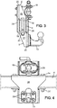
- FIGS. 1 and 2 illustrate at different angles a hitch assembly to be mounted at the rear of a traction vehicle not shown.
- the hitch assembly comprises a drawbar 4, a first part, hereinafter referred to as a top bracket 6, a second part subsequently referred to as the lower bracket 8, a standard ball hitch 14, a clevis hitch 16 as well as means for fixing these various elements.
- the drawbar 4 is formed here of a tubular section section, for example rectangular but other types of profile sections could be used.
- the drawbar 4 is preferably dimensioned to further provide a rear underrun function of the towing vehicle. It can be reported on a chassis of the vehicle or be an integral part of this frame and / or vehicle.
- the drawbar 4 is arranged horizontally, that is to say that its longitudinal axis is horizontal. As illustrated in the drawing, this bar has a rectangular section and it is assumed that this section is oriented so as to have a horizontal upper face, a lower face also horizontal and two vertical side faces connecting the upper face to the lower face.
- the chosen orientation is the "natural" orientation that corresponds to the orientation that is found when the drawbar 4 is mounted on a vehicle. This defines a relative concept up / down which will be used in the following description.
- FIG 5 proposes for example to fix said bar to frame side members.
- a fixing assembly in the illustrated embodiment, comprises a mounting flange 9 formed of an angled plate having at one of its ends frame mounting means which have holes 10 allowing a bolting on a spar 3.
- the figure 5 illustrates in exploded perspective attachment of a cheek 9 externally to a chassis spar.
- the cheek 9 has a welded support plate 11 which is perpendicular thereto and which is pierced with holes 12, thus forming means used to effect a tightening of the drawbar 4.
- the cheek 9 is fastened in parallel at the median plane of the vehicle so that the support plate 11 faces the rear of the vehicle. It is adapted to a recovery interface on the chassis, or an integration interface to it if necessary.
- Each fixing assembly (such as the one illustrated on the figure 5 ) further comprises two flanges 13 U-section bolted in the holes 12 of the corresponding support plate 11 so as to trap and tighten the drawbar 4.
- the latter can be positioned at will perpendicular to the median plane of the vehicle so that the coupling means (ball hitch 14 and clevis hitch 16) are in this median plane, regardless of the spacing of the frame members of the vehicle chassis.
- the fastening flanges 13 may take the form of one or more wire-section stirrups for example.
- the mounting flanges 9 are preferably sized so that the drawbar 4 is positioned to additionally provide the rear underrun function of the towing vehicle.
- the hitching means (ball hitch 14 and clevis hitch 16) are mounted on the hitching bar 4 by mounting means essentially comprising the upper bracket 6 and the lower bracket 8.
- the upper bracket 6 is similar to the lower bracket 8 in the preferred embodiment illustrated in the figures.
- Each bracket has a first wing 18 and a second wing 20. Ribs 21 are provided here between each first wing 18 and the corresponding second wing 20.
- the drawbar 4 is pierced on its horizontal faces with holes 22 for the vertical passage of bolts (screws 24 and nuts 24 '). Holes are also drilled in the first flange 18 of each bracket to fix each bracket by its first flange 18 on the drawbar 4. The first flanges 18 are then arranged horizontally. The screws 24 are long enough to completely cross the drawbar 4 and thus simultaneously ensure the fixing of the two squares on it.
- the brackets are positioned so that the second wings 20 extend vertically and are both parallel.
- the second wing 20 of the upper bracket 6 extends upwardly (thus away from the drawbar 4 and the lower bracket 8) and the second wing 20 of the lower bracket 8 s' extends downwards (thus moving away from the drawbar 4 and the upper bracket 6).
- the second wing 20 of the upper bracket 6 extends in a plane slightly forward of the drawbar 4 while the second wing 20 of the lower bracket 8 is slightly behind the drawbar 4.
- the forward / reverse orientation here corresponds to the orientation of the vehicle on which the drawbar 4 is mounted, the couplings (ball hitch 14 and clevis hitch 16 at the rear of the vehicle).
- Each bracket further comprises an additional face 26 extending in a vertical plane at height including the drawbar 4.
- the additional face 26 of the upper bracket 6 extends from the first flange 18 of this bracket down while the additional face 26 of the lower bracket 8 extends from the first flange 18 of this bracket upwards.
- each bracket thus has a Z-shape which can be obtained by two bends at 90 ° in two opposite directions and around two parallel fold lines, the fold lines corresponding substantially to two edges, so-called edges. longitudinals, the first wing 18.
- Each bracket can thus be obtained by cutting and folding a sheet. A welding operation can also be envisaged to weld the ribs 21.
- each additional face 26 preferably extends sufficiently to be able to face the second flange 20 of the other square and in contact with this second flange 20.
- oblong holes oriented vertically are provided . In the figures, these oblong holes are provided on the additional faces 26 but could also take place on the second wings 20.
- the screws 28 and the associated nuts 28 ' are also used for fixing the hitches.
- the clevis hitch 16 is fixed on the second flange 20 of the upper bracket 6. This second flange 20 is positioned forward with respect to the other second flange 20 (of the lower bracket 8).
- the ball hitch 14 is fixed on the second flange 20 of the lower bracket 8. It is noted here that the additional face 26 of the upper bracket 6 is interposed between the second flange 20 and the ball hitch 14.
- Mounting the hitch assembly on the drawbar 4 is quick and easy to achieve. First of all, fasten the two brackets on the drawbar with screws 24 and nuts 24 '. The brackets are then positioned and you just have to mount the hitches on the second wings of the brackets.
- the couplings are offset, the upper hitch (clevis hitch 16) being shifted forward relative to the lower hitch (ball hitch 14).
- This configuration minimizes the distance measured vertically (or altitude) between the hitches. Indeed, the space above the ball hitch 14 is entirely free and when a trailer comes to tackle this hitch, she is not bothered by the other team. Similarly, the ball hitch 14 does not interfere with the coupling of a trailer on the clevis hitch 16.
- the brackets can also act as reinforcement pieces whose inertia is appropriate according to the needs, in particular as a function of the load to be towed.
- the brackets can be made by folding as mentioned above but also for example by forging.
- a device provides two attachment points for two different coupling modes and this at different specific mounting heights while having a single mode of connection with a chassis of a towing vehicle.
- This provides the advantage for towing vehicles with only one towing beam location to be able to couple two types of trailers optimally (for example standard height "caravan” type hitch and non-standard altitude eye hitch and usually much higher).
- the described device has, on the one hand, a rectangular crossbar (the drawbar) and, secondly, a support that doubles the coupling fixings. These two parts are preferably linked by two bolts passing through the rectangular cross vertically from one side to the other.
- the clamping system with mounting flanges for fixing the drawbar on the vehicle, or more precisely the side rails of a vehicle in the mode described and illustrated, allows to perform continuously all the spacings of "plays "chassis” to fit any width of the towing vehicle frame and can be attached to the inner side or outer side of the side members that constitute the frame of the towing vehicle.
- the latter can fulfill in addition to its support function for the coupling device, the function of rear underrun device for the towing vehicle (height 100 mm, altitude of the lower surface to less than 550 mm from the ground, ends less than 100 mm from the width of the tires).
- the two through bolts determine the mounting position of the hitches so that they are located exactly on the longitudinal median plane of the towing vehicle.
- the device according to the invention has the advantage of allowing attachment by bolting an additional support to provide a fixing to an electrical coupling and a hook for the brake cable of relief, this at different positions to fit the trailer to tow.
- a device according to the invention makes it possible to adapt the relative position of two coupling modes so that it is compatible with the clearance zones required by the coupling standards of each of the coupling modes.
- the invention also makes it possible, by means of a clamping system similar to that of the rectangular crossbar, to simply provide a support for towing vehicle lights, speeding radars, a license plate or additional signage.
Description
La présente invention concerne un ensemble d'attelage double pour véhicule, notamment un véhicule automobile de traction.The present invention relates to a dual hitch assembly for a vehicle, in particular a traction motor vehicle.
Les ensembles d'attelage concernés par la présente invention sont plus particulièrement les ensembles comportant deux modes d'attelage distincts pour remorquer un véhicule tracté de manière à pouvoir atteler deux types de remorques différents.The hitch assemblies concerned by the present invention are more particularly the assemblies comprising two distinct coupling modes for towing a towed vehicle so as to be able to couple two different types of trailers.
Le document
Les documents
L'invention vise alors à fournir un ensemble d'attelage offrant deux modes d'attelage différents à des hauteurs de montage spécifiques tout en ayant un mode unique de liaison avec un châssis de véhicule de traction.The object of the invention is therefore to provide a hitch assembly offering two different coupling modes at specific mounting heights while having a unique mode of connection with a traction vehicle chassis.
L'invention a également pour but de fournir un tel ensemble d'attelage dans lequel la traction de la remorque s'effectue dans tous les cas dans le plan médian du véhicule. En conséquence, il se produit au freinage et à l'accélération un couple de torsion dans l'attelage. Ce dernier doit donc être conçu de manière à résister à ce couple cyclique, notamment en fatigue.The invention also aims to provide such a coupling assembly wherein the traction of the trailer is carried out in all cases in the median plane of the vehicle. As a result, there is a braking torque and acceleration torque in the hitch. The latter must be designed to withstand this cyclic torque, including fatigue.
Le document
Un but de la présente invention est de fournir un dispositif d'attelage compact de manière à limiter l'encombrement de l'attelage à l'arrière du véhicule auquel le dispositif d'attelage est destiné. La distance mesurée verticalement (ou l'altitude) entre un premier moyen d'attelage correspondant à un premier mode d'attelage et un second moyen d'attelage correspondant à un second mode d'attelage est de préférence réduite.An object of the present invention is to provide a compact hitch device so as to limit the size of the hitch at the rear of the vehicle to which the hitch device is intended. The vertically measured distance (or altitude) between a first coupling means corresponding to a first coupling mode and a second coupling means corresponding to a second coupling mode is preferably reduced.
Le dispositif d'attelage sera en outre de préférence facile à intégrer sur un véhicule et ergonomique.The coupling device will preferably further easy to integrate on a vehicle and ergonomic.
Avantageusement, l'invention permettra d'atteler au choix une remorque disposant d'un système d'attelage à boule normalisé, ou d'un système d'attelage non normalisé à chape.Advantageously, the invention will allow coupling to the choice of a trailer having a standard ball hitch system, or a non-standard hitch coupling system.
L'invention a également pour but de fournir un véhicule automobile de traction muni d'un ensemble d'attelage qui permette d'atteler au choix des remorques disposant de types d'attelage distincts.The invention also aims to provide a traction motor vehicle with a hitch assembly that allows to hitch the choice of trailers with different types of hitch.
À cet effet, elle propose un ensemble d'attelage double pour véhicule comportant des premiers moyens d'attelage, des seconds moyens d'attelage ainsi que deux équerres présentant chacune une première aile et une seconde aile.To this end, it proposes a double hitch assembly for a vehicle comprising first hitching means, second hitching means and two brackets each having a first wing and a second wing.
Selon la présente invention, les premières ailes sont fixées parallèlement l'une à l'autre en vis-à-vis ; les secondes ailes sont disposées de telle sorte qu'elles s'étendent à partir de la première aile correspondante en s'éloignant de l'autre équerre et de telle sorte que les secondes ailes soient parallèles mais décalées, et les premiers moyens d'attelage et les seconds moyens d'attelage sont fixés chacun sur une seconde aile d'une équerre.According to the present invention, the first wings are fixed parallel to each other vis-à-vis; the second wings are arranged such that they extend from the corresponding first wing away from the other square and so that the second wings are parallel but offset, and the first coupling means and the second coupling means are each fixed to a second wing of a square.
Cette nouvelle structure permet, grâce au décalage des secondes ailes, de ne plus avoir les moyens d'attelage l'un au-dessus de l'autre. De ce fait, les moyens d'attelage peuvent être rapprochés, permettant ainsi de réaliser un ensemble d'attelage compact.This new structure makes it possible, thanks to the offset of the second wings, to no longer have the coupling means one above the other. As a result, the hitching means can be brought together, thus making it possible to produce a compact hitch assembly.
Un ensemble d'attelage selon l'invention peut en outre comporter une barre d'attelage. Dans ce cas, les équerres sont par exemple boulonnées sur la barre d'attelage prise en sandwich entre les deux premières ailes des équerres. Par barre d'attelage, on entend tout longeron, poutre, de type traverse, à fonction d'attelage, rapporté sur le châssis du véhicule ou faisant partie intégrante de celui-ci. Le châssis peut être un châssis de type à longeron, ou mécano-soudé, tubulaire, ou de type châssis-coque, ou plus généralement toute structure portante de véhicule.A hitch assembly according to the invention may further comprise a drawbar. In this case, the brackets are for example bolted to the drawbar sandwiched between the first two wings of the brackets. "Drawbar" means any beam, beam, crosshead type, hitch function, attached to the chassis of the vehicle or making integral part of it. The frame may be a frame-type chassis, or mechanically welded, tubular, or chassis-hull type, or more generally any vehicle supporting structure.
Dans cette forme de réalisation intégrant une barre d'attelage, les équerres sont avantageusement fixées sur la barre d'attelage à l'aide de boulons traversant la barre d'attelage verticalement de part en part. Cette solution permet de simplifier le montage de l'ensemble selon l'invention.In this embodiment incorporating a drawbar, the brackets are advantageously fixed on the drawbar with bolts passing through the drawbar vertically from one side to the other. This solution simplifies the assembly of the assembly according to the invention.
Toujours dans le but de simplifier le montage de l'ensemble et d'augmenter ainsi l'ergonomie de cet ensemble, on prévoit avantageusement que les premiers moyens d'attelage et les seconds moyens d'attelage sont boulonnés sur les secondes ailes des équerres.Still with the aim of simplifying assembly of the assembly and thus increasing the ergonomics of this assembly, it is advantageously provided that the first coupling means and the second coupling means are bolted to the second wings of the brackets.
Une forme de réalisation avantageuse permettant d'obtenir une plus grande rigidité prévoit qu'au moins une équerre présente une face additionnelle s'étendant à partir de la première aile parallèlement à la seconde aile mais dans le sens opposé. On peut alors prévoir une fixation de cette face additionnelle sur une barre d'attelage ou autre dans une direction perpendiculaire à la fixation des premières ailes. Dans cette forme de réalisation, la première aile de ladite équerre comporte de préférence un premier bord à partir duquel s'étend la seconde aile ainsi qu'un second bord opposé au premier bord et à partir duquel s'étend la face additionnelle. L'équerre présente alors une forme en Z. Une alternative à cette forme de réalisation serait que la face additionnelle soit dans le prolongement de la seconde aile. On aurait alors une section en T de l'équerre, la base du T étant formée par la première aile.An advantageous embodiment for obtaining greater rigidity provides that at least one bracket has an additional face extending from the first wing parallel to the second wing but in the opposite direction. We can then provide a fixation of this additional face on a drawbar or other in a direction perpendicular to the attachment of the first wings. In this embodiment, the first wing of said bracket preferably comprises a first edge from which the second wing extends and a second edge opposite to the first edge and from which the additional face extends. The bracket then has a Z shape. An alternative to this embodiment is that the additional face is in the extension of the second wing. We would then have a T-section of the square, the base of the T being formed by the first wing.
Une forme de réalisation préférée prévoit que les deux équerres de l'ensemble d'attelage présentent une forme en Z. On a alors un ensemble d'attelage qui comporte deux équerres présentant chacune une face additionnelle s'étendant à partir de la première aile parallèlement à la seconde aile mais dans le sens opposé, la première aile de chaque équerre comportant un premier bord à partir duquel s'étend la seconde aile ainsi qu'un second bord opposé au premier bord et à partir duquel s'étend la face additionnelle. Une variante préférée prévoit que chaque face additionnelle se prolonge de manière à venir face à la seconde aile de l'autre équerre contre cette seconde aile. Une fixation entre les faces additionnelles et les secondes ailes des deux équerres peut alors être envisagée pour former un ensemble à la fois rigide et facile à monter. Un tel ensemble d'attelage peut alors prévoir, pour faciliter encore le montage, que des boulons assurent à la fois une fixation d'un moyen d'attelage sur une seconde aile d'une équerre et une liaison entre cette seconde aile et la face additionnelle de l'autre équerre.A preferred embodiment provides for the two brackets of the hitch assembly to have a Z-shape. There is then a hitch assembly which has two brackets each having an additional face extending from the first wing parallel to one another. to the second wing but in the opposite direction, the first wing of each bracket having a first edge from which extends the second wing and a second edge opposite the first edge and from which the additional face extends. A preferred variant provides that each additional face extends so as to face the second wing of the other bracket against this second wing. A fixing between the additional faces and the second wings of the two brackets can then be considered to form a set both rigid and easy to assemble. Such a hitch assembly can then provide, to further facilitate mounting, that bolts provide both a fixing of a coupling means on a second wing of a square and a connection between the second wing and the face additional the other square.
Lorsqu'un ensemble d'attelage selon la présente invention comporte également une barre d'attelage comme évoqué plus haut, on peut prévoir qu'il comporte en outre des moyens de fixation de la barre d'attelage, que lesdits moyens de fixation comprennent deux ensembles de fixation présentant chacun une joue de montage sensiblement perpendiculaire à la barre d'attelage, ladite joue de montage possédant, d'un côté, des moyens de montage à un châssis de véhicule automobile de traction et, d'un autre côté, des moyens de serrage sur la barre d'attelage, et que les moyens de serrage comprennent une plaque d'appui pour recevoir la barre d'attelage et une bride de serrage boulonnée sur la plaque d'appui.When a hitch assembly according to the present invention also comprises a drawbar as mentioned above, it may be provided that it further comprises means for fixing the drawbar, that said fixing means comprise two fastening assemblies each having a mounting flange substantially perpendicular to the drawbar, said mounting flange having on one side means for mounting to a traction motor vehicle frame and, on the other hand, clamping means on the drawbar, and that the clamping means comprises a support plate for receiving the drawbar and a clamping flange bolted to the support plate.
À titre d'exemple non limitatif, les premiers moyens d'attelage se présentent par exemple sous la forme d'un attelage à boule et/ou les seconds moyens d'attelage se présentent sous la forme d'un attelage à chape.By way of non-limiting example, the first coupling means are for example in the form of a ball coupling and / or the second coupling means are in the form of a clevis hitch.
Enfin, la présente invention concerne également un véhicule automobile de traction, caractérisé en ce qu'il comprend un ensemble d'attelage tel que décrit ci-dessus.Finally, the present invention also relates to a traction motor vehicle, characterized in that it comprises a coupling assembly as described above.
Des détails et avantages de la présente invention apparaitront mieux de la description qui suit, faite en référence au dessin schématique annexé sur lequel :
- La
figure 1 est une vue en perspective éclatée d'un ensemble d'attelage selon l'invention montré sous un premier angle, - La
figure 2 est une vue en perspective éclatée du même ensemble mais montré sous un angle différent, - La
figure 3 est une vue de côté de l'ensemble d'attelage desfigures 1 et 2 en position montée, - La
figure 4 illustre une vue de face de l'ensemble monté de lafigure 3 , et - La
figure 5 illustre un exemple de montage d'une barre d'attelage telle celle illustrée sur les figures précédentes sur un véhicule.
- The
figure 1 is an exploded perspective view of a coupling assembly according to the invention shown at a first angle, - The
figure 2 is an exploded perspective view of the same set but shown from a different angle, - The
figure 3 is a side view of the hitch assembly ofFigures 1 and 2 in mounted position, - The
figure 4 illustrates a front view of the mounted assembly of thefigure 3 , and - The
figure 5 illustrates an example of mounting a drawbar such as that illustrated in the previous figures on a vehicle.
Les
L'ensemble d'attelage comporte une barre d'attelage 4, une première pièce appelée par la suite équerre supérieure 6, une seconde pièce appelée par la suite équerre inférieure 8, un attelage à boule 14 normalisé, un attelage à chape 16 ainsi que des moyens de fixation de ces divers éléments.The hitch assembly comprises a
La barre d'attelage 4 est formée ici d'un profilé à section tubulaire, par exemple rectangulaire mais d'autres types de sections de profilés pourraient être utilisés. La barre d'attelage 4 est de préférence dimensionnée pour assurer en outre une fonction anti-encastrement arrière du véhicule de traction. Elle peut être rapportée sur un châssis du véhicule ou bien faire partie intégrante de ce châssis et/ou de ce véhicule.The
Pour la suite de la description, on suppose que la barre d'attelage 4 est disposée horizontalement, c'est-à-dire que son axe longitudinal est à l'horizontale. Comme illustré sur le dessin, cette barre a une section rectangulaire et on suppose que cette section est orientée de manière à présenter une face supérieure horizontale, une face inférieure également horizontale ainsi que deux faces latérales verticales reliant la face supérieure à la face inférieure. L'orientation choisie est l'orientation "naturelle" qui correspond à l'orientation que l'on retrouve lorsque la barre d'attelage 4 est montée sur un véhicule. On définit ainsi une notion relative haut/bas qui sera utilisée dans la suite de la description.For the rest of the description, it is assumed that the
Dans le cas du montage de la barre d'attelage 4 sur un châssis de véhicule, la
Chaque ensemble de fixation (tel celui illustré sur la
Les joues 9 de montage sont de préférence dimensionnées de manière que la barre d'attelage 4 soit positionnée pour assurer en outre la fonction anti-encastrement arrière du véhicule tracteur.The mounting flanges 9 are preferably sized so that the
Les moyens d'attelage (attelage à boule 14 et attelage à chape 16) sont montés sur la barre d'attelage 4 par des moyens de montage comportant essentiellement l'équerre supérieure 6 et l'équerre inférieure 8.The hitching means (
L'équerre supérieure 6 est similaire à l'équerre inférieure 8 dans la forme de réalisation préférée illustrée sur les figures. Chaque équerre présente une première aile 18 et une seconde aile 20. Des nervures 21 sont prévues ici entre chaque première aile 18 et la seconde aile 20 correspondante. La barre d'attelage 4 est percée sur ses faces horizontales de trous 22 pour le passage vertical de boulons (vis 24 et écrous 24'). Des trous sont aussi percés dans la première aile 18 de chaque équerre permettant de fixer chaque équerre par sa première aile 18 sur la barre d'attelage 4. Les premières ailes 18 sont alors disposées horizontalement. Les vis 24 sont assez longues pour traverser entièrement la barre d'attelage 4 et assurer ainsi simultanément la fixation des deux équerres sur celle-ci.The
Les équerres sont positionnées de telle manière que les secondes ailes 20 s'étendent verticalement et soient toutes deux parallèles. La seconde aile 20 de l'équerre supérieure 6 s'étend vers le haut (en s'éloignant donc de la barre d'attelage 4 et de l'équerre inférieure 8) et la seconde aile 20 de l'équerre inférieure 8 s'étend vers le bas (en s'éloignant donc de la barre d'attelage 4 et de l'équerre supérieure 6). Comme on peut le voir sur la
Chaque équerre comporte en outre une face additionnelle 26 s'étendant dans un plan vertical à hauteur notamment de la barre d'attelage 4. Ainsi, la face additionnelle 26 de l'équerre supérieure 6 s'étend à partir de la première aile 18 de cette équerre vers le bas tandis que la face additionnelle 26 de l'équerre inférieure 8 s'étend à partir de la première aile 18 de cette équerre vers le haut.Each bracket further comprises an
Dans une forme de réalisation préférée, chaque équerre présente ainsi une forme en Z qui peut être obtenue par deux pliages à 90° dans deux sens opposés et autour de deux lignes de pliages parallèles, les lignes de pliages correspondant sensiblement à deux bords, dits bords longitudinaux, de la première aile 18. Chaque équerre peut ainsi être obtenue par découpe et pliage d'une tôle. Une opération de soudure peut aussi être envisagée pour venir souder les nervures 21.In a preferred embodiment, each bracket thus has a Z-shape which can be obtained by two bends at 90 ° in two opposite directions and around two parallel fold lines, the fold lines corresponding substantially to two edges, so-called edges. longitudinals, the
Dans cette forme de réalisation, on prévoit avantageusement que chaque face additionnelle 26 s'étend de préférence suffisamment pour pouvoir venir se trouver face à la seconde aile 20 de l'autre équerre et au contact de cette seconde aile 20. En fixant alors les faces additionnelles 26 aux secondes ailes 20, on forme avec les deux équerres un ensemble très rigide, quasiment indéformable. Cet ensemble présente entre les premières ailes 18 et les faces additionnelles 26 un logement parallélépipédique qui reçoit la barre d'attelage 4.In this embodiment, it is advantageously provided that each
Pour la fixation des faces additionnelles 26 avec les secondes ailes 20, il est prévu d'utiliser quatre boulons (quatre vis 28 et quatre écrous 28') par fixation. Des trous sont prévus à cet effet à la fois dans les faces additionnelles 26 et dans les secondes ailes 20. Pour pouvoir adapter la taille du logement recevant la barre d'attelage 4 à la taille de cette dernière, des trous oblongs orientés verticalement sont prévus. Sur les figures, ces trous oblongs sont prévus sur les faces additionnelles 26 mais pourraient également prendre place sur les secondes ailes 20.For attachment of the additional faces 26 with the
Avantageusement, les vis 28 et les écrous 28' associés sont également utilisés pour la fixation des attelages. L'attelage à chape 16 est fixé sur la seconde aile 20 de l'équerre supérieure 6. Cette seconde aile 20 est positionnée en avant par rapport à l'autre seconde aile 20 (de l'équerre inférieure 8). L'attelage à boule 14 est fixé sur la seconde aile 20 de l'équerre inférieure 8. On remarque ici que la face additionnelle 26 de l'équerre supérieure 6 s'interpose entre la seconde aile 20 et l'attelage à boule 14.Advantageously, the
On peut également utiliser une (ou des) vis 28 et un (ou des) écrou(s) 28' pour la fixation d'une platine (non représentée mais illustrée par exemple sur la figure 7A de
Le montage de l'ensemble d'attelage sur la barre d'attelage 4 est simple et rapide à réaliser. Il suffit de tout d'abord venir fixer à l'aide des vis 24 et écrous 24' les deux équerres sur la barre d'attelage. Les équerres sont alors positionnées et il suffit de venir monter les attelages sur les secondes ailes des équerres.Mounting the hitch assembly on the
Comme on peut le voir au mieux sur la
Les équerres peuvent assurer également le rôle de pièces de renfort dont l'inertie est appropriée selon les besoins, notamment en fonction de la charge à tracter. Les équerres peuvent être réalisées par pliage comme évoqué plus haut mais aussi par exemple par forgeage.The brackets can also act as reinforcement pieces whose inertia is appropriate according to the needs, in particular as a function of the load to be towed. The brackets can be made by folding as mentioned above but also for example by forging.
Comme il ressort de la description qui précède, un dispositif selon la présente invention permet d'offrir deux points de fixation pour deux modes d'attelage différents et ceci à des hauteurs de montage spécifiques différentes tout en ayant un mode unique de liaison avec un châssis d'un véhicule tracteur. Cela procure l'avantage aux véhicules tracteurs pourvus d'un seul emplacement pour traverse remorquante de pouvoir atteler de façon optimale deux types de remorques (par exemple attelage à boule "type caravane" à altitude normalisée et attelage à oeil à altitude non normalisée et usuellement beaucoup plus haute).As is apparent from the foregoing description, a device according to the present invention provides two attachment points for two different coupling modes and this at different specific mounting heights while having a single mode of connection with a chassis of a towing vehicle. This provides the advantage for towing vehicles with only one towing beam location to be able to couple two types of trailers optimally (for example standard height "caravan" type hitch and non-standard altitude eye hitch and usually much higher).
Le dispositif décrit présente, d'une part, une traverse rectangulaire (la barre d'attelage) et, d'autre part, un support qui dédouble les fixations d'attelage. Ces deux pièces sont liées de préférence par deux boulons traversant la traverse rectangulaire verticalement de part en part.The described device has, on the one hand, a rectangular crossbar (the drawbar) and, secondly, a support that doubles the coupling fixings. These two parts are preferably linked by two bolts passing through the rectangular cross vertically from one side to the other.
Le système de bridage avec des joues de montage pour la fixation de la barre d'attelage sur le véhicule, ou plus précisément des longerons d'un véhicule dans le mode décrit et illustré, permet de réaliser de manière continue tous les entraxes de "joue de châssis" afin de s'adapter à n'importe quel largeur de châssis de véhicule tracteur et peut se fixer aussi bien côté intérieur ou côté extérieur des longerons qui constituent le châssis du véhicule tracteur.The clamping system with mounting flanges for fixing the drawbar on the vehicle, or more precisely the side rails of a vehicle in the mode described and illustrated, allows to perform continuously all the spacings of "plays "chassis" to fit any width of the towing vehicle frame and can be attached to the inner side or outer side of the side members that constitute the frame of the towing vehicle.
En adaptant les dimensions de la traverse rectangulaire, cette dernière peur remplir en plus de sa fonction de support pour le dispositif d'attelage, la fonction de dispositif anti-encastrement arrière pour le véhicule tracteur (hauteur 100 mm, altitude de la surface inférieure à moins 550 mm du sol, extrémités à moins de 100 mm de la largeur des pneumatiques).By adapting the dimensions of the rectangular crossmember, the latter can fulfill in addition to its support function for the coupling device, the function of rear underrun device for the towing vehicle (height 100 mm, altitude of the lower surface to less than 550 mm from the ground, ends less than 100 mm from the width of the tires).
Dans le dispositif décrit ci-dessus, les deux boulons traversants déterminent la position de montage des attelages pour qu'ils se situent exactement sur le plan médian longitudinal du véhicule tracteur.In the device described above, the two through bolts determine the mounting position of the hitches so that they are located exactly on the longitudinal median plane of the towing vehicle.
Comme évoqué plus haut, le dispositif selon l'invention présente l'avantage de permettre une fixation par boulonnage d'un support supplémentaire permettant d'offrir une fixation à une prise électrique d'attelage et d'un crochet pour le câble de frein de secours, ceci à différentes positions pour s'adapter à la remorque à tracter.As mentioned above, the device according to the invention has the advantage of allowing attachment by bolting an additional support to provide a fixing to an electrical coupling and a hook for the brake cable of relief, this at different positions to fit the trailer to tow.
Un dispositif selon l'invention permet d'adapter la position relative de deux modes d'attelage pour qu'elle soit compatible avec des zones de dégagement exigées par les normes d'attelage de chacun des modes d'attelage.A device according to the invention makes it possible to adapt the relative position of two coupling modes so that it is compatible with the clearance zones required by the coupling standards of each of the coupling modes.
L'invention permet aussi grâce à un système de bridage similaire à celui de la traverse rectangulaire de réaliser simplement un support pour des feux du véhicule tracteur, des radars de reculs, une plaque d'immatriculation ou une signalisation complémentaire.The invention also makes it possible, by means of a clamping system similar to that of the rectangular crossbar, to simply provide a support for towing vehicle lights, speeding radars, a license plate or additional signage.
On a ainsi un système très simple, modulable et répondant aux exigences techniques d'un attelage. Ce système est en outre compact et facile à mettre en oeuvre.We thus have a very simple system, flexible and meeting the technical requirements of a hitch. This system is also compact and easy to implement.
Bien entendu, la présente invention ne se limite pas à la forme de réalisation préférée décrite ci-dessus à titre d'exemple non limitatif et aux variantes évoquées. Elle concerne également toutes les variantes de réalisation à la portée de l'homme du métier dans le cadre des revendications ci-après.Of course, the present invention is not limited to the preferred embodiment described above by way of non-limiting example and the variants mentioned. It also relates to all the variants within the scope of those skilled in the art within the scope of the claims below.
Claims (12)
- Double hitch assembly for a vehicle comprising first hitching means (14), second hitching means (16) and two angle brackets (6, 8), each of which has a first flange (18) and a second flange (20),
characterised in that the first flanges (18) are secured parallel to and facing one another,
in that the second flanges (20) are positioned such that they extend from the first corresponding flange (18) in a direction away from the other angle bracket and such that the second flanges (20) are parallel but offset, and
in that the first hitching means (14) and the second hitching means (16) are each secured to a second flange (20) of an angle bracket. - Hitch assembly according to claim 1, characterised in that the angle brackets (6, 8) are bolted onto a draw bar (4) sandwiched between the two first flanges of the angle brackets (6, 8).
- Hitch assembly according to claim 2, characterised in that the angle brackets (6, 8) are secured to the draw bar (4) using bolts (24, 24') passing vertically through the draw bar (4) end to end.
- Hitch assembly according to one of claims 1 to 3, characterised in that the first hitch means (14) and the second hitch means (16) are bolted onto the second flanges (20) of the angle brackets (6, 8).
- Hitch assembly according to any of claims 1 to 4, characterised in that at least one angle bracket (6, 8) has an additional face (26) extending from the first flange (18) parallel to the second flange (20), but in the opposite direction thereto.
- Hitch assembly according to claim 5, characterised in that the first flange (18) of said angle bracket comprises a first edge from which extends the second flange (20), in addition to a second edge opposite the first edge and from which extends the additional face (26).
- Hitch assembly according to one of claims 1 to 6, characterised in that it comprises two angle brackets (6, 8), each having an additional face (26) extending from the first flange (18) parallel to the second flange (20), however in the opposite direction thereto, the first flange of each angle bracket (6, 8) comprising a first edge from which extends the second flange (20), in addition to a second edge opposite the first edge and from which extends the additional face (26), and in that each additional face (26) extends such that it comes to face the second flange (20) of the other angle bracket against said second flange (20).
- Hitch assembly according to claim 7, characterised in that the bolts (28, 28') serve both to secure a hitching means onto a second flange (20) of an angle bracket (6, 8) and to create a link between said second flange (20) and the additional face (26) of the other angle bracket.
- Hitch assembly according to either claim 2 or claim 3, characterised in that it further comprises fastening means for securing the draw bar (4), in that said fastening means comprise two fastening assemblies, each of which having an assembly wall (9) substantially perpendicular to the draw bar, said assembly wall having, on one side thereof, assembly means (10) for assembly to a frame of a tractive motor vehicle and, on the other side thereof, clamping means (11, 13) for clamping to the draw bar (4), and in that the clamping means comprise a bearing plate (11) for receiving the draw bar (4) and a clamp (13) bolted to the bearing plate (11).
- Hitch assembly according to one of claims 1 to 9, characterised in that the first hitching means are present in the form of a ball mount (14).
- Hitch assembly according to one of claims 1 to 10, characterised in that the second hitching means are present in the form of a clevis mount (16).
- Tractive motor vehicle characterised in that it comprises a hitch assembly according to one of the previous claims.
Applications Claiming Priority (1)
| Application Number | Priority Date | Filing Date | Title |
|---|---|---|---|
| FR1354810A FR3006243B1 (en) | 2013-05-28 | 2013-05-28 | DUAL COUPLING ASSEMBLY FOR VEHICLE |
Publications (2)
| Publication Number | Publication Date |
|---|---|
| EP2808184A1 EP2808184A1 (en) | 2014-12-03 |
| EP2808184B1 true EP2808184B1 (en) | 2018-06-06 |
Family
ID=49209497
Family Applications (1)
| Application Number | Title | Priority Date | Filing Date |
|---|---|---|---|
| EP14170316.5A Active EP2808184B1 (en) | 2013-05-28 | 2014-05-28 | Double hitch assembly for a vehicle |
Country Status (2)
| Country | Link |
|---|---|
| EP (1) | EP2808184B1 (en) |
| FR (1) | FR3006243B1 (en) |
Families Citing this family (2)
| Publication number | Priority date | Publication date | Assignee | Title |
|---|---|---|---|---|
| DE202015104491U1 (en) | 2015-08-25 | 2016-11-28 | Alois Kober Gmbh | drawbar |
| DE102016124562A1 (en) * | 2016-09-30 | 2018-04-05 | Westfalia-Automotive Gmbh | Trailer coupling with a tie rod |
Family Cites Families (5)
| Publication number | Priority date | Publication date | Assignee | Title |
|---|---|---|---|---|
| GB1405499A (en) | 1972-11-08 | 1975-09-10 | Coker K G | Towing hitches |
| NL7901094A (en) * | 1979-02-12 | 1980-08-14 | Hendrikus Jan Zwaantinus Klein | Towing vehicle coupling unit - has vertical rotary lockable plate with ball hitch and eyes at opposite ends |
| GB2167365A (en) | 1984-11-27 | 1986-05-29 | Kenneth George Coker | A trailer coupling hitch |
| FR2740079B1 (en) * | 1995-10-23 | 1998-01-16 | Sarl Etablissements Goutorbe & | HITCHING DEVICE BETWEEN TWO ROLLING PARTS OF A HIPPOMOBILE VEHICLE IN PARTICULAR |
| FR2983125B1 (en) * | 2011-11-25 | 2014-05-02 | Ur Ben | COUPLING ASSEMBLY FOR AUTOMOBILE TRACTION VEHICLE |
-
2013
- 2013-05-28 FR FR1354810A patent/FR3006243B1/en not_active Expired - Fee Related
-
2014
- 2014-05-28 EP EP14170316.5A patent/EP2808184B1/en active Active
Non-Patent Citations (1)
| Title |
|---|
| None * |
Also Published As
| Publication number | Publication date |
|---|---|
| EP2808184A1 (en) | 2014-12-03 |
| FR3006243A1 (en) | 2014-12-05 |
| FR3006243B1 (en) | 2016-08-26 |
Similar Documents
| Publication | Publication Date | Title |
|---|---|---|
| EP2596966B1 (en) | Hitching assembly for a towing motor vehicle | |
| FR3090505A1 (en) | VEHICLE SIDE PART STRUCTURE | |
| EP2808184B1 (en) | Double hitch assembly for a vehicle | |
| EP3261860B1 (en) | Hitching system | |
| EP3459767B1 (en) | Arrangement for attaching a transversal bar to a motor vehicle body | |
| FR2474988A1 (en) | MODULAR CHASSIS, ESPECIALLY FOR CARAVANS OR OTHER ROAD TRAILERS | |
| EP2424768B1 (en) | Device for attaching an engine cradle to a vehicle body understructure, use of said attachment device, and resulting vehicle | |
| EP3050758B1 (en) | Structural subassembly of a motor vehicle and method for mounting said subassembly | |
| EP2836378B1 (en) | Attachment of a towing device with a force distribution support | |
| FR2979093A1 (en) | Supporting structure for supporting electric drive powertrain of electric car, has backlash adjuster compensating play between connecting and bonding surfaces of intermediate frame, and bolts locking adjuster in play compensation position | |
| EP3119620B1 (en) | System for coupling a range of carriers with a swivel hook fixed to the rear structure of a motor vehicle | |
| FR2976904A1 (en) | Device for fastening cabin on chassis of lorry, has spacer provided inside interface of cabin and equipped with axial positioning units inserted into holes in plates of mounting interface, where spacer is designed as single-piece metal part | |
| FR2956064A1 (en) | COUPLING DEVICE FOR A MOTOR VEHICLE AND VEHICLE EQUIPPED WITH SUCH A COUPLING DEVICE. | |
| FR3118607A1 (en) | HITCHING DEVICE WITH PRE-HOLDING PROTUBER(S), FOR ONE VEHICLE | |
| EP3152100B1 (en) | Assembly for holding a spare wheel in an underbody, vehicle provided with such an assembly, method for producing such an assembly and method for mounting such an assembly on a vehicle | |
| FR3014809A1 (en) | REAR CHASSIS STRUCTURE OF A VEHICLE HAS LONGERONNETS CONNECTED TO THE OTHER BY A RELEASABLE SUPPORT OF ONE OF THE LONGERONNETS IN CASE OF REAR SHOCK | |
| WO2015075333A1 (en) | Vehicle structure with metal mounting for motor vehicle drawbar eye and vehicle provided with such a structure | |
| FR3140016A1 (en) | Chassis for a motor vehicle comprising connecting arms intended to be integral with a coupling crossmember | |
| EP4240637A1 (en) | Front structure of a motor vehicle | |
| WO2024062165A1 (en) | Electric vehicle having a rear axle with a deformable crossmember and an aerodynamic deflector support | |
| FR2931419A1 (en) | Adjustable bumper mounting device i.e. bumper armature, for vehicle, has vertical branches including support units supported on fixation plates that fix crosspiece of bumper on body of vehicle, for avoiding tilting of device | |
| EP1610005A1 (en) | Clip for the attachment of a screw to parts of an automobile | |
| FR2935952A1 (en) | Accessory e.g. door-ladder, fixing assembly for trailer hitched to e.g. lorry, has cooperation units permitting cooperation of end fitting with screwing unit to engender locking of accessory on chassis column of trailer along axis of post | |
| FR2899557A3 (en) | Technical front face assembling arrangement for motor vehicle, has upper crosspiece and two side rails connected by lower crosspiece, where technical front face is mounted on lower crosspiece by terminals carried by front face | |
| EP1319532A1 (en) | Arrangement for fastening on a hollow beam of a hitch element to a towing or anchoring member of a motor vehicle |
Legal Events
| Date | Code | Title | Description |
|---|---|---|---|
| PUAI | Public reference made under article 153(3) epc to a published international application that has entered the european phase |
Free format text: ORIGINAL CODE: 0009012 |
|
| 17P | Request for examination filed |
Effective date: 20140528 |
|
| AK | Designated contracting states |
Kind code of ref document: A1 Designated state(s): AL AT BE BG CH CY CZ DE DK EE ES FI FR GB GR HR HU IE IS IT LI LT LU LV MC MK MT NL NO PL PT RO RS SE SI SK SM TR |
|
| AX | Request for extension of the european patent |
Extension state: BA ME |
|
| R17P | Request for examination filed (corrected) |
Effective date: 20150529 |
|
| RBV | Designated contracting states (corrected) |
Designated state(s): AL AT BE BG CH CY CZ DE DK EE ES FI FR GB GR HR HU IE IS IT LI LT LU LV MC MK MT NL NO PL PT RO RS SE SI SK SM TR |
|
| GRAP | Despatch of communication of intention to grant a patent |
Free format text: ORIGINAL CODE: EPIDOSNIGR1 |
|
| STAA | Information on the status of an ep patent application or granted ep patent |
Free format text: STATUS: GRANT OF PATENT IS INTENDED |
|
| INTG | Intention to grant announced |
Effective date: 20171122 |
|
| GRAS | Grant fee paid |
Free format text: ORIGINAL CODE: EPIDOSNIGR3 |
|
| GRAJ | Information related to disapproval of communication of intention to grant by the applicant or resumption of examination proceedings by the epo deleted |
Free format text: ORIGINAL CODE: EPIDOSDIGR1 |
|
| GRAL | Information related to payment of fee for publishing/printing deleted |
Free format text: ORIGINAL CODE: EPIDOSDIGR3 |
|
| STAA | Information on the status of an ep patent application or granted ep patent |
Free format text: STATUS: REQUEST FOR EXAMINATION WAS MADE |
|
| RIN1 | Information on inventor provided before grant (corrected) |
Inventor name: FLOTTES, JOEL Inventor name: GAFFARD, BENJAMIN Inventor name: CAVALLARI, PHILIPPE Inventor name: FERAL, JEAN-MARC |
|
| INTC | Intention to grant announced (deleted) | ||
| GRAJ | Information related to disapproval of communication of intention to grant by the applicant or resumption of examination proceedings by the epo deleted |
Free format text: ORIGINAL CODE: EPIDOSDIGR1 |
|
| GRAR | Information related to intention to grant a patent recorded |
Free format text: ORIGINAL CODE: EPIDOSNIGR71 |
|
| STAA | Information on the status of an ep patent application or granted ep patent |
Free format text: STATUS: GRANT OF PATENT IS INTENDED |
|
| GRAA | (expected) grant |
Free format text: ORIGINAL CODE: 0009210 |
|
| STAA | Information on the status of an ep patent application or granted ep patent |
Free format text: STATUS: THE PATENT HAS BEEN GRANTED |
|
| AK | Designated contracting states |
Kind code of ref document: B1 Designated state(s): AL AT BE BG CH CY CZ DE DK EE ES FI FR GB GR HR HU IE IS IT LI LT LU LV MC MK MT NL NO PL PT RO RS SE SI SK SM TR |
|
| INTG | Intention to grant announced |
Effective date: 20180427 |
|
| REG | Reference to a national code |
Ref country code: GB Ref legal event code: FG4D Free format text: NOT ENGLISH |
|
| RIN1 | Information on inventor provided before grant (corrected) |
Inventor name: GAFFARD, BENJAMIN Inventor name: FLOTTES, JOEL Inventor name: FERAL, JEAN-MARC Inventor name: CAVALLARI, PHILIPPE |
|
| REG | Reference to a national code |
Ref country code: CH Ref legal event code: EP Ref country code: AT Ref legal event code: REF Ref document number: 1005667 Country of ref document: AT Kind code of ref document: T Effective date: 20180615 |
|
| REG | Reference to a national code |
Ref country code: IE Ref legal event code: FG4D Free format text: LANGUAGE OF EP DOCUMENT: FRENCH |
|
| REG | Reference to a national code |
Ref country code: DE Ref legal event code: R096 Ref document number: 602014026561 Country of ref document: DE |
|
| REG | Reference to a national code |
Ref country code: NL Ref legal event code: MP Effective date: 20180606 |
|
| REG | Reference to a national code |
Ref country code: LT Ref legal event code: MG4D |
|
| PG25 | Lapsed in a contracting state [announced via postgrant information from national office to epo] |
Ref country code: BG Free format text: LAPSE BECAUSE OF FAILURE TO SUBMIT A TRANSLATION OF THE DESCRIPTION OR TO PAY THE FEE WITHIN THE PRESCRIBED TIME-LIMIT Effective date: 20180906 Ref country code: NO Free format text: LAPSE BECAUSE OF FAILURE TO SUBMIT A TRANSLATION OF THE DESCRIPTION OR TO PAY THE FEE WITHIN THE PRESCRIBED TIME-LIMIT Effective date: 20180906 Ref country code: FI Free format text: LAPSE BECAUSE OF FAILURE TO SUBMIT A TRANSLATION OF THE DESCRIPTION OR TO PAY THE FEE WITHIN THE PRESCRIBED TIME-LIMIT Effective date: 20180606 Ref country code: SE Free format text: LAPSE BECAUSE OF FAILURE TO SUBMIT A TRANSLATION OF THE DESCRIPTION OR TO PAY THE FEE WITHIN THE PRESCRIBED TIME-LIMIT Effective date: 20180606 Ref country code: CY Free format text: LAPSE BECAUSE OF FAILURE TO SUBMIT A TRANSLATION OF THE DESCRIPTION OR TO PAY THE FEE WITHIN THE PRESCRIBED TIME-LIMIT Effective date: 20180606 Ref country code: LT Free format text: LAPSE BECAUSE OF FAILURE TO SUBMIT A TRANSLATION OF THE DESCRIPTION OR TO PAY THE FEE WITHIN THE PRESCRIBED TIME-LIMIT Effective date: 20180606 Ref country code: ES Free format text: LAPSE BECAUSE OF FAILURE TO SUBMIT A TRANSLATION OF THE DESCRIPTION OR TO PAY THE FEE WITHIN THE PRESCRIBED TIME-LIMIT Effective date: 20180606 |
|
| PG25 | Lapsed in a contracting state [announced via postgrant information from national office to epo] |
Ref country code: LV Free format text: LAPSE BECAUSE OF FAILURE TO SUBMIT A TRANSLATION OF THE DESCRIPTION OR TO PAY THE FEE WITHIN THE PRESCRIBED TIME-LIMIT Effective date: 20180606 Ref country code: HR Free format text: LAPSE BECAUSE OF FAILURE TO SUBMIT A TRANSLATION OF THE DESCRIPTION OR TO PAY THE FEE WITHIN THE PRESCRIBED TIME-LIMIT Effective date: 20180606 Ref country code: GR Free format text: LAPSE BECAUSE OF FAILURE TO SUBMIT A TRANSLATION OF THE DESCRIPTION OR TO PAY THE FEE WITHIN THE PRESCRIBED TIME-LIMIT Effective date: 20180907 Ref country code: RS Free format text: LAPSE BECAUSE OF FAILURE TO SUBMIT A TRANSLATION OF THE DESCRIPTION OR TO PAY THE FEE WITHIN THE PRESCRIBED TIME-LIMIT Effective date: 20180606 |
|
| REG | Reference to a national code |
Ref country code: AT Ref legal event code: MK05 Ref document number: 1005667 Country of ref document: AT Kind code of ref document: T Effective date: 20180606 |
|
| PG25 | Lapsed in a contracting state [announced via postgrant information from national office to epo] |
Ref country code: NL Free format text: LAPSE BECAUSE OF FAILURE TO SUBMIT A TRANSLATION OF THE DESCRIPTION OR TO PAY THE FEE WITHIN THE PRESCRIBED TIME-LIMIT Effective date: 20180606 |
|
| PG25 | Lapsed in a contracting state [announced via postgrant information from national office to epo] |
Ref country code: EE Free format text: LAPSE BECAUSE OF FAILURE TO SUBMIT A TRANSLATION OF THE DESCRIPTION OR TO PAY THE FEE WITHIN THE PRESCRIBED TIME-LIMIT Effective date: 20180606 Ref country code: PL Free format text: LAPSE BECAUSE OF FAILURE TO SUBMIT A TRANSLATION OF THE DESCRIPTION OR TO PAY THE FEE WITHIN THE PRESCRIBED TIME-LIMIT Effective date: 20180606 Ref country code: RO Free format text: LAPSE BECAUSE OF FAILURE TO SUBMIT A TRANSLATION OF THE DESCRIPTION OR TO PAY THE FEE WITHIN THE PRESCRIBED TIME-LIMIT Effective date: 20180606 Ref country code: AT Free format text: LAPSE BECAUSE OF FAILURE TO SUBMIT A TRANSLATION OF THE DESCRIPTION OR TO PAY THE FEE WITHIN THE PRESCRIBED TIME-LIMIT Effective date: 20180606 Ref country code: IS Free format text: LAPSE BECAUSE OF FAILURE TO SUBMIT A TRANSLATION OF THE DESCRIPTION OR TO PAY THE FEE WITHIN THE PRESCRIBED TIME-LIMIT Effective date: 20181006 Ref country code: CZ Free format text: LAPSE BECAUSE OF FAILURE TO SUBMIT A TRANSLATION OF THE DESCRIPTION OR TO PAY THE FEE WITHIN THE PRESCRIBED TIME-LIMIT Effective date: 20180606 Ref country code: SK Free format text: LAPSE BECAUSE OF FAILURE TO SUBMIT A TRANSLATION OF THE DESCRIPTION OR TO PAY THE FEE WITHIN THE PRESCRIBED TIME-LIMIT Effective date: 20180606 |
|
| PG25 | Lapsed in a contracting state [announced via postgrant information from national office to epo] |
Ref country code: SM Free format text: LAPSE BECAUSE OF FAILURE TO SUBMIT A TRANSLATION OF THE DESCRIPTION OR TO PAY THE FEE WITHIN THE PRESCRIBED TIME-LIMIT Effective date: 20180606 Ref country code: IT Free format text: LAPSE BECAUSE OF FAILURE TO SUBMIT A TRANSLATION OF THE DESCRIPTION OR TO PAY THE FEE WITHIN THE PRESCRIBED TIME-LIMIT Effective date: 20180606 |
|
| REG | Reference to a national code |
Ref country code: DE Ref legal event code: R097 Ref document number: 602014026561 Country of ref document: DE |
|
| PLBE | No opposition filed within time limit |
Free format text: ORIGINAL CODE: 0009261 |
|
| STAA | Information on the status of an ep patent application or granted ep patent |
Free format text: STATUS: NO OPPOSITION FILED WITHIN TIME LIMIT |
|
| 26N | No opposition filed |
Effective date: 20190307 |
|
| PG25 | Lapsed in a contracting state [announced via postgrant information from national office to epo] |
Ref country code: DK Free format text: LAPSE BECAUSE OF FAILURE TO SUBMIT A TRANSLATION OF THE DESCRIPTION OR TO PAY THE FEE WITHIN THE PRESCRIBED TIME-LIMIT Effective date: 20180606 Ref country code: SI Free format text: LAPSE BECAUSE OF FAILURE TO SUBMIT A TRANSLATION OF THE DESCRIPTION OR TO PAY THE FEE WITHIN THE PRESCRIBED TIME-LIMIT Effective date: 20180606 |
|
| PG25 | Lapsed in a contracting state [announced via postgrant information from national office to epo] |
Ref country code: AL Free format text: LAPSE BECAUSE OF FAILURE TO SUBMIT A TRANSLATION OF THE DESCRIPTION OR TO PAY THE FEE WITHIN THE PRESCRIBED TIME-LIMIT Effective date: 20180606 |
|
| PG25 | Lapsed in a contracting state [announced via postgrant information from national office to epo] |
Ref country code: MC Free format text: LAPSE BECAUSE OF FAILURE TO SUBMIT A TRANSLATION OF THE DESCRIPTION OR TO PAY THE FEE WITHIN THE PRESCRIBED TIME-LIMIT Effective date: 20180606 |
|
| PG25 | Lapsed in a contracting state [announced via postgrant information from national office to epo] |
Ref country code: LU Free format text: LAPSE BECAUSE OF NON-PAYMENT OF DUE FEES Effective date: 20190528 |
|
| PG25 | Lapsed in a contracting state [announced via postgrant information from national office to epo] |
Ref country code: TR Free format text: LAPSE BECAUSE OF FAILURE TO SUBMIT A TRANSLATION OF THE DESCRIPTION OR TO PAY THE FEE WITHIN THE PRESCRIBED TIME-LIMIT Effective date: 20180606 |
|
| PG25 | Lapsed in a contracting state [announced via postgrant information from national office to epo] |
Ref country code: IE Free format text: LAPSE BECAUSE OF NON-PAYMENT OF DUE FEES Effective date: 20190528 |
|
| PG25 | Lapsed in a contracting state [announced via postgrant information from national office to epo] |
Ref country code: PT Free format text: LAPSE BECAUSE OF FAILURE TO SUBMIT A TRANSLATION OF THE DESCRIPTION OR TO PAY THE FEE WITHIN THE PRESCRIBED TIME-LIMIT Effective date: 20181008 |
|
| PG25 | Lapsed in a contracting state [announced via postgrant information from national office to epo] |
Ref country code: MT Free format text: LAPSE BECAUSE OF FAILURE TO SUBMIT A TRANSLATION OF THE DESCRIPTION OR TO PAY THE FEE WITHIN THE PRESCRIBED TIME-LIMIT Effective date: 20180606 Ref country code: HU Free format text: LAPSE BECAUSE OF FAILURE TO SUBMIT A TRANSLATION OF THE DESCRIPTION OR TO PAY THE FEE WITHIN THE PRESCRIBED TIME-LIMIT; INVALID AB INITIO Effective date: 20140528 |
|
| PG25 | Lapsed in a contracting state [announced via postgrant information from national office to epo] |
Ref country code: MK Free format text: LAPSE BECAUSE OF FAILURE TO SUBMIT A TRANSLATION OF THE DESCRIPTION OR TO PAY THE FEE WITHIN THE PRESCRIBED TIME-LIMIT Effective date: 20180606 |
|
| PGFP | Annual fee paid to national office [announced via postgrant information from national office to epo] |
Ref country code: FR Payment date: 20230517 Year of fee payment: 10 Ref country code: DE Payment date: 20230613 Year of fee payment: 10 Ref country code: CH Payment date: 20230701 Year of fee payment: 10 |
|
| PGFP | Annual fee paid to national office [announced via postgrant information from national office to epo] |
Ref country code: BE Payment date: 20230526 Year of fee payment: 10 |
|
| PGFP | Annual fee paid to national office [announced via postgrant information from national office to epo] |
Ref country code: GB Payment date: 20230620 Year of fee payment: 10 |