EP2808088A1 - Fluid dispensing gun - Google Patents
Fluid dispensing gun Download PDFInfo
- Publication number
- EP2808088A1 EP2808088A1 EP13170020.5A EP13170020A EP2808088A1 EP 2808088 A1 EP2808088 A1 EP 2808088A1 EP 13170020 A EP13170020 A EP 13170020A EP 2808088 A1 EP2808088 A1 EP 2808088A1
- Authority
- EP
- European Patent Office
- Prior art keywords
- dosing nozzle
- needle
- gun
- followed
- fluid dispensing
- Prior art date
- Legal status (The legal status is an assumption and is not a legal conclusion. Google has not performed a legal analysis and makes no representation as to the accuracy of the status listed.)
- Granted
Links
Images



Classifications
-
- B—PERFORMING OPERATIONS; TRANSPORTING
- B65—CONVEYING; PACKING; STORING; HANDLING THIN OR FILAMENTARY MATERIAL
- B65D—CONTAINERS FOR STORAGE OR TRANSPORT OF ARTICLES OR MATERIALS, e.g. BAGS, BARRELS, BOTTLES, BOXES, CANS, CARTONS, CRATES, DRUMS, JARS, TANKS, HOPPERS, FORWARDING CONTAINERS; ACCESSORIES, CLOSURES, OR FITTINGS THEREFOR; PACKAGING ELEMENTS; PACKAGES
- B65D83/00—Containers or packages with special means for dispensing contents
- B65D83/14—Containers for dispensing liquid or semi-liquid contents by internal gaseous pressure, i.e. aerosol containers comprising propellant
- B65D83/16—Actuating means
- B65D83/164—Actuators comprising a manually operated valve and being attachable to the aerosol container, e.g. downstream a valve fitted to the container; Actuators associated to container valves with valve seats located outside the aerosol container
-
- B—PERFORMING OPERATIONS; TRANSPORTING
- B05—SPRAYING OR ATOMISING IN GENERAL; APPLYING FLUENT MATERIALS TO SURFACES, IN GENERAL
- B05B—SPRAYING APPARATUS; ATOMISING APPARATUS; NOZZLES
- B05B1/00—Nozzles, spray heads or other outlets, with or without auxiliary devices such as valves, heating means
- B05B1/30—Nozzles, spray heads or other outlets, with or without auxiliary devices such as valves, heating means designed to control volume of flow, e.g. with adjustable passages
- B05B1/3033—Nozzles, spray heads or other outlets, with or without auxiliary devices such as valves, heating means designed to control volume of flow, e.g. with adjustable passages the control being effected by relative coaxial longitudinal movement of the controlling element and the spray head
- B05B1/304—Nozzles, spray heads or other outlets, with or without auxiliary devices such as valves, heating means designed to control volume of flow, e.g. with adjustable passages the control being effected by relative coaxial longitudinal movement of the controlling element and the spray head the controlling element being a lift valve
- B05B1/3046—Nozzles, spray heads or other outlets, with or without auxiliary devices such as valves, heating means designed to control volume of flow, e.g. with adjustable passages the control being effected by relative coaxial longitudinal movement of the controlling element and the spray head the controlling element being a lift valve the valve element, e.g. a needle, co-operating with a valve seat located downstream of the valve element and its actuating means, generally in the proximity of the outlet orifice
-
- B—PERFORMING OPERATIONS; TRANSPORTING
- B05—SPRAYING OR ATOMISING IN GENERAL; APPLYING FLUENT MATERIALS TO SURFACES, IN GENERAL
- B05B—SPRAYING APPARATUS; ATOMISING APPARATUS; NOZZLES
- B05B12/00—Arrangements for controlling delivery; Arrangements for controlling the spray area
- B05B12/002—Manually-actuated controlling means, e.g. push buttons, levers or triggers
-
- B—PERFORMING OPERATIONS; TRANSPORTING
- B05—SPRAYING OR ATOMISING IN GENERAL; APPLYING FLUENT MATERIALS TO SURFACES, IN GENERAL
- B05B—SPRAYING APPARATUS; ATOMISING APPARATUS; NOZZLES
- B05B12/00—Arrangements for controlling delivery; Arrangements for controlling the spray area
- B05B12/004—Arrangements for controlling delivery; Arrangements for controlling the spray area comprising sensors for monitoring the delivery, e.g. by displaying the sensed value or generating an alarm
- B05B12/006—Pressure or flow rate sensors
- B05B12/008—Pressure or flow rate sensors integrated in or attached to a discharge apparatus, e.g. a spray gun
-
- B—PERFORMING OPERATIONS; TRANSPORTING
- B05—SPRAYING OR ATOMISING IN GENERAL; APPLYING FLUENT MATERIALS TO SURFACES, IN GENERAL
- B05B—SPRAYING APPARATUS; ATOMISING APPARATUS; NOZZLES
- B05B9/00—Spraying apparatus for discharge of liquids or other fluent material, without essentially mixing with gas or vapour
- B05B9/03—Spraying apparatus for discharge of liquids or other fluent material, without essentially mixing with gas or vapour characterised by means for supplying liquid or other fluent material
- B05B9/04—Spraying apparatus for discharge of liquids or other fluent material, without essentially mixing with gas or vapour characterised by means for supplying liquid or other fluent material with pressurised or compressible container; with pump
- B05B9/08—Apparatus to be carried on or by a person, e.g. of knapsack type
- B05B9/0894—Gun with a container which, in normal use, is located above the gun
-
- B—PERFORMING OPERATIONS; TRANSPORTING
- B05—SPRAYING OR ATOMISING IN GENERAL; APPLYING FLUENT MATERIALS TO SURFACES, IN GENERAL
- B05B—SPRAYING APPARATUS; ATOMISING APPARATUS; NOZZLES
- B05B1/00—Nozzles, spray heads or other outlets, with or without auxiliary devices such as valves, heating means
- B05B1/14—Nozzles, spray heads or other outlets, with or without auxiliary devices such as valves, heating means with multiple outlet openings; with strainers in or outside the outlet opening
Definitions
- the invention concerns a fluid dispensing gun comprising a dispensing tube with a dosing nozzle, a spring-loaded needle which is co-axially moveable in the dispensing tube for opening and closing the dosing nozzle, a trigger for actuating said needle in order to open the dosing nozzle and to dispense the fluid, regulating means for regulating the degree of opening of the outlet of the dosing nozzle and coupling means for coupling a pressurized can to the gun.
- Fluid dispensing guns are used for dispensing one or two component polyurethane (PU) foam systems, adhesives, sealants, etc.
- PU polyurethane
- a fluid dispensing gun for foams, adhesives and sealants comprising a dispensing tube and a trigger for actuating a gun needle able to open the end of said dispensing tube for dispensing the fluid which may be coupled to a pressurized can is known from EP 1 650 140 A1 .
- the object of the present invention is therefore to provide a better regulation and control of the output rate of the fluid dispensing gun.
- the inside of the dosing nozzle has a first cylindrical area, followed by a first conical area, followed by a second cylindrical area, followed by a second conical area and ends in the outlet of the dosing nozzle with a third cylindrical area.
- the invention is based on the fact that in current dispensing guns in which the dosing nozzle has a first cylindrical area, followed by a conical area and ends in the dosing nozzle with a second cylindrical area the ratio between the needle travel and the foam output is insufficient since with a small needle travel the output is highly increased.
- the new design of the dosing nozzle overcomes this drawback. With this new design of the inner area of the dosing nozzle, it is easier to regulate the output rate of the dispensing gun.
- a further embodiment of the invention consists in the fact that means for visual feedback of the current degree of opening of the outlet of the dosing nozzle are provided.
- This embodiment concerns the control of the output rate and can be applied independently from the new design of the dosing nozzle, but also be combined with it.
- the user can only consider the degree he has activated the regulating means for regulating the degree of opening of the dosing nozzle in order to have a vague idea of the current output rate.
- the output rate can hardly be adapted to the current needs.
- With a visual feedback the user is able to see at any moment how the output rate is regulated.
- the means for visual feedback are designed as position indicators which show the current co-axial position of the needle within the dispensing tube.
- optical means can be coupled to the needle or parts linked to it in order to show the current co-axial position of the needle within the dispensing tube.
- the position indicators are in form of a window or a plurality of windows provided in the housing of the gun and the needle or a part linked to it is provided with markers which appear in the windows in function of the co-axial position of the needle within the dispensing tube.
- the part linked to the needle can be e.g. the regulating means which is generally in form of a back screw.
- This back screw can be provided with a slope which appears in the window or the windows provided in the wall of the gun showing the degree of opening of the dosing nozzle.
- means for acoustic and/or haptic feedback of the current output rate are provided.
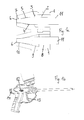
- the inside of the dosing nozzle (1) according to the present invention has a first cylindrical area (2), followed by a first conical area (3), followed by a second cylindrical area (4), followed by a second conical area (5) and ends in the outlet (6) of the dosing nozzle (1) with a third cylindrical area (7).
- the dosing nozzle (1) of a current dispensing gun (lower view of the figures) has a first cylindrical area (8), followed by a conical area (9) and ends in the dosing nozzle (6) with a second cylindrical area (10).
- the design of the needle (11) is unchanged.
- the current position of the needle defining the output rate is shown by position indicators are in form of a plurality of windows (12) provided in the housing (17) of the gun and the needle or a part linked to it is provided with markers which appear in the windows in function of the co-axial position of the needle within the dispensing tube.
- the four white windows of Fig. 1b correspond to the closed position
- the one black window of Fig. 2b corresponds to low output
- the two black windows of Fig. 3b correspond to middle output
- the three black windows of Fig. 4b correspond to high output
- the four black windows of Fig. 5b correspond to maximum output.
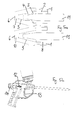
- Fig. 6a shows an overview of the assembly and Fig. 6b shows a detail view of the rear part of the needle (11) and of the back screw (14).
- the needle (11) can be activated by pushing the trigger (13).
- the needle (11) has a front part (11a) and a rear part (11b) which are coupled together.
- the needle (11) is loaded by a spring (12) pushing on the rear part (11b) of the needle (11).
- a back screw (14) is linked to the rear part (11b) of the needle (11) and is provided with a thread (15) cooperating with a corresponding thread (16) of the housing (17) of the gun.
- the lead or pitch on the back screw (14) is 3 mm which means that if the back screw (14) is turned slightly less than 360° (which is the maximum), a needle travel of 3 mm is achieved. Since a needle travel of about 4 mm is required for a satisfying regulation of the fluid output, a slope (19) is provided on the rear part (11b) of the needle (11) as shown in Fig. 6b .
- a second slope (18) provided on the back screw (14) gives visual feedback of the current output rate since it appears in the windows (12) of the housing (17) as explained above concerning Figures 1b , 2b , 3b , 4b and 5b .
- the back screw (14) with the slope (18) at its end is shown in detail in Figures 7a and 7b .
Landscapes
- Chemical & Material Sciences (AREA)
- Analytical Chemistry (AREA)
- Dispersion Chemistry (AREA)
- Engineering & Computer Science (AREA)
- Mechanical Engineering (AREA)
- Physics & Mathematics (AREA)
- Fluid Mechanics (AREA)
- Coating Apparatus (AREA)
Abstract
Description
- The invention concerns a fluid dispensing gun comprising a dispensing tube with a dosing nozzle, a spring-loaded needle which is co-axially moveable in the dispensing tube for opening and closing the dosing nozzle, a trigger for actuating said needle in order to open the dosing nozzle and to dispense the fluid, regulating means for regulating the degree of opening of the outlet of the dosing nozzle and coupling means for coupling a pressurized can to the gun.
- Fluid dispensing guns are used for dispensing one or two component polyurethane (PU) foam systems, adhesives, sealants, etc.
- A fluid dispensing gun for foams, adhesives and sealants comprising a dispensing tube and a trigger for actuating a gun needle able to open the end of said dispensing tube for dispensing the fluid which may be coupled to a pressurized can is known from
EP 1 650 140 A1 - A major drawback of presently available fluid dispensing guns lies in the fact that the output rate cannot be very precisely regulated and controlled.
- The object of the present invention is therefore to provide a better regulation and control of the output rate of the fluid dispensing gun.
- This object is achieved according to the present invention in that the inside of the dosing nozzle has a first cylindrical area, followed by a first conical area, followed by a second cylindrical area, followed by a second conical area and ends in the outlet of the dosing nozzle with a third cylindrical area.
- The invention is based on the fact that in current dispensing guns in which the dosing nozzle has a first cylindrical area, followed by a conical area and ends in the dosing nozzle with a second cylindrical area the ratio between the needle travel and the foam output is insufficient since with a small needle travel the output is highly increased. The new design of the dosing nozzle overcomes this drawback. With this new design of the inner area of the dosing nozzle, it is easier to regulate the output rate of the dispensing gun.
- A further embodiment of the invention consists in the fact that means for visual feedback of the current degree of opening of the outlet of the dosing nozzle are provided.
- This embodiment concerns the control of the output rate and can be applied independently from the new design of the dosing nozzle, but also be combined with it. In currently available fluid dispensing guns, the user can only consider the degree he has activated the regulating means for regulating the degree of opening of the dosing nozzle in order to have a vague idea of the current output rate. Combined with the fact that in current fluid dispensing guns a small needle travel leads to a high increase of the output rate, the output rate can hardly be adapted to the current needs. With a visual feedback, the user is able to see at any moment how the output rate is regulated.
- It is within the scope of the present invention that the means for visual feedback are designed as position indicators which show the current co-axial position of the needle within the dispensing tube.
- Since the needle opens and closes the dosing nozzle and defines the output rate, optical means can be coupled to the needle or parts linked to it in order to show the current co-axial position of the needle within the dispensing tube.
- In this context, it is possible that the position indicators are in form of a window or a plurality of windows provided in the housing of the gun and the needle or a part linked to it is provided with markers which appear in the windows in function of the co-axial position of the needle within the dispensing tube.
- The part linked to the needle can be e.g. the regulating means which is generally in form of a back screw. This back screw can be provided with a slope which appears in the window or the windows provided in the wall of the gun showing the degree of opening of the dosing nozzle. As alternative or complementary embodiment of the present invention, means for acoustic and/or haptic feedback of the current output rate are provided.
- In this context, it is possible to have a snap fixed on the needle which provokes a snapping noise at each progression of the needle. This may help users in a dark environment to estimate the current dosing nozzle rate. It is also possible to fix on the needle a protrusion which can be felt at the outside of the gun by the user. In function of the position of the protrusion within a window, the user can estimate the current output rate.
- In the following, execution examples of the invention are explained in detail with reference to the figures.
- Fig. 1a
- a comparative representation of a dosing nozzle according to the invention and of a dosing nozzle according to the prior art with 0 mm needle travel,
- Fig. 1b
- the visual feedback for the user corresponding to the position of
Fig. 1a , - Fig. 2a
- a comparative representation of a dosing nozzle according to the invention and of a dosing nozzle according to the prior art with 1 mm needle travel,
- Fig. 2b
- the visual feedback for the user corresponding to the position of
Fig. 2a , - Fig. 3a
- a comparative representation of a dosing nozzle according to the invention and of a dosing nozzle according to the prior art with 2 mm needle travel,
- Fig. 3b
- the visual feedback for the user corresponding to the position of
Fig. 3 a, - Fig. 4a
- a comparative representation of a dosing nozzle according to the invention and of a dosing nozzle according to the prior art with 3 mm needle travel,
- Fig. 4b
- the visual feedback for the user corresponding to the position of
Fig. 4a , - Fig. 5a
- a comparative representation of a dosing nozzle according to the invention and of a dosing nozzle according to the prior art with 4 mm needle travel,
- Fig. 5b
- the visual feedback for the user corresponding to the position of
Fig. 5a , - Fig. 6a
- an overview of the assembly,
- Fig. 6b
- a detail view of the rear part of the needle and of the back screw,
- Fig. 7a
- a perspective view of the back screw and
- Fig. 7b
- a side view of the back screw.
- As shown in
Fig. 1a ,2a ,3a ,4a and5a , the inside of the dosing nozzle (1) according to the present invention (upper view of the figures) has a first cylindrical area (2), followed by a first conical area (3), followed by a second cylindrical area (4), followed by a second conical area (5) and ends in the outlet (6) of the dosing nozzle (1) with a third cylindrical area (7). The dosing nozzle (1) of a current dispensing gun (lower view of the figures) has a first cylindrical area (8), followed by a conical area (9) and ends in the dosing nozzle (6) with a second cylindrical area (10). The design of the needle (11) is unchanged. - Tests have shown that the ratio between the needle travel and the foam output rate is much better with the design of the dosing nozzle (1) according to the present invention because the ratio between the needle travel and the output is less important and more linear. Therefore, it is easier to regulate the output rate of the fluid dispensing gun.
- As shown in
Fig. 1b ,2b ,3b ,4b and5b , the current position of the needle defining the output rate is shown by position indicators are in form of a plurality of windows (12) provided in the housing (17) of the gun and the needle or a part linked to it is provided with markers which appear in the windows in function of the co-axial position of the needle within the dispensing tube. The four white windows ofFig. 1b correspond to the closed position, the one black window ofFig. 2b corresponds to low output, the two black windows ofFig. 3b correspond to middle output, the three black windows ofFig. 4b correspond to high output and the four black windows ofFig. 5b correspond to maximum output. - Of course, it is possible to provide more or less windows or to visualize the output rate of the fluid dispensing gun in any other way.
-
Fig. 6a shows an overview of the assembly andFig. 6b shows a detail view of the rear part of the needle (11) and of the back screw (14). The needle (11) can be activated by pushing the trigger (13). The needle (11) has a front part (11a) and a rear part (11b) which are coupled together. The needle (11) is loaded by a spring (12) pushing on the rear part (11b) of the needle (11). A back screw (14) is linked to the rear part (11b) of the needle (11) and is provided with a thread (15) cooperating with a corresponding thread (16) of the housing (17) of the gun. Turning the end of the back screw (14) which is outside the housing of the fluid dispensing gun makes the needle travel co-axially within the housing (17) and regulates the degree of opening of the dosing nozzle (1). The lead or pitch on the back screw (14) is 3 mm which means that if the back screw (14) is turned slightly less than 360° (which is the maximum), a needle travel of 3 mm is achieved. Since a needle travel of about 4 mm is required for a satisfying regulation of the fluid output, a slope (19) is provided on the rear part (11b) of the needle (11) as shown inFig. 6b . - A second slope (18) provided on the back screw (14) gives visual feedback of the current output rate since it appears in the windows (12) of the housing (17) as explained above concerning
Figures 1b ,2b ,3b ,4b and5b . The back screw (14) with the slope (18) at its end is shown in detail inFigures 7a and 7b .
Claims (5)
- Fluid dispensing gun comprising a dispensing tube with a dosing nozzle (1), a spring-loaded needle (11) which is co-axially moveable in the dispensing tube for opening and closing the dosing nozzle (1), a trigger (13) for actuating said needle (11) in order to open the dosing nozzle (1) and to dispense the fluid, regulating means (14) for regulating the degree of opening of the outlet (6) of the dosing nozzle (1) and coupling means for coupling a pressurized can to the gun, characterized in that the inside of the dosing nozzle (1) has a first cylindrical area (2), followed by a first conical area (3), followed by a second cylindrical area (4), followed by a second conical area (5) and ends in the outlet (6) of the dosing nozzle (1) with a third cylindrical area (7).
- Fluid dispensing gun according to claim 1, characterized in that means for visual feedback of the current degree of opening of the outlet (6) of the dosing nozzle (1) are provided.
- Fluid dispensing gun according to claim 1 or to claim 2, characterized in that the means for visual feedback are designed as position indicators which show the current co-axial position of the needle (11) within the dispensing tube.
- Fluid dispensing gun according to one of the preceding claims, characterized in that the position indicators are in form of a window (12) or a plurality of windows (12) provided in the housing (17) of the gun and the needle (11) or a part linked to it is provided with markers which appear in the windows (12) in function of the co-axial position of the needle (11) within the dispensing tube.
- Fluid dispensing gun according to one of the preceding claims, characterized in that means for acoustic and/or haptic feedback of the current dosing nozzle rate are provided.
Priority Applications (2)
| Application Number | Priority Date | Filing Date | Title |
|---|---|---|---|
| PL13170020T PL2808088T3 (en) | 2013-05-31 | 2013-05-31 | Fluid dispensing gun |
| EP13170020.5A EP2808088B1 (en) | 2013-05-31 | 2013-05-31 | Fluid dispensing gun |
Applications Claiming Priority (1)
| Application Number | Priority Date | Filing Date | Title |
|---|---|---|---|
| EP13170020.5A EP2808088B1 (en) | 2013-05-31 | 2013-05-31 | Fluid dispensing gun |
Publications (2)
| Publication Number | Publication Date |
|---|---|
| EP2808088A1 true EP2808088A1 (en) | 2014-12-03 |
| EP2808088B1 EP2808088B1 (en) | 2020-09-09 |
Family
ID=48537835
Family Applications (1)
| Application Number | Title | Priority Date | Filing Date |
|---|---|---|---|
| EP13170020.5A Active EP2808088B1 (en) | 2013-05-31 | 2013-05-31 | Fluid dispensing gun |
Country Status (2)
| Country | Link |
|---|---|
| EP (1) | EP2808088B1 (en) |
| PL (1) | PL2808088T3 (en) |
Cited By (2)
| Publication number | Priority date | Publication date | Assignee | Title |
|---|---|---|---|---|
| WO2015065607A1 (en) * | 2013-10-31 | 2015-05-07 | Nordson Corporation | Dispensing module having a sealing zone and method for dispensing an adhesive |
| WO2019175423A1 (en) | 2018-03-16 | 2019-09-19 | Altachem N.V. | Fluid dispensing gun and method for dispensing 1k-polyurethane foam |
Citations (6)
| Publication number | Priority date | Publication date | Assignee | Title |
|---|---|---|---|---|
| DE20011470U1 (en) * | 2000-06-30 | 2001-11-15 | Sata-Farbspritztechnik GmbH & Co., 70806 Kornwestheim | Spray gun |
| WO2003022449A1 (en) * | 2001-09-06 | 2003-03-20 | Graco Minnesota Inc. | Voltage and current display for electrostatic spray gun |
| EP1650140A1 (en) | 2004-10-19 | 2006-04-26 | de Schrijver, Aster | Foam or fluid dispensing gun supplied by pressurised can |
| EP2055391A2 (en) * | 2007-10-31 | 2009-05-06 | Nordson Corporation | Improved spray gun trigger apparatus and methods |
| WO2011080028A1 (en) * | 2009-12-30 | 2011-07-07 | Robert Bosch Gmbh | Handheld spraying device |
| US20110168811A1 (en) * | 2008-07-23 | 2011-07-14 | Sata Gmbh & Co. Kg | Spray Gun With Paint Cartridge |
Family Cites Families (1)
| Publication number | Priority date | Publication date | Assignee | Title |
|---|---|---|---|---|
| CH670580A5 (en) * | 1987-04-16 | 1989-06-30 | Ehrensperger C Ag |
-
2013
- 2013-05-31 EP EP13170020.5A patent/EP2808088B1/en active Active
- 2013-05-31 PL PL13170020T patent/PL2808088T3/en unknown
Patent Citations (6)
| Publication number | Priority date | Publication date | Assignee | Title |
|---|---|---|---|---|
| DE20011470U1 (en) * | 2000-06-30 | 2001-11-15 | Sata-Farbspritztechnik GmbH & Co., 70806 Kornwestheim | Spray gun |
| WO2003022449A1 (en) * | 2001-09-06 | 2003-03-20 | Graco Minnesota Inc. | Voltage and current display for electrostatic spray gun |
| EP1650140A1 (en) | 2004-10-19 | 2006-04-26 | de Schrijver, Aster | Foam or fluid dispensing gun supplied by pressurised can |
| EP2055391A2 (en) * | 2007-10-31 | 2009-05-06 | Nordson Corporation | Improved spray gun trigger apparatus and methods |
| US20110168811A1 (en) * | 2008-07-23 | 2011-07-14 | Sata Gmbh & Co. Kg | Spray Gun With Paint Cartridge |
| WO2011080028A1 (en) * | 2009-12-30 | 2011-07-07 | Robert Bosch Gmbh | Handheld spraying device |
Cited By (7)
| Publication number | Priority date | Publication date | Assignee | Title |
|---|---|---|---|---|
| WO2015065607A1 (en) * | 2013-10-31 | 2015-05-07 | Nordson Corporation | Dispensing module having a sealing zone and method for dispensing an adhesive |
| US9108214B2 (en) | 2013-10-31 | 2015-08-18 | Nordson Corporation | Dispensing module having a sealing zone and method for dispensing an adhesive |
| US9475082B2 (en) | 2013-10-31 | 2016-10-25 | Nordson Corporation | Method for dispensing an adhesive |
| WO2019175423A1 (en) | 2018-03-16 | 2019-09-19 | Altachem N.V. | Fluid dispensing gun and method for dispensing 1k-polyurethane foam |
| CN111836764A (en) * | 2018-03-16 | 2020-10-27 | 阿尔塔谢姆股份有限公司 | Fluid Dispensing Gun and Method for Dispensing 1K-Polyurethane Foam |
| CN111836764B (en) * | 2018-03-16 | 2021-12-31 | 阿尔塔谢姆股份有限公司 | Fluid dispensing gun and method for dispensing 1K-polyurethane foam |
| US11801523B2 (en) | 2018-03-16 | 2023-10-31 | Altachem Nv | Fluid dispensing gun and method for dispensing 1K-polyurethane foam |
Also Published As
| Publication number | Publication date |
|---|---|
| PL2808088T3 (en) | 2021-01-11 |
| EP2808088B1 (en) | 2020-09-09 |
Similar Documents
| Publication | Publication Date | Title |
|---|---|---|
| EP2384819B1 (en) | Kitchen sink sprayer | |
| EP2808088B1 (en) | Fluid dispensing gun | |
| EA031642B1 (en) | Hinge device for doors, shutters or the like | |
| EP2851595B1 (en) | Tap group | |
| US9708800B2 (en) | Kitchen sink sprayer | |
| WO2015047758A3 (en) | Automatic self-dispensing accurate dose drug delivery syringes | |
| WO2016066344A1 (en) | Spray gun for a high-pressure cleaning appliance | |
| EP3147546A1 (en) | Device for opening, closing and regulating a flow rate for a faucet body of a bath or kitchen | |
| US11407248B2 (en) | Retractable nosecone writing instrument | |
| EP3557163A1 (en) | Refrigerator door body and refrigerator provided with same | |
| DE212015000261U1 (en) | Audible or noiseless switchable photoelectric switch | |
| GB2537209A (en) | A water saving mechanism with high flow volume in low pressure | |
| EP2713381B1 (en) | Push-button switch, selector switch, and fixing component therefor | |
| ES2956064T3 (en) | Control device for a vehicle | |
| US9790667B2 (en) | Push-activated tub spout | |
| DE102016100452A1 (en) | Faucet with pull-out spray | |
| CN112513397A (en) | Damper | |
| JP4732530B2 (en) | Operation lever mounting structure | |
| EP2735795B1 (en) | Gas tap for a cooking appliance | |
| KR20170053768A (en) | Nozzle assembly for bidet and bidet having the same | |
| KR20210051843A (en) | Fluid flow control damper | |
| WO2012015603A3 (en) | Leak-proof art instrument | |
| CN108784306B (en) | An installation structure and cooking appliance used to confirm whether the steam valve is installed in place | |
| JP6808171B2 (en) | Soap liquid supply device | |
| US7475834B2 (en) | Pistol nozzle |
Legal Events
| Date | Code | Title | Description |
|---|---|---|---|
| PUAI | Public reference made under article 153(3) epc to a published international application that has entered the european phase |
Free format text: ORIGINAL CODE: 0009012 |
|
| 17P | Request for examination filed |
Effective date: 20130531 |
|
| AK | Designated contracting states |
Kind code of ref document: A1 Designated state(s): AL AT BE BG CH CY CZ DE DK EE ES FI FR GB GR HR HU IE IS IT LI LT LU LV MC MK MT NL NO PL PT RO RS SE SI SK SM TR |
|
| AX | Request for extension of the european patent |
Extension state: BA ME |
|
| R17P | Request for examination filed (corrected) |
Effective date: 20150602 |
|
| RBV | Designated contracting states (corrected) |
Designated state(s): AL AT BE BG CH CY CZ DE DK EE ES FI FR GB GR HR HU IE IS IT LI LT LU LV MC MK MT NL NO PL PT RO RS SE SI SK SM TR |
|
| RAP1 | Party data changed (applicant data changed or rights of an application transferred) |
Owner name: ALTACHEM NV |
|
| STAA | Information on the status of an ep patent application or granted ep patent |
Free format text: STATUS: EXAMINATION IS IN PROGRESS |
|
| 17Q | First examination report despatched |
Effective date: 20181012 |
|
| GRAP | Despatch of communication of intention to grant a patent |
Free format text: ORIGINAL CODE: EPIDOSNIGR1 |
|
| STAA | Information on the status of an ep patent application or granted ep patent |
Free format text: STATUS: GRANT OF PATENT IS INTENDED |
|
| RIC1 | Information provided on ipc code assigned before grant |
Ipc: B05B 9/08 20060101ALI20200507BHEP Ipc: B05B 1/00 20060101ALI20200507BHEP Ipc: B65D 83/20 20060101ALI20200507BHEP Ipc: B05B 1/30 20060101AFI20200507BHEP Ipc: B05B 7/12 20060101ALI20200507BHEP Ipc: B05B 12/00 20180101ALI20200507BHEP Ipc: B05B 1/14 20060101ALN20200507BHEP |
|
| INTG | Intention to grant announced |
Effective date: 20200525 |
|
| GRAS | Grant fee paid |
Free format text: ORIGINAL CODE: EPIDOSNIGR3 |
|
| GRAA | (expected) grant |
Free format text: ORIGINAL CODE: 0009210 |
|
| STAA | Information on the status of an ep patent application or granted ep patent |
Free format text: STATUS: THE PATENT HAS BEEN GRANTED |
|
| AK | Designated contracting states |
Kind code of ref document: B1 Designated state(s): AL AT BE BG CH CY CZ DE DK EE ES FI FR GB GR HR HU IE IS IT LI LT LU LV MC MK MT NL NO PL PT RO RS SE SI SK SM TR |
|
| REG | Reference to a national code |
Ref country code: GB Ref legal event code: FG4D |
|
| REG | Reference to a national code |
Ref country code: AT Ref legal event code: REF Ref document number: 1310895 Country of ref document: AT Kind code of ref document: T Effective date: 20200915 Ref country code: CH Ref legal event code: EP |
|
| REG | Reference to a national code |
Ref country code: DE Ref legal event code: R096 Ref document number: 602013072314 Country of ref document: DE |
|
| REG | Reference to a national code |
Ref country code: IE Ref legal event code: FG4D |
|
| REG | Reference to a national code |
Ref country code: NL Ref legal event code: FP |
|
| REG | Reference to a national code |
Ref country code: EE Ref legal event code: FG4A Ref document number: E019911 Country of ref document: EE Effective date: 20201021 |
|
| REG | Reference to a national code |
Ref country code: LT Ref legal event code: MG4D |
|
| PG25 | Lapsed in a contracting state [announced via postgrant information from national office to epo] |
Ref country code: BG Free format text: LAPSE BECAUSE OF FAILURE TO SUBMIT A TRANSLATION OF THE DESCRIPTION OR TO PAY THE FEE WITHIN THE PRESCRIBED TIME-LIMIT Effective date: 20201209 Ref country code: SE Free format text: LAPSE BECAUSE OF FAILURE TO SUBMIT A TRANSLATION OF THE DESCRIPTION OR TO PAY THE FEE WITHIN THE PRESCRIBED TIME-LIMIT Effective date: 20200909 Ref country code: NO Free format text: LAPSE BECAUSE OF FAILURE TO SUBMIT A TRANSLATION OF THE DESCRIPTION OR TO PAY THE FEE WITHIN THE PRESCRIBED TIME-LIMIT Effective date: 20201209 Ref country code: GR Free format text: LAPSE BECAUSE OF FAILURE TO SUBMIT A TRANSLATION OF THE DESCRIPTION OR TO PAY THE FEE WITHIN THE PRESCRIBED TIME-LIMIT Effective date: 20201210 Ref country code: FI Free format text: LAPSE BECAUSE OF FAILURE TO SUBMIT A TRANSLATION OF THE DESCRIPTION OR TO PAY THE FEE WITHIN THE PRESCRIBED TIME-LIMIT Effective date: 20200909 Ref country code: HR Free format text: LAPSE BECAUSE OF FAILURE TO SUBMIT A TRANSLATION OF THE DESCRIPTION OR TO PAY THE FEE WITHIN THE PRESCRIBED TIME-LIMIT Effective date: 20200909 Ref country code: LT Free format text: LAPSE BECAUSE OF FAILURE TO SUBMIT A TRANSLATION OF THE DESCRIPTION OR TO PAY THE FEE WITHIN THE PRESCRIBED TIME-LIMIT Effective date: 20200909 |
|
| REG | Reference to a national code |
Ref country code: AT Ref legal event code: MK05 Ref document number: 1310895 Country of ref document: AT Kind code of ref document: T Effective date: 20200909 |
|
| PG25 | Lapsed in a contracting state [announced via postgrant information from national office to epo] |
Ref country code: LV Free format text: LAPSE BECAUSE OF FAILURE TO SUBMIT A TRANSLATION OF THE DESCRIPTION OR TO PAY THE FEE WITHIN THE PRESCRIBED TIME-LIMIT Effective date: 20200909 Ref country code: RS Free format text: LAPSE BECAUSE OF FAILURE TO SUBMIT A TRANSLATION OF THE DESCRIPTION OR TO PAY THE FEE WITHIN THE PRESCRIBED TIME-LIMIT Effective date: 20200909 |
|
| PG25 | Lapsed in a contracting state [announced via postgrant information from national office to epo] |
Ref country code: SM Free format text: LAPSE BECAUSE OF FAILURE TO SUBMIT A TRANSLATION OF THE DESCRIPTION OR TO PAY THE FEE WITHIN THE PRESCRIBED TIME-LIMIT Effective date: 20200909 Ref country code: PT Free format text: LAPSE BECAUSE OF FAILURE TO SUBMIT A TRANSLATION OF THE DESCRIPTION OR TO PAY THE FEE WITHIN THE PRESCRIBED TIME-LIMIT Effective date: 20210111 Ref country code: CZ Free format text: LAPSE BECAUSE OF FAILURE TO SUBMIT A TRANSLATION OF THE DESCRIPTION OR TO PAY THE FEE WITHIN THE PRESCRIBED TIME-LIMIT Effective date: 20200909 |
|
| PG25 | Lapsed in a contracting state [announced via postgrant information from national office to epo] |
Ref country code: AL Free format text: LAPSE BECAUSE OF FAILURE TO SUBMIT A TRANSLATION OF THE DESCRIPTION OR TO PAY THE FEE WITHIN THE PRESCRIBED TIME-LIMIT Effective date: 20200909 Ref country code: AT Free format text: LAPSE BECAUSE OF FAILURE TO SUBMIT A TRANSLATION OF THE DESCRIPTION OR TO PAY THE FEE WITHIN THE PRESCRIBED TIME-LIMIT Effective date: 20200909 Ref country code: ES Free format text: LAPSE BECAUSE OF FAILURE TO SUBMIT A TRANSLATION OF THE DESCRIPTION OR TO PAY THE FEE WITHIN THE PRESCRIBED TIME-LIMIT Effective date: 20200909 Ref country code: IS Free format text: LAPSE BECAUSE OF FAILURE TO SUBMIT A TRANSLATION OF THE DESCRIPTION OR TO PAY THE FEE WITHIN THE PRESCRIBED TIME-LIMIT Effective date: 20210109 |
|
| REG | Reference to a national code |
Ref country code: DE Ref legal event code: R097 Ref document number: 602013072314 Country of ref document: DE |
|
| PG25 | Lapsed in a contracting state [announced via postgrant information from national office to epo] |
Ref country code: SK Free format text: LAPSE BECAUSE OF FAILURE TO SUBMIT A TRANSLATION OF THE DESCRIPTION OR TO PAY THE FEE WITHIN THE PRESCRIBED TIME-LIMIT Effective date: 20200909 |
|
| PLBE | No opposition filed within time limit |
Free format text: ORIGINAL CODE: 0009261 |
|
| STAA | Information on the status of an ep patent application or granted ep patent |
Free format text: STATUS: NO OPPOSITION FILED WITHIN TIME LIMIT |
|
| PGFP | Annual fee paid to national office [announced via postgrant information from national office to epo] |
Ref country code: FR Payment date: 20210511 Year of fee payment: 9 Ref country code: NL Payment date: 20210519 Year of fee payment: 9 |
|
| 26N | No opposition filed |
Effective date: 20210610 |
|
| PG25 | Lapsed in a contracting state [announced via postgrant information from national office to epo] |
Ref country code: SI Free format text: LAPSE BECAUSE OF FAILURE TO SUBMIT A TRANSLATION OF THE DESCRIPTION OR TO PAY THE FEE WITHIN THE PRESCRIBED TIME-LIMIT Effective date: 20200909 Ref country code: DK Free format text: LAPSE BECAUSE OF FAILURE TO SUBMIT A TRANSLATION OF THE DESCRIPTION OR TO PAY THE FEE WITHIN THE PRESCRIBED TIME-LIMIT Effective date: 20200909 |
|
| PGFP | Annual fee paid to national office [announced via postgrant information from national office to epo] |
Ref country code: TR Payment date: 20210526 Year of fee payment: 9 |
|
| PG25 | Lapsed in a contracting state [announced via postgrant information from national office to epo] |
Ref country code: IT Free format text: LAPSE BECAUSE OF FAILURE TO SUBMIT A TRANSLATION OF THE DESCRIPTION OR TO PAY THE FEE WITHIN THE PRESCRIBED TIME-LIMIT Effective date: 20200909 |
|
| REG | Reference to a national code |
Ref country code: EE Ref legal event code: MM4A Ref document number: E019911 Country of ref document: EE Effective date: 20210531 |
|
| REG | Reference to a national code |
Ref country code: CH Ref legal event code: PL |
|
| GBPC | Gb: european patent ceased through non-payment of renewal fee |
Effective date: 20210531 |
|
| PG25 | Lapsed in a contracting state [announced via postgrant information from national office to epo] |
Ref country code: EE Free format text: LAPSE BECAUSE OF NON-PAYMENT OF DUE FEES Effective date: 20210531 Ref country code: RO Free format text: LAPSE BECAUSE OF NON-PAYMENT OF DUE FEES Effective date: 20200909 Ref country code: LI Free format text: LAPSE BECAUSE OF NON-PAYMENT OF DUE FEES Effective date: 20210531 Ref country code: MC Free format text: LAPSE BECAUSE OF FAILURE TO SUBMIT A TRANSLATION OF THE DESCRIPTION OR TO PAY THE FEE WITHIN THE PRESCRIBED TIME-LIMIT Effective date: 20200909 Ref country code: LU Free format text: LAPSE BECAUSE OF NON-PAYMENT OF DUE FEES Effective date: 20210531 Ref country code: CH Free format text: LAPSE BECAUSE OF NON-PAYMENT OF DUE FEES Effective date: 20210531 |
|
| PG25 | Lapsed in a contracting state [announced via postgrant information from national office to epo] |
Ref country code: IE Free format text: LAPSE BECAUSE OF NON-PAYMENT OF DUE FEES Effective date: 20210531 Ref country code: GB Free format text: LAPSE BECAUSE OF NON-PAYMENT OF DUE FEES Effective date: 20210531 |
|
| REG | Reference to a national code |
Ref country code: NL Ref legal event code: MM Effective date: 20220601 |
|
| PG25 | Lapsed in a contracting state [announced via postgrant information from national office to epo] |
Ref country code: FR Free format text: LAPSE BECAUSE OF NON-PAYMENT OF DUE FEES Effective date: 20220531 |
|
| PG25 | Lapsed in a contracting state [announced via postgrant information from national office to epo] |
Ref country code: HU Free format text: LAPSE BECAUSE OF FAILURE TO SUBMIT A TRANSLATION OF THE DESCRIPTION OR TO PAY THE FEE WITHIN THE PRESCRIBED TIME-LIMIT; INVALID AB INITIO Effective date: 20130531 |
|
| PG25 | Lapsed in a contracting state [announced via postgrant information from national office to epo] |
Ref country code: NL Free format text: LAPSE BECAUSE OF NON-PAYMENT OF DUE FEES Effective date: 20220601 Ref country code: CY Free format text: LAPSE BECAUSE OF FAILURE TO SUBMIT A TRANSLATION OF THE DESCRIPTION OR TO PAY THE FEE WITHIN THE PRESCRIBED TIME-LIMIT Effective date: 20200909 |
|
| PG25 | Lapsed in a contracting state [announced via postgrant information from national office to epo] |
Ref country code: MK Free format text: LAPSE BECAUSE OF FAILURE TO SUBMIT A TRANSLATION OF THE DESCRIPTION OR TO PAY THE FEE WITHIN THE PRESCRIBED TIME-LIMIT Effective date: 20200909 |
|
| PG25 | Lapsed in a contracting state [announced via postgrant information from national office to epo] |
Ref country code: TR Free format text: LAPSE BECAUSE OF NON-PAYMENT OF DUE FEES Effective date: 20220531 Ref country code: MT Free format text: LAPSE BECAUSE OF FAILURE TO SUBMIT A TRANSLATION OF THE DESCRIPTION OR TO PAY THE FEE WITHIN THE PRESCRIBED TIME-LIMIT Effective date: 20200909 |
|
| PGFP | Annual fee paid to national office [announced via postgrant information from national office to epo] |
Ref country code: PL Payment date: 20260519 Year of fee payment: 14 |
|
| PGFP | Annual fee paid to national office [announced via postgrant information from national office to epo] |
Ref country code: DE Payment date: 20260520 Year of fee payment: 14 |
|
| PGFP | Annual fee paid to national office [announced via postgrant information from national office to epo] |
Ref country code: BE Payment date: 20260521 Year of fee payment: 14 |