EP2808053B1 - Biologisch verträgliche implantierbare Elektrode - Google Patents
Biologisch verträgliche implantierbare Elektrode Download PDFInfo
- Publication number
- EP2808053B1 EP2808053B1 EP14168637.8A EP14168637A EP2808053B1 EP 2808053 B1 EP2808053 B1 EP 2808053B1 EP 14168637 A EP14168637 A EP 14168637A EP 2808053 B1 EP2808053 B1 EP 2808053B1
- Authority
- EP
- European Patent Office
- Prior art keywords
- electrode
- voids
- substrate
- outer peripheral
- peripheral surface
- Prior art date
- Legal status (The legal status is an assumption and is not a legal conclusion. Google has not performed a legal analysis and makes no representation as to the accuracy of the status listed.)
- Active
Links
Images
Classifications
-
- A—HUMAN NECESSITIES
- A61—MEDICAL OR VETERINARY SCIENCE; HYGIENE
- A61B—DIAGNOSIS; SURGERY; IDENTIFICATION
- A61B5/00—Measuring for diagnostic purposes; Identification of persons
- A61B5/24—Detecting, measuring or recording bioelectric or biomagnetic signals of the body or parts thereof
- A61B5/25—Bioelectric electrodes therefor
- A61B5/263—Bioelectric electrodes therefor characterised by the electrode materials
-
- A—HUMAN NECESSITIES
- A61—MEDICAL OR VETERINARY SCIENCE; HYGIENE
- A61B—DIAGNOSIS; SURGERY; IDENTIFICATION
- A61B5/00—Measuring for diagnostic purposes; Identification of persons
- A61B5/24—Detecting, measuring or recording bioelectric or biomagnetic signals of the body or parts thereof
- A61B5/25—Bioelectric electrodes therefor
- A61B5/279—Bioelectric electrodes therefor specially adapted for particular uses
- A61B5/28—Bioelectric electrodes therefor specially adapted for particular uses for electrocardiography [ECG]
- A61B5/283—Invasive
- A61B5/29—Invasive for permanent or long-term implantation
-
- A—HUMAN NECESSITIES
- A61—MEDICAL OR VETERINARY SCIENCE; HYGIENE
- A61N—ELECTROTHERAPY; MAGNETOTHERAPY; RADIATION THERAPY; ULTRASOUND THERAPY
- A61N1/00—Electrotherapy; Circuits therefor
- A61N1/02—Details
- A61N1/04—Electrodes
- A61N1/05—Electrodes for implantation or insertion into the body, e.g. heart electrode
-
- B—PERFORMING OPERATIONS; TRANSPORTING
- B23—MACHINE TOOLS; METAL-WORKING NOT OTHERWISE PROVIDED FOR
- B23K—SOLDERING OR UNSOLDERING; WELDING; CLADDING OR PLATING BY SOLDERING OR WELDING; CUTTING BY APPLYING HEAT LOCALLY, e.g. FLAME CUTTING; WORKING BY LASER BEAM
- B23K26/00—Working by laser beam, e.g. welding, cutting or boring
- B23K26/36—Removing material
-
- C—CHEMISTRY; METALLURGY
- C25—ELECTROLYTIC OR ELECTROPHORETIC PROCESSES; APPARATUS THEREFOR
- C25D—PROCESSES FOR THE ELECTROLYTIC OR ELECTROPHORETIC PRODUCTION OF COATINGS; ELECTROFORMING; APPARATUS THEREFOR
- C25D5/00—Electroplating characterised by the process; Pretreatment or after-treatment of workpieces
- C25D5/02—Electroplating of selected surface areas
-
- B—PERFORMING OPERATIONS; TRANSPORTING
- B23—MACHINE TOOLS; METAL-WORKING NOT OTHERWISE PROVIDED FOR
- B23K—SOLDERING OR UNSOLDERING; WELDING; CLADDING OR PLATING BY SOLDERING OR WELDING; CUTTING BY APPLYING HEAT LOCALLY, e.g. FLAME CUTTING; WORKING BY LASER BEAM
- B23K26/00—Working by laser beam, e.g. welding, cutting or boring
- B23K26/02—Positioning or observing the workpiece, e.g. with respect to the point of impact; Aligning, aiming or focusing the laser beam
- B23K26/06—Shaping the laser beam, e.g. by masks or multi-focusing
- B23K26/062—Shaping the laser beam, e.g. by masks or multi-focusing by direct control of the laser beam
- B23K26/0622—Shaping the laser beam, e.g. by masks or multi-focusing by direct control of the laser beam by shaping pulses
- B23K26/0624—Shaping the laser beam, e.g. by masks or multi-focusing by direct control of the laser beam by shaping pulses using ultrashort pulses, i.e. pulses of 1 ns or less
-
- B—PERFORMING OPERATIONS; TRANSPORTING
- B23—MACHINE TOOLS; METAL-WORKING NOT OTHERWISE PROVIDED FOR
- B23K—SOLDERING OR UNSOLDERING; WELDING; CLADDING OR PLATING BY SOLDERING OR WELDING; CUTTING BY APPLYING HEAT LOCALLY, e.g. FLAME CUTTING; WORKING BY LASER BEAM
- B23K26/00—Working by laser beam, e.g. welding, cutting or boring
- B23K26/352—Working by laser beam, e.g. welding, cutting or boring for surface treatment
- B23K26/3568—Modifying rugosity
- B23K26/3584—Increasing rugosity, i.e. roughening
Definitions
- the present invention relates to a biocompatible, implantable electrode for electrically active medical devices.
- the electrode has an optimized surface topography for improved electrical performance.
- Such a electrode is suitable for devices which may be permanently implanted in the human body as stimulation electrodes, such as pacemakers, or as sensors of medical conditions. Such is achieved by the application of ultrafast high energy pulses to the surface of a solid, monolithic electrode material for the purpose of increasing the surface area and thereby decreasing its after-potential polarization.
- US 2013/0085557 A1 relates to a stimulus electrode for a biological tissue, comprising a surface on which a plurality of deformations are formed by an irradiation of an ultra short pulse laser, wherein the plurality of deformations includes one of a plurality of recesses and a plurality of grooves.
- a stimulus electrode has a three-dimensional shape, the plurality of holes formed on the surface of the electrode has a diameter equal to or more than 5 ⁇ m and equal to or less than 30 ⁇ m, and an aspect ratio is equal to or more than 1.
- the plurality of deformations has a periodic structure, the periodic structure being formed by the ultra short pulse laser, wherein the periodic structure has a space frequency and a depth of equal to or more than 200 nm and equal to or less than 1200 nm.
- implantable devices which are typically electrodes used for the stimulation of tissue or the sensing of electrical bio-rhythms.
- the electrical performance of implantable electrodes can be enhanced by increasing the external surface area which is in contact with tissues inside the body. It is known that increasing the surface area of an implantable electrode increases the double layer capacitance of the electrode and reduces the after-potential polarization, thereby increasing device battery life, or allowing for lower capture thresholds, and improved sensing of certain electrical signals, such as R and P waves. It is known in the art to apply a coating to increase the surface area of the electrode thereby reducing the after-potential polarization. A reduction in after-potential polarization results in an increase in charge transfer efficiency by allowing increased charge transfer at lower voltages.
- Double layer capacitance is typically measured by means of electrochemical impedance spectroscopy.
- an electrode is submerged in a electrolytic bath and a small cyclic wave is imposed on the electrode.
- the current and voltage response of the electrode/electrolyte system is measured to determine the double layer capacitance.
- the capacitance is the predominant factor in the impedance at low frequencies ( ⁇ 10 Hz) and thus the capacitance is typically measured at frequencies of 0.001 Hz-1 Hz.
- U.S. patent 5,571,158 shows a stimulation electrode having a porous surface coating whose active surface area is essentially larger than the surface area defined by the geometrical basic shape of the electrode.
- U.S. patent 6,799,076 discloses an electrode having a substrate with a first layer covering at least a portion of the substrate, and a second layer covering at least a portion of the first layer.
- the first layer consists of a carbide, nitride or carbonitride of titanium, vanadium, zirconium, niobium, molybdenum, hafnium, tantalum or tungsten.
- the second layer includes iridium.
- U.S. patent 5,318,572 teaches a high efficiency tissue stimulating and signal sensing electrode.
- a lead has a porous electrode of platinum-iridium with recessed areas or grooves formed into the surface. The grooves allow for acute electrode stabilization as a result of clot formation and endocardial tissue capture.
- At least one layer of a porous coating of 20-200 micron diameter spherical particles are deposited on the surface of the base electrode to obtain a porous macrostructure for promoting chronic tissue ingrowth.
- a microstructure surface coating is applied to increase the active surface area and enhance electrical efficiency by lowering electrochemical polarization and increasing electrical capacitance.
- the present invention solves these issues by the application of ultra-fast energy pulses supplied to the surface. It has now been found that energy pulses delivered by means of an ultrafast laser produces surface structures on the order of 50 nm to 500 nm which is ideal for tissue stimulation. This process is produced not by laser etching and removal of material but by a restructuring of the surface. In the laser etching process of U.S. patent publication 2011/0160821 the surface is modified through the impingement of the laser, and the smallest feature that can be made equates to the size of the focused laser beam, which is limited by the wavelength of the laser, typically 200-1600 nm.
- the invention provides an electrode comprising a solid, monolithic substrate having an outer peripheral surface; the outer peripheral surface having a topography defined by a plurality of voids distributed about the outer peripheral surface and extending a depth through the substrate, characterized in said voids having a depth through the substrate of from 50 nm to 500 nm; said voids having a width of from 50 nm to 500 nm; and said voids being spaced from adjacent voids a distance of from 50 nm to 250 nm.
- the invention also provides a method for producing such an electrode, the electrode comprising a solid, monolithic substrate having an outer peripheral surface; the outer peripheral surface having a topography defined by a plurality of voids distributed about the outer peripheral surface and extending a depth through the substrate; said voids having a depth through the substrate of from 50 nm to 500 nm; said voids having a width of from 50 nm to 500 nm; and said voids being spaced from adjacent voids a distance of from 50 nm to 250 nm, the method comprising exposing a solid, monolithic substrate to from 10 to 500 pulses of laser irradiation having a wavelength of from 200 nm to 1600 nm, at a pulse width of from 1 femtosecond to 5 picoseconds, and at an irradiance of from 200 watts/cm 2 to 5000 watts/cm 2 .
- the invention provides biological benefits which exploit nanometer-scale features such as a reduced likelihood of infection, and functional benefits such as improved electrical transfer.
- the invention produces nanometer-scale features on biocompatible metals such as platinum by exposure to a femtosecond laser operating at various wavelengths.
- Laser induced surface structures produce an array of voids with length and depth ranging from about 50 nm to about 500 nm, depending on the laser parameters employed.
- the invention realizes a performance advantage over typical prior art surface modifications by achieving an optimal surface geometry, which maximizes the effective surface area of the electrode while minimizing the after-potential polarization effect, thereby increasing charge transfer efficiency.
- After-potential polarization is the voltage remaining on an electrode after a stimulation pulse on the electrode from a device such as a pacemaker. It is a measure of how efficiently the charge is injected into the tissue.
- the method for charge transfer in a medical electrode is by the charging and discharging of the electrical double layer capacitance formed on the surface of the electrode.
- This layer can be thought of as a simple parallel plate model in which the tissue to be stimulated is separated from the electrode surface by a barrier primarily of water, Na, K and CI. The thickness of this layer is dictated by the concentration of the electrolyte in the body and is therefore uniform over the working life of the electrode.
- the thickness of an electrical double layer formed by an electrical conductor in 0.9% saline, i.e., body fluid is on the order of 1 nm and the expected thickness of the double layer capacitance formed in normal body electrolyte would be from about 0.5 nm to about 10 nm, more typically from about 5 to about 6 nm.
- a typical human cell is on the order of from about 5,000 nm to about 10,000 nm in size. Because the cells are much larger than the layer and much smaller than the electrode surface, the cells can be thought of as being parallel to the surface of the electrode. As the non-polarized electrolyte (the electrolyte present but not participating in the electrical double layer) increases, the impedance of the tissue-electrode system increases. This is known as the solution resistance. The increased impedance results in a less effective charge transfer due to a dissipation of voltage along the solution resistance path. To minimize this impedance, the tissue to be stimulated should be as close to the electrode surface as possible. It would therefore be preferred, for these purposes, to have the electrode surface flat and placed parallel to the tissue.
- the invention thus provides an electrode comprising a solid, monolithic substrate having an outer peripheral surface.
- the substrate comprises a biocompatible metal suitable for implanting within the tissues of a mammal. Examples non-exclusively include platinum, steel, alloys of platinum and iridium, alloys of nickel and cobalt, and combinations thereof.
- the outer peripheral surface of an electrode has an area of from about 1 mm 2 to about 20 mm 2 , preferably from about 3 mm 2 to about 12 mm 2 .
- the electrode may have any suitable configuration or shape such as a tubular, flat, mushroom or corkscrew shape.
- the outer peripheral surface has a topography defined by a plurality of voids distributed about the outer peripheral surface and extending a depth through the substrate.
- the voids have a depth through the substrate of from about 50 nm to about 500 nm, preferably from about 100 nm to about 250 nm.
- the voids have a width of from about 50 nm to about 500 nm, preferably of from about 100 nm to about 250 nm.
- the voids are spaced from adjacent voids a distance of from about 50 nm to about 250 nm.
- An electrode according to the invention is produced by exposing an outer peripheral surface of a solid, monolithic substrate of such a biocompatible metal to pulses of laser irradiation.
- a laser beam which produces a spot size of 100,000-800,000 nm is used to produce the structures.
- the number of pulses of laser irradiation per spot ranges from about 10 to about 500 pulses, preferably from about 50 to about 400 pulses, and more preferably from about 100 to about 300 pulses.
- the pulse wavelength is of from about 200 nm to about 1600 nm, preferably from about 400 nm to about 1,000 nm, and more preferably from about 400 nm to about 800 nm.
- the pulse width ranges from about 1 femtosecond to about 5 picoseconds, preferably from about 100 femtoseconds to about 3 picoseconds, and at an irradiance of from about 200 watts/cm 2 to about 5000 watts/cm 2 .
- the laser irradiation produces a spot diameter of from about 10 ⁇ m to about 10,000 ⁇ m, preferably from about 25 ⁇ m to about 2,500 ⁇ m, and more preferably from about 50 ⁇ m to about 1,000 ⁇ m.
- suitable lasers non-exclusively include a Coherent Libra-F Ti:Sapphire amplifier laser system, and a Coherent AVIA laser.
- the resulting electrode has a polarization of about 1,000 mV or less, preferably about 500 mV or less, and more preferably about 200 mV or less. It has been determined that the lower the polarization of the electrode, the more optimized is the surface topography for improved electrical performance. The desirable characteristics of the surface, those being high double layer capacitance of the electrode and a low after-potential polarization effect, are enhanced when the surface area of the electrode is increased. A reduction in after-potential polarization results in an increase in charge transfer efficiency by allowing increased charge transfer at lower voltages. Thus a reduction of after-potential polarization increases device battery life, and improves sensing of certain electrical signals.
- the inventive electrode has at least one electrical connector electrically attached at an end thereof to the substrate.
- this may be a wire of a suitable material such as a biocompatible, conductive material such as platinum, silver, copper, a superalloy such as MP35N, or a superplastic such as Nitrol.
- the other end of the wire is connected to an electrical pulse generator such as a cardiac pacemaker.
- the other end of the wire is connected to an electrical measurement device such as a sensor of biological conditions, or a voltage recording device.
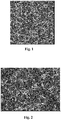
- a series of cylindrical platinum electrodes having a diameter of 2.2 mm and an active length of 0.75 mm was processed via ultrafast laser texturing. Each of the cylinders was rotated on its axis while the laser impinged the surface at a nearly oblique angle and the wavelength, number of pulses and laser irradiance were varied. Variations in operating parameters give the indicated potential polarization results.
- a Coherent Libra-F Ti:Sapphire amplifier laser system was used for the exposure.
- the laser exposure had a wavelength of 800 nm, an irradiance of 400 W/cm 2 and 100 pulses per spot.
- the resulting polarization was 600 mV.
- An example of a small surface feature size is approximately 4 nm and an example of a large surface feature size is approximately 107 nm.
- the laser exposure had a wavelength of 800 nm, an irradiance of 400 W/cm 2 and 10 pulses per spot.
- the resulting polarization was 829 mV.
- the surface topography is shown in Fig. 2 .
- the structure appears to be similar to that of Example 1, but the depth of the features is not as pronounced.
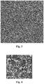
- the laser exposure had a wavelength of 800 nm, an irradiance of 100 W/cm 2 and 50 pulses per spot.
- the resulting polarization was 1100 mV, which is similar to that of an un-processed sample.
- Fig. 3 shows the desired inventive structure does not appear to be present.
- the laser exposure had a wavelength of 400 nm, an irradiance of 1000 W/cm 2 and 100 pulses per spot.
- the resulting polarization was 700 mV.
- Fig. 4 shows the structure appears to be similar to Fig. 1 but with less definition in the features.
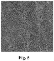
- the laser exposure had a wavelength of 400nm, an irradiance of 64 W/cm 2 and 10 pulses per spot.
- the resulting polarization was 996 mV.
- the surface does not present any features of the invention. The only features present are due to the process used to form the material into bar stock.
Landscapes
- Health & Medical Sciences (AREA)
- Life Sciences & Earth Sciences (AREA)
- Engineering & Computer Science (AREA)
- Physics & Mathematics (AREA)
- Public Health (AREA)
- Animal Behavior & Ethology (AREA)
- Biomedical Technology (AREA)
- Heart & Thoracic Surgery (AREA)
- Veterinary Medicine (AREA)
- General Health & Medical Sciences (AREA)
- Optics & Photonics (AREA)
- Cardiology (AREA)
- Surgery (AREA)
- Molecular Biology (AREA)
- Medical Informatics (AREA)
- Biophysics (AREA)
- Pathology (AREA)
- Chemical & Material Sciences (AREA)
- Plasma & Fusion (AREA)
- Mechanical Engineering (AREA)
- Nuclear Medicine, Radiotherapy & Molecular Imaging (AREA)
- Radiology & Medical Imaging (AREA)
- Chemical Kinetics & Catalysis (AREA)
- Electrochemistry (AREA)
- Materials Engineering (AREA)
- Metallurgy (AREA)
- Organic Chemistry (AREA)
- Electrotherapy Devices (AREA)
- Measuring And Recording Apparatus For Diagnosis (AREA)
- Measurement And Recording Of Electrical Phenomena And Electrical Characteristics Of The Living Body (AREA)
Claims (15)
- Elektrode, wobei die Elektrode umfasst: ein massives, monolithisches Substrat mit einer Außenumfangsfläche, wobei die Außenumfangsfläche eine Topographie aufweist, die durch eine Vielzahl von Leerstellen definiert ist, die über die Außenumfangsfläche verteilt sind und sich in eine Eindringtiefe in das Substrat hinein erstrecken, dadurch gekennzeichnet, dass diese Leerstellen eine Tiefe in das Substrat hinein von 50 nm bis 500 nm und diese Leerstellen eine Breite von 50 nm bis 500 nm haben, und diese Leerstellen von benachbarten Leerstellen einen Abstand von 50 nm bis 250 nm haben.
- Elektrode nach Anspruch 1, wobei die Leerstellen eine Eindringtiefe in das Substrat von 100 nm bis 250 nm haben; und diese Leerstellen eine Breite von 100 nm bis 250 nm haben.
- Elektrode nach einem der vorhergehenden Ansprüche, die eine Beschaffenheit hat, die geeignet ist, in das Gewebe eines Säugetiers implantiert zu werden.
- Elektrode nach einem der vorhergehenden Ansprüche, wobei das Substrat ein biokompatibles Metall umfasst, das aus einer Gruppe, die aus Platin, Stahl, Legierungen aus Platin und Iridium, und Legierungen aus Nickel und Kobalt besteht, ausgewählt wird.
- Elektrode nach einem der vorhergehenden Ansprüche, mit einer Außenumfangsfläche von 1 mm2 bis 20 mm2.
- Elektrode nach einem der vorhergehenden Ansprüche, ferner umfassend wenigstens einen elektrischen Verbinder, der an einem seiner Enden elektrisch mit dem Substrat verbunden ist.
- Elektrode nach Anspruch 6, die einen elektrischen Impulsgenerator umfasst, der mit einem anderen Ende des elektrischen Verbinders verbunden ist.
- Elektrode nach einem der Ansprüche 6 und 7, ferner umfassend eine elektrische Messvorrichtung, die mit einem anderen Ende des elektrischen Verbinders verbunden ist.
- Verfahren zum Herstellen einer Elektrode nach einem der Ansprüche 1 bis 8, mit einem massiven, monolithischen Substrat mit einer Außenumfangsfläche; wobei die Außenumfangsfläche eine Topographie hat, die durch eine Vielzahl von Leerstellen definiert ist, die über die Außenumfangsfläche verteilt sind und sich in eine Eindringtiefe in das Substrat hinein erstrecken, wobei das Verfahren den Schritt umfasst, ein massives, monolithisches Substrat einer Laserbestrahlung von 10 bis 500 Impulsen mit einer Wellenlänge von 200 nm bis 1600 nm bei einer Impulsdauer von 1 Femtosekunde bis 5 Pikosekunden und bei einer Bestrahlungsstärke von 200 Watt/cm2 bis 5000 Watt/cm2 auszusetzen.
- Verfahren nach Anspruch 9, wobei die Laserbestrahlung auf der Außenumfangsfläche einen Punktdurchmesser von 10 µm bis 10,000 µm hat.
- Verfahren nach einem der Ansprüche 9 und 10, wobei diese Leerstellen eine Eindringtiefe in das Substrat hinein von 50 nm bis 500 nm, vorzugsweise von 100 nm bis 250 nm haben; und diese Leerstellen eine Breite von 50 nm bis 500 nm, bevorzugt von 100 nm bis 250 nm haben; wobei jeder Leerstelle von benachbarten Leerstellen einen Abstand von 50 nm bis 250 nm hat.
- Verfahren nach einem der Ansprüche 9 bis 11, wobei das Substrat ein biokompatibles Metall umfasst, das aus einer Gruppe die aus Platin, Stahl, Legierungen aus Platin und Iridium, und Legierungen aus Nickel und Kobalt besteht, ausgewählt wird.
- Verfahren nach einem der Ansprüche 9 bis 12, ferner umfassend den Schritt wenigstens einen elektrischen Verbinder mit einem seiner Enden elektrisch mit dem Substrat zu verbinden, vorzugweise ferner einen elektrischen Impulsgenerator elektrisch mit einem anderen Ende des elektrischen Verbinders zu verbinden, und insbesondere ferner eine elektrische Messvorrichtung elektrisch mit einem anderen Ende des elektrischen Verbinders zu verbinden.
- Elektrischer Impulsgenerator, versehen mit einer Elektrode nach einem der Ansprüche 1 bis 8.
- Elektrische Messvorrichtung, versehen mit einer Elektrode nach einem der Ansprüche 1 bis 8.
Priority Applications (1)
| Application Number | Priority Date | Filing Date | Title |
|---|---|---|---|
| PL14168637T PL2808053T3 (pl) | 2013-05-30 | 2014-05-16 | Biokompatybilna elektroda wszczepialna |
Applications Claiming Priority (1)
| Application Number | Priority Date | Filing Date | Title |
|---|---|---|---|
| US13/905,851 US10791945B2 (en) | 2013-05-30 | 2013-05-30 | Biocompatible implantable electrode |
Publications (2)
| Publication Number | Publication Date |
|---|---|
| EP2808053A1 EP2808053A1 (de) | 2014-12-03 |
| EP2808053B1 true EP2808053B1 (de) | 2019-03-13 |
Family
ID=50729389
Family Applications (1)
| Application Number | Title | Priority Date | Filing Date |
|---|---|---|---|
| EP14168637.8A Active EP2808053B1 (de) | 2013-05-30 | 2014-05-16 | Biologisch verträgliche implantierbare Elektrode |
Country Status (7)
| Country | Link |
|---|---|
| US (2) | US10791945B2 (de) |
| EP (1) | EP2808053B1 (de) |
| JP (2) | JP6941414B2 (de) |
| AU (1) | AU2014202893B2 (de) |
| CA (1) | CA2850878C (de) |
| IL (1) | IL232460B (de) |
| PL (1) | PL2808053T3 (de) |
Families Citing this family (8)
| Publication number | Priority date | Publication date | Assignee | Title |
|---|---|---|---|---|
| US10791945B2 (en) | 2013-05-30 | 2020-10-06 | Pulse Ip, Llc | Biocompatible implantable electrode |
| US10827936B2 (en) * | 2013-08-15 | 2020-11-10 | Advanced Bionics Ag | Surface modified electrodes |
| US9117680B2 (en) * | 2013-12-20 | 2015-08-25 | Pulse Technologies Inc. | Biomedical electrode |
| US10219715B2 (en) * | 2015-06-17 | 2019-03-05 | Pulse Technologies, Inc. | Biomedical electrode having low oxygen content |
| US20200194771A1 (en) * | 2018-12-12 | 2020-06-18 | NeuroTronik IP Holding (Jersey) Limited | Medical electrodes having enhanced charge capacities, and methods of manufacturing |
| CN112187223B (zh) * | 2020-09-23 | 2023-07-07 | 西安交通大学 | 一种基于微带电路的宽频带脉冲电场辐照装置 |
| WO2022167956A1 (en) * | 2021-02-08 | 2022-08-11 | Cochlear Limited | Medical implant electrodes with controlled porosity |
| US11495369B2 (en) | 2021-03-25 | 2022-11-08 | Heraeus Deutschland GmbH & Co. KG | Laser structured, coated electrical conductor and method for producing same |
Family Cites Families (15)
| Publication number | Priority date | Publication date | Assignee | Title |
|---|---|---|---|---|
| DE4207368A1 (de) | 1991-08-06 | 1993-02-11 | Biotronik Mess & Therapieg | Stimmulationselektrode |
| US5318572A (en) | 1992-06-02 | 1994-06-07 | Siemens Pacesetter, Inc. | High efficiency tissue stimulating and signal sensing electrode |
| US6799076B2 (en) | 1999-12-07 | 2004-09-28 | Greatbatch-Hittman, Inc. | Coated electrode and method of making a coated electrode |
| JP4644797B2 (ja) * | 2004-01-28 | 2011-03-02 | 国立大学法人京都大学 | レーザ照射方法及び装置、微細加工方法及び装置、並びに薄膜形成方法及び装置 |
| US20060108327A1 (en) * | 2004-11-23 | 2006-05-25 | Chng Kiong C | Method of manufacturing a microstructure |
| WO2007095549A2 (en) | 2006-02-13 | 2007-08-23 | Medtronic, Inc. | Medical devices having textured surfaces |
| AU2007258562B2 (en) | 2006-06-06 | 2012-02-23 | Doheny Eye Institute | Molded polymer comprising silicone and at least one metal trace and a process of manufacturing the same |
| US8996129B2 (en) | 2007-01-31 | 2015-03-31 | Medtronic, Inc. | Medical electrode including an iridium oxide surface and methods of fabrication |
| US20080299289A1 (en) | 2007-05-29 | 2008-12-04 | Fisk Andrew E | Optimum Surface Texture Geometry |
| US8782884B2 (en) | 2009-12-01 | 2014-07-22 | Cochlear Limited | Manufacturing an electrode assembly having contoured electrode contact surfaces |
| US8463398B2 (en) | 2009-12-30 | 2013-06-11 | Cardiac Pacemakers, Inc. | Electrode surface modification for imparting current density directionality in lead electrodes |
| US8728563B2 (en) * | 2011-05-03 | 2014-05-20 | Palmaz Scientific, Inc. | Endoluminal implantable surfaces, stents, and grafts and method of making same |
| JP2013074956A (ja) * | 2011-09-30 | 2013-04-25 | Nidek Co Ltd | 生体組織用刺激電極及び該刺激電極の加工方法 |
| US20130296678A1 (en) * | 2012-04-24 | 2013-11-07 | Cardiac Pacemakers, Inc. | Combination structural porous surfaces for functional electrode stimulation and sensing |
| US10791945B2 (en) | 2013-05-30 | 2020-10-06 | Pulse Ip, Llc | Biocompatible implantable electrode |
-
2013
- 2013-05-30 US US13/905,851 patent/US10791945B2/en active Active
-
2014
- 2014-04-29 CA CA2850878A patent/CA2850878C/en active Active
- 2014-05-05 IL IL232460A patent/IL232460B/en unknown
- 2014-05-16 PL PL14168637T patent/PL2808053T3/pl unknown
- 2014-05-16 EP EP14168637.8A patent/EP2808053B1/de active Active
- 2014-05-27 JP JP2014109475A patent/JP6941414B2/ja active Active
- 2014-05-28 AU AU2014202893A patent/AU2014202893B2/en active Active
-
2019
- 2019-05-20 JP JP2019094362A patent/JP2019136556A/ja active Pending
-
2020
- 2020-10-06 US US17/064,513 patent/US20240215885A1/en not_active Abandoned
Non-Patent Citations (1)
| Title |
|---|
| None * |
Also Published As
| Publication number | Publication date |
|---|---|
| US20240215885A1 (en) | 2024-07-04 |
| IL232460A0 (en) | 2014-08-31 |
| PL2808053T3 (pl) | 2019-11-29 |
| US10791945B2 (en) | 2020-10-06 |
| CA2850878A1 (en) | 2014-11-30 |
| AU2014202893B2 (en) | 2019-03-21 |
| IL232460B (en) | 2021-07-29 |
| JP6941414B2 (ja) | 2021-09-29 |
| US20140357973A1 (en) | 2014-12-04 |
| EP2808053A1 (de) | 2014-12-03 |
| JP2019136556A (ja) | 2019-08-22 |
| CA2850878C (en) | 2022-10-04 |
| AU2014202893A1 (en) | 2014-12-18 |
| JP2014233630A (ja) | 2014-12-15 |
Similar Documents
| Publication | Publication Date | Title |
|---|---|---|
| US20240215885A1 (en) | Biocompatible implantable electrode | |
| AU2020202344B2 (en) | Biomedical electrode | |
| AU2021201430B2 (en) | Biomedical electrode having low oxygen content | |
| EP2736402B1 (de) | Optoelektrische vorrichtung und artefaktreduzierungsverfahren dafür | |
| US20210285085A1 (en) | Optimum Surface Texture Geometry | |
| Kim et al. | Iridium oxide–electrodeposited nanoporous gold multielectrode array with enhanced stimulus efficacy | |
| US20140326482A1 (en) | Iridium Oxide Coating with Cauliflower Morphology for Functional Electrical Stimulation Applications | |
| Negi et al. | INCREASE IN LONGIVITY OF IMPLANTABLE NEURAL DEVICE USING NOVEL MATERIAL | |
| CN114602059B (zh) | 电极触点的加工方法及植入式电极 | |
| US12403300B2 (en) | Electrode for a medical device | |
| Amini et al. | Advances in Manufacturing Next Generation Neurostimulation, Cardiac Rhythm Management, and Ultra-High-Density Electrophysiology Mapping Catheter Electrodes via Femtosecond Laser Hierarchical Surface Restructuring | |
| WO2019090396A1 (en) | A method of fabricating an electrode structure |
Legal Events
| Date | Code | Title | Description |
|---|---|---|---|
| PUAI | Public reference made under article 153(3) epc to a published international application that has entered the european phase |
Free format text: ORIGINAL CODE: 0009012 |
|
| 17P | Request for examination filed |
Effective date: 20140516 |
|
| AK | Designated contracting states |
Kind code of ref document: A1 Designated state(s): AL AT BE BG CH CY CZ DE DK EE ES FI FR GB GR HR HU IE IS IT LI LT LU LV MC MK MT NL NO PL PT RO RS SE SI SK SM TR |
|
| AX | Request for extension of the european patent |
Extension state: BA ME |
|
| R17P | Request for examination filed (corrected) |
Effective date: 20150603 |
|
| RBV | Designated contracting states (corrected) |
Designated state(s): AL AT BE BG CH CY CZ DE DK EE ES FI FR GB GR HR HU IE IS IT LI LT LU LV MC MK MT NL NO PL PT RO RS SE SI SK SM TR |
|
| STAA | Information on the status of an ep patent application or granted ep patent |
Free format text: STATUS: EXAMINATION IS IN PROGRESS |
|
| 17Q | First examination report despatched |
Effective date: 20170320 |
|
| GRAP | Despatch of communication of intention to grant a patent |
Free format text: ORIGINAL CODE: EPIDOSNIGR1 |
|
| STAA | Information on the status of an ep patent application or granted ep patent |
Free format text: STATUS: GRANT OF PATENT IS INTENDED |
|
| INTG | Intention to grant announced |
Effective date: 20181002 |
|
| RAP1 | Party data changed (applicant data changed or rights of an application transferred) |
Owner name: PULSE IP, LLC |
|
| GRAS | Grant fee paid |
Free format text: ORIGINAL CODE: EPIDOSNIGR3 |
|
| GRAA | (expected) grant |
Free format text: ORIGINAL CODE: 0009210 |
|
| STAA | Information on the status of an ep patent application or granted ep patent |
Free format text: STATUS: THE PATENT HAS BEEN GRANTED |
|
| AK | Designated contracting states |
Kind code of ref document: B1 Designated state(s): AL AT BE BG CH CY CZ DE DK EE ES FI FR GB GR HR HU IE IS IT LI LT LU LV MC MK MT NL NO PL PT RO RS SE SI SK SM TR |
|
| REG | Reference to a national code |
Ref country code: GB Ref legal event code: FG4D |
|
| REG | Reference to a national code |
Ref country code: CH Ref legal event code: EP Ref country code: AT Ref legal event code: REF Ref document number: 1106875 Country of ref document: AT Kind code of ref document: T Effective date: 20190315 |
|
| REG | Reference to a national code |
Ref country code: IE Ref legal event code: FG4D |
|
| REG | Reference to a national code |
Ref country code: DE Ref legal event code: R096 Ref document number: 602014042681 Country of ref document: DE |
|
| REG | Reference to a national code |
Ref country code: SE Ref legal event code: TRGR |
|
| REG | Reference to a national code |
Ref country code: NL Ref legal event code: FP |
|
| REG | Reference to a national code |
Ref country code: LT Ref legal event code: MG4D |
|
| PG25 | Lapsed in a contracting state [announced via postgrant information from national office to epo] |
Ref country code: FI Free format text: LAPSE BECAUSE OF FAILURE TO SUBMIT A TRANSLATION OF THE DESCRIPTION OR TO PAY THE FEE WITHIN THE PRESCRIBED TIME-LIMIT Effective date: 20190313 Ref country code: NO Free format text: LAPSE BECAUSE OF FAILURE TO SUBMIT A TRANSLATION OF THE DESCRIPTION OR TO PAY THE FEE WITHIN THE PRESCRIBED TIME-LIMIT Effective date: 20190613 Ref country code: LT Free format text: LAPSE BECAUSE OF FAILURE TO SUBMIT A TRANSLATION OF THE DESCRIPTION OR TO PAY THE FEE WITHIN THE PRESCRIBED TIME-LIMIT Effective date: 20190313 |
|
| REG | Reference to a national code |
Ref country code: CH Ref legal event code: NV Representative=s name: RIEDERER HASLER AND PARTNER PATENTANWAELTE AG, CH |
|
| PG25 | Lapsed in a contracting state [announced via postgrant information from national office to epo] |
Ref country code: GR Free format text: LAPSE BECAUSE OF FAILURE TO SUBMIT A TRANSLATION OF THE DESCRIPTION OR TO PAY THE FEE WITHIN THE PRESCRIBED TIME-LIMIT Effective date: 20190614 Ref country code: HR Free format text: LAPSE BECAUSE OF FAILURE TO SUBMIT A TRANSLATION OF THE DESCRIPTION OR TO PAY THE FEE WITHIN THE PRESCRIBED TIME-LIMIT Effective date: 20190313 Ref country code: LV Free format text: LAPSE BECAUSE OF FAILURE TO SUBMIT A TRANSLATION OF THE DESCRIPTION OR TO PAY THE FEE WITHIN THE PRESCRIBED TIME-LIMIT Effective date: 20190313 Ref country code: BG Free format text: LAPSE BECAUSE OF FAILURE TO SUBMIT A TRANSLATION OF THE DESCRIPTION OR TO PAY THE FEE WITHIN THE PRESCRIBED TIME-LIMIT Effective date: 20190613 Ref country code: RS Free format text: LAPSE BECAUSE OF FAILURE TO SUBMIT A TRANSLATION OF THE DESCRIPTION OR TO PAY THE FEE WITHIN THE PRESCRIBED TIME-LIMIT Effective date: 20190313 |
|
| PG25 | Lapsed in a contracting state [announced via postgrant information from national office to epo] |
Ref country code: RO Free format text: LAPSE BECAUSE OF FAILURE TO SUBMIT A TRANSLATION OF THE DESCRIPTION OR TO PAY THE FEE WITHIN THE PRESCRIBED TIME-LIMIT Effective date: 20190313 Ref country code: EE Free format text: LAPSE BECAUSE OF FAILURE TO SUBMIT A TRANSLATION OF THE DESCRIPTION OR TO PAY THE FEE WITHIN THE PRESCRIBED TIME-LIMIT Effective date: 20190313 Ref country code: ES Free format text: LAPSE BECAUSE OF FAILURE TO SUBMIT A TRANSLATION OF THE DESCRIPTION OR TO PAY THE FEE WITHIN THE PRESCRIBED TIME-LIMIT Effective date: 20190313 Ref country code: PT Free format text: LAPSE BECAUSE OF FAILURE TO SUBMIT A TRANSLATION OF THE DESCRIPTION OR TO PAY THE FEE WITHIN THE PRESCRIBED TIME-LIMIT Effective date: 20190713 Ref country code: AL Free format text: LAPSE BECAUSE OF FAILURE TO SUBMIT A TRANSLATION OF THE DESCRIPTION OR TO PAY THE FEE WITHIN THE PRESCRIBED TIME-LIMIT Effective date: 20190313 Ref country code: SK Free format text: LAPSE BECAUSE OF FAILURE TO SUBMIT A TRANSLATION OF THE DESCRIPTION OR TO PAY THE FEE WITHIN THE PRESCRIBED TIME-LIMIT Effective date: 20190313 |
|
| PG25 | Lapsed in a contracting state [announced via postgrant information from national office to epo] |
Ref country code: SM Free format text: LAPSE BECAUSE OF FAILURE TO SUBMIT A TRANSLATION OF THE DESCRIPTION OR TO PAY THE FEE WITHIN THE PRESCRIBED TIME-LIMIT Effective date: 20190313 |
|
| REG | Reference to a national code |
Ref country code: DE Ref legal event code: R097 Ref document number: 602014042681 Country of ref document: DE |
|
| PG25 | Lapsed in a contracting state [announced via postgrant information from national office to epo] |
Ref country code: IS Free format text: LAPSE BECAUSE OF FAILURE TO SUBMIT A TRANSLATION OF THE DESCRIPTION OR TO PAY THE FEE WITHIN THE PRESCRIBED TIME-LIMIT Effective date: 20190713 |
|
| PLBE | No opposition filed within time limit |
Free format text: ORIGINAL CODE: 0009261 |
|
| STAA | Information on the status of an ep patent application or granted ep patent |
Free format text: STATUS: NO OPPOSITION FILED WITHIN TIME LIMIT |
|
| PG25 | Lapsed in a contracting state [announced via postgrant information from national office to epo] |
Ref country code: DK Free format text: LAPSE BECAUSE OF FAILURE TO SUBMIT A TRANSLATION OF THE DESCRIPTION OR TO PAY THE FEE WITHIN THE PRESCRIBED TIME-LIMIT Effective date: 20190313 Ref country code: MC Free format text: LAPSE BECAUSE OF FAILURE TO SUBMIT A TRANSLATION OF THE DESCRIPTION OR TO PAY THE FEE WITHIN THE PRESCRIBED TIME-LIMIT Effective date: 20190313 |
|
| REG | Reference to a national code |
Ref country code: BE Ref legal event code: MM Effective date: 20190531 |
|
| 26N | No opposition filed |
Effective date: 20191216 |
|
| PG25 | Lapsed in a contracting state [announced via postgrant information from national office to epo] |
Ref country code: SI Free format text: LAPSE BECAUSE OF FAILURE TO SUBMIT A TRANSLATION OF THE DESCRIPTION OR TO PAY THE FEE WITHIN THE PRESCRIBED TIME-LIMIT Effective date: 20190313 Ref country code: LU Free format text: LAPSE BECAUSE OF NON-PAYMENT OF DUE FEES Effective date: 20190516 |
|
| PG25 | Lapsed in a contracting state [announced via postgrant information from national office to epo] |
Ref country code: TR Free format text: LAPSE BECAUSE OF FAILURE TO SUBMIT A TRANSLATION OF THE DESCRIPTION OR TO PAY THE FEE WITHIN THE PRESCRIBED TIME-LIMIT Effective date: 20190313 |
|
| PG25 | Lapsed in a contracting state [announced via postgrant information from national office to epo] |
Ref country code: BE Free format text: LAPSE BECAUSE OF NON-PAYMENT OF DUE FEES Effective date: 20190531 |
|
| PG25 | Lapsed in a contracting state [announced via postgrant information from national office to epo] |
Ref country code: CY Free format text: LAPSE BECAUSE OF FAILURE TO SUBMIT A TRANSLATION OF THE DESCRIPTION OR TO PAY THE FEE WITHIN THE PRESCRIBED TIME-LIMIT Effective date: 20190313 |
|
| PG25 | Lapsed in a contracting state [announced via postgrant information from national office to epo] |
Ref country code: MT Free format text: LAPSE BECAUSE OF FAILURE TO SUBMIT A TRANSLATION OF THE DESCRIPTION OR TO PAY THE FEE WITHIN THE PRESCRIBED TIME-LIMIT Effective date: 20190313 Ref country code: HU Free format text: LAPSE BECAUSE OF FAILURE TO SUBMIT A TRANSLATION OF THE DESCRIPTION OR TO PAY THE FEE WITHIN THE PRESCRIBED TIME-LIMIT; INVALID AB INITIO Effective date: 20140516 |
|
| PG25 | Lapsed in a contracting state [announced via postgrant information from national office to epo] |
Ref country code: MK Free format text: LAPSE BECAUSE OF FAILURE TO SUBMIT A TRANSLATION OF THE DESCRIPTION OR TO PAY THE FEE WITHIN THE PRESCRIBED TIME-LIMIT Effective date: 20190313 |
|
| REG | Reference to a national code |
Ref country code: AT Ref legal event code: UEP Ref document number: 1106875 Country of ref document: AT Kind code of ref document: T Effective date: 20190313 |
|
| PGFP | Annual fee paid to national office [announced via postgrant information from national office to epo] |
Ref country code: PL Payment date: 20250307 Year of fee payment: 12 |
|
| PGFP | Annual fee paid to national office [announced via postgrant information from national office to epo] |
Ref country code: DE Payment date: 20250319 Year of fee payment: 12 |
|
| PGFP | Annual fee paid to national office [announced via postgrant information from national office to epo] |
Ref country code: IT Payment date: 20250422 Year of fee payment: 12 |
|
| PGFP | Annual fee paid to national office [announced via postgrant information from national office to epo] |
Ref country code: CH Payment date: 20250601 Year of fee payment: 12 |
|
| PGFP | Annual fee paid to national office [announced via postgrant information from national office to epo] |
Ref country code: AT Payment date: 20250425 Year of fee payment: 12 |
|
| PGFP | Annual fee paid to national office [announced via postgrant information from national office to epo] |
Ref country code: CZ Payment date: 20250430 Year of fee payment: 12 |
|
| PGFP | Annual fee paid to national office [announced via postgrant information from national office to epo] |
Ref country code: SE Payment date: 20260312 Year of fee payment: 13 |
|
| PGFP | Annual fee paid to national office [announced via postgrant information from national office to epo] |
Ref country code: GB Payment date: 20260312 Year of fee payment: 13 |
|
| PGFP | Annual fee paid to national office [announced via postgrant information from national office to epo] |
Ref country code: IE Payment date: 20260310 Year of fee payment: 13 |
|
| PGFP | Annual fee paid to national office [announced via postgrant information from national office to epo] |
Ref country code: NL Payment date: 20260317 Year of fee payment: 13 |
|
| PGFP | Annual fee paid to national office [announced via postgrant information from national office to epo] |
Ref country code: FR Payment date: 20260309 Year of fee payment: 13 |