EP2807973A1 - Endoscope system, processor device for endoscope system, and image processing method - Google Patents
Endoscope system, processor device for endoscope system, and image processing method Download PDFInfo
- Publication number
- EP2807973A1 EP2807973A1 EP13741638.4A EP13741638A EP2807973A1 EP 2807973 A1 EP2807973 A1 EP 2807973A1 EP 13741638 A EP13741638 A EP 13741638A EP 2807973 A1 EP2807973 A1 EP 2807973A1
- Authority
- EP
- European Patent Office
- Prior art keywords
- blood vessel
- light
- image
- illumination light
- amount ratio
- Prior art date
- Legal status (The legal status is an assumption and is not a legal conclusion. Google has not performed a legal analysis and makes no representation as to the accuracy of the status listed.)
- Granted
Links
Images











Classifications
-
- A—HUMAN NECESSITIES
- A61—MEDICAL OR VETERINARY SCIENCE; HYGIENE
- A61B—DIAGNOSIS; SURGERY; IDENTIFICATION
- A61B1/00—Instruments for performing medical examinations of the interior of cavities or tubes of the body by visual or photographical inspection, e.g. endoscopes; Illuminating arrangements therefor
- A61B1/00002—Operational features of endoscopes
- A61B1/00004—Operational features of endoscopes characterised by electronic signal processing
- A61B1/00009—Operational features of endoscopes characterised by electronic signal processing of image signals during a use of endoscope
- A61B1/000094—Operational features of endoscopes characterised by electronic signal processing of image signals during a use of endoscope extracting biological structures
-
- A—HUMAN NECESSITIES
- A61—MEDICAL OR VETERINARY SCIENCE; HYGIENE
- A61B—DIAGNOSIS; SURGERY; IDENTIFICATION
- A61B1/00—Instruments for performing medical examinations of the interior of cavities or tubes of the body by visual or photographical inspection, e.g. endoscopes; Illuminating arrangements therefor
- A61B1/04—Instruments for performing medical examinations of the interior of cavities or tubes of the body by visual or photographical inspection, e.g. endoscopes; Illuminating arrangements therefor combined with photographic or television appliances
- A61B1/043—Instruments for performing medical examinations of the interior of cavities or tubes of the body by visual or photographical inspection, e.g. endoscopes; Illuminating arrangements therefor combined with photographic or television appliances for fluorescence imaging
-
- A—HUMAN NECESSITIES
- A61—MEDICAL OR VETERINARY SCIENCE; HYGIENE
- A61B—DIAGNOSIS; SURGERY; IDENTIFICATION
- A61B1/00—Instruments for performing medical examinations of the interior of cavities or tubes of the body by visual or photographical inspection, e.g. endoscopes; Illuminating arrangements therefor
- A61B1/06—Instruments for performing medical examinations of the interior of cavities or tubes of the body by visual or photographical inspection, e.g. endoscopes; Illuminating arrangements therefor with illuminating arrangements
- A61B1/0638—Instruments for performing medical examinations of the interior of cavities or tubes of the body by visual or photographical inspection, e.g. endoscopes; Illuminating arrangements therefor with illuminating arrangements providing two or more wavelengths
-
- A—HUMAN NECESSITIES
- A61—MEDICAL OR VETERINARY SCIENCE; HYGIENE
- A61B—DIAGNOSIS; SURGERY; IDENTIFICATION
- A61B1/00—Instruments for performing medical examinations of the interior of cavities or tubes of the body by visual or photographical inspection, e.g. endoscopes; Illuminating arrangements therefor
- A61B1/06—Instruments for performing medical examinations of the interior of cavities or tubes of the body by visual or photographical inspection, e.g. endoscopes; Illuminating arrangements therefor with illuminating arrangements
- A61B1/0646—Instruments for performing medical examinations of the interior of cavities or tubes of the body by visual or photographical inspection, e.g. endoscopes; Illuminating arrangements therefor with illuminating arrangements with illumination filters
-
- A—HUMAN NECESSITIES
- A61—MEDICAL OR VETERINARY SCIENCE; HYGIENE
- A61B—DIAGNOSIS; SURGERY; IDENTIFICATION
- A61B1/00—Instruments for performing medical examinations of the interior of cavities or tubes of the body by visual or photographical inspection, e.g. endoscopes; Illuminating arrangements therefor
- A61B1/06—Instruments for performing medical examinations of the interior of cavities or tubes of the body by visual or photographical inspection, e.g. endoscopes; Illuminating arrangements therefor with illuminating arrangements
- A61B1/0653—Instruments for performing medical examinations of the interior of cavities or tubes of the body by visual or photographical inspection, e.g. endoscopes; Illuminating arrangements therefor with illuminating arrangements with wavelength conversion
-
- A—HUMAN NECESSITIES
- A61—MEDICAL OR VETERINARY SCIENCE; HYGIENE
- A61B—DIAGNOSIS; SURGERY; IDENTIFICATION
- A61B5/00—Measuring for diagnostic purposes; Identification of persons
- A61B5/0059—Measuring for diagnostic purposes; Identification of persons using light, e.g. diagnosis by transillumination, diascopy, fluorescence
- A61B5/0082—Measuring for diagnostic purposes; Identification of persons using light, e.g. diagnosis by transillumination, diascopy, fluorescence adapted for particular medical purposes
- A61B5/0084—Measuring for diagnostic purposes; Identification of persons using light, e.g. diagnosis by transillumination, diascopy, fluorescence adapted for particular medical purposes for introduction into the body, e.g. by catheters
-
- A—HUMAN NECESSITIES
- A61—MEDICAL OR VETERINARY SCIENCE; HYGIENE
- A61B—DIAGNOSIS; SURGERY; IDENTIFICATION
- A61B5/00—Measuring for diagnostic purposes; Identification of persons
- A61B5/02—Detecting, measuring or recording for evaluating the cardiovascular system, e.g. pulse, heart rate, blood pressure or blood flow
- A61B5/02007—Evaluating blood vessel condition, e.g. elasticity, compliance
-
- G—PHYSICS
- G06—COMPUTING OR CALCULATING; COUNTING
- G06T—IMAGE DATA PROCESSING OR GENERATION, IN GENERAL
- G06T11/00—Two-dimensional [2D] image generation
- G06T11/10—Texturing; Colouring; Generation of textures or colours
-
- G—PHYSICS
- G06—COMPUTING OR CALCULATING; COUNTING
- G06T—IMAGE DATA PROCESSING OR GENERATION, IN GENERAL
- G06T7/00—Image analysis
- G06T7/0002—Inspection of images, e.g. flaw detection
- G06T7/0012—Biomedical image inspection
-
- G—PHYSICS
- G06—COMPUTING OR CALCULATING; COUNTING
- G06T—IMAGE DATA PROCESSING OR GENERATION, IN GENERAL
- G06T7/00—Image analysis
- G06T7/90—Determination of colour characteristics
-
- G—PHYSICS
- G06—COMPUTING OR CALCULATING; COUNTING
- G06V—IMAGE OR VIDEO RECOGNITION OR UNDERSTANDING
- G06V20/00—Scenes; Scene-specific elements
- G06V20/60—Type of objects
- G06V20/69—Microscopic objects, e.g. biological cells or cellular parts
- G06V20/695—Preprocessing, e.g. image segmentation
-
- A—HUMAN NECESSITIES
- A61—MEDICAL OR VETERINARY SCIENCE; HYGIENE
- A61B—DIAGNOSIS; SURGERY; IDENTIFICATION
- A61B1/00—Instruments for performing medical examinations of the interior of cavities or tubes of the body by visual or photographical inspection, e.g. endoscopes; Illuminating arrangements therefor
- A61B1/00002—Operational features of endoscopes
- A61B1/00043—Operational features of endoscopes provided with output arrangements
- A61B1/00045—Display arrangement
- A61B1/0005—Display arrangement combining images e.g. side-by-side, superimposed or tiled
-
- A—HUMAN NECESSITIES
- A61—MEDICAL OR VETERINARY SCIENCE; HYGIENE
- A61B—DIAGNOSIS; SURGERY; IDENTIFICATION
- A61B1/00—Instruments for performing medical examinations of the interior of cavities or tubes of the body by visual or photographical inspection, e.g. endoscopes; Illuminating arrangements therefor
- A61B1/06—Instruments for performing medical examinations of the interior of cavities or tubes of the body by visual or photographical inspection, e.g. endoscopes; Illuminating arrangements therefor with illuminating arrangements
- A61B1/063—Instruments for performing medical examinations of the interior of cavities or tubes of the body by visual or photographical inspection, e.g. endoscopes; Illuminating arrangements therefor with illuminating arrangements for monochromatic or narrow-band illumination
-
- G—PHYSICS
- G06—COMPUTING OR CALCULATING; COUNTING
- G06T—IMAGE DATA PROCESSING OR GENERATION, IN GENERAL
- G06T2207/00—Indexing scheme for image analysis or image enhancement
- G06T2207/10—Image acquisition modality
- G06T2207/10024—Color image
-
- G—PHYSICS
- G06—COMPUTING OR CALCULATING; COUNTING
- G06T—IMAGE DATA PROCESSING OR GENERATION, IN GENERAL
- G06T2207/00—Indexing scheme for image analysis or image enhancement
- G06T2207/10—Image acquisition modality
- G06T2207/10068—Endoscopic image
-
- G—PHYSICS
- G06—COMPUTING OR CALCULATING; COUNTING
- G06T—IMAGE DATA PROCESSING OR GENERATION, IN GENERAL
- G06T2207/00—Indexing scheme for image analysis or image enhancement
- G06T2207/10—Image acquisition modality
- G06T2207/10141—Special mode during image acquisition
- G06T2207/10152—Varying illumination
-
- G—PHYSICS
- G06—COMPUTING OR CALCULATING; COUNTING
- G06T—IMAGE DATA PROCESSING OR GENERATION, IN GENERAL
- G06T2207/00—Indexing scheme for image analysis or image enhancement
- G06T2207/30—Subject of image; Context of image processing
- G06T2207/30004—Biomedical image processing
- G06T2207/30101—Blood vessel; Artery; Vein; Vascular
Definitions
- the present invention relates to an endoscope system capable of extracting blood vessels, such as superficial blood vessels and medium-deep blood vessels, from a subject, a processor device of the endoscope system, and an image processing method.
- Types of blood vessels mainly include superficial blood vessels distributed on a living tissue surface and medium-deep blood vessels located below the superficial blood vessels.
- diagnosis may be performed focusing on certain blood vessels.
- diagnosis may be interrupted by the blood vessel. For this reason, differentiating superficial blood vessels or medium-deep blood vessels from the image and displaying an image, which is obtained by extracting only blood vessels to be observed, on a monitor has been demanded.
- JP2011-135983A discloses a method of performing determination as a superficial blood vessel when the hue of a narrowband image generated based on narrowband light in a specified wavelength region (415 nm, 540 nm) is 5 to 35 and performing determination as a medium-deep blood vessel when the hue is 170 to 200.
- a semiconductor light source such as a laser light source
- a semiconductor light source such as a laser light source
- a subject is illuminated with fluorescent light (green to red) that is excited and emitted by irradiating a phosphor with first blue laser light having a center wavelength of 405 nm and second blue laser light having a center wavelength of 445 nm.
- the ratio between the components of respective colors of illumination light is also changed by adjusting the light amount ratio between the first blue laser light and the second blue laser light. Since the degree of penetration of illumination light into the living tissue has a wavelength dependency, it is possible to change a part to be made clear.
- a superficial blood vessel can be made clear.
- a medium-deep blood vessel can be made clear.
- a blood vessel to be observed can be made clear by adjusting the light amount ratio.
- some blood vessels that are not to be observed are slightly displayed although not noticeable.
- the aforementioned slightly displayed blood vessels reduce the visibility of a blood vessel to be observed. Therefore, it is necessary to distinguish and extract only a blood vessel to be observed.
- the hue on the image is changed. For this reason, in the blood vessel discrimination method based on the hue disclosed in JP2011-135983A , it is not possible to reliably extract a blood vessel to be observed.
- the present invention has been made in view of the above-background, and it is an object of the present invention to provide an endoscope system capable of reliably extracting a plurality of types of blood vessels at different depths even if the ratio between blue and green components of illumination light irradiated to a subject is changed, a processor device of the endoscope system, and an image processing method.
- an endoscope system of the present invention includes: illumination means that includes a light emitting unit, which emits two or more illumination light beams including first illumination light and second illumination light having different wavelength regions, and a light amount ratio setting unit, which sets a light amount ratio between the first illumination light and the second illumination light, and that irradiates a subject with the first illumination light and the second illumination light based on the light amount ratio set by the light amount ratio setting unit; image signal acquisition means for acquiring two or more color signals having different pieces of color information by receiving and imaging return light from the subject using an imaging element; multi-color image generation means for generating a multi-color image formed from calculated values obtained by performing predetermined calculation for each pixel using the two or more color signals; and blood vessel extraction image generation means for generating at least one of a first layer blood vessel extraction image, which is obtained by extracting a first layer blood vessel at a specific depth from the multi-color image, and a second layer blood vessel extraction image, which is obtained by extracting a second layer
- the light amount ratio setting unit sets one of a plurality of light amount ratios set in advance
- the blood vessel extraction image generation means includes a plurality of calculated value tables, which are set for the plurality of light amount ratios and which store a correlation between a mucous membrane, the first layer blood vessel, and the second layer blood vessel of the subject and the calculated values, and a blood vessel extraction image generation unit that generates at least one of the first layer blood vessel extraction image and the second layer blood vessel extraction image by performing blood vessel extraction processing using a calculated value table corresponding to the light amount ratio set by the light amount ratio setting unit.
- a calculated value indicating a boundary between the mucous membrane and the first layer blood vessel is stored as a first boundary value
- a calculated value indicating a boundary between the mucous membrane and the second layer blood vessel is stored as a second boundary value.
- the first and second boundary values differ depending on each calculated value table.
- blood vessel enhancement image or suppression image generation means for generating a first layer blood vessel enhancement image or suppression image, in which the first layer blood vessel is enhanced or suppressed, using the first layer blood vessel extraction image or generating a second layer blood vessel enhancement image or suppression image, in which the second layer blood vessel is enhanced or suppressed, using the second layer blood vessel extraction image. It is preferable to further include display means for displaying at least one of the first layer blood vessel enhancement image or suppression image and the second layer blood vessel enhancement image or suppression image.
- the illumination means irradiates first illumination light, which includes blue excitation light and fluorescent light that is wavelength-converted by a wavelength conversion member using the blue excitation light, and second illumination light, which has a wavelength region in which a center wavelength is on a short wavelength side compared with the excitation light, simultaneously toward the subject.
- the image signal acquisition means images the subject, to which the first illumination light and the second illumination light are irradiated simultaneously, using a color imaging element.
- the wavelength conversion member is provided in a separate light source device from an endoscope that irradiates the first illumination light and the second illumination light toward the subject.
- the wavelength conversion member is provided at a distal end of an endoscope that irradiates the first illumination light and the second illumination light toward the subject.
- a center wavelength of the excitation light is 445 nm
- a center wavelength of the second illumination light is 405 nm.
- the first illumination light is illumination light having a center wavelength of 420 nm
- the second illumination light is illumination light having a center wavelength of 530 nm.
- the color signals include a blue signal having information of a blue component and a green signal having information of a green component
- the multi-color image is a B/G image having a B/G ratio obtained by dividing the blue signal by the green signal for each pixel.
- the center wavelength 420 nm of the first illumination light is intended to include a range in which a center wavelength is 420 nm ⁇ 5 nm
- the center wavelength 530 nm of the second illumination light is intended to include a range in which a center wavelength is 530 nm ⁇ 5 nm.
- a processor device of an endoscope system including illumination means, which includes a light emitting unit that emits two or more illumination light beams including first illumination light and second illumination light having different wavelength regions and a light amount ratio setting unit that sets a light amount ratio between the first illumination light and the second illumination light and which irradiates a subject with the first illumination light and the second illumination light based on the light amount ratio set by the light amount ratio setting unit, and an electronic endoscope for acquiring two or more color signals having different pieces of color information by receiving and imaging return light from the subject using an imaging element.
- the processor device of an endoscope system includes: multi-color image generation means for generating a multi-color image formed from calculated values obtained by performing predetermined calculation for each pixel using the two or more color signals; and blood vessel extraction image generation means for generating at least one of a first layer blood vessel extraction image, which is obtained by extracting a first layer blood vessel at a specific depth from the multi-color image, and a second layer blood vessel extraction image, which is obtained by extracting a second layer blood vessel at a position deeper than the first layer blood vessel from the multi-color image, by performing blood vessel extraction processing, which differs depending on the light amount ratio, on the multi-color image.
- an image processing method performed in an endoscope system including illumination means, which includes a light emitting unit that emits two or more illumination light beams including first illumination light and second illumination light having different wavelength regions and a light amount ratio setting unit that sets a light amount ratio between the first illumination light and the second illumination light and which irradiates a subject with the first illumination light and the second illumination light based on the light amount ratio set by the light amount ratio setting unit, and an electronic endoscope for acquiring two or more color signals having different pieces of color information by receiving and imaging return light from the subject using an imaging element.
- illumination means which includes a light emitting unit that emits two or more illumination light beams including first illumination light and second illumination light having different wavelength regions and a light amount ratio setting unit that sets a light amount ratio between the first illumination light and the second illumination light and which irradiates a subject with the first illumination light and the second illumination light based on the light amount ratio set by the light amount ratio setting unit, and an electronic endoscope for acquiring two or more color signals having different pieces of color
- the image processing method includes: generating a multi-color image formed from calculated values obtained by performing predetermined calculation for each pixel using the two or more color signals; and generating at least one of a first layer blood vessel extraction image, which is obtained by extracting a first layer blood vessel at a specific depth from the multi-color image, and a second layer blood vessel extraction image, which is obtained by extracting a second layer blood vessel at a position deeper than the first layer blood vessel from the multi-color image, by performing blood vessel extraction processing, which differs depending on the light amount ratio, on the multi-color image.
- the present invention since blood vessel extraction processing, which differs depending on the light amount ratio of the first illumination light and the second illumination light to illuminate a subject, is performed, it is possible to reliably extract a plurality of types of blood vessels at different depths even if the light amount ratio is changed.
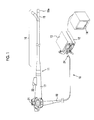
- an electronic endoscope system 10 includes an electronic endoscope 11 that images the inside of a subject, a processor device 12 that generates an endoscope image based on a signal obtained by imaging, a light source device 13 that generates light for illuminating the subject, and a monitor 14 that displays an endoscope image.
- the electronic endoscope 11 includes a flexible insertion unit 16 that is inserted into the body cavity, an operating unit 17 provided at the proximal end of the insertion unit 16, and a universal code 18 that makes a connection between the operating unit 17 and the processor device 12 and the light source device 13.
- the electronic endoscope system 10 has a function of generating a superficial blood vessel enhancement image or suppression image, in which a superficial blood vessel of a subject is enhanced/suppressed, and a medium-deep blood vessel enhancement image or suppression image, in which a medium-deep superficial blood vessel is enhanced/suppressed.
- Which blood vessel enhancement image or suppression image is to be generated is determined by the operation of a superficial layer and medium-deep layer selection SW 28 (refer to Fig. 2 ).
- the electronic endoscope system 10 has three observation modes of a first observation mode in which the inside of the subject is observed with illumination light in which the percentage of the blue component is approximately the same as the percentage of the green component, a second observation mode in which the inside of the subject is observed with illumination light in which the percentage of the blue component is larger than the percentage of the green component, and a third observation mode in which the inside of the subject is observed with illumination light in which the percentage of the green component is larger than the percentage of the blue component.
- the first to third observation modes are switched by an observation mode selection SW 29 (refer to Fig. 2 ).
- a curved portion 19 obtained by connecting a plurality of curved pieces is formed at the distal end of the insertion unit 16.
- the curved portion 19 is curved in the horizontal and vertical directions by operating an angle knob 21 of the operating unit.
- a distal portion 16a including an optical system for imaging the body cavity and the like is provided at the distal end of the curved portion 19. The distal portion 16a is directed in a desired direction within the body cavity by the bending operation of the curved portion 19.
- a connector 24 is attached to the universal code 18 on the side of the processor device 12 and the light source device 13.
- the connector 24 is a composite connector including a communication connector and a light source connector, and the electronic endoscope 11 is detachably connected to the processor device 12 and the light source device 13 through the connector 24.
- the light source device 13 (a form of illumination means) includes a broadband light source 30, a blue narrowband light source 33, a coupler 36, and a light source control unit 37.
- the broadband light source 30 includes an excitation light source 30a that emits excitation light having a center wavelength of 445 nm and a phosphor 30b that is excited to emit fluorescent light of green to red due to the excitation light from the excitation light source 30a.
- the excitation light source 30a is a semiconductor light source, such as a light emitting diode (LED) or a laser diode (LD).
- a broad area type InGaN-based laser diode can be used.
- an InGaNAs-based laser diode, a GaNAs-based laser diode, or the like can also be used.
- the phosphor 30b is configured to contain a plurality of kinds of fluorescent materials (for example, a YAG-based fluorescent material or a fluorescent material, such as BAM (BaMgAl 10 O 17 )) that absorb a part of excitation light and are excited to emit light of green to red. Accordingly, by combining the emitted excitation light (fluorescent light) of green to red emitted from the phosphor 30b with excitation light that is transmitted through the phosphor 30b without being absorbed by the phosphor 30b, white light BB (pseudo white light) having an emission spectrum shown in Fig. 3 is generated. The generated white light BB is incident on a broadband optical fiber 34.
- fluorescent materials for example, a YAG-based fluorescent material or a fluorescent material, such as BAM (BaMgAl 10 O 17 )
- the phosphor 30b may have an approximately rectangular parallelepiped shape.
- the phosphor 30b may be formed by solidifying a phosphor material in an approximately rectangular parallelepiped shape using a binder, or may be formed in an approximately rectangular parallelepiped shape by mixing a phosphor material with resin, such as inorganic glass.
- the phosphor 30b is also referred to as a Micro White (MW, registered trademark) as a product name.
- the blue narrowband light source 33 is a light emitting diode (LED), a laser diode (LD), or the like. As shown in Fig. 3 , the blue narrowband light source 33 generates blue narrowband light BN having a limited wavelength of 400 ⁇ 10 nm (center wavelength of 405 nm). The blue narrowband light BN emitted from the blue narrowband light source 33 is incident on a narrowband optical fiber 35.
- LED light emitting diode
- LD laser diode
- the coupler 36 connects a light guide 43 in the electronic endoscope 11 to the broadband optical fiber 34 and the narrowband optical fiber 35. Therefore, both the white light BB and the blue narrowband light BN are simultaneously incident on the light guide 43.
- the light source control unit 37 controls the light amount of the excitation light source 30a and the blue narrowband light source 33 to maintain the light amount ratio of the white light BB and the blue narrowband light BN constant.
- the light amount ratio is set by a light amount ratio setting section 37a. Since the light amount ratio is set in advance for each of the first to third observation modes, the light amount ratio setting section 37a sets a light amount ratio corresponding to the observation mode selected by the observation mode selection SW 29.
- the first light amount ratio in the first observation mode is set such that the percentage of the blue component of the illumination light irradiated to the subject is approximately the same as the percentage of the green component of the illumination light.
- the second light amount ratio in the second observation mode is set such that the percentage of the blue component of the illumination light is larger than the percentage of the green component of the illumination light.
- the third light amount ratio in the third observation mode is set such that the percentage of the green component of the illumination light is larger than the percentage of the blue component of the illumination light.
- the light amount of the blue narrowband light BN be set to about 10% of the maximum light amount.
- the electronic endoscope 11 includes the light guide 43, a CCD 44, an analog processing circuit 45 (analog front end: AFE), and an imaging control unit 46.
- the light guide 43 is a large-diameter optical fiber, a bundle fiber, or the like, and the incidence end is inserted into the coupler 36 in the light source device and the exit end is directed toward an irradiation lens 48 provided in the distal portion 16a.
- the white light BB and the blue narrowband light BN guided by the light guide 43 are irradiated into the subject through the irradiation lens 48 and an illumination window 49 attached to the end surface of the distal portion 16a.
- the white light BB and the blue narrowband light BN reflected within the subject are incident on a condensing lens 51 through an observation window 50 attached to the end surface of the distal portion 16a.
- the CCD 44 receives light from the condensing lens 51 through an imaging surface 44a, performs photoelectric conversion of the received light and accumulates signal charges, and reads the accumulated signal charges as an imaging signal.
- the read imaging signal is transmitted to an AFE 45.
- the CCD 44 is a color CCD, and pixels of three colors of a B pixel in which a color filter of B color is provided, a G pixel in which a color filter of G color is provided, and an R pixel in which a color filter of R color is provided are arrayed on the imaging surface 44a.
- the CCD 44 it is preferable to adopt the Bayer array in which the ratio of B, G, and R pixels is 1:2:1.
- a form of image signal acquisition means is configured to include the condensing lens 51, the CCD 44 having the imaging surface 44a, and the AFE 45.
- the color filters of B, G, and R colors have transmission distributions 52, 53, and 54, respectively, as shown in Fig. 4 .
- the color filters of B, G, and R colors allow light having a wavelength corresponding to the transmission distributions 52, 53, and 54, of the white light BB, to be transmitted therethrough.
- a signal photoelectrically converted by the R pixel is a red signal R
- a signal photoelectrically converted by the G pixel is a green signal G
- a signal photoelectrically converted by the B pixel is a blue signal B.
- the AFE 45 is configured to include a correlated double sampling circuit (CDS), an automatic gain control circuit (AGC), and an analog/digital converter (A/D) (all not shown).
- the CDS performs correlated double sampling processing on an imaging signal from the CCD 44 to remove noise caused by the driving of the CCD 44.
- the AGC amplifies an imaging signal from which noise has been removed by the CDS.
- the A/D converts an imaging signal amplified by the AGC into a digital imaging signal of a predetermined number of bits, and inputs the digital imaging signal to the processor device 12.
- the imaging control unit 46 is connected to a controller 59 in the processor device 12, and transmits a driving signal to the CCD 44 when there is an instruction from the controller 59.
- the CCD 44 outputs an imaging signal to the AFE 45 at a predetermined frame rate based on the driving signal from the imaging control unit 46.
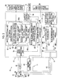
- the processor device 12 includes a base image generation unit 55, a frame memory 56, an image processing unit 57, and a display control circuit 58.
- the controller 59 controls each of the units.
- the base image generation unit 55 generates a base image by performing various kinds of signal processing on the blue signal B, the green signal G, and the red signal R output from the AFE 45 of the electronic endoscope.
- the generated base image is temporarily stored in the frame memory 56.
- the blue signal B, the green signal G, and the red signal R output from the AFE 45 are stored in the frame memory 56.
- the base image may be a pseudo color image obtained by pseudo coloring of blood vessel function information, such as oxygen saturation.
- the image processing unit 57 includes a B/G image generation section 61 (a form of multi-color image generation means), a blood vessel extraction image generation section 63, and a blood vessel enhancement image or suppression image generation section 65 (a form of blood vessel enhancement image or suppression image generation means).
- the B/G image generation section 61 generates a B/G image having a brightness ratio B/G (B/G ratio) between the blue signal B and the green signal G
- B/G ratio indicates a brightness ratio of pixels at the same position between the blue signal B and the green signal G.
- the blood vessel extraction image generation section 63 generates a superficial blood vessel extraction image by extracting the superficial blood vessel based on the B/G image, or generates a medium-deep blood vessel extraction image by extracting the medium-deep blood vessel based on the B/G image.
- the method of generating the blood vessel extraction images differs depending on which of the first to third observation modes is set.
- a superficial blood vessel extraction image or a medium-deep blood vessel extraction image is generated using a first light amount ratio table 63a that is suitable for the first light amount ratio in the first observation mode. Correlation between the brightness ratio B/G and the blood vessel depth shown in Fig. 5 is stored in the first light amount ratio table 63a.
- a form of blood vessel extraction image generation means is configured to include a blood vessel extraction image generation section 63 and the first light amount ratio table 63a to a third light amount ratio table 63c.
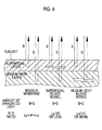
- the percentage of the blue component (B component) of the illumination light is approximately the same as the percentage of the green component (G component) of the illumination light. Therefore, as shown in Fig. 6 , when the illumination light is irradiated to the mucous membrane with no blood vessels, the ratio of the B and G components of the return light is approximately fixed. This is because there is no large light absorption in the mucous membrane. Assuming that the average B/G ratio in this case is P, the B/G ratio in the mucous membrane falls within a fixed range of "Ls to P to Ld".
- Ls is a lower limit of the B/G ratio of the mucous membrane in the first observation mode
- Ld is an upper limit of the B/G ratio of the mucous membrane in the first observation mode.
- the B component of the illumination light When illumination light is irradiated to a superficial blood vessel, the B component of the illumination light is largely absorbed by the superficial blood vessel, while the G component is not absorbed almost. For this reason, the B/G ratio is equal to or less than Ls in most cases. Therefore, it can be seen that the superficial blood vessel is projected to the pixel having a B/G ratio equal to or less than Ls (that is, Ls is a boundary value between the mucous membrane and the superficial blood vessel).
- Ls is a boundary value between the mucous membrane and the superficial blood vessel.
- the B/G ratio is equal to or greater than Ld in most cases. Therefore, it can be seen that the medium-deep blood vessel is projected to the pixel having a B/G ratio equal to or larger than Ld (that is, Ld is a boundary value between the mucous membrane and the medium-deep blood vessel).
- a superficial blood vessel extraction image or a medium-deep blood vessel extraction image is generated using a second light amount ratio table 63b that is suitable for the second light amount ratio in the second observation mode.
- the second light amount ratio table 63b shows a proportional relationship in which the brightness ratio B/G (B/G ratio) increases as the blood vessel depth increases.
- the B/G ratio is generally high.
- a boundary value Ls' between the mucous membrane and the superficial blood vessel is larger than the boundary value Ls in the first observation mode
- a boundary value Ld' between the mucous membrane and the medium-deep blood vessel is larger than the boundary value Ld in the first observation mode
- a superficial blood vessel extraction image or a medium-deep blood vessel extraction image is generated using a third light amount ratio table 63c that is suitable for the third light amount ratio in the third observation mode.
- the third light amount ratio table 63c shows a proportional relationship in which the brightness ratio B/G (B/G ratio) increases as the blood vessel depth increases.
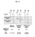
- the B/G ratio is generally low.
- a boundary value Ls" between the mucous membrane and the superficial blood vessel is smaller than the boundary value Ls in the first observation mode
- a boundary value Ld" between the mucous membrane and the medium-deep blood vessel is smaller than the boundary value Ld in the first observation mode
- the blood vessel enhancement image or suppression image generation section 65 generates a superficial blood vessel enhancement image or suppression image, in which a superficial blood vessel is enhanced (or suppressed), by combining the superficial blood vessel extraction image and the base image, and generates a medium-deep blood vessel enhancement image or suppression image, in which a medium-deep blood vessel is enhanced (or suppressed), by combining the medium-deep blood vessel extraction image and the base image.
- a value obtained by increasing the pixel value of each pixel in the superficial blood vessel extraction image (or a medium-deep blood vessel extraction image) several times is added to the pixel value of each pixel of the base image.
- a value obtained by increasing the pixel value of each pixel in the superficial blood vessel extraction image (or a medium-deep blood vessel extraction image) several times is subtracted from the pixel value of each pixel of the base image.
- the display control circuit 58 displays the blood vessel enhancement image or suppression image on the monitor 14 (a form of display means). For example, as shown in Fig. 11 , when a superficial blood vessel 71 extracted from the B/G image is enhanced on the blood vessel enhancement image or suppression image, diagnosis focusing on only the superficial blood vessel 71 is possible since the superficial blood vessel 71 is noticeable compared with a medium-deep blood vessel 72. In contrast, as shown in Fig. 12 , when the medium-deep blood vessel 72 extracted from the B/G image is enhanced on the blood vessel enhancement image or suppression image, diagnosis focusing on only the medium-deep blood vessel 72 is possible since the medium-deep blood vessel 72 is noticeable compared with the superficial blood vessel 71.
- blood vessels are divided into the superficial blood vessel and the medium-deep blood vessel so as to be separately extracted and each of the superficial blood vessel and the medium-deep blood vessel is separately enhanced/suppressed, diagnosis focusing on the superficial blood vessel or diagnosis focusing on the medium-deep blood vessel is possible.
- a predetermined observation mode of the first to third observation modes is set.
- a light amount ratio (light amount ratio between the white light BB and the blue narrowband light BN) corresponding to the predetermined observation mode is set.
- the light amount of the white light BB and the blue narrowband light BN which are emitted from the light source device 13 and are irradiated simultaneously into the subject through the light guide 43, is controlled so as to become the set light amount.
- Reflected light from the subject is imaged by the color CCD 44.
- a base image is generated from the blue signal B, the green signal G, and the red signal R obtained by this imaging.
- the generated base image, the blue signal B, the green signal G, and the red signal R are temporarily stored in the frame memory 56.
- the B/G image generation section 61 generates a B/G image having the brightness ratio B/G between the blue signal B and the green signal G
- a superficial blood vessel extraction image is generated by extracting the superficial blood vessel from the B/G image
- a medium-deep blood vessel extraction image is generated by extracting the medium-deep blood vessel from the B/G image.
- a light amount ratio table corresponding to the set light amount ratio is used for the blood vessel extraction. If the blood vessel extraction image is generated, a blood vessel enhancement image or suppression image in which a superficial blood vessel (or a medium-deep blood vessel) is enhanced/suppressed is generated from the superficial blood vessel extraction image (or the medium-deep blood vessel extraction image) and the base image.
- the generated blood vessel enhancement image or suppression image is converted into a signal, which can be displayed on a monitor, by the display control circuit 58 and is then image-displayed on the monitor 14 as shown in Fig. 11 or 12 .
- the second observation mode is set in which the inside of the subject is observed with illumination light in which the percentage of the blue component is larger than the percentage of the green component
- a pseudo color image in which the superficial blood vessel and the medium-deep blood vessel are displayed in different colors, is displayed on the monitor 14.
- the white light BB is emitted from the broadband light source 30 in the light source device 13.
- fluorescent light may be emitted by providing a phosphor 100 in the distal portion 16a of the electronic endoscope 11 and exciting the phosphor 30b with excitation light from an excitation light source 101 provided in the light source device 13, as shown in Fig. 14 .
- light obtained by combining the fluorescent light and excitation light, which is not absorbed by the phosphor 100 is irradiated into the subject as the white light BB.
- the phosphor 100 is the same as the phosphor 30b of the embodiment described above
- the excitation light source 101 is the same as the excitation light source 30a of the embodiment described above.
- the white light from the phosphor is irradiated into the subject.
- some of a plurality of illumination light beams to illuminate the inside of the subject may be light from a semiconductor light source, and the other light beams may be light wavelength-separated from the white light of a xenon lamp or the like.
- an electronic endoscope system 100 shown in Fig. 15 is used.
- the electronic endoscope system 100 is different from the electronic endoscope system 10 in that an entire light source device 113 is different from the light source device 13 and a CCD 101 of an electronic endoscope 111 is a monochrome CCD.
- the electronic endoscope system 100 has a normal observation mode, in which the inside of the subject is observed with illumination light of three colors of blue light, green light, and red light, and first to third special observation modes, in which the inside of the subject is observed with illumination light of two colors of blue narrowband light and green light.
- the light amount of the blue narrowband light and the light amount of the green light are different in the first to third special observation modes.
- the first special observation mode the light amount of the blue narrowband light and the light amount of the green light are equal.
- the second special observation mode the light amount of the blue narrowband light is larger than the light amount of the green light.
- the third special observation mode the light amount of the green light is larger than the light amount of the blue narrowband light. That is, the first to third special observation modes approximately correspond to the first to third observation modes of the embodiment described above. Therefore, blood vessel extraction methods in the first to third special observation modes are performed in the same manner as in the first to third observation modes. Since others are almost the same as in the embodiment described above, detailed explanation thereof will be omitted.
- the light source device 113 includes a white light source unit 130, a semiconductor light source unit 131, and a light source control unit 132 that drives and controls them.
- the white light source unit 130 includes a lamp body 130a to emit the white light BB and an aperture 130b provided on the optical path of the lamp body 130a.
- the lamp body 130a generates broadband light (white light) BB in which the emission spectrum is continuous in a wide wavelength range from a red region to a blue area (about 400 nm to 700 nm), like a xenon lamp, a halogen lamp, and a metal halide lamp.
- the lamp body 130a is always lit while the light source device 113 is ON.
- the degree of opening of the aperture 130b is adjusted by the driving control of the light source control unit 132.
- the light amount of the white light BB is adjusted by the adjustment of the degree of opening.
- a rotary filter 134 is disposed on the optical path of the white light BB.
- the rotary filter 134 has a disc shape, and is divided into three regions, each of which is a fan-shaped region having a central angle of 120°, in the circumferential direction, and a B filter portion 134a, a G filter portion 134b, and an R filter portion 134c through which light beams of B, G, and R are respectively transmitted are provided in the three regions.
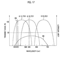
- the B filter portion 134a, the G filter portion 134b, and the R filter portion 134c have spectral transmittances shown in Fig. 17 .
- the B filter portion 134a allows blue light (B color light) of the white light BB to be transmitted therethrough
- the G filter portion 134b allows green light (G color light) of the white light BB to be transmitted therethrough
- the R filter portion 134c allows red light (R color light) of the white light BB to be transmitted therethrough.
- the transmission band of the G filter portion 134b be set such that the center wavelength of the G color light becomes 530 nm. Since the absorption coefficient of hemoglobin is high in a region near the wavelength of 530 nm, it is possible to increase the contrast between blood vessels and other parts by irradiating the blood vessels with light of this wavelength range.
- the rotary filter 134 is rotatably provided so that the B filter portion 134a, the G filter portion 134b, and the R filter portion 134c are selectively inserted into the optical path of the white light BB.
- the rotary filter 134 is rotated, the B filter portion 134a, the G filter portion 134b, and the R filter portion 134c are sequentially inserted into the optical path of the white light BB.
- the semiconductor light source unit 131 includes a blue semiconductor light source 131a, which is a laser diode (LD) or a light emitting diode (LED), and a driving section 131b for driving the blue semiconductor light source 131 a.
- the blue semiconductor light source 131a emits the blue narrowband light BN having a center wavelength of 420 nm (refer to Fig. 17 ). Since the absorption coefficient of hemoglobin is high in a region near the wavelength of 420 nm, it is possible to increase the contrast between blood vessels and other parts by irradiating the blood vessels with light in this wavelength range.
- the driving section 131b is connected to the light source control unit 132.
- the light source control unit 132 adjusts ON/OFF and the amount of light of the blue semiconductor light source 131a by controlling the driving section 131b.
- a laser diode used for the blue semiconductor light source 131a a broad area type InGaN-based laser diode, an InGaNAs-based laser diode, and a GaNAs-based laser diode can be used.
- the light merging section 139 is formed of a dichroic mirror, and allows the B color light, the G color light, and the R color light to be transmitted therethrough as they are and makes the blue narrowband light BN curved by 90° to merge into the optical path of the B color light, the G color light, and the R color light.
- the light transmitted through the light merging section 139 is incident on the light guide 43 through a condensing lens 136.
- a shutter plate 140 is disposed between the rotary filter 134 and the white light source unit 130.
- the shutter plate 40 blocks the white light BB when supplying the blue narrowband light BN to the electronic endoscope 11.
- the shutter plate 140 is a member having a light blocking property for the white light BB, and its planar shape is a shape obtained by cutting a part of a circle.
- the shutter plate 140 has a light blocking portion 140a having a central angle of 240°, and the remaining 120° portion is cut to become a transmission portion 140b through which the white light BB is transmitted.
- the shutter plate 140 is rotatably provided, and the light blocking portion 140a and the transmission portion 140b are inserted alternately selectively into the optical path of the white light BB by rotation.
- the shutter plate 140 has almost the same radius as the rotary filter 134, and the rotation axis matches that of the rotary filter 134.
- the central angle of the transmission portion 140b of the shutter plate 140 is almost the same as that of each of the B filter portion 134a, the G filter portion 134b, and the R filter portion 134c of the rotary filter 34.
- the transmission portion 140b is formed by cutting in this example, the transmission portion 140b may be formed of a transparent plate through which the white light BB is transmitted.
- the rotation of the shutter plate 140 is controlled by the light source control unit 132.
- the rotation control changes with each observation mode.
- the shutter plate 140 In the normal observation mode, the shutter plate 140 is stopped in a state where the light blocking portion 140a is retracted from the optical path of the white light BB and the transmission portion 140b is inserted into the optical path. Accordingly, the white light BB is always incident on the rotary filter 134. Along with this, light beams of three colors of B, G, and R colors are sequentially emitted from the rotary filter 134.
- the blue semiconductor light source 13 is always OFF.
- the shutter plate 140 rotates at the same speed as the rotary filter 134 so that the rotation phase of the transmission portion 140b and the rotation phase of the G filter portion 134b are the same. Accordingly, while the transmission portion 140b is inserted into the optical path of the white light BB and the light blocking portion 140a is retracted from the optical path, the white light BB is transmitted through the G filter portion 134b to generate G color light.
- the G color light is supplied to the electronic endoscope 11 after being transmitted through the condensing lens 136.
- the white light BB is blocked. While the white light BB is blocked, the blue semiconductor light source 131a is turned on to supply the blue narrowband light BN to the electronic endoscope 11. Since the CCD 101 is a monochrome imaging element, color mixing of the white light BB and the blue narrowband light BN is prevented by providing the shutter plate 140.
- the light source control unit 132 controls the degree of opening of the aperture 130b of the white light source unit 130 and the driving section 131b of the semiconductor light source unit 131. By this control, the light amount of the B color light, the G color light, and the R color light from the rotary filter 134 and the light amount of the blue narrowband light BN are adjusted
- the light amount ratio between the G color light and the blue narrowband light BN used in the first to third special observation modes is set in advance for each of the special observation modes.
- the setting of the light amount ratio is performed by a light amount ratio setting section 132a.
- the light amount ratio setting section 132a sets a light amount ratio corresponding to the observation mode selected by the observation mode selection SW 29.
- the first light amount ratio in the first special observation mode is set such that the light amount of the G color light is same as the light amount of the blue narrowband light BN.
- the second light amount ratio in the second special observation mode is set such that the light amount of the blue narrowband light BN is larger than the light amount of the G color light.
- the third light amount ratio in the third special observation mode is set such that the light amount of the G color light is larger than the light amount of the blue narrowband light BN.
- the monochrome CCD 101 and the rotary filter 134 are used. For this reason, the method of controlling the imaging of the CCD 101 and the based image generation method in a base image 55 are different from those in the case of the CCD 44 of the embodiment described above.
- the CCD 101 performs an accumulation operation for accumulating signal charges and a read operation for reading the accumulated signal charges in an acquisition period of one frame.
- image light beams of three colors of B, G, and R are sequentially captured, and the blue signal B, the green signal G, and the red signal R are sequentially output. Then, based on the signals B, G, and R of three colors, a base image is generated. The operations described above are repeatedly performed while the normal observation mode is set.
- the blue signal B is sequentially output by capturing the image light of the blue narrowband light BN for a period of one frame of a period of two frames for which the blue narrowband light BN is irradiated into the subject.
- the green signal B is sequentially output by capturing the image light of the G color light for an irradiation period of one frame for which the G color light is irradiated into the subject. Then, based on the signals B and G of two colors, a base image is generated.
- the operations described above are repeatedly performed while the first to third special observation modes are set.
- light of the semiconductor light source is used as the blue light, and light obtained by wavelength-separating the white light BB is used as the green light.
- light of the semiconductor light source may be used as the green light, and light obtained by wavelength-separating the white light may be used as the blue light.
- medium-deep blood vessels and superficial blood vessels are separated from each other using the B/G ratio.
- the blood vessels can also be separated using calculation values obtained by calculation using two or more color signals having different pieces of color information, such as a G/B ratio, a B-G difference, a G-B difference, a B/(B + G) ratio, a G/(B + G) ratio, a B/R ratio, an R/B ratio, a B-R difference, an R-B difference, and a B/Y ratio.
- the relationship between the calculated value and the blood vessel depth is stored in a plurality of tables corresponding to the first to third observation modes (first to third light amount ratios), and the boundary value of the calculated value indicating the boundary between the mucous membrane and the superficial blood vessel and the boundary value of the calculated value indicating the boundary between the mucous membrane and the medium-deep blood vessel differ depending on each table.
- the B-G difference a value obtained by subtracting the pixel value of the green signal from the pixel value of the blue signal
- the relationship between the B-G difference and the blood vessel depth shown in Fig. 20A is stored in a table that is used in the first observation mode.
- Ls indicates a B-G difference indicating the boundary between the mucous membrane and the superficial blood vessel
- Ld indicates a B-G difference indicating the boundary between the mucous membrane and the medium-deep blood vessel.
- the relationship between the B-G difference and the blood vessel depth shown in Fig. 20B is stored in a table that is used in the second observation mode.
- a B-G difference Ls' at the boundary between the mucous membrane and the superficial blood vessel is set to be larger than Ls
- a B-G difference Ld' at the boundary between the mucous membrane and the medium-deep blood vessel is set to be larger than Ld.
- the relationship between the B-G difference and the blood vessel depth shown in Fig. 20C is stored in a table that is used in the second observation mode.
- a B-G difference Ls" at the boundary between the mucous membrane and the superficial blood vessel is set to be smaller than Ls
- a B-G difference Ld" at the boundary between the mucous membrane and the medium-deep blood vessel is set to be smaller than Ld.
- the G/B ratio is a value obtained by dividing the green signal by the blue signal
- the B-G difference is a value obtained by subtracting the green signal from the blue signal
- the G-B difference is a value obtained by subtracting the blue signal from the green signal
- the B/(B + G) ratio is a value obtained by dividing the blue signal by the sum of the blue signal and the green signal
- the G/(B + G) ratio is a value obtained by dividing the green signal by the sum of the blue signal and the green signal
- the B/R ratio is a value obtained by dividing the blue signal by the red signal
- the R/B ratio is a value obtained by dividing the red signal by the blue signal
- the B-R difference is a value obtained by subtracting the red signal from the blue signal
- the R-B difference is a value obtained by subtracting the blue signal from the red signal
- the B/Y ratio is a value obtained by dividing the green signal by the yellow signal (yellow signal is a signal having wavelength information of 500
Landscapes
- Health & Medical Sciences (AREA)
- Life Sciences & Earth Sciences (AREA)
- Engineering & Computer Science (AREA)
- Surgery (AREA)
- Physics & Mathematics (AREA)
- General Health & Medical Sciences (AREA)
- Medical Informatics (AREA)
- Molecular Biology (AREA)
- Biomedical Technology (AREA)
- Heart & Thoracic Surgery (AREA)
- Pathology (AREA)
- Biophysics (AREA)
- Veterinary Medicine (AREA)
- Public Health (AREA)
- Animal Behavior & Ethology (AREA)
- Radiology & Medical Imaging (AREA)
- Nuclear Medicine, Radiotherapy & Molecular Imaging (AREA)
- Optics & Photonics (AREA)
- General Physics & Mathematics (AREA)
- Theoretical Computer Science (AREA)
- Computer Vision & Pattern Recognition (AREA)
- Quality & Reliability (AREA)
- Signal Processing (AREA)
- Vascular Medicine (AREA)
- Cardiology (AREA)
- Physiology (AREA)
- Multimedia (AREA)
- Endoscopes (AREA)
Abstract
Description
- The present invention relates to an endoscope system capable of extracting blood vessels, such as superficial blood vessels and medium-deep blood vessels, from a subject, a processor device of the endoscope system, and an image processing method.
- In recent medical treatment, diagnosis or the like using an endoscope apparatus has been widely performed. As observation of the inside of a subject using an endoscope apparatus, not only normal observation to observe the subject's inside in its entirety but also special observation to observe a specific part on the subject when the specific part needs to be enhanced has been performed.
- In the aforementioned special observation, determination regarding whether or not cancer is present from the shape of a highlighted blood vessel is performed. Types of blood vessels mainly include superficial blood vessels distributed on a living tissue surface and medium-deep blood vessels located below the superficial blood vessels. Depending on the purpose of diagnosis, diagnosis may be performed focusing on certain blood vessels. In this case, if blood vessels that are not the focus of observation are added in an endoscope image, diagnosis may be interrupted by the blood vessel. For this reason, differentiating superficial blood vessels or medium-deep blood vessels from the image and displaying an image, which is obtained by extracting only blood vessels to be observed, on a monitor has been demanded.
- Regarding the method of determining the depth of a blood vessel,
JP2011-135983A - In recent years, a semiconductor light source, such as a laser light source, have become used as an illumination light source used for normal observation and special observation. For example, in the normal observation, a subject is illuminated with fluorescent light (green to red) that is excited and emitted by irradiating a phosphor with first blue laser light having a center wavelength of 405 nm and second blue laser light having a center wavelength of 445 nm. In the special observation, the ratio between the components of respective colors of illumination light is also changed by adjusting the light amount ratio between the first blue laser light and the second blue laser light. Since the degree of penetration of illumination light into the living tissue has a wavelength dependency, it is possible to change a part to be made clear. For example, when the percentage of a blue component of illumination light is larger than the percentage of a green component by adjusting the light amount ratio, a superficial blood vessel can be made clear. On the contrary, when the green component is larger than the blue component, a medium-deep blood vessel can be made clear.
- Thus, a blood vessel to be observed can be made clear by adjusting the light amount ratio. However, some blood vessels that are not to be observed are slightly displayed although not noticeable. The aforementioned slightly displayed blood vessels reduce the visibility of a blood vessel to be observed. Therefore, it is necessary to distinguish and extract only a blood vessel to be observed. However, if the light amount ratio is adjusted, the hue on the image is changed. For this reason, in the blood vessel discrimination method based on the hue disclosed in
JP2011-135983A - The present invention has been made in view of the above-background, and it is an object of the present invention to provide an endoscope system capable of reliably extracting a plurality of types of blood vessels at different depths even if the ratio between blue and green components of illumination light irradiated to a subject is changed, a processor device of the endoscope system, and an image processing method.
- In order to achieve the above-described object, an endoscope system of the present invention includes: illumination means that includes a light emitting unit, which emits two or more illumination light beams including first illumination light and second illumination light having different wavelength regions, and a light amount ratio setting unit, which sets a light amount ratio between the first illumination light and the second illumination light, and that irradiates a subject with the first illumination light and the second illumination light based on the light amount ratio set by the light amount ratio setting unit; image signal acquisition means for acquiring two or more color signals having different pieces of color information by receiving and imaging return light from the subject using an imaging element; multi-color image generation means for generating a multi-color image formed from calculated values obtained by performing predetermined calculation for each pixel using the two or more color signals; and blood vessel extraction image generation means for generating at least one of a first layer blood vessel extraction image, which is obtained by extracting a first layer blood vessel at a specific depth from the multi-color image, and a second layer blood vessel extraction image, which is obtained by extracting a second layer blood vessel at a position deeper than the first layer blood vessel from the multi-color image, by performing blood vessel extraction processing, which differs depending on the light amount ratio, on the multi-color image.
- Preferably, the light amount ratio setting unit sets one of a plurality of light amount ratios set in advance, and the blood vessel extraction image generation means includes a plurality of calculated value tables, which are set for the plurality of light amount ratios and which store a correlation between a mucous membrane, the first layer blood vessel, and the second layer blood vessel of the subject and the calculated values, and a blood vessel extraction image generation unit that generates at least one of the first layer blood vessel extraction image and the second layer blood vessel extraction image by performing blood vessel extraction processing using a calculated value table corresponding to the light amount ratio set by the light amount ratio setting unit.
- Preferably, in each of the calculated value tables, a calculated value indicating a boundary between the mucous membrane and the first layer blood vessel is stored as a first boundary value, and a calculated value indicating a boundary between the mucous membrane and the second layer blood vessel is stored as a second boundary value. Preferably, the first and second boundary values differ depending on each calculated value table.
- It is preferable to further include blood vessel enhancement image or suppression image generation means for generating a first layer blood vessel enhancement image or suppression image, in which the first layer blood vessel is enhanced or suppressed, using the first layer blood vessel extraction image or generating a second layer blood vessel enhancement image or suppression image, in which the second layer blood vessel is enhanced or suppressed, using the second layer blood vessel extraction image. It is preferable to further include display means for displaying at least one of the first layer blood vessel enhancement image or suppression image and the second layer blood vessel enhancement image or suppression image.
- Preferably, the illumination means irradiates first illumination light, which includes blue excitation light and fluorescent light that is wavelength-converted by a wavelength conversion member using the blue excitation light, and second illumination light, which has a wavelength region in which a center wavelength is on a short wavelength side compared with the excitation light, simultaneously toward the subject. Preferably, the image signal acquisition means images the subject, to which the first illumination light and the second illumination light are irradiated simultaneously, using a color imaging element.
- Preferably, the wavelength conversion member is provided in a separate light source device from an endoscope that irradiates the first illumination light and the second illumination light toward the subject. Preferably, the wavelength conversion member is provided at a distal end of an endoscope that irradiates the first illumination light and the second illumination light toward the subject. Preferably, a center wavelength of the excitation light is 445 nm, and a center wavelength of the second illumination light is 405 nm. Preferably, the first illumination light is illumination light having a center wavelength of 420 nm, and the second illumination light is illumination light having a center wavelength of 530 nm. Preferably, the color signals include a blue signal having information of a blue component and a green signal having information of a green component, and the multi-color image is a B/G image having a B/G ratio obtained by dividing the blue signal by the green signal for each pixel. In addition, the
center wavelength 420 nm of the first illumination light is intended to include a range in which a center wavelength is 420 nm ± 5 nm, and thecenter wavelength 530 nm of the second illumination light is intended to include a range in which a center wavelength is 530 nm ± 5 nm. - Other aspect of the present invention is a processor device of an endoscope system including illumination means, which includes a light emitting unit that emits two or more illumination light beams including first illumination light and second illumination light having different wavelength regions and a light amount ratio setting unit that sets a light amount ratio between the first illumination light and the second illumination light and which irradiates a subject with the first illumination light and the second illumination light based on the light amount ratio set by the light amount ratio setting unit, and an electronic endoscope for acquiring two or more color signals having different pieces of color information by receiving and imaging return light from the subject using an imaging element. The processor device of an endoscope system includes: multi-color image generation means for generating a multi-color image formed from calculated values obtained by performing predetermined calculation for each pixel using the two or more color signals; and blood vessel extraction image generation means for generating at least one of a first layer blood vessel extraction image, which is obtained by extracting a first layer blood vessel at a specific depth from the multi-color image, and a second layer blood vessel extraction image, which is obtained by extracting a second layer blood vessel at a position deeper than the first layer blood vessel from the multi-color image, by performing blood vessel extraction processing, which differs depending on the light amount ratio, on the multi-color image.
- Other aspect of the present invention is an image processing method performed in an endoscope system including illumination means, which includes a light emitting unit that emits two or more illumination light beams including first illumination light and second illumination light having different wavelength regions and a light amount ratio setting unit that sets a light amount ratio between the first illumination light and the second illumination light and which irradiates a subject with the first illumination light and the second illumination light based on the light amount ratio set by the light amount ratio setting unit, and an electronic endoscope for acquiring two or more color signals having different pieces of color information by receiving and imaging return light from the subject using an imaging element. The image processing method includes: generating a multi-color image formed from calculated values obtained by performing predetermined calculation for each pixel using the two or more color signals; and generating at least one of a first layer blood vessel extraction image, which is obtained by extracting a first layer blood vessel at a specific depth from the multi-color image, and a second layer blood vessel extraction image, which is obtained by extracting a second layer blood vessel at a position deeper than the first layer blood vessel from the multi-color image, by performing blood vessel extraction processing, which differs depending on the light amount ratio, on the multi-color image.
- According to the present invention, since blood vessel extraction processing, which differs depending on the light amount ratio of the first illumination light and the second illumination light to illuminate a subject, is performed, it is possible to reliably extract a plurality of types of blood vessels at different depths even if the light amount ratio is changed.
-
-
Fig. 1 is an external view of an electronic endoscope system. -
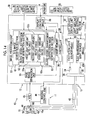
Fig. 2 is a block diagram showing the electrical configuration of the electronic endoscope system. -
Fig. 3 is a graph showing the emission spectra of excitation light having a center wavelength of 445 nm, emitted excitation light that is excited and emitted by applying excitation light to a phosphor, and blue laser light having a center wavelength of 405 nm. -
Fig. 4 is a graph showing the spectral transmittances of color filters of R, G, and B colors. -
Fig. 5 is a graph showing the relationship between the blood vessel depth and the B/G ratio that is stored in a first light amount ratio table. -
Fig. 6 is a diagram for explaining the B/G ratio when illumination light, in which the percentages of the B and G components are approximately the same, is irradiated to the mucous membrane, the superficial blood vessel, and the medium-deep blood vessel. -
Fig. 7 is a graph showing the relationship between the blood vessel depth and the B/G ratio that is stored in a second light amount ratio table. -
Fig. 8 is a diagram for explaining the B/G ratio when illumination light, in which the percentage of the B component is larger than the percentage of the G component, is irradiated to the mucous membrane, the superficial blood vessel, and the medium-deep blood vessel. -
Fig. 9 is a graph showing the relationship between the blood vessel depth and the B/G ratio that is stored in a third light amount ratio table. -
Fig. 10 is a diagram for explaining the B/G ratio when illumination light, in which the percentage of the G component is larger than the percentage of the B component, is irradiated to the mucous membrane, the superficial blood vessel, and the medium-deep blood vessel. -
Fig. 11 is a diagram showing an image in which the superficial blood vessel is enhanced and the medium-deep blood vessel is suppressed. -
Fig. 12 is a diagram showing an image in which the superficial blood vessel is suppressed and the medium-deep blood vessel is enhanced. -
Fig. 13 is a flowchart showing the operation of one embodiment of the present invention. -
Fig. 14 is a block diagram showing the electrical configuration of an electronic endoscope system of an embodiment different from that inFig. 2 . -
Fig. 15 is a block diagram showing the electrical configuration of an endoscope system of an embodiment different from those inFigs. 2 and14 . -
Fig. 16 is a diagram showing a rotary filter. -
Fig. 17 is a graph showing the intensity distribution of blue narrowband light and the spectral transmittances of a B filter, a G filter, and an R filter of the rotary filter. -
Fig. 18 is a diagram showing a shutter plate. -
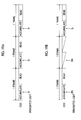
Fig. 19A is a diagram for explaining the imaging control in a normal observation mode, andFig. 19B is a diagram for explaining the imaging control in first to third special observation modes. -
Fig. 20A is a graph showing the relationship between the blood vessel depth and the B-G difference that is stored in a first observation mode table. -
Fig. 20B is a graph showing the relationship between the blood vessel depth and the B-G difference that is stored in a second observation mode table. -
Fig. 20C is a graph showing the relationship between the blood vessel depth and the B-G difference that is stored in a third observation mode table. - As shown in
Fig. 1 , anelectronic endoscope system 10 includes anelectronic endoscope 11 that images the inside of a subject, aprocessor device 12 that generates an endoscope image based on a signal obtained by imaging, alight source device 13 that generates light for illuminating the subject, and amonitor 14 that displays an endoscope image. Theelectronic endoscope 11 includes aflexible insertion unit 16 that is inserted into the body cavity, an operatingunit 17 provided at the proximal end of theinsertion unit 16, and auniversal code 18 that makes a connection between the operatingunit 17 and theprocessor device 12 and thelight source device 13. - The
electronic endoscope system 10 has a function of generating a superficial blood vessel enhancement image or suppression image, in which a superficial blood vessel of a subject is enhanced/suppressed, and a medium-deep blood vessel enhancement image or suppression image, in which a medium-deep superficial blood vessel is enhanced/suppressed. Which blood vessel enhancement image or suppression image is to be generated is determined by the operation of a superficial layer and medium-deep layer selection SW 28 (refer toFig. 2 ). Theelectronic endoscope system 10 has three observation modes of a first observation mode in which the inside of the subject is observed with illumination light in which the percentage of the blue component is approximately the same as the percentage of the green component, a second observation mode in which the inside of the subject is observed with illumination light in which the percentage of the blue component is larger than the percentage of the green component, and a third observation mode in which the inside of the subject is observed with illumination light in which the percentage of the green component is larger than the percentage of the blue component. The first to third observation modes are switched by an observation mode selection SW 29 (refer toFig. 2 ). - A
curved portion 19 obtained by connecting a plurality of curved pieces is formed at the distal end of theinsertion unit 16. Thecurved portion 19 is curved in the horizontal and vertical directions by operating anangle knob 21 of the operating unit. Adistal portion 16a including an optical system for imaging the body cavity and the like is provided at the distal end of thecurved portion 19. Thedistal portion 16a is directed in a desired direction within the body cavity by the bending operation of thecurved portion 19. - A
connector 24 is attached to theuniversal code 18 on the side of theprocessor device 12 and thelight source device 13. Theconnector 24 is a composite connector including a communication connector and a light source connector, and theelectronic endoscope 11 is detachably connected to theprocessor device 12 and thelight source device 13 through theconnector 24. - As shown in
Fig. 2 , the light source device 13 (a form of illumination means) includes abroadband light source 30, a blue narrowbandlight source 33, acoupler 36, and a lightsource control unit 37. Thebroadband light source 30 includes anexcitation light source 30a that emits excitation light having a center wavelength of 445 nm and aphosphor 30b that is excited to emit fluorescent light of green to red due to the excitation light from theexcitation light source 30a. Theexcitation light source 30a is a semiconductor light source, such as a light emitting diode (LED) or a laser diode (LD). As theexcitation light source 30a, a broad area type InGaN-based laser diode can be used. In addition, an InGaNAs-based laser diode, a GaNAs-based laser diode, or the like can also be used. - The
phosphor 30b is configured to contain a plurality of kinds of fluorescent materials (for example, a YAG-based fluorescent material or a fluorescent material, such as BAM (BaMgAl10O17)) that absorb a part of excitation light and are excited to emit light of green to red. Accordingly, by combining the emitted excitation light (fluorescent light) of green to red emitted from thephosphor 30b with excitation light that is transmitted through thephosphor 30b without being absorbed by thephosphor 30b, white light BB (pseudo white light) having an emission spectrum shown inFig. 3 is generated. The generated white light BB is incident on a broadbandoptical fiber 34. - It is preferable that the
phosphor 30b have an approximately rectangular parallelepiped shape. In this case, thephosphor 30b may be formed by solidifying a phosphor material in an approximately rectangular parallelepiped shape using a binder, or may be formed in an approximately rectangular parallelepiped shape by mixing a phosphor material with resin, such as inorganic glass. Thephosphor 30b is also referred to as a Micro White (MW, registered trademark) as a product name. - The blue narrowband
light source 33 is a light emitting diode (LED), a laser diode (LD), or the like. As shown inFig. 3 , the blue narrowbandlight source 33 generates blue narrowband light BN having a limited wavelength of 400 ± 10 nm (center wavelength of 405 nm). The blue narrowband light BN emitted from the blue narrowbandlight source 33 is incident on a narrowbandoptical fiber 35. - The
coupler 36 connects alight guide 43 in theelectronic endoscope 11 to the broadbandoptical fiber 34 and the narrowbandoptical fiber 35. Therefore, both the white light BB and the blue narrowband light BN are simultaneously incident on thelight guide 43. - The light
source control unit 37 controls the light amount of theexcitation light source 30a and the blue narrowbandlight source 33 to maintain the light amount ratio of the white light BB and the blue narrowband light BN constant. The light amount ratio is set by a light amountratio setting section 37a. Since the light amount ratio is set in advance for each of the first to third observation modes, the light amountratio setting section 37a sets a light amount ratio corresponding to the observation mode selected by the observation mode selection SW 29. The first light amount ratio in the first observation mode is set such that the percentage of the blue component of the illumination light irradiated to the subject is approximately the same as the percentage of the green component of the illumination light. When the inside of the subject is illuminated in the first light amount ratio, the subject's inside in its entirety can be brightened, and a portion distributed on the surface, such as a superficial blood vessel, can be made clear. - The second light amount ratio in the second observation mode is set such that the percentage of the blue component of the illumination light is larger than the percentage of the green component of the illumination light. When the inside of the subject is illuminated in the second light amount ratio, both the superficial blood vessel and the medium-deep blood vessel can be made clear. The third light amount ratio in the third observation mode is set such that the percentage of the green component of the illumination light is larger than the percentage of the blue component of the illumination light. When the inside of the subject is illuminated in the third light amount ratio, it is possible to brighten the the subject's inside in its entirety. In addition, when the third light amount ratio is set, it is preferable that the light amount of the blue narrowband light BN be set to about 10% of the maximum light amount.
- The
electronic endoscope 11 includes thelight guide 43, aCCD 44, an analog processing circuit 45 (analog front end: AFE), and animaging control unit 46. Thelight guide 43 is a large-diameter optical fiber, a bundle fiber, or the like, and the incidence end is inserted into thecoupler 36 in the light source device and the exit end is directed toward anirradiation lens 48 provided in thedistal portion 16a. The white light BB and the blue narrowband light BN guided by thelight guide 43 are irradiated into the subject through theirradiation lens 48 and anillumination window 49 attached to the end surface of thedistal portion 16a. The white light BB and the blue narrowband light BN reflected within the subject are incident on a condensinglens 51 through anobservation window 50 attached to the end surface of thedistal portion 16a. - The
CCD 44 receives light from the condensinglens 51 through an imaging surface 44a, performs photoelectric conversion of the received light and accumulates signal charges, and reads the accumulated signal charges as an imaging signal. The read imaging signal is transmitted to anAFE 45. TheCCD 44 is a color CCD, and pixels of three colors of a B pixel in which a color filter of B color is provided, a G pixel in which a color filter of G color is provided, and an R pixel in which a color filter of R color is provided are arrayed on the imaging surface 44a. For theCCD 44, it is preferable to adopt the Bayer array in which the ratio of B, G, and R pixels is 1:2:1. A form of image signal acquisition means is configured to include the condensinglens 51, theCCD 44 having the imaging surface 44a, and theAFE 45. - The color filters of B, G, and R colors have
transmission distributions Fig. 4 . When only the white light BB having a wavelength region of about 400 nm to 700 nm is incident on theCCD 44, the color filters of B, G, and R colors allow light having a wavelength corresponding to thetransmission distributions - The
AFE 45 is configured to include a correlated double sampling circuit (CDS), an automatic gain control circuit (AGC), and an analog/digital converter (A/D) (all not shown). The CDS performs correlated double sampling processing on an imaging signal from theCCD 44 to remove noise caused by the driving of theCCD 44. The AGC amplifies an imaging signal from which noise has been removed by the CDS. The A/D converts an imaging signal amplified by the AGC into a digital imaging signal of a predetermined number of bits, and inputs the digital imaging signal to theprocessor device 12. - The
imaging control unit 46 is connected to acontroller 59 in theprocessor device 12, and transmits a driving signal to theCCD 44 when there is an instruction from thecontroller 59. TheCCD 44 outputs an imaging signal to theAFE 45 at a predetermined frame rate based on the driving signal from theimaging control unit 46. - As shown in
Fig. 2 , theprocessor device 12 includes a baseimage generation unit 55, aframe memory 56, animage processing unit 57, and adisplay control circuit 58. Thecontroller 59 controls each of the units. The baseimage generation unit 55 generates a base image by performing various kinds of signal processing on the blue signal B, the green signal G, and the red signal R output from theAFE 45 of the electronic endoscope. The generated base image is temporarily stored in theframe memory 56. The blue signal B, the green signal G, and the red signal R output from theAFE 45 are stored in theframe memory 56. The base image may be a pseudo color image obtained by pseudo coloring of blood vessel function information, such as oxygen saturation. - The
image processing unit 57 includes a B/G image generation section 61 (a form of multi-color image generation means), a blood vessel extractionimage generation section 63, and a blood vessel enhancement image or suppression image generation section 65 (a form of blood vessel enhancement image or suppression image generation means). The B/Gimage generation section 61 generates a B/G image having a brightness ratio B/G (B/G ratio) between the blue signal B and the green signal G Here, the B/G ratio indicates a brightness ratio of pixels at the same position between the blue signal B and the green signal G. - The blood vessel extraction
image generation section 63 generates a superficial blood vessel extraction image by extracting the superficial blood vessel based on the B/G image, or generates a medium-deep blood vessel extraction image by extracting the medium-deep blood vessel based on the B/G image. The method of generating the blood vessel extraction images differs depending on which of the first to third observation modes is set. When the first observation mode is set, a superficial blood vessel extraction image or a medium-deep blood vessel extraction image is generated using a first light amount ratio table 63a that is suitable for the first light amount ratio in the first observation mode. Correlation between the brightness ratio B/G and the blood vessel depth shown inFig. 5 is stored in the first light amount ratio table 63a. This correlation is a proportional relationship in which the brightness ratio B/G (B/G ratio) increases as the blood vessel depth increases. In addition, a form of blood vessel extraction image generation means is configured to include a blood vessel extractionimage generation section 63 and the first light amount ratio table 63a to a third light amount ratio table 63c. - In the first observation mode, the percentage of the blue component (B component) of the illumination light is approximately the same as the percentage of the green component (G component) of the illumination light. Therefore, as shown in
Fig. 6 , when the illumination light is irradiated to the mucous membrane with no blood vessels, the ratio of the B and G components of the return light is approximately fixed. This is because there is no large light absorption in the mucous membrane. Assuming that the average B/G ratio in this case is P, the B/G ratio in the mucous membrane falls within a fixed range of "Ls to P to Ld". Here, Ls is a lower limit of the B/G ratio of the mucous membrane in the first observation mode, and Ld is an upper limit of the B/G ratio of the mucous membrane in the first observation mode. - When illumination light is irradiated to a superficial blood vessel, the B component of the illumination light is largely absorbed by the superficial blood vessel, while the G component is not absorbed almost. For this reason, the B/G ratio is equal to or less than Ls in most cases. Therefore, it can be seen that the superficial blood vessel is projected to the pixel having a B/G ratio equal to or less than Ls (that is, Ls is a boundary value between the mucous membrane and the superficial blood vessel). On the other hand, when illumination light is irradiated to a medium-deep blood vessel, the G component of the illumination light is largely absorbed by the medium-deep blood vessel, while the B component is not absorbed almost. For this reason, the B/G ratio is equal to or greater than Ld in most cases. Therefore, it can be seen that the medium-deep blood vessel is projected to the pixel having a B/G ratio equal to or larger than Ld (that is, Ld is a boundary value between the mucous membrane and the medium-deep blood vessel).
- Accordingly, when generating a superficial blood vessel extraction image in the first observation mode, only the pixel value of a pixel having a B/G ratio equal to or less than Ls is extracted from the B/G image, and binarization processing for setting the pixel values of other pixels to 0 is performed. On the other hand, when generating a medium-deep blood vessel extraction image, only the pixel value of a pixel having a B/G ratio equal to or greater than Ld is extracted from the B/G image, and binarization processing for setting the pixel values of other pixels to 0 is performed.
- When the second observation mode is set, a superficial blood vessel extraction image or a medium-deep blood vessel extraction image is generated using a second light amount ratio table 63b that is suitable for the second light amount ratio in the second observation mode. As shown in
Fig. 7 , similar to the first light amount ratio table 63a, the second light amount ratio table 63b shows a proportional relationship in which the brightness ratio B/G (B/G ratio) increases as the blood vessel depth increases. In the second observation mode, as shown inFig. 8 , since the percentage of the blue wavelength component (B component) of the illumination light is larger than the percentage of the green wavelength component (G component) of the illumination light, the B/G ratio is generally high. Accordingly, a boundary value Ls' between the mucous membrane and the superficial blood vessel is larger than the boundary value Ls in the first observation mode, and a boundary value Ld' between the mucous membrane and the medium-deep blood vessel is larger than the boundary value Ld in the first observation mode. - Therefore, when generating a superficial blood vessel extraction image in the second observation mode, only the pixel value of a pixel having a B/G ratio equal to or less than Ls' is extracted from the B/G image, and binarization processing for setting the pixel values of other pixels to 0 is performed. On the other hand, when generating a medium-deep blood vessel extraction image, only the pixel value of a pixel having a B/G ratio equal to or greater than Ld' is extracted from the B/G image, and binarization processing for setting the pixel values of other pixels to 0 is performed.
- When the third observation mode is set, a superficial blood vessel extraction image or a medium-deep blood vessel extraction image is generated using a third light amount ratio table 63c that is suitable for the third light amount ratio in the third observation mode. As shown in
Fig. 9 , similar to the first light amount ratio table 63a, the third light amount ratio table 63c shows a proportional relationship in which the brightness ratio B/G (B/G ratio) increases as the blood vessel depth increases. In the third observation mode, as shown inFig. 10 , since the percentage of the green wavelength component (G component) of the illumination light is larger than the percentage of the blue wavelength component (B component) of the illumination light, the B/G ratio is generally low. Accordingly, a boundary value Ls" between the mucous membrane and the superficial blood vessel is smaller than the boundary value Ls in the first observation mode, and a boundary value Ld" between the mucous membrane and the medium-deep blood vessel is smaller than the boundary value Ld in the first observation mode. - Therefore, when generating a superficial blood vessel extraction image in the third observation mode, only the pixel value of a pixel having a B/G ratio equal to or less than Ls" is extracted from the B/G image, and binarization processing for setting the pixel values of other pixels to 0 is performed. On the other hand, when generating a medium-deep blood vessel extraction image, only the pixel value of a pixel having a B/G ratio equal to or greater than Ld" is extracted from the B/G image, and binarization processing for setting the pixel values of other pixels to 0 is performed.
- The blood vessel enhancement image or suppression
image generation section 65 generates a superficial blood vessel enhancement image or suppression image, in which a superficial blood vessel is enhanced (or suppressed), by combining the superficial blood vessel extraction image and the base image, and generates a medium-deep blood vessel enhancement image or suppression image, in which a medium-deep blood vessel is enhanced (or suppressed), by combining the medium-deep blood vessel extraction image and the base image. When enhancing the blood vessel, a value obtained by increasing the pixel value of each pixel in the superficial blood vessel extraction image (or a medium-deep blood vessel extraction image) several times is added to the pixel value of each pixel of the base image. When suppressing the blood vessel, a value obtained by increasing the pixel value of each pixel in the superficial blood vessel extraction image (or a medium-deep blood vessel extraction image) several times is subtracted from the pixel value of each pixel of the base image. - The
display control circuit 58 displays the blood vessel enhancement image or suppression image on the monitor 14 (a form of display means). For example, as shown inFig. 11 , when asuperficial blood vessel 71 extracted from the B/G image is enhanced on the blood vessel enhancement image or suppression image, diagnosis focusing on only thesuperficial blood vessel 71 is possible since thesuperficial blood vessel 71 is noticeable compared with a medium-deep blood vessel 72. In contrast, as shown inFig. 12 , when the medium-deep blood vessel 72 extracted from the B/G image is enhanced on the blood vessel enhancement image or suppression image, diagnosis focusing on only the medium-deep blood vessel 72 is possible since the medium-deep blood vessel 72 is noticeable compared with thesuperficial blood vessel 71. - As described above, by extracting only an image of the blood vessel to be observed from the B/G image and generating a blood vessel enhancement image or suppression image using the extracted blood vessel image, only the blood vessel portion to be observed can be reliably enhanced/suppressed without eliminating the information of portions other than the blood vessel, for example, the information of unevenness of a part to be observed. Therefore, since not only the blood vessel information but also a lot of information useful for diagnosis, such as unevenness of a part to be observed, can be provided to the user, it is possible to improve the diagnostic performance. In addition, since blood vessels are divided into the superficial blood vessel and the medium-deep blood vessel so as to be separately extracted and each of the superficial blood vessel and the medium-deep blood vessel is separately enhanced/suppressed, diagnosis focusing on the superficial blood vessel or diagnosis focusing on the medium-deep blood vessel is possible.
- Next, the operation of one embodiment of the present invention will be described with reference to the flowchart shown in
Fig. 13 . First, a predetermined observation mode of the first to third observation modes is set. Then, a light amount ratio (light amount ratio between the white light BB and the blue narrowband light BN) corresponding to the predetermined observation mode is set. The light amount of the white light BB and the blue narrowband light BN, which are emitted from thelight source device 13 and are irradiated simultaneously into the subject through thelight guide 43, is controlled so as to become the set light amount. Reflected light from the subject is imaged by thecolor CCD 44. A base image is generated from the blue signal B, the green signal G, and the red signal R obtained by this imaging. The generated base image, the blue signal B, the green signal G, and the red signal R are temporarily stored in theframe memory 56. - Then, the B/G
image generation section 61 generates a B/G image having the brightness ratio B/G between the blue signal B and the green signal G A superficial blood vessel extraction image is generated by extracting the superficial blood vessel from the B/G image, and a medium-deep blood vessel extraction image is generated by extracting the medium-deep blood vessel from the B/G image. A light amount ratio table corresponding to the set light amount ratio is used for the blood vessel extraction. If the blood vessel extraction image is generated, a blood vessel enhancement image or suppression image in which a superficial blood vessel (or a medium-deep blood vessel) is enhanced/suppressed is generated from the superficial blood vessel extraction image (or the medium-deep blood vessel extraction image) and the base image. The generated blood vessel enhancement image or suppression image is converted into a signal, which can be displayed on a monitor, by thedisplay control circuit 58 and is then image-displayed on themonitor 14 as shown inFig. 11 or12 . - If the second observation mode is set in which the inside of the subject is observed with illumination light in which the percentage of the blue component is larger than the percentage of the green component, when generating an image for monitor display, it is preferable to assign the blue signal B of the image signals obtained by imaging to B and G channels of the video signal and assign the green signal G to an R channel of the video signal. In this case, a pseudo color image, in which the superficial blood vessel and the medium-deep blood vessel are displayed in different colors, is displayed on the
monitor 14. - In the embodiment described above, the white light BB is emitted from the
broadband light source 30 in thelight source device 13. However, instead of this, fluorescent light may be emitted by providing aphosphor 100 in thedistal portion 16a of theelectronic endoscope 11 and exciting thephosphor 30b with excitation light from anexcitation light source 101 provided in thelight source device 13, as shown inFig. 14 . In this case, light obtained by combining the fluorescent light and excitation light, which is not absorbed by thephosphor 100, is irradiated into the subject as the white light BB. Thephosphor 100 is the same as thephosphor 30b of the embodiment described above, and theexcitation light source 101 is the same as theexcitation light source 30a of the embodiment described above. - In addition, in the embodiment described above, the white light from the phosphor is irradiated into the subject. However, instead of this, some of a plurality of illumination light beams to illuminate the inside of the subject may be light from a semiconductor light source, and the other light beams may be light wavelength-separated from the white light of a xenon lamp or the like. In this case, for example, an
electronic endoscope system 100 shown inFig. 15 is used. - The
electronic endoscope system 100 is different from theelectronic endoscope system 10 in that an entire light source device 113 is different from thelight source device 13 and aCCD 101 of an electronic endoscope 111 is a monochrome CCD. As observation modes, theelectronic endoscope system 100 has a normal observation mode, in which the inside of the subject is observed with illumination light of three colors of blue light, green light, and red light, and first to third special observation modes, in which the inside of the subject is observed with illumination light of two colors of blue narrowband light and green light. - The light amount of the blue narrowband light and the light amount of the green light are different in the first to third special observation modes. In the first special observation mode, the light amount of the blue narrowband light and the light amount of the green light are equal. In the second special observation mode, the light amount of the blue narrowband light is larger than the light amount of the green light. In the third special observation mode, the light amount of the green light is larger than the light amount of the blue narrowband light. That is, the first to third special observation modes approximately correspond to the first to third observation modes of the embodiment described above. Therefore, blood vessel extraction methods in the first to third special observation modes are performed in the same manner as in the first to third observation modes. Since others are almost the same as in the embodiment described above, detailed explanation thereof will be omitted.
- The light source device 113 includes a white
light source unit 130, a semiconductorlight source unit 131, and a lightsource control unit 132 that drives and controls them. The whitelight source unit 130 includes a lamp body 130a to emit the white light BB and anaperture 130b provided on the optical path of the lamp body 130a. - The lamp body 130a generates broadband light (white light) BB in which the emission spectrum is continuous in a wide wavelength range from a red region to a blue area (about 400 nm to 700 nm), like a xenon lamp, a halogen lamp, and a metal halide lamp. The lamp body 130a is always lit while the light source device 113 is ON. The degree of opening of the
aperture 130b is adjusted by the driving control of the lightsource control unit 132. The light amount of the white light BB is adjusted by the adjustment of the degree of opening. - A
rotary filter 134 is disposed on the optical path of the white light BB. As shown inFig. 16 , therotary filter 134 has a disc shape, and is divided into three regions, each of which is a fan-shaped region having a central angle of 120°, in the circumferential direction, and aB filter portion 134a, aG filter portion 134b, and anR filter portion 134c through which light beams of B, G, and R are respectively transmitted are provided in the three regions. - The
B filter portion 134a, theG filter portion 134b, and theR filter portion 134c have spectral transmittances shown inFig. 17 . TheB filter portion 134a allows blue light (B color light) of the white light BB to be transmitted therethrough, theG filter portion 134b allows green light (G color light) of the white light BB to be transmitted therethrough, and theR filter portion 134c allows red light (R color light) of the white light BB to be transmitted therethrough. Here, it is preferable that the transmission band of theG filter portion 134b be set such that the center wavelength of the G color light becomes 530 nm. Since the absorption coefficient of hemoglobin is high in a region near the wavelength of 530 nm, it is possible to increase the contrast between blood vessels and other parts by irradiating the blood vessels with light of this wavelength range. - The
rotary filter 134 is rotatably provided so that theB filter portion 134a, theG filter portion 134b, and theR filter portion 134c are selectively inserted into the optical path of the white light BB. When therotary filter 134 is rotated, theB filter portion 134a, theG filter portion 134b, and theR filter portion 134c are sequentially inserted into the optical path of the white light BB. - The semiconductor
light source unit 131 includes a bluesemiconductor light source 131a, which is a laser diode (LD) or a light emitting diode (LED), and adriving section 131b for driving the bluesemiconductor light source 131 a. The bluesemiconductor light source 131a emits the blue narrowband light BN having a center wavelength of 420 nm (refer toFig. 17 ). Since the absorption coefficient of hemoglobin is high in a region near the wavelength of 420 nm, it is possible to increase the contrast between blood vessels and other parts by irradiating the blood vessels with light in this wavelength range. - The
driving section 131b is connected to the lightsource control unit 132. The lightsource control unit 132 adjusts ON/OFF and the amount of light of the bluesemiconductor light source 131a by controlling thedriving section 131b. As a laser diode used for the bluesemiconductor light source 131a, a broad area type InGaN-based laser diode, an InGaNAs-based laser diode, and a GaNAs-based laser diode can be used. - The B color light, the G color light, and the R color light from the
rotary filter 134 and the blue narrowband light BN from the bluesemiconductor light source 131a merge in alight merging section 139. Thelight merging section 139 is formed of a dichroic mirror, and allows the B color light, the G color light, and the R color light to be transmitted therethrough as they are and makes the blue narrowband light BN curved by 90° to merge into the optical path of the B color light, the G color light, and the R color light. The light transmitted through thelight merging section 139 is incident on thelight guide 43 through a condensinglens 136. - As shown in
Fig. 15 , ashutter plate 140 is disposed between therotary filter 134 and the whitelight source unit 130. The shutter plate 40 blocks the white light BB when supplying the blue narrowband light BN to theelectronic endoscope 11. As shown inFig. 18 , theshutter plate 140 is a member having a light blocking property for the white light BB, and its planar shape is a shape obtained by cutting a part of a circle. - Specifically, the
shutter plate 140 has alight blocking portion 140a having a central angle of 240°, and the remaining 120° portion is cut to become atransmission portion 140b through which the white light BB is transmitted. Theshutter plate 140 is rotatably provided, and thelight blocking portion 140a and thetransmission portion 140b are inserted alternately selectively into the optical path of the white light BB by rotation. - The
shutter plate 140 has almost the same radius as therotary filter 134, and the rotation axis matches that of therotary filter 134. The central angle of thetransmission portion 140b of theshutter plate 140 is almost the same as that of each of theB filter portion 134a, theG filter portion 134b, and theR filter portion 134c of therotary filter 34. Although thetransmission portion 140b is formed by cutting in this example, thetransmission portion 140b may be formed of a transparent plate through which the white light BB is transmitted. - The rotation of the
shutter plate 140 is controlled by the lightsource control unit 132. The rotation control changes with each observation mode. In the normal observation mode, theshutter plate 140 is stopped in a state where thelight blocking portion 140a is retracted from the optical path of the white light BB and thetransmission portion 140b is inserted into the optical path. Accordingly, the white light BB is always incident on therotary filter 134. Along with this, light beams of three colors of B, G, and R colors are sequentially emitted from therotary filter 134. In the normal observation mode, the bluesemiconductor light source 13 is always OFF. - In contrast, in the first to third special observation modes, the
shutter plate 140 rotates at the same speed as therotary filter 134 so that the rotation phase of thetransmission portion 140b and the rotation phase of theG filter portion 134b are the same. Accordingly, while thetransmission portion 140b is inserted into the optical path of the white light BB and thelight blocking portion 140a is retracted from the optical path, the white light BB is transmitted through theG filter portion 134b to generate G color light. The G color light is supplied to theelectronic endoscope 11 after being transmitted through the condensinglens 136. - On the other hand, while the
light blocking portion 140a is inserted into the optical path of the white light BB and thetransmission portion 140b is retracted from the optical path, the white light BB is blocked. While the white light BB is blocked, the bluesemiconductor light source 131a is turned on to supply the blue narrowband light BN to theelectronic endoscope 11. Since theCCD 101 is a monochrome imaging element, color mixing of the white light BB and the blue narrowband light BN is prevented by providing theshutter plate 140. - As described above, the light
source control unit 132 controls the degree of opening of theaperture 130b of the whitelight source unit 130 and thedriving section 131b of the semiconductorlight source unit 131. By this control, the light amount of the B color light, the G color light, and the R color light from therotary filter 134 and the light amount of the blue narrowband light BN are adjusted The light amount ratio between the G color light and the blue narrowband light BN used in the first to third special observation modes is set in advance for each of the special observation modes. As in the embodiment described above, the setting of the light amount ratio is performed by a light amountratio setting section 132a. The light amountratio setting section 132a sets a light amount ratio corresponding to the observation mode selected by the observation mode selection SW 29. - The first light amount ratio in the first special observation mode is set such that the light amount of the G color light is same as the light amount of the blue narrowband light BN. The second light amount ratio in the second special observation mode is set such that the light amount of the blue narrowband light BN is larger than the light amount of the G color light. The third light amount ratio in the third special observation mode is set such that the light amount of the G color light is larger than the light amount of the blue narrowband light BN.
- In the
electronic endoscope system 100, themonochrome CCD 101 and therotary filter 134 are used. For this reason, the method of controlling the imaging of theCCD 101 and the based image generation method in abase image 55 are different from those in the case of theCCD 44 of the embodiment described above. In the normal observation mode, as shown inFig. 19A , theCCD 101 performs an accumulation operation for accumulating signal charges and a read operation for reading the accumulated signal charges in an acquisition period of one frame. In the normal observation mode, image light beams of three colors of B, G, and R are sequentially captured, and the blue signal B, the green signal G, and the red signal R are sequentially output. Then, based on the signals B, G, and R of three colors, a base image is generated. The operations described above are repeatedly performed while the normal observation mode is set. - In contrast, in the first to third special observation modes, as shown in
Fig. 19B , the blue signal B is sequentially output by capturing the image light of the blue narrowband light BN for a period of one frame of a period of two frames for which the blue narrowband light BN is irradiated into the subject. On the other hand, the green signal B is sequentially output by capturing the image light of the G color light for an irradiation period of one frame for which the G color light is irradiated into the subject. Then, based on the signals B and G of two colors, a base image is generated. The operations described above are repeatedly performed while the first to third special observation modes are set. In the first to third special observation mode, when generating a base image, it is preferable to assign the blue signal B to B and G channels for monitor display and assign the green signal G to an R channel for monitor display. - In the
electronic endoscope system 100, in the first to third special observation modes, light of the semiconductor light source is used as the blue light, and light obtained by wavelength-separating the white light BB is used as the green light. In contrast, light of the semiconductor light source may be used as the green light, and light obtained by wavelength-separating the white light may be used as the blue light. - In the embodiment described above, medium-deep blood vessels and superficial blood vessels are separated from each other using the B/G ratio. Instead of this, the blood vessels can also be separated using calculation values obtained by calculation using two or more color signals having different pieces of color information, such as a G/B ratio, a B-G difference, a G-B difference, a B/(B + G) ratio, a G/(B + G) ratio, a B/R ratio, an R/B ratio, a B-R difference, an R-B difference, and a B/Y ratio.
- As in the embodiment described above, the relationship between the calculated value and the blood vessel depth is stored in a plurality of tables corresponding to the first to third observation modes (first to third light amount ratios), and the boundary value of the calculated value indicating the boundary between the mucous membrane and the superficial blood vessel and the boundary value of the calculated value indicating the boundary between the mucous membrane and the medium-deep blood vessel differ depending on each table. For example, in the case of the B-G difference (a value obtained by subtracting the pixel value of the green signal from the pixel value of the blue signal), the relationship between the B-G difference and the blood vessel depth shown in
Fig. 20A is stored in a table that is used in the first observation mode. Here, Ls indicates a B-G difference indicating the boundary between the mucous membrane and the superficial blood vessel, and Ld indicates a B-G difference indicating the boundary between the mucous membrane and the medium-deep blood vessel. - On the other hand, the relationship between the B-G difference and the blood vessel depth shown in
Fig. 20B is stored in a table that is used in the second observation mode. In this table, a B-G difference Ls' at the boundary between the mucous membrane and the superficial blood vessel is set to be larger than Ls, and a B-G difference Ld' at the boundary between the mucous membrane and the medium-deep blood vessel is set to be larger than Ld. In addition, the relationship between the B-G difference and the blood vessel depth shown inFig. 20C is stored in a table that is used in the second observation mode. In this table, a B-G difference Ls" at the boundary between the mucous membrane and the superficial blood vessel is set to be smaller than Ls, and a B-G difference Ld" at the boundary between the mucous membrane and the medium-deep blood vessel is set to be smaller than Ld. - The G/B ratio is a value obtained by dividing the green signal by the blue signal, the B-G difference is a value obtained by subtracting the green signal from the blue signal, the G-B difference is a value obtained by subtracting the blue signal from the green signal, the B/(B + G) ratio is a value obtained by dividing the blue signal by the sum of the blue signal and the green signal, the G/(B + G) ratio is a value obtained by dividing the green signal by the sum of the blue signal and the green signal, the B/R ratio is a value obtained by dividing the blue signal by the red signal, the R/B ratio is a value obtained by dividing the red signal by the blue signal, the B-R difference is a value obtained by subtracting the red signal from the blue signal, the R-B difference is a value obtained by subtracting the blue signal from the red signal, and the B/Y ratio is a value obtained by dividing the green signal by the yellow signal (yellow signal is a signal having wavelength information of 500 nm to 700 nm).
Claims (13)
- An endoscope system, comprising:illumination means that includes a light emitting unit, which emits two or more illumination light beams including first illumination light and second illumination light having different wavelength regions, and a light amount ratio setting unit, which sets a light amount ratio between the first illumination light and the second illumination light, and that irradiates a subject with the first illumination light and the second illumination light based on the light amount ratio set by the light amount ratio setting unit;image signal acquisition means for acquiring two or more color signals having different pieces of color information by receiving and imaging return light from the subject using an imaging element;multi-color image generation means for generating a multi-color image formed from calculated values obtained by performing predetermined calculation for each pixel using the two or more color signals; andblood vessel extraction image generation means for generating at least one of a first layer blood vessel extraction image, which is obtained by extracting a first layer blood vessel at a specific depth from the multi-color image, and a second layer blood vessel extraction image, which is obtained by extracting a second layer blood vessel at a position deeper than the first layer blood vessel from the multi-color image, by performing blood vessel extraction processing, which differs depending on the light amount ratio, on the multi-color image.
- The endoscope system according to claim 1,
wherein the light amount ratio setting unit sets one of a plurality of light amount ratios set in advance, and
the blood vessel extraction image generation means includes a plurality of calculated value tables, which are set for the plurality of light amount ratios and which store a correlation between a mucous membrane, the first layer blood vessel, and the second layer blood vessel of the subject and the calculated values, and a blood vessel extraction image generation unit that generates at least one of the first layer blood vessel extraction image and the second layer blood vessel extraction image by performing blood vessel extraction processing using a calculated value table corresponding to the light amount ratio set by the light amount ratio setting unit. - The endoscope system according to claim 2,
wherein, in each of the calculated value tables, a calculated value indicating a boundary between the mucous membrane and the first layer blood vessel is stored as a first boundary value, and a calculated value indicating a boundary between the mucous membrane and the second layer blood vessel is stored as a second boundary value, and
the first and second boundary values differ depending on each calculated value table. - The endoscope system according to any one of claims 1 to 3, further comprising:blood vessel enhancement image or suppression image generation means for generating a first layer blood vessel enhancement image or suppression image, in which the first layer blood vessel is enhanced or suppressed, using the first layer blood vessel extraction image or generating a second layer blood vessel enhancement image or suppression image, in which the second layer blood vessel is enhanced or suppressed, using the second layer blood vessel extraction image.
- The endoscope system according to claim 4, further comprising:display means for displaying at least one of the first layer blood vessel enhancement image or suppression image and the second layer blood vessel enhancement image or suppression image.
- The endoscope system according to any one of claims 1 to 5,
wherein the illumination means irradiates first illumination light, which includes blue excitation light and fluorescent light that is wavelength-converted by a wavelength conversion member using the blue excitation light, and second illumination light, which has a wavelength region in which a center wavelength is on a short wavelength side compared with the excitation light, simultaneously toward the subject, and
the image signal acquisition means images the subject, to which the first illumination light and the second illumination light are irradiated simultaneously, using a color imaging element. - The endoscope system according to claim 6,
wherein the wavelength conversion member is provided in a separate light source device from an endoscope that irradiates the first illumination light and the second illumination light toward the subject. - The endoscope system according to claim 6,
wherein the wavelength conversion member is provided at a distal end of an endoscope that irradiates the first illumination light and the second illumination light toward the subject. - The endoscope system according to any one of claims 6 to 8,
wherein a center wavelength of the excitation light is 445 nm, and a center wavelength of the second illumination light is 405 nm. - The endoscope system according to any one of claims 1 to 5,
wherein the first illumination light is illumination light having a center wavelength of 420 nm, and the second illumination light is illumination light having a center wavelength of 530 nm. - The endoscope system according to any one of claims 1 to 10,
wherein the color signals include a blue signal having information of a blue component and a green signal having information of a green component, and
the multi-color image is a B/G image having a B/G ratio obtained by dividing the blue signal by the green signal for each pixel. - A processor device of an endoscope system including illumination means, which includes a light emitting unit that emits two or more illumination light beams including first illumination light and second illumination light having different wavelength regions and a light amount ratio setting unit that sets a light amount ratio between the first illumination light and the second illumination light, and which irradiates a subject with the first illumination light and the second illumination light based on the light amount ratio set by the light amount ratio setting unit, and an electronic endoscope for acquiring two or more color signals having different pieces of color information by receiving and imaging return light from the subject using an imaging element, the processor device comprising:multi-color image generation means for generating a multi-color image formed from calculated values obtained by performing predetermined calculation for each pixel using the two or more color signals, andblood vessel extraction image generation means for generating at least one of a first layer blood vessel extraction image, which is obtained by extracting a first layer blood vessel at a specific depth from the multi-color image, and a second layer blood vessel extraction image, which is obtained by extracting a second layer blood vessel at a position deeper than the first layer blood vessel from the multi-color image, by performing blood vessel extraction processing, which differs depending on the light amount ratio, on the multi-color image.
- An image processing method performed in an endoscope system including illumination means, which includes a light emitting unit that emits two or more illumination light beams including first illumination light and second illumination light having different wavelength regions and a light amount ratio setting unit that sets a light amount ratio between the first illumination light and the second illumination light and which irradiates a subject with the first illumination light and the second illumination light based on the light amount ratio set by the light amount ratio setting unit, and an electronic endoscope for acquiring two or more color signals having different pieces of color information by receiving and imaging return light from the subject using an imaging element, the image processing method comprising:generating a multi-color image formed from calculated values obtained by performing predetermined calculation for each pixel using the two or more color signals; andgenerating at least one of a first layer blood vessel extraction image, which is obtained by extracting a first layer blood vessel at a specific depth from the multi-color image, and a second layer blood vessel extraction image, which is obtained by extracting a second layer blood vessel at a position deeper than the first layer blood vessel from the multi-color image, by performing blood vessel extraction processing, which differs depending on the light amount ratio, on the multi-color image.
Applications Claiming Priority (2)
| Application Number | Priority Date | Filing Date | Title |
|---|---|---|---|
| JP2012013317A JP5815426B2 (en) | 2012-01-25 | 2012-01-25 | Endoscope system, processor device for endoscope system, and image processing method |
| PCT/JP2013/050361 WO2013111623A1 (en) | 2012-01-25 | 2013-01-11 | Endoscope system, processor device for endoscope system, and image processing method |
Publications (3)
| Publication Number | Publication Date |
|---|---|
| EP2807973A1 true EP2807973A1 (en) | 2014-12-03 |
| EP2807973A4 EP2807973A4 (en) | 2016-04-20 |
| EP2807973B1 EP2807973B1 (en) | 2019-09-11 |
Family
ID=48873345
Family Applications (1)
| Application Number | Title | Priority Date | Filing Date |
|---|---|---|---|
| EP13741638.4A Active EP2807973B1 (en) | 2012-01-25 | 2013-01-11 | Endoscope system, processor device for endoscope system, and image processing method |
Country Status (5)
| Country | Link |
|---|---|
| US (1) | US9943230B2 (en) |
| EP (1) | EP2807973B1 (en) |
| JP (1) | JP5815426B2 (en) |
| CN (1) | CN104023618B (en) |
| WO (1) | WO2013111623A1 (en) |
Cited By (2)
| Publication number | Priority date | Publication date | Assignee | Title |
|---|---|---|---|---|
| EP3505094A1 (en) * | 2017-12-28 | 2019-07-03 | Ethicon LLC | Use of laser light and red-green-blue coloration to determine properties of back scattered light |
| CN111050629A (en) * | 2017-08-23 | 2020-04-21 | 富士胶片株式会社 | Light source device and endoscope system |
Families Citing this family (163)
| Publication number | Priority date | Publication date | Assignee | Title |
|---|---|---|---|---|
| US11871901B2 (en) | 2012-05-20 | 2024-01-16 | Cilag Gmbh International | Method for situational awareness for surgical network or surgical network connected device capable of adjusting function based on a sensed situation or usage |
| JP5869541B2 (en) * | 2013-09-13 | 2016-02-24 | 富士フイルム株式会社 | ENDOSCOPE SYSTEM, PROCESSOR DEVICE, AND METHOD FOR OPERATING ENDOSCOPE SYSTEM |
| JP6206691B2 (en) * | 2014-03-31 | 2017-10-04 | 富士フイルム株式会社 | Endoscope system and operating method thereof |
| JPWO2016059906A1 (en) * | 2014-10-16 | 2017-04-27 | オリンパス株式会社 | Endoscope device and light source device for endoscope |
| US11504192B2 (en) | 2014-10-30 | 2022-11-22 | Cilag Gmbh International | Method of hub communication with surgical instrument systems |
| JP6432770B2 (en) | 2014-11-12 | 2018-12-05 | ソニー株式会社 | Image processing apparatus, image processing method, and program |
| EP3222194A4 (en) * | 2014-11-20 | 2018-08-01 | Olympus Corporation | Observation apparatus |
| CN107072508B (en) * | 2015-03-25 | 2019-12-20 | 奥林巴斯株式会社 | Observation system |
| JP6640865B2 (en) | 2015-09-29 | 2020-02-05 | 富士フイルム株式会社 | Image processing apparatus, endoscope system, and image processing method |
| CN108135459B (en) * | 2015-10-08 | 2020-11-13 | 奥林巴斯株式会社 | Endoscope device |
| WO2017119239A1 (en) * | 2016-01-08 | 2017-07-13 | Hoya株式会社 | Endoscope device |
| WO2017141417A1 (en) * | 2016-02-19 | 2017-08-24 | Hoya株式会社 | Endoscope light source device |
| JP6488249B2 (en) | 2016-03-08 | 2019-03-20 | 富士フイルム株式会社 | Blood vessel information acquisition apparatus, endoscope system, and blood vessel information acquisition method |
| EP3257432B1 (en) * | 2016-06-17 | 2023-05-10 | FUJIFILM Corporation | Light source device and endoscope system |
| EP3533382A4 (en) * | 2016-10-27 | 2019-12-04 | Fujifilm Corporation | ENDOSCOPIC SYSTEM |
| JP6320592B2 (en) * | 2017-03-21 | 2018-05-09 | 富士フイルム株式会社 | Endoscope system |
| CN110573056B (en) * | 2017-05-02 | 2021-11-30 | 奥林巴斯株式会社 | Endoscope system |
| WO2018229833A1 (en) * | 2017-06-12 | 2018-12-20 | オリンパス株式会社 | Endoscope system |
| US11317919B2 (en) | 2017-10-30 | 2022-05-03 | Cilag Gmbh International | Clip applier comprising a clip crimping system |
| US11911045B2 (en) | 2017-10-30 | 2024-02-27 | Cllag GmbH International | Method for operating a powered articulating multi-clip applier |
| US11026687B2 (en) | 2017-10-30 | 2021-06-08 | Cilag Gmbh International | Clip applier comprising clip advancing systems |
| US11229436B2 (en) | 2017-10-30 | 2022-01-25 | Cilag Gmbh International | Surgical system comprising a surgical tool and a surgical hub |
| US11793537B2 (en) | 2017-10-30 | 2023-10-24 | Cilag Gmbh International | Surgical instrument comprising an adaptive electrical system |
| US11311342B2 (en) | 2017-10-30 | 2022-04-26 | Cilag Gmbh International | Method for communicating with surgical instrument systems |
| US11801098B2 (en) | 2017-10-30 | 2023-10-31 | Cilag Gmbh International | Method of hub communication with surgical instrument systems |
| US11291510B2 (en) | 2017-10-30 | 2022-04-05 | Cilag Gmbh International | Method of hub communication with surgical instrument systems |
| US11564756B2 (en) | 2017-10-30 | 2023-01-31 | Cilag Gmbh International | Method of hub communication with surgical instrument systems |
| US11510741B2 (en) | 2017-10-30 | 2022-11-29 | Cilag Gmbh International | Method for producing a surgical instrument comprising a smart electrical system |
| US11464559B2 (en) | 2017-12-28 | 2022-10-11 | Cilag Gmbh International | Estimating state of ultrasonic end effector and control system therefor |
| US11266468B2 (en) | 2017-12-28 | 2022-03-08 | Cilag Gmbh International | Cooperative utilization of data derived from secondary sources by intelligent surgical hubs |
| US11571234B2 (en) | 2017-12-28 | 2023-02-07 | Cilag Gmbh International | Temperature control of ultrasonic end effector and control system therefor |
| US10966791B2 (en) | 2017-12-28 | 2021-04-06 | Ethicon Llc | Cloud-based medical analytics for medical facility segmented individualization of instrument function |
| US11633237B2 (en) | 2017-12-28 | 2023-04-25 | Cilag Gmbh International | Usage and technique analysis of surgeon / staff performance against a baseline to optimize device utilization and performance for both current and future procedures |
| US11540855B2 (en) | 2017-12-28 | 2023-01-03 | Cilag Gmbh International | Controlling activation of an ultrasonic surgical instrument according to the presence of tissue |
| WO2019133143A1 (en) | 2017-12-28 | 2019-07-04 | Ethicon Llc | Surgical hub and modular device response adjustment based on situational awareness |
| US11045591B2 (en) | 2017-12-28 | 2021-06-29 | Cilag Gmbh International | Dual in-series large and small droplet filters |
| US10892995B2 (en) | 2017-12-28 | 2021-01-12 | Ethicon Llc | Surgical network determination of prioritization of communication, interaction, or processing based on system or device needs |
| US11056244B2 (en) | 2017-12-28 | 2021-07-06 | Cilag Gmbh International | Automated data scaling, alignment, and organizing based on predefined parameters within surgical networks |
| US11419630B2 (en) | 2017-12-28 | 2022-08-23 | Cilag Gmbh International | Surgical system distributed processing |
| US11317937B2 (en) | 2018-03-08 | 2022-05-03 | Cilag Gmbh International | Determining the state of an ultrasonic end effector |
| US11432885B2 (en) | 2017-12-28 | 2022-09-06 | Cilag Gmbh International | Sensing arrangements for robot-assisted surgical platforms |
| US10758310B2 (en) | 2017-12-28 | 2020-09-01 | Ethicon Llc | Wireless pairing of a surgical device with another device within a sterile surgical field based on the usage and situational awareness of devices |
| US11678881B2 (en) | 2017-12-28 | 2023-06-20 | Cilag Gmbh International | Spatial awareness of surgical hubs in operating rooms |
| US11234756B2 (en) | 2017-12-28 | 2022-02-01 | Cilag Gmbh International | Powered surgical tool with predefined adjustable control algorithm for controlling end effector parameter |
| US11026751B2 (en) | 2017-12-28 | 2021-06-08 | Cilag Gmbh International | Display of alignment of staple cartridge to prior linear staple line |
| US10943454B2 (en) | 2017-12-28 | 2021-03-09 | Ethicon Llc | Detection and escalation of security responses of surgical instruments to increasing severity threats |
| US11304745B2 (en) | 2017-12-28 | 2022-04-19 | Cilag Gmbh International | Surgical evacuation sensing and display |
| US20190206569A1 (en) | 2017-12-28 | 2019-07-04 | Ethicon Llc | Method of cloud based data analytics for use with the hub |
| US10918310B2 (en) | 2018-01-03 | 2021-02-16 | Biosense Webster (Israel) Ltd. | Fast anatomical mapping (FAM) using volume filling |
| US10987178B2 (en) | 2017-12-28 | 2021-04-27 | Ethicon Llc | Surgical hub control arrangements |
| US11213359B2 (en) | 2017-12-28 | 2022-01-04 | Cilag Gmbh International | Controllers for robot-assisted surgical platforms |
| US11304763B2 (en) | 2017-12-28 | 2022-04-19 | Cilag Gmbh International | Image capturing of the areas outside the abdomen to improve placement and control of a surgical device in use |
| US11179208B2 (en) | 2017-12-28 | 2021-11-23 | Cilag Gmbh International | Cloud-based medical analytics for security and authentication trends and reactive measures |
| US12062442B2 (en) | 2017-12-28 | 2024-08-13 | Cilag Gmbh International | Method for operating surgical instrument systems |
| US11273001B2 (en) | 2017-12-28 | 2022-03-15 | Cilag Gmbh International | Surgical hub and modular device response adjustment based on situational awareness |
| US11559308B2 (en) | 2017-12-28 | 2023-01-24 | Cilag Gmbh International | Method for smart energy device infrastructure |
| US11304699B2 (en) | 2017-12-28 | 2022-04-19 | Cilag Gmbh International | Method for adaptive control schemes for surgical network control and interaction |
| US11109866B2 (en) | 2017-12-28 | 2021-09-07 | Cilag Gmbh International | Method for circular stapler control algorithm adjustment based on situational awareness |
| US11937769B2 (en) | 2017-12-28 | 2024-03-26 | Cilag Gmbh International | Method of hub communication, processing, storage and display |
| US11202570B2 (en) | 2017-12-28 | 2021-12-21 | Cilag Gmbh International | Communication hub and storage device for storing parameters and status of a surgical device to be shared with cloud based analytics systems |
| US11013563B2 (en) | 2017-12-28 | 2021-05-25 | Ethicon Llc | Drive arrangements for robot-assisted surgical platforms |
| US11612444B2 (en) | 2017-12-28 | 2023-03-28 | Cilag Gmbh International | Adjustment of a surgical device function based on situational awareness |
| US11589888B2 (en) | 2017-12-28 | 2023-02-28 | Cilag Gmbh International | Method for controlling smart energy devices |
| US20190201042A1 (en) | 2017-12-28 | 2019-07-04 | Ethicon Llc | Determining the state of an ultrasonic electromechanical system according to frequency shift |
| US11896443B2 (en) | 2017-12-28 | 2024-02-13 | Cilag Gmbh International | Control of a surgical system through a surgical barrier |
| US11051876B2 (en) | 2017-12-28 | 2021-07-06 | Cilag Gmbh International | Surgical evacuation flow paths |
| US11832840B2 (en) | 2017-12-28 | 2023-12-05 | Cilag Gmbh International | Surgical instrument having a flexible circuit |
| US11253315B2 (en) | 2017-12-28 | 2022-02-22 | Cilag Gmbh International | Increasing radio frequency to create pad-less monopolar loop |
| US12376855B2 (en) | 2017-12-28 | 2025-08-05 | Cilag Gmbh International | Safety systems for smart powered surgical stapling |
| US11308075B2 (en) | 2017-12-28 | 2022-04-19 | Cilag Gmbh International | Surgical network, instrument, and cloud responses based on validation of received dataset and authentication of its source and integrity |
| US11998193B2 (en) | 2017-12-28 | 2024-06-04 | Cilag Gmbh International | Method for usage of the shroud as an aspect of sensing or controlling a powered surgical device, and a control algorithm to adjust its default operation |
| US11304720B2 (en) | 2017-12-28 | 2022-04-19 | Cilag Gmbh International | Activation of energy devices |
| US11278281B2 (en) | 2017-12-28 | 2022-03-22 | Cilag Gmbh International | Interactive surgical system |
| JP2021509061A (en) | 2017-12-28 | 2021-03-18 | エシコン エルエルシーEthicon LLC | Adjusting the function of surgical devices based on situational awareness |
| US11832899B2 (en) | 2017-12-28 | 2023-12-05 | Cilag Gmbh International | Surgical systems with autonomously adjustable control programs |
| US11446052B2 (en) | 2017-12-28 | 2022-09-20 | Cilag Gmbh International | Variation of radio frequency and ultrasonic power level in cooperation with varying clamp arm pressure to achieve predefined heat flux or power applied to tissue |
| US11423007B2 (en) | 2017-12-28 | 2022-08-23 | Cilag Gmbh International | Adjustment of device control programs based on stratified contextual data in addition to the data |
| US20190201090A1 (en) | 2017-12-28 | 2019-07-04 | Ethicon Llc | Capacitive coupled return path pad with separable array elements |
| US11257589B2 (en) | 2017-12-28 | 2022-02-22 | Cilag Gmbh International | Real-time analysis of comprehensive cost of all instrumentation used in surgery utilizing data fluidity to track instruments through stocking and in-house processes |
| US11166772B2 (en) | 2017-12-28 | 2021-11-09 | Cilag Gmbh International | Surgical hub coordination of control and communication of operating room devices |
| US12127729B2 (en) | 2017-12-28 | 2024-10-29 | Cilag Gmbh International | Method for smoke evacuation for surgical hub |
| US11666331B2 (en) | 2017-12-28 | 2023-06-06 | Cilag Gmbh International | Systems for detecting proximity of surgical end effector to cancerous tissue |
| US11969142B2 (en) | 2017-12-28 | 2024-04-30 | Cilag Gmbh International | Method of compressing tissue within a stapling device and simultaneously displaying the location of the tissue within the jaws |
| US11284936B2 (en) | 2017-12-28 | 2022-03-29 | Cilag Gmbh International | Surgical instrument having a flexible electrode |
| US11786251B2 (en) | 2017-12-28 | 2023-10-17 | Cilag Gmbh International | Method for adaptive control schemes for surgical network control and interaction |
| US10595887B2 (en) | 2017-12-28 | 2020-03-24 | Ethicon Llc | Systems for adjusting end effector parameters based on perioperative information |
| US11147607B2 (en) | 2017-12-28 | 2021-10-19 | Cilag Gmbh International | Bipolar combination device that automatically adjusts pressure based on energy modality |
| US20190201112A1 (en) | 2017-12-28 | 2019-07-04 | Ethicon Llc | Computer implemented interactive surgical systems |
| US11602393B2 (en) | 2017-12-28 | 2023-03-14 | Cilag Gmbh International | Surgical evacuation sensing and generator control |
| US11376002B2 (en) | 2017-12-28 | 2022-07-05 | Cilag Gmbh International | Surgical instrument cartridge sensor assemblies |
| US11744604B2 (en) | 2017-12-28 | 2023-09-05 | Cilag Gmbh International | Surgical instrument with a hardware-only control circuit |
| US11069012B2 (en) | 2017-12-28 | 2021-07-20 | Cilag Gmbh International | Interactive surgical systems with condition handling of devices and data capabilities |
| US11076921B2 (en) | 2017-12-28 | 2021-08-03 | Cilag Gmbh International | Adaptive control program updates for surgical hubs |
| US11160605B2 (en) | 2017-12-28 | 2021-11-02 | Cilag Gmbh International | Surgical evacuation sensing and motor control |
| US11419667B2 (en) | 2017-12-28 | 2022-08-23 | Cilag Gmbh International | Ultrasonic energy device which varies pressure applied by clamp arm to provide threshold control pressure at a cut progression location |
| US11659023B2 (en) | 2017-12-28 | 2023-05-23 | Cilag Gmbh International | Method of hub communication |
| US11903601B2 (en) | 2017-12-28 | 2024-02-20 | Cilag Gmbh International | Surgical instrument comprising a plurality of drive systems |
| US11424027B2 (en) | 2017-12-28 | 2022-08-23 | Cilag Gmbh International | Method for operating surgical instrument systems |
| US11291495B2 (en) | 2017-12-28 | 2022-04-05 | Cilag Gmbh International | Interruption of energy due to inadvertent capacitive coupling |
| US12458351B2 (en) | 2017-12-28 | 2025-11-04 | Cilag Gmbh International | Variable output cartridge sensor assembly |
| US11410259B2 (en) | 2017-12-28 | 2022-08-09 | Cilag Gmbh International | Adaptive control program updates for surgical devices |
| US11464535B2 (en) | 2017-12-28 | 2022-10-11 | Cilag Gmbh International | Detection of end effector emersion in liquid |
| US11096693B2 (en) | 2017-12-28 | 2021-08-24 | Cilag Gmbh International | Adjustment of staple height of at least one row of staples based on the sensed tissue thickness or force in closing |
| US11364075B2 (en) | 2017-12-28 | 2022-06-21 | Cilag Gmbh International | Radio frequency energy device for delivering combined electrical signals |
| US12396806B2 (en) | 2017-12-28 | 2025-08-26 | Cilag Gmbh International | Adjustment of a surgical device function based on situational awareness |
| US11389164B2 (en) | 2017-12-28 | 2022-07-19 | Cilag Gmbh International | Method of using reinforced flexible circuits with multiple sensors to optimize performance of radio frequency devices |
| US11771487B2 (en) | 2017-12-28 | 2023-10-03 | Cilag Gmbh International | Mechanisms for controlling different electromechanical systems of an electrosurgical instrument |
| US11132462B2 (en) | 2017-12-28 | 2021-09-28 | Cilag Gmbh International | Data stripping method to interrogate patient records and create anonymized record |
| US11857152B2 (en) | 2017-12-28 | 2024-01-02 | Cilag Gmbh International | Surgical hub spatial awareness to determine devices in operating theater |
| US11559307B2 (en) | 2017-12-28 | 2023-01-24 | Cilag Gmbh International | Method of robotic hub communication, detection, and control |
| US11786245B2 (en) | 2017-12-28 | 2023-10-17 | Cilag Gmbh International | Surgical systems with prioritized data transmission capabilities |
| US11576677B2 (en) | 2017-12-28 | 2023-02-14 | Cilag Gmbh International | Method of hub communication, processing, display, and cloud analytics |
| US11311306B2 (en) | 2017-12-28 | 2022-04-26 | Cilag Gmbh International | Surgical systems for detecting end effector tissue distribution irregularities |
| US11529187B2 (en) | 2017-12-28 | 2022-12-20 | Cilag Gmbh International | Surgical evacuation sensor arrangements |
| US11969216B2 (en) | 2017-12-28 | 2024-04-30 | Cilag Gmbh International | Surgical network recommendations from real time analysis of procedure variables against a baseline highlighting differences from the optimal solution |
| US12096916B2 (en) | 2017-12-28 | 2024-09-24 | Cilag Gmbh International | Method of sensing particulate from smoke evacuated from a patient, adjusting the pump speed based on the sensed information, and communicating the functional parameters of the system to the hub |
| US11896322B2 (en) | 2017-12-28 | 2024-02-13 | Cilag Gmbh International | Sensing the patient position and contact utilizing the mono-polar return pad electrode to provide situational awareness to the hub |
| US11818052B2 (en) | 2017-12-28 | 2023-11-14 | Cilag Gmbh International | Surgical network determination of prioritization of communication, interaction, or processing based on system or device needs |
| US11864728B2 (en) | 2017-12-28 | 2024-01-09 | Cilag Gmbh International | Characterization of tissue irregularities through the use of mono-chromatic light refractivity |
| US11324557B2 (en) | 2017-12-28 | 2022-05-10 | Cilag Gmbh International | Surgical instrument with a sensing array |
| JP6995889B2 (en) * | 2018-01-30 | 2022-01-17 | 富士フイルム株式会社 | Endoscope system and how to operate it |
| US11986233B2 (en) | 2018-03-08 | 2024-05-21 | Cilag Gmbh International | Adjustment of complex impedance to compensate for lost power in an articulating ultrasonic device |
| US12303159B2 (en) | 2018-03-08 | 2025-05-20 | Cilag Gmbh International | Methods for estimating and controlling state of ultrasonic end effector |
| US11259830B2 (en) | 2018-03-08 | 2022-03-01 | Cilag Gmbh International | Methods for controlling temperature in ultrasonic device |
| US11464532B2 (en) | 2018-03-08 | 2022-10-11 | Cilag Gmbh International | Methods for estimating and controlling state of ultrasonic end effector |
| US10973520B2 (en) | 2018-03-28 | 2021-04-13 | Ethicon Llc | Surgical staple cartridge with firing member driven camming assembly that has an onboard tissue cutting feature |
| US11278280B2 (en) | 2018-03-28 | 2022-03-22 | Cilag Gmbh International | Surgical instrument comprising a jaw closure lockout |
| US11207067B2 (en) | 2018-03-28 | 2021-12-28 | Cilag Gmbh International | Surgical stapling device with separate rotary driven closure and firing systems and firing member that engages both jaws while firing |
| US11259806B2 (en) | 2018-03-28 | 2022-03-01 | Cilag Gmbh International | Surgical stapling devices with features for blocking advancement of a camming assembly of an incompatible cartridge installed therein |
| US11471156B2 (en) | 2018-03-28 | 2022-10-18 | Cilag Gmbh International | Surgical stapling devices with improved rotary driven closure systems |
| US11129611B2 (en) | 2018-03-28 | 2021-09-28 | Cilag Gmbh International | Surgical staplers with arrangements for maintaining a firing member thereof in a locked configuration unless a compatible cartridge has been installed therein |
| US11096688B2 (en) | 2018-03-28 | 2021-08-24 | Cilag Gmbh International | Rotary driven firing members with different anvil and channel engagement features |
| US11219453B2 (en) | 2018-03-28 | 2022-01-11 | Cilag Gmbh International | Surgical stapling devices with cartridge compatible closure and firing lockout arrangements |
| US11090047B2 (en) | 2018-03-28 | 2021-08-17 | Cilag Gmbh International | Surgical instrument comprising an adaptive control system |
| WO2019220859A1 (en) * | 2018-05-14 | 2019-11-21 | 富士フイルム株式会社 | Image processing device, endoscope system, and image processing method |
| JP7118147B2 (en) | 2018-06-05 | 2022-08-15 | オリンパス株式会社 | endoscope system |
| JP7093409B2 (en) | 2018-06-05 | 2022-06-29 | オリンパス株式会社 | Endoscope system |
| JP7123135B2 (en) * | 2018-06-19 | 2022-08-22 | オリンパス株式会社 | Endoscope device, operating method and program for endoscope device |
| JP2021191313A (en) * | 2018-06-19 | 2021-12-16 | オリンパス株式会社 | Endoscope system and operation method of endoscope system |
| EP3620098B1 (en) * | 2018-09-07 | 2021-11-03 | Ambu A/S | Enhancing the visibility of blood vessels in colour images |
| CN109199312A (en) * | 2018-09-10 | 2019-01-15 | 苏州新光维医疗科技有限公司 | Adjusting method, device, equipment and the endoscope of light source |
| US11317915B2 (en) | 2019-02-19 | 2022-05-03 | Cilag Gmbh International | Universal cartridge based key feature that unlocks multiple lockout arrangements in different surgical staplers |
| US11369377B2 (en) | 2019-02-19 | 2022-06-28 | Cilag Gmbh International | Surgical stapling assembly with cartridge based retainer configured to unlock a firing lockout |
| US11259807B2 (en) | 2019-02-19 | 2022-03-01 | Cilag Gmbh International | Staple cartridges with cam surfaces configured to engage primary and secondary portions of a lockout of a surgical stapling device |
| US11357503B2 (en) | 2019-02-19 | 2022-06-14 | Cilag Gmbh International | Staple cartridge retainers with frangible retention features and methods of using same |
| US11464511B2 (en) | 2019-02-19 | 2022-10-11 | Cilag Gmbh International | Surgical staple cartridges with movable authentication key arrangements |
| JP2019122865A (en) * | 2019-05-10 | 2019-07-25 | 富士フイルム株式会社 | Endoscope light source device, endoscope system, and method of operating endoscope light source device |
| EP3982813A1 (en) * | 2019-06-13 | 2022-04-20 | Boston Scientific Scimed, Inc. | Methods and apparatus to detect bleeding vessels |
| USD952144S1 (en) | 2019-06-25 | 2022-05-17 | Cilag Gmbh International | Surgical staple cartridge retainer with firing system authentication key |
| USD950728S1 (en) | 2019-06-25 | 2022-05-03 | Cilag Gmbh International | Surgical staple cartridge |
| USD964564S1 (en) | 2019-06-25 | 2022-09-20 | Cilag Gmbh International | Surgical staple cartridge retainer with a closure system authentication key |
| WO2021070688A1 (en) | 2019-10-10 | 2021-04-15 | 富士フイルム株式会社 | Endoscope system and method for operating same |
| JP7324307B2 (en) * | 2019-12-04 | 2023-08-09 | オリンパス株式会社 | Light source device, endoscope system and control method |
| US11166622B2 (en) | 2020-02-21 | 2021-11-09 | Ambu A/S | Video processing apparatus |
| US11109741B1 (en) | 2020-02-21 | 2021-09-07 | Ambu A/S | Video processing apparatus |
| US10835106B1 (en) | 2020-02-21 | 2020-11-17 | Ambu A/S | Portable monitor |
| US10980397B1 (en) * | 2020-02-21 | 2021-04-20 | Ambu A/S | Video processing device |
| CN115209784B (en) * | 2020-03-13 | 2025-12-30 | 奥林巴斯株式会社 | Endoscopic devices, processors, color enhancement methods |
| US11328390B2 (en) | 2020-05-13 | 2022-05-10 | Ambu A/S | Method for adaptive denoising and sharpening and visualization systems implementing the method |
| CN114391792B (en) * | 2021-09-13 | 2023-02-24 | 南京诺源医疗器械有限公司 | Tumor prediction method and device based on narrow-band imaging and imaging endoscope |
| CN115736791B (en) * | 2022-11-28 | 2024-05-07 | 北京大学 | Endoscopic imaging device and method |
| TWI873056B (en) * | 2024-07-01 | 2025-02-11 | 國立成功大學 | Method and computer system for analyzing gastric endoscopic image using image segmentation technology |
| CN119722488B (en) * | 2024-12-19 | 2025-10-21 | 清华大学 | Endoscopic image fusion system and method, image fusion method and device, and equipment |
Family Cites Families (16)
| Publication number | Priority date | Publication date | Assignee | Title |
|---|---|---|---|---|
| US7892169B2 (en) * | 2000-07-21 | 2011-02-22 | Olympus Corporation | Endoscope apparatus |
| JP3583731B2 (en) * | 2000-07-21 | 2004-11-04 | オリンパス株式会社 | Endoscope device and light source device |
| JP2010094152A (en) * | 2008-10-14 | 2010-04-30 | Fujifilm Corp | Electron endoscopic system |
| EP2441374B1 (en) * | 2009-06-10 | 2016-11-16 | Olympus Corporation | Capsule endoscope device |
| JP5767775B2 (en) * | 2009-07-06 | 2015-08-19 | 富士フイルム株式会社 | Endoscope device |
| JP5401205B2 (en) * | 2009-08-10 | 2014-01-29 | 富士フイルム株式会社 | Endoscope device |
| JP5460507B2 (en) * | 2009-09-24 | 2014-04-02 | 富士フイルム株式会社 | Endoscope apparatus operating method and endoscope apparatus |
| JP5389742B2 (en) * | 2009-09-30 | 2014-01-15 | 富士フイルム株式会社 | Electronic endoscope system, processor device for electronic endoscope, and method for operating electronic endoscope system |
| US8668636B2 (en) * | 2009-09-30 | 2014-03-11 | Fujifilm Corporation | Electronic endoscope system, processor for electronic endoscope, and method of displaying vascular information |
| JP5389612B2 (en) * | 2009-11-06 | 2014-01-15 | 富士フイルム株式会社 | Electronic endoscope system, processor device for electronic endoscope, and method for operating electronic endoscope system |
| JP5541914B2 (en) | 2009-12-28 | 2014-07-09 | オリンパス株式会社 | Image processing apparatus, electronic apparatus, program, and operation method of endoscope apparatus |
| JP2011156339A (en) * | 2010-01-08 | 2011-08-18 | Fujifilm Corp | Medical apparatus and endoscope apparatus |
| JP5457247B2 (en) * | 2010-03-26 | 2014-04-02 | 富士フイルム株式会社 | Electronic endoscope system, processor device for electronic endoscope, and method for operating electronic endoscope system |
| JP5395725B2 (en) * | 2010-04-05 | 2014-01-22 | 富士フイルム株式会社 | Electronic endoscope system |
| JP2012000160A (en) * | 2010-06-14 | 2012-01-05 | Fujifilm Corp | Endoscope apparatus |
| JP5496075B2 (en) * | 2010-12-27 | 2014-05-21 | 富士フイルム株式会社 | Endoscopic diagnosis device |
-
2012
- 2012-01-25 JP JP2012013317A patent/JP5815426B2/en active Active
-
2013
- 2013-01-11 WO PCT/JP2013/050361 patent/WO2013111623A1/en not_active Ceased
- 2013-01-11 EP EP13741638.4A patent/EP2807973B1/en active Active
- 2013-01-11 CN CN201380004495.9A patent/CN104023618B/en active Active
-
2014
- 2014-07-01 US US14/321,116 patent/US9943230B2/en active Active
Cited By (2)
| Publication number | Priority date | Publication date | Assignee | Title |
|---|---|---|---|---|
| CN111050629A (en) * | 2017-08-23 | 2020-04-21 | 富士胶片株式会社 | Light source device and endoscope system |
| EP3505094A1 (en) * | 2017-12-28 | 2019-07-03 | Ethicon LLC | Use of laser light and red-green-blue coloration to determine properties of back scattered light |
Also Published As
| Publication number | Publication date |
|---|---|
| CN104023618B (en) | 2016-04-20 |
| JP5815426B2 (en) | 2015-11-17 |
| US9943230B2 (en) | 2018-04-17 |
| JP2013150713A (en) | 2013-08-08 |
| EP2807973A4 (en) | 2016-04-20 |
| US20140316283A1 (en) | 2014-10-23 |
| CN104023618A (en) | 2014-09-03 |
| EP2807973B1 (en) | 2019-09-11 |
| WO2013111623A1 (en) | 2013-08-01 |
Similar Documents
| Publication | Publication Date | Title |
|---|---|---|
| EP2807973B1 (en) | Endoscope system, processor device for endoscope system, and image processing method | |
| EP2813172B1 (en) | Endoscope system, processor device for endoscope system, and image processing method | |
| EP2754379B1 (en) | Endoscope system and image display method | |
| JP5303012B2 (en) | Endoscope system, processor device for endoscope system, and method for operating endoscope system | |
| US9456738B2 (en) | Endoscopic diagnosis system | |
| JP6005303B2 (en) | Fluorescence observation endoscope system | |
| JP5331904B2 (en) | Endoscope system and method for operating endoscope system | |
| JP5457247B2 (en) | Electronic endoscope system, processor device for electronic endoscope, and method for operating electronic endoscope system | |
| JP5496852B2 (en) | Electronic endoscope system, processor device for electronic endoscope system, and method for operating electronic endoscope system | |
| EP2474265B1 (en) | Endoscope diagnosis system | |
| EP2465433A1 (en) | Endoscope apparatus | |
| CN109381154B (en) | Endoscope system | |
| JP2012005807A (en) | Method of controlling endoscope apparatus and endoscope apparatus | |
| JP2012029703A (en) | Method for controlling endoscope apparatus, and endoscope apparatus | |
| US9596982B2 (en) | Endoscope system and composite image generation method | |
| JP2013099464A (en) | Endoscope system, processor device in endoscope system, and image display method | |
| US9788709B2 (en) | Endoscope system and image generation method to generate images associated with irregularities of a subject | |
| EP2666403A1 (en) | Endoscope system and processor device thereof, and image producing method | |
| JP6277068B2 (en) | Endoscope light source device and endoscope system | |
| JP2015231576A (en) | Endoscope system, processor device for endoscope system, and image processing method | |
| JP5965028B2 (en) | Endoscope system | |
| JP6970777B2 (en) | Endoscope system | |
| JP2022009755A (en) | Endoscope system |
Legal Events
| Date | Code | Title | Description |
|---|---|---|---|
| PUAI | Public reference made under article 153(3) epc to a published international application that has entered the european phase |
Free format text: ORIGINAL CODE: 0009012 |
|
| 17P | Request for examination filed |
Effective date: 20140625 |
|
| AK | Designated contracting states |
Kind code of ref document: A1 Designated state(s): AL AT BE BG CH CY CZ DE DK EE ES FI FR GB GR HR HU IE IS IT LI LT LU LV MC MK MT NL NO PL PT RO RS SE SI SK SM TR |
|
| DAX | Request for extension of the european patent (deleted) | ||
| RIN1 | Information on inventor provided before grant (corrected) |
Inventor name: KAKU,TOSHIHIKO Inventor name: IIDA, TAKAYUKI |
|
| RA4 | Supplementary search report drawn up and despatched (corrected) |
Effective date: 20160317 |
|
| RIC1 | Information provided on ipc code assigned before grant |
Ipc: A61B 1/04 20060101AFI20160311BHEP Ipc: A61B 1/06 20060101ALI20160311BHEP Ipc: A61B 1/00 20060101ALI20160311BHEP Ipc: G06T 7/00 20060101ALI20160311BHEP Ipc: G06K 9/00 20060101ALI20160311BHEP Ipc: G06T 7/40 20060101ALI20160311BHEP Ipc: A61B 5/00 20060101ALI20160311BHEP Ipc: A61B 5/02 20060101ALI20160311BHEP |
|
| STAA | Information on the status of an ep patent application or granted ep patent |
Free format text: STATUS: EXAMINATION IS IN PROGRESS |
|
| 17Q | First examination report despatched |
Effective date: 20180710 |
|
| REG | Reference to a national code |
Ref country code: DE Ref legal event code: R079 Ref document number: 602013060371 Country of ref document: DE Free format text: PREVIOUS MAIN CLASS: A61B0001040000 Ipc: A61B0001000000 |
|
| RIC1 | Information provided on ipc code assigned before grant |
Ipc: A61B 5/02 20060101ALI20190221BHEP Ipc: A61B 5/00 20060101ALI20190221BHEP Ipc: A61B 1/00 20060101AFI20190221BHEP Ipc: G06K 9/00 20060101ALI20190221BHEP Ipc: A61B 1/06 20060101ALI20190221BHEP Ipc: G06T 7/00 20170101ALI20190221BHEP Ipc: G06T 7/90 20170101ALI20190221BHEP Ipc: A61B 1/04 20060101ALI20190221BHEP |
|
| GRAP | Despatch of communication of intention to grant a patent |
Free format text: ORIGINAL CODE: EPIDOSNIGR1 |
|
| STAA | Information on the status of an ep patent application or granted ep patent |
Free format text: STATUS: GRANT OF PATENT IS INTENDED |
|
| INTG | Intention to grant announced |
Effective date: 20190409 |
|
| GRAS | Grant fee paid |
Free format text: ORIGINAL CODE: EPIDOSNIGR3 |
|
| GRAA | (expected) grant |
Free format text: ORIGINAL CODE: 0009210 |
|
| STAA | Information on the status of an ep patent application or granted ep patent |
Free format text: STATUS: THE PATENT HAS BEEN GRANTED |
|
| AK | Designated contracting states |
Kind code of ref document: B1 Designated state(s): AL AT BE BG CH CY CZ DE DK EE ES FI FR GB GR HR HU IE IS IT LI LT LU LV MC MK MT NL NO PL PT RO RS SE SI SK SM TR |
|
| REG | Reference to a national code |
Ref country code: GB Ref legal event code: FG4D |
|
| REG | Reference to a national code |
Ref country code: CH Ref legal event code: EP |
|
| REG | Reference to a national code |
Ref country code: AT Ref legal event code: REF Ref document number: 1177410 Country of ref document: AT Kind code of ref document: T Effective date: 20190915 |
|
| REG | Reference to a national code |
Ref country code: DE Ref legal event code: R096 Ref document number: 602013060371 Country of ref document: DE |
|
| REG | Reference to a national code |
Ref country code: IE Ref legal event code: FG4D |
|
| REG | Reference to a national code |
Ref country code: NL Ref legal event code: MP Effective date: 20190911 |
|
| REG | Reference to a national code |
Ref country code: LT Ref legal event code: MG4D |
|
| PG25 | Lapsed in a contracting state [announced via postgrant information from national office to epo] |
Ref country code: NO Free format text: LAPSE BECAUSE OF FAILURE TO SUBMIT A TRANSLATION OF THE DESCRIPTION OR TO PAY THE FEE WITHIN THE PRESCRIBED TIME-LIMIT Effective date: 20191211 Ref country code: BG Free format text: LAPSE BECAUSE OF FAILURE TO SUBMIT A TRANSLATION OF THE DESCRIPTION OR TO PAY THE FEE WITHIN THE PRESCRIBED TIME-LIMIT Effective date: 20191211 Ref country code: LT Free format text: LAPSE BECAUSE OF FAILURE TO SUBMIT A TRANSLATION OF THE DESCRIPTION OR TO PAY THE FEE WITHIN THE PRESCRIBED TIME-LIMIT Effective date: 20190911 Ref country code: HR Free format text: LAPSE BECAUSE OF FAILURE TO SUBMIT A TRANSLATION OF THE DESCRIPTION OR TO PAY THE FEE WITHIN THE PRESCRIBED TIME-LIMIT Effective date: 20190911 Ref country code: FI Free format text: LAPSE BECAUSE OF FAILURE TO SUBMIT A TRANSLATION OF THE DESCRIPTION OR TO PAY THE FEE WITHIN THE PRESCRIBED TIME-LIMIT Effective date: 20190911 Ref country code: SE Free format text: LAPSE BECAUSE OF FAILURE TO SUBMIT A TRANSLATION OF THE DESCRIPTION OR TO PAY THE FEE WITHIN THE PRESCRIBED TIME-LIMIT Effective date: 20190911 |
|
| PG25 | Lapsed in a contracting state [announced via postgrant information from national office to epo] |
Ref country code: AL Free format text: LAPSE BECAUSE OF FAILURE TO SUBMIT A TRANSLATION OF THE DESCRIPTION OR TO PAY THE FEE WITHIN THE PRESCRIBED TIME-LIMIT Effective date: 20190911 Ref country code: GR Free format text: LAPSE BECAUSE OF FAILURE TO SUBMIT A TRANSLATION OF THE DESCRIPTION OR TO PAY THE FEE WITHIN THE PRESCRIBED TIME-LIMIT Effective date: 20191212 Ref country code: RS Free format text: LAPSE BECAUSE OF FAILURE TO SUBMIT A TRANSLATION OF THE DESCRIPTION OR TO PAY THE FEE WITHIN THE PRESCRIBED TIME-LIMIT Effective date: 20190911 Ref country code: LV Free format text: LAPSE BECAUSE OF FAILURE TO SUBMIT A TRANSLATION OF THE DESCRIPTION OR TO PAY THE FEE WITHIN THE PRESCRIBED TIME-LIMIT Effective date: 20190911 Ref country code: ES Free format text: LAPSE BECAUSE OF FAILURE TO SUBMIT A TRANSLATION OF THE DESCRIPTION OR TO PAY THE FEE WITHIN THE PRESCRIBED TIME-LIMIT Effective date: 20190911 |
|
| REG | Reference to a national code |
Ref country code: AT Ref legal event code: MK05 Ref document number: 1177410 Country of ref document: AT Kind code of ref document: T Effective date: 20190911 |
|
| PG25 | Lapsed in a contracting state [announced via postgrant information from national office to epo] |
Ref country code: IT Free format text: LAPSE BECAUSE OF FAILURE TO SUBMIT A TRANSLATION OF THE DESCRIPTION OR TO PAY THE FEE WITHIN THE PRESCRIBED TIME-LIMIT Effective date: 20190911 Ref country code: RO Free format text: LAPSE BECAUSE OF FAILURE TO SUBMIT A TRANSLATION OF THE DESCRIPTION OR TO PAY THE FEE WITHIN THE PRESCRIBED TIME-LIMIT Effective date: 20190911 Ref country code: AT Free format text: LAPSE BECAUSE OF FAILURE TO SUBMIT A TRANSLATION OF THE DESCRIPTION OR TO PAY THE FEE WITHIN THE PRESCRIBED TIME-LIMIT Effective date: 20190911 Ref country code: NL Free format text: LAPSE BECAUSE OF FAILURE TO SUBMIT A TRANSLATION OF THE DESCRIPTION OR TO PAY THE FEE WITHIN THE PRESCRIBED TIME-LIMIT Effective date: 20190911 Ref country code: PL Free format text: LAPSE BECAUSE OF FAILURE TO SUBMIT A TRANSLATION OF THE DESCRIPTION OR TO PAY THE FEE WITHIN THE PRESCRIBED TIME-LIMIT Effective date: 20190911 Ref country code: EE Free format text: LAPSE BECAUSE OF FAILURE TO SUBMIT A TRANSLATION OF THE DESCRIPTION OR TO PAY THE FEE WITHIN THE PRESCRIBED TIME-LIMIT Effective date: 20190911 Ref country code: PT Free format text: LAPSE BECAUSE OF FAILURE TO SUBMIT A TRANSLATION OF THE DESCRIPTION OR TO PAY THE FEE WITHIN THE PRESCRIBED TIME-LIMIT Effective date: 20200113 |
|
| PG25 | Lapsed in a contracting state [announced via postgrant information from national office to epo] |
Ref country code: IS Free format text: LAPSE BECAUSE OF FAILURE TO SUBMIT A TRANSLATION OF THE DESCRIPTION OR TO PAY THE FEE WITHIN THE PRESCRIBED TIME-LIMIT Effective date: 20200224 Ref country code: CZ Free format text: LAPSE BECAUSE OF FAILURE TO SUBMIT A TRANSLATION OF THE DESCRIPTION OR TO PAY THE FEE WITHIN THE PRESCRIBED TIME-LIMIT Effective date: 20190911 Ref country code: SK Free format text: LAPSE BECAUSE OF FAILURE TO SUBMIT A TRANSLATION OF THE DESCRIPTION OR TO PAY THE FEE WITHIN THE PRESCRIBED TIME-LIMIT Effective date: 20190911 Ref country code: SM Free format text: LAPSE BECAUSE OF FAILURE TO SUBMIT A TRANSLATION OF THE DESCRIPTION OR TO PAY THE FEE WITHIN THE PRESCRIBED TIME-LIMIT Effective date: 20190911 |
|
| REG | Reference to a national code |
Ref country code: DE Ref legal event code: R097 Ref document number: 602013060371 Country of ref document: DE |
|
| PLBE | No opposition filed within time limit |
Free format text: ORIGINAL CODE: 0009261 |
|
| STAA | Information on the status of an ep patent application or granted ep patent |
Free format text: STATUS: NO OPPOSITION FILED WITHIN TIME LIMIT |
|
| PG2D | Information on lapse in contracting state deleted |
Ref country code: IS |
|
| PG25 | Lapsed in a contracting state [announced via postgrant information from national office to epo] |
Ref country code: DK Free format text: LAPSE BECAUSE OF FAILURE TO SUBMIT A TRANSLATION OF THE DESCRIPTION OR TO PAY THE FEE WITHIN THE PRESCRIBED TIME-LIMIT Effective date: 20190911 Ref country code: IS Free format text: LAPSE BECAUSE OF FAILURE TO SUBMIT A TRANSLATION OF THE DESCRIPTION OR TO PAY THE FEE WITHIN THE PRESCRIBED TIME-LIMIT Effective date: 20200112 |
|
| 26N | No opposition filed |
Effective date: 20200615 |
|
| PG25 | Lapsed in a contracting state [announced via postgrant information from national office to epo] |
Ref country code: SI Free format text: LAPSE BECAUSE OF FAILURE TO SUBMIT A TRANSLATION OF THE DESCRIPTION OR TO PAY THE FEE WITHIN THE PRESCRIBED TIME-LIMIT Effective date: 20190911 Ref country code: MC Free format text: LAPSE BECAUSE OF FAILURE TO SUBMIT A TRANSLATION OF THE DESCRIPTION OR TO PAY THE FEE WITHIN THE PRESCRIBED TIME-LIMIT Effective date: 20190911 |
|
| REG | Reference to a national code |
Ref country code: CH Ref legal event code: PL |
|
| GBPC | Gb: european patent ceased through non-payment of renewal fee |
Effective date: 20200111 |
|
| REG | Reference to a national code |
Ref country code: BE Ref legal event code: MM Effective date: 20200131 |
|
| PG25 | Lapsed in a contracting state [announced via postgrant information from national office to epo] |
Ref country code: FR Free format text: LAPSE BECAUSE OF NON-PAYMENT OF DUE FEES Effective date: 20200131 Ref country code: LU Free format text: LAPSE BECAUSE OF NON-PAYMENT OF DUE FEES Effective date: 20200111 Ref country code: GB Free format text: LAPSE BECAUSE OF NON-PAYMENT OF DUE FEES Effective date: 20200111 |
|
| PG25 | Lapsed in a contracting state [announced via postgrant information from national office to epo] |
Ref country code: CH Free format text: LAPSE BECAUSE OF NON-PAYMENT OF DUE FEES Effective date: 20200131 Ref country code: BE Free format text: LAPSE BECAUSE OF NON-PAYMENT OF DUE FEES Effective date: 20200131 Ref country code: LI Free format text: LAPSE BECAUSE OF NON-PAYMENT OF DUE FEES Effective date: 20200131 |
|
| PG25 | Lapsed in a contracting state [announced via postgrant information from national office to epo] |
Ref country code: IE Free format text: LAPSE BECAUSE OF NON-PAYMENT OF DUE FEES Effective date: 20200111 |
|
| PG25 | Lapsed in a contracting state [announced via postgrant information from national office to epo] |
Ref country code: TR Free format text: LAPSE BECAUSE OF FAILURE TO SUBMIT A TRANSLATION OF THE DESCRIPTION OR TO PAY THE FEE WITHIN THE PRESCRIBED TIME-LIMIT Effective date: 20190911 Ref country code: MT Free format text: LAPSE BECAUSE OF FAILURE TO SUBMIT A TRANSLATION OF THE DESCRIPTION OR TO PAY THE FEE WITHIN THE PRESCRIBED TIME-LIMIT Effective date: 20190911 Ref country code: CY Free format text: LAPSE BECAUSE OF FAILURE TO SUBMIT A TRANSLATION OF THE DESCRIPTION OR TO PAY THE FEE WITHIN THE PRESCRIBED TIME-LIMIT Effective date: 20190911 |
|
| PG25 | Lapsed in a contracting state [announced via postgrant information from national office to epo] |
Ref country code: MK Free format text: LAPSE BECAUSE OF FAILURE TO SUBMIT A TRANSLATION OF THE DESCRIPTION OR TO PAY THE FEE WITHIN THE PRESCRIBED TIME-LIMIT Effective date: 20190911 |
|
| P01 | Opt-out of the competence of the unified patent court (upc) registered |
Effective date: 20230515 |
|
| PGFP | Annual fee paid to national office [announced via postgrant information from national office to epo] |
Ref country code: DE Payment date: 20251203 Year of fee payment: 14 |