EP2807629B1 - Mobile device configured to compute 3d models based on motion sensor data - Google Patents
Mobile device configured to compute 3d models based on motion sensor data Download PDFInfo
- Publication number
- EP2807629B1 EP2807629B1 EP12806819.4A EP12806819A EP2807629B1 EP 2807629 B1 EP2807629 B1 EP 2807629B1 EP 12806819 A EP12806819 A EP 12806819A EP 2807629 B1 EP2807629 B1 EP 2807629B1
- Authority
- EP
- European Patent Office
- Prior art keywords
- image
- mobile device
- camera
- model
- feature points
- Prior art date
- Legal status (The legal status is an assumption and is not a legal conclusion. Google has not performed a legal analysis and makes no representation as to the accuracy of the status listed.)
- Active
Links
Images


Classifications
-
- G—PHYSICS
- G06—COMPUTING OR CALCULATING; COUNTING
- G06T—IMAGE DATA PROCESSING OR GENERATION, IN GENERAL
- G06T7/00—Image analysis
- G06T7/50—Depth or shape recovery
- G06T7/55—Depth or shape recovery from multiple images
- G06T7/564—Depth or shape recovery from multiple images from contours
-
- G—PHYSICS
- G06—COMPUTING OR CALCULATING; COUNTING
- G06T—IMAGE DATA PROCESSING OR GENERATION, IN GENERAL
- G06T7/00—Image analysis
- G06T7/50—Depth or shape recovery
- G06T7/55—Depth or shape recovery from multiple images
- G06T7/579—Depth or shape recovery from multiple images from motion
-
- H—ELECTRICITY
- H04—ELECTRIC COMMUNICATION TECHNIQUE
- H04N—PICTORIAL COMMUNICATION, e.g. TELEVISION
- H04N13/00—Stereoscopic video systems; Multi-view video systems; Details thereof
- H04N13/20—Image signal generators
- H04N13/204—Image signal generators using stereoscopic image cameras
- H04N13/207—Image signal generators using stereoscopic image cameras using a single two-dimensional [2D] image sensor
-
- G—PHYSICS
- G06—COMPUTING OR CALCULATING; COUNTING
- G06T—IMAGE DATA PROCESSING OR GENERATION, IN GENERAL
- G06T2207/00—Indexing scheme for image analysis or image enhancement
- G06T2207/10—Image acquisition modality
- G06T2207/10016—Video; Image sequence
Definitions
- the present disclosure is generally related to generating three-dimensional (3D) models of objects.
- wireless computing devices such as portable wireless telephones, personal digital assistants (PDAs), and paging devices that are small, lightweight, and easily carried by users.
- portable wireless telephones such as cellular telephones and internet protocol (IP) telephones
- IP internet protocol
- wireless telephones can communicate voice and data packets over wireless networks.
- wireless telephones can process executable instructions, including software applications, such as a web browser application, that can be used to access the Internet.
- these wireless telephones can include significant computing capabilities and may be capable of graphics processing of three-dimensional (3D) objects.
- a three-dimensional (3D) model of an object may be generated based on multi-view images of an object (e.g., multiple views of the object taken by one or more cameras from different angles and/or positions).
- the 3D models may provide useful and interesting information to a user of a wireless device and may improve an overall user experience.
- 3D reconstruction may be used in security, surveillance, and robotics.
- 3D reconstruction may be used for developing models of buildings for generating virtual tours or for navigational purposes.
- objects that may have been destroyed may be reconstructed and preserved (e.g., in museums).
- a camera takes pictures of at least one object from two different camera locations.
- Measurement devices coupled to the camera measure a change in location and a change in direction of the camera from one location to the other, and derive 3D information (e.g., a camera-to-object distance) from the change in location and the change in direction.
- 3D information e.g., a camera-to-object distance
- Multiple pictures may be used to create a 3D map of an area based on multiple camera-to-object distances.
- a first application additionally incorporates a weak assumption of bounding perpendicular planes to minimize a tendency of the motion estimation to drift, while a second application requires tight integration of the navigational data to alleviate the poor conditioning caused by the narrow field of view. This is followed by dense structure recovery via graph-cut-based multi-view stereo, meshing, and optional mesh simplification.
- Systems and methods of motion regularized object reconstruction in multi-view processing of a wireless device are disclosed.
- the disclosed embodiments utilize motion information of the wireless device provided by one or more motion sensors to reduce the complexity of generating a three-dimensional (3D) model (e.g., a 3D structure) in connection with one or more 3D reconstruction techniques.
- 3D three-dimensional
- bundle adjustment is a "maximum likelihood solution" for the following expression min P i , X j ⁇ i , j d P i X j , x j i 2 , where P i is an i-th projection matrix of the camera (i.e., a representation of feature points of the object taken by the camera and projected onto an i-th image), where X j is a j-th feature point of the object, where x i j are coordinates of the j-th feature point in the i-th image, and where d ( ⁇ ) represents a distance function, as explained further below.
- Feature points of an object include parts of the object that may be important for generating a 3D model of the object (e.g., corners in the object, curves in the object, edges of the object, etc).
- feature points may include the handle of a mug, corners of a graphics pattern of the mug, portions of the mug that include text, and the base of the mug.
- the feature points X j of the object are estimated, and coordinates of the feature points x i j in multiple images of the object captured by the camera are also estimated.
- the bundle adjustment solution may result in a large and computationally intensive problem because of the large number of parameters to be estimated. Thus, the bundle adjustment solution may be computationally demanding and may place a burden on processor resources.
- complexity of the bundle adjustment technique may be reduced by using motion sensor data to determine P i +1 (or an estimate of P i +1 ).
- at least one i-th+1 projection matrix may be derived from the motion information of the wireless device provided by the one or more motion sensors, and need not be iteratively estimated via the bundle adjustment technique, resulting in reduced overall complexity.
- a computer-readable non-transitory medium includes instructions that, when executed by a processor, cause the processor to carry out the above-described method for computing a three-dimensional (3D) model of an object.
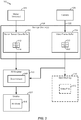
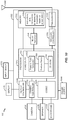
- the system 100 includes a mobile device 102 including a camera 108 configured to capture one or more images (e.g., a first image 120 and a second image 122) of one or more objects, such as an object 130.
- the mobile device 102 further includes one or more motion sensors 104, one or more storage devices 106, and a 3D modeler 110.
- the 3D modeler 110 may be implemented using hardware, using processor-executable instructions stored at a computer-readable tangible medium, or a combination thereof, as described further below.
- the one or more motion sensors 104 may include one or more electrical, mechanical, electromechanical, or other sensors, such as a gyroscope, an accelerometer, other motion sensor devices, or a combination thereof.
- the object 130 may include one or more feature points, such as apexes of the object 130, a base of the object 130, a handle of the object 130, text or graphics on the object 130, curves of the object 130, one or more other distinct portions of the object 130, or any combination thereof.
- PIG. 1 shows two images 120, 122 of the object 130 captured by the camera 108 when the mobile device 102 is at two positions, it should be noted that multiple images of the object 130 corresponding to multiple positions of the mobile device 102 may be captured by the camera 108.
- the camera 108 may be configured to capture images of the object 130 at multiple positions of the mobile device 102 (e.g., at different angles and/or rotations with respect to a coordinate system or with respect to an initial position). For example, the camera 108 may capture a first image 120 of the object 130 when the mobile device 102 (and the camera 108) is at a first position (e.g., a first view 140 of the object 130) and the camera 108 may capture a second image 122 of the object 130 when the mobile device 102 (and the camera 108) is at a second position (e.g., a second view 150 of the object 130).
- image data corresponding to the first view 140 and to the second view 150 may be stored at the one or more storage devices 106.
- the one or more motion sensors 104 may be configured to generate motion sensor data that indicates a position of the mobile device 102 (e.g., rotation and/or translation of the mobile device 102 with respect to an initial position of the mobile device 102 or with respect to a coordinate system).
- the one or more motion sensors 104 may be configured to generate motion sensor data 112 concurrently with the camera 108 capturing the first image 120.
- the one or more motion sensors 104 may be configured to generate motion sensor data 114 concurrently with the camera 108 capturing the second image 122.
- the mobile device 102 uses the 3D modeler 110 to generate a 3D model 116 of the object 130 using the motion sensor data 112, 114 and further using image data related to the images 120, 122, as described further below.
- the mobile device 102 may capture the first image 120 of the object 130 via the camera 108 based on the first view 140 of the camera 108.
- the mobile device 102 may move to a second position (e.g., due to movement of a user of the mobile device 102) and may capture the second image 122 of the object 130 via the camera 108 based on the second view 150 of the camera 108.
- the one or more motion sensors 104 of the mobile device 102 may output motion sensor data 112, 114 corresponding to motion information of the mobile device 102 that enables determination of movement of the mobile device 102 from the first position to the second position.
- the motion sensor data 112, 114 may indicate rotational and translational motion of the mobile device 102.
- the 3D modeler 110 may receive data corresponding to the first image 120 and may further receive the motion sensor data 112 output by the one or more motion sensors 104.
- the 3D modeler 110 may receive the data corresponding to the second image 122 and may further receive the motion sensor data 114 output by the one or more motion sensors 104.
- the motion sensor data 114 may indicate movement information of the mobile device 102 from the first position to the second position.
- the motion sensor data 114 may include rotational and translational matrices of the mobile device 102 associated with rotation and translation of the mobile device 102 from the first position to the second position.
- the motion sensor data 112, 114 may provide information that enables generation of rotational and translational matrices of the mobile device 102.
- the motion sensor data 112, 114 may include or indicate a "camera pose" matrix obtained from the one or more motion sensors 104, as described further below.
- a non-limiting, example operation is provided of the 3D modeler 110 using the motion sensor data 112, 114 and data corresponding to the images 120, 122 to generate the 3D model 116 of the object 130.
- the 3D modeler 110 is configured to generate the 3D model 116 by calculating the bundle adjustment expression min P i , X j ⁇ i , j d P i X j , x j i 2 , based on the motion sensor data 114 provided by the one or more motion sensors 104.
- the 3D modeler 110 may output 3D feature points of the object 130 based on the calculation.
- computing the bundle adjustment expression may include determining feature points of the object 130 based on a function of a first estimated reprojected image point, a second estimated reprojected image point, and the data output by the one or more motion sensors 104.
- computing the bundle adjustment expression may include determining the first estimated reprojected image point of the object 130 based on a product of a first estimate of the first position (i.e., P 1 ) and one or more feature points ( X j ) of the object 130 (i.e., computing P 1 X j ).
- Computing the bundle adjustment expression may also include determining a second estimated reprojected image point of the object based on a product of a second estimate of the second position (i.e., P 2 ) and the one or more feature points ( X j ) of the object 130 (i.e., computing P 2 X j ) , Computing the bundle adjustment expression may also include determining a square of a first Euclidean distance between the first estimated reprojected image point and coordinates of the object 130 in the first image 120 (i.e., computing d P 1 X j , x j 1 2 ) and determining a square of a second Euclidean distance between the second estimated reprojected image point and coordinates of the object 130 in the second image 122 (i.e., computing d P 1 X j , x j 2 2 ).
- Computing the bundle adjustment expression may include modifying an estimate of the 3D model 116 to reduce or to "minimize” a sum of the square of the first Euclidean distance and the square of the second Euclidean distance (i.e., "minimizing" d P 1 X j , x j 1 2 + d P 2 X j , x j 2 2 ).
- the first estimate of the first position P 1 may also be modified to further reduce the sum of the squares.
- ⁇ [ R i
- P 2 ... P n a complexity of generating the feature points may be significantly reduced.
- d ( ⁇ ) may represent a distance function such as a geometric distance or any other metric that measures the distance or difference between the projected feature coordinates and the measured feature coordinates in the images.
- the camera pose information may be determined according to a variety of techniques. To illustrate, suppose at least one of the one or more feature points X j is "matched" (e.g., identified) in N images (e.g., the first image 120 and the second image 122) captured by the camera 108.
- the upper triangular calibration matrix K i K i may be the same for images captured with a same camera (e.g., when the camera 108 is used to capture each of the N images, such as for a single-camera embodiment of the mobile device 102).
- T i ] may be the relative pose matrix associated with the i -th camera.
- a bundle adjustment technique in accordance with the foregoing description may utilize camera pose data (e.g., the motion sensor data 112, 114) to enable simplified and computationally efficient determination of the 3D model 116.
- Conventional approaches e.g., bundle adjustment calculations that do not utilize motion sensor information
- may be subject to a computationally intensive "least squares solution,” such as by obtaining a nonlinear solution to "minimize" geometric error: min X , p i ⁇ i 1 N x i ⁇ p 1 i M p 3 i M 2 + y i ⁇ p 2 i M p 3 i M 2 .
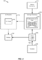
- FIG. 2 depicts a particular illustrative embodiment of the mobile device 102.
- the mobile device 102 of FIG. 2 includes the one or more motion sensors 104, the one or more storage devices 106, the camera 108, and the 3D modeler 110.
- the one or more storage devices 106 store 3D reconstruction data 202 to be used by the 3D modeler 110 to generate the 3D model 116.
- the 3D reconstruction data 202 may include the motion sensor data 112, 114 and may further include first image data 220 and second image data 222 corresponding to the first image 120 of FIG. 1 and to the second image 122 of FIG. 1 , respectively.
- the 3D model 116 may be displayed on a display of the mobile device 102 (not shown in FIG. 2 ).
- the image data 220, 222 of FIG. 2 corresponds to a sequence of pictures, each pictures individually captured in response to user input (e.g., "still” or “snapshot” pictures that are "manually” captured by a user and not part of a video sequence).
- the example of FIG. 2 may be used in connection with an application of the mobile device 102 that enables users to generate 3D models, such as the 3D model 116, based on still pictures captured by users using the camera 108.
- the image data 220, 222 may correspond to video frames of a video frame sequence (e.g., sequential still images that are "automatically” periodically captured).
- FIG. 3 depicts another particular illustrative embodiment of the mobile device 102 described with reference to FIG. 1 .
- the mobile device 102 of FIG. 3 includes the one or more motion sensors 104, the one or more storage devices 106, the camera 108, the 3D modeler 110, and a display 320.
- the 3D modeler 110 of FIG. 3 includes a synchronizer 308.
- the one or more storage devices 106 of FIG. 3 include a motion sensor data buffer 306 and a video frame buffer 304.
- the mobile device 102 of FIG. 3 may include a main memory 310.
- the camera 108 may capture a video frame sequence 302.
- the video frame buffer 304 may be responsive to the camera 108 and configured to store one or more video frames of the video frame sequence 302.
- the image data 220, 222 correspond to video frames of the video frame sequence 302.
- the motion sensor data buffer 306 may be responsive to the one or more motion sensors 104.
- the motion sensor data buffer 306 may store the motion sensor data 112, 114.
- the synchronizer 308 may synchronize data from the video frame buffer 304 with respect to data from the motion sensor data buffer 306. For example, the synchronizer 308 may synchronize the first motion sensor data 112 with the first image data 220 and may further synchronize the second motion sensor data 114 with the second image data 222. According to at least a first technique, the synchronizer 308 synchronizes data from the video frame buffer 304 with respect to data from the motion sensor data buffer 306 by comparing timestamps, such as by comparing timestamps associated with the motion sensor data 112, 114 to timestamps associated with the image data 220, 222.
- the synchronizer 308 periodically accesses data from the motion sensor data buffer 306 and from the video frame buffer 304.
- the synchronizer 308 is responsive to the movement of the mobile device 102 (e.g., is responsive to the one or more motion sensors 104) and pulls data from the motion sensor data buffer 306 and from the video frame buffer 304 in response to the detected motion.
- Further techniques may utilize a combination of one or more of the first technique, the second technique, and the third technique.
- the data output by the video frame buffer 304 may be stored at the main memory 310 as a video file 312 that includes the video frame sequence 302.
- the 3D modeler 110 may operate “on the fly.” For example, the 3D modeler 110 may generate the 3D model 116 and the mobile device 102 may display the 3D model 116 on the display 320 concurrently or substantially concurrently with the video frame sequence 302 being captured.
- “on the fly,” “concurrently,” and “substantially concurrently” refer to a relationship between a view of a captured object and generation of a 3D model of the object that a user may perceive as being simultaneous
- the example illustrated in connection with FIG. 3 may correspond to an "on the fly” generation of the 3D model 116.
- the 3D modeler 110 may "automatically" render the 3D model 116, which is displayed on the display 320 concurrently with the user movement.
- one or more embodiments may enable non-concurrent generation of 3D models based on motion sensor data and a video frame sequence.
- FIG. 4 depicts another particular illustrative embodiment of the mobile device 102 described with reference to FIG. 1 .
- the mobile device 102 of FIG. 4 includes the one or more motion sensors 104, the one or more storage devices 106, the camera 108, the 3D modeler 110, the video frame buffer 304, and the display 320.
- the one or more motion sensors 104 may generate the motion sensor data 112, 114, which may be stored at the one or more storage devices 106.
- the camera 108 may capture the video frame sequence 302, which may be stored temporarily at the video frame buffer 304 and displayed at the display 320, such as in connection with a "preview" feature associated with the video frame sequence 302.
- the video frame sequence 302 may be displayed at the display 320 prior to the video frame sequence 302 being stored at the one or more storage devices 106 (e.g., as the image data 220, 222) and/or prior to the 3D modeler 110 generating the 3D model 116.
- the 3D modeler 110 may generate the 3D model 116 according to a "post-processing" technique.
- the display 320 can instead show a "preview" of the images being captured by the camera 108.
- the display 320 may display user instructions for camera positioning (e.g., angles and/or positions at which the camera is to be held with respect to object being viewed).
- the 3D model 116 can thereafter be generated by the 3D modeler 110 by accessing the one or more storage devices 106, which may be a "main memory,” such as the main memory 310 described in connection with FIG. 3 .
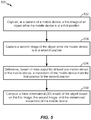
- the method 500 includes capturing, at a camera of a mobile device, a first image of an object while the mobile device is at a first position, at 502, and capturing a second image of the object while the mobile device is at a second position, at 504.
- the camera 108 may capture the first image 120 of the object 130 while the mobile device 102 is at the first position any the camera 108 may capture the second image 122 of the object 130 while the mobile device 102 is at the second position.
- the first image 120 may correspond to the first view 140 of the object 130 as captured by the camera 108 while at the first position and the second image 122 may correspond, to the second view 150 of the object 130 as captured by the camera 108 while at the second position.
- the method 500 further includes determining, based on data output by at least one motion sensor of the mobile device, a movement of the mobile device from the first position to the second position, at 506.
- the one or more motion sensors 104 may output motion sensor data 112, 114 corresponding to motion information of the mobile device 102.
- the motion information may include rotation and translation of the mobile device 102 from the first position to the second position.
- the one or more motion sensors may provide first rotational and/or translational matrices of the mobile device 102 corresponding to the first position and second rotational and/or translational matrices of the mobile device 102 corresponding to the second position.
- the first position of the mobile device is used as a "preference" position, and the second position accordingly indicates a change in position of the mobile device.
- another position e.g., a previous position, or a position associated with a predetermined coordinate system
- both the first position and the second position each indicate a change in position of the mobile device.
- the method 500 also includes computing a 3D model of the object based on the first image, the second image, and the determined movement of the mobile device, at 508.
- the 3D modeler 110 may compute feature points of the object 130 based on the first image 120 and the second image 122.
- the 3D modeler 110 may be configured to calculate the bundle adjustment expression min P i , X j ⁇ i , j d P i X j , x j i 2 based on the motion sensor data 114 provided by the one or more motion sensors 104, the first image 120, and the second image 122.
- the 3D model may be computed according to a silhouette-based technique (e.g., a visual hull technique).
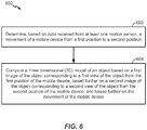
- a diagram illustrating another particular embodiment of a method of computing a three-dimensional (3D) model based on motion sensor data is disclosed and generally designated 600.
- the method 600 includes determining, based on data received from at least one motion sensor, a movement of a mobile device from a first position to a second position, at 602.
- the data, the at least one motion sensor, and the mobile device may correspond to the motion sensor data 112, 114, the one or more motion sensors 104, and the mobile device 102, respectively.
- the method 600 further includes computing a 3D model of an object based on a first image of the object corresponding to a first view of the object from the first position of the mobile device, based further on a second image of the object corresponding to a second view of the object from the second position of the mobile device, and based further on the movement of the mobile device, at 604.
- the camera 108 may capture the first image 120 of the object 130 while the mobile device 102 is at the first position and the camera 108 may capture the second image 122 of the object 130 while the mobile device 102 is at the second position.
- the first image 120 may correspond to the first view 140 of the object 130 as captured by the camera 108 while at the first position and the second image 122 may correspond to the second view 150 of the object 130 as captured by the camera 108 while at the second position.
- a flow diagram illustrating a particular embodiment of a method of computing a 3D model according to a feature point-based reconstruction technique (e.g., a bundle adjustment technique) based on motion sensor data is depicted and generally designated 700.
- the method 700 includes capturing images (e.g., the images 120, 122) of an object (e.g., the object 130) using a camera (e.g., the camera 108) of a mobile device (e.g., the mobile device 102), at 702.
- the method 700 includes determining motion sensor data (e.g., the motion sensor data 112, 114) using one or more motion sensors (e.g., the one or more motion sensors 104).
- one or more feature points of the images are matched, and at 708, a 3D location for each of the one or more matched features is determined. Determining the one or more feature points and the 3D locations for each of the one or more matched feature points can be performed using any suitable technique, such as the bundle adjustment technique described above with reference to at least FIG. 1 .
- a 3D model of the object is generated using the one or more matched features (e.g., according to the bundle adjustment technique).
- the method 700 of FIG. 7 is performed using a processor of the mobile device 102, as described further with reference to at least FIG. 10 .
- FIG. 8 a flow diagram illustrating a particular embodiment of a method of computing a 3D model according to a silhouette-based reconstruction technique (e.g., a visual hull technique) based on motion sensor data is depicted and generally designated 800.
- the method 800 includes capturing images (e.g., the images 120, 122) of an object (e.g., the object 130) using a camera (e.g., the camera 108) of a mobile device (e.g., the mobile device 102), at 802.
- motion sensor data (e.g., the motion sensor data 112, 114) is determined using one or more motion sensors (e.g., the one or more motion sensors 104) of the mobile device.
- a silhouette is generated of the object in each of the images, at 806.
- the method 800 further includes generating a silhouette-based model of the object, at 808, and generating a 3D model based on the silhouette-based model, at 810.
- a particular example of a silhouette-based reconstruction technique is described with reference to FIG 9 .
- FIG. 9 a flow diagram illustrating another particular embodiment, of a method of computing a 3D model according to a silhouette-based reconstruction technique (e.g., a visual hull technique) based on motion sensor data is depicted and generally designated 900.
- the method 900 includes scanning by a mobile device (e.g., the mobile device 102) each pixel of a first view and projecting a ray R based on a view direction, at 902.
- the ray R is projected to one or more reference images and an interval I is found such that the internal I intersects a silhouette of each of the images.
- motion sensor data (e.g., the motion sensor data 112, 114) indicating a change in position of the mobile device (e.g., from a first position to a second position) is determined via at least one sensor (e.g., via the one or more motion sensors 104).
- the motion sensor data determined at 906 is used to project the ray R to the one or more reference images, at 902.
- the method 900 further includes projecting the interval I back into 3D space using a known camera projection P i as a 3D interval L , at 908.
- the known camera projection P i may be derived from the motion sensor data.
- the method 900 further includes selecting an innermost (e.g., shortest) intersection Q from the overlapping L s, where Q is a final 3D interval having end points corresponding to surface points of a 3D model to be constructed, at 910.
- Q is a final 3D interval having end points corresponding to surface points of a 3D model to be constructed
- another ray or view is added, at 914.
- the 3D model e.g., the 3D model 116) is generated using the intersections Q s.
- the method 800 of FIG. 8 , the method 900 of FIG. 9 , or a combination thereof, may be performed using a processor of the mobile device 102, as described further with reference to at least FIG. 11 .
- FIG. 10 is a diagram of another particular illustrative embodiment of the mobile device 102, where the mobile device 102 is configured to compute 3D models according to a feature point-based reconstruction technique (e.g., a bundle adjustment technique) based on motion sensor data.
- the mobile device 102 of FIG. 10 includes a processor, such as a processor 1010, coupled to a memory 1032, and to the one or more motion sensors 104.
- the one or more motion sensors 104 may also be coupled to the memory 1032.
- the memory 1032 may be a computer-readable non-transitory medium that stores data (e.g., motion data of the mobile device 102), instructions, or a combination thereof.
- the memory 1032 may include instructions 1054 that may be executable by the processor 1010 to cause the processor 1010 to perform one or more functions of the mobile device 102.
- the instructions 1054 may include user applications, an operating system, or other executable instructions, or a combination thereof.
- the instructions 1054 may be executable by the processor 1010 to cause the processor 1010 to perform one or more operations described herein, such as to determined movement of the mobile device 102 based on motion sensor data (e.g., the motion sensor data 112, 114) determined by the one or more motion sensors 104.
- motion sensor data e.g., the motion sensor data 112, 114
- the memory 1032 is a "main memory,” such as the main memory 310 described with reference to FIG. 3 .
- the memory 1032 may include the one or more storage devices 106, the motion sensor data buffer 306, the video frame buffer 304, or a combination thereof.
- the processor 1010 may include the 3D modeler 110.
- the 3D modeler 110 may be a hardware component of the processor 1010, a set of instructions (e.g., instructions stored at the memory 1032) executable by the processor 1010, or a combination thereof.
- the 3D modeler 110 includes a feature point generator 1092, which may determine feature points 1094 of captured images (e.g., the first image 120 and the second image 122 of FIG. 1 ) of an object in connection with a feature-point based reconstruction technique.
- the 3D modeler 110 may generate the 3D model 116 based on the feature points 1094.
- FIG. 10 illustrates the camera 108 coupled to a camera controller 1090 that may provide the images 120, 122 and/or video data to be processed by the 3D modeler 110.
- the camera controller 1090 may be coupled to the processor 1010 and to a display controller 1026.
- the camera 108 may be a video camera, a non-video camera, a single camera, a multi-camera (e.g., a stereo camera), or a combination thereof.
- FIG. 10 also shows that the display controller 1026 may be coupled to the processor 1010 and to the display 320.
- a coder/decoder (CODEC) 1034 (e.g., an audio and/or voice CODEC) may be coupled to the processor 1010.
- a speaker 1036 and a microphone 1038 may be coupled to the CODEC 1034.
- a wireless controller 1040 may be coupled to the processor 1010 and to a transceiver 1050 that is coupled to a wireless antenna 1042,
- the processor 1010, the one or more motion sensors 104, the camera controller 1090, the display controller 1026, the memory 1032, the CODEC 1034, the wireless controller 1040, and the transceiver 1050 are included in a system-in-package or system-on-chip device 1022.
- an input device 1030 and a power supply 1044 are coupled to the system-on-chip device 1022.
- the display 320, the camera 108, the input device 1030, the speaker 1036, the microphone 1038, the wireless antenna 1042, and the power supply 1044 are external to the system-on-chip device 1022.
- each of the display 320, the input device 1030, the speaker 1036, the microphone 1038, the wireless antenna 1042, and the power supply 1044 can be coupled to a component of the system-on-chip device 1022, such as an interface or a controller.
- the one or more motion sensors 104 are illustrated as included in the system-on-chip device 1022, in other embodiments the one or more motion sensors 104 may be external to the system-on-chip device 1022 and coupled to the system-on-chip device 1022.
- FIG. 11 is a diagram of another particular illustrative embodiment of the mobile device 102, where the mobile device 102 is configured to compute 3D models according to a silhouette-based reconstruction technique (e.g., a visual hull technique) based on motion sensor data.
- a silhouette-based reconstruction technique e.g., a visual hull technique
- the 3D modeler 110 of FIG. 11 includes a silhouette generator 1192 to generate a silhouette 1194, for example in connection with a visual hull technique.
- the silhouette 1194 may be used by the 3D modeler 110 to generate the 3D model 116.
- the processor 1010 and the memory 1032 of FIGS. 10 and 11 may be integrated into a multimedia player, an entertainment unit, a navigation device, a personal digital assistant (PDA), a fixed location data unit, or a computer (e.g., a tablet computer, a laptop computer, a desktop computer, etc), a media device, another device configured to wirelessly communicate data, or a combination thereof.
- a multimedia player e.g., an entertainment unit, a navigation device, a personal digital assistant (PDA), a fixed location data unit, or a computer (e.g., a tablet computer, a laptop computer, a desktop computer, etc), a media device, another device configured to wirelessly communicate data, or a combination thereof.
- PDA personal digital assistant
- a media device e.g., a tablet computer, a laptop computer, a desktop computer, etc
- various techniques e.g., reconstruction techniques, such as feature point-based and silhouette-based reconstruction techniques
- one or more such techniques can be combined.
- an apparatus in conjunction with the described embodiments, includes means for determining, based on data received from at least one means for sensing motion, a movement of a mobile device from a first position to a second position.
- the means for determining may include the 3D modeler 110 of FIGS. 1-4 , 10 , and 11 , the processor 1010 of FIGS. 10 and 11 , one or more other devices configured to determine a movement of a mobile device, or any combination thereof.
- the means for sensing motion may include the one or more motion sensors 104.
- the apparatus further includes means for computing a three-dimensional (3D) model of an object based on a first image of the object corresponding to a first view of the object from the first position of the mobile device, based further on a second image of the object corresponding to a second view of the object from the second position of the mobile device, and based further on movement of the mobile device.
- the means for computing the 3D model may include the 3D modeler 110 of FIGS. 1-4 , 10 , and 11 , the processor 1010 of FIGS. 10 and 11 , one or more other devices configured to compute a 3D model, or any combination thereof,
- a software module may reside in random access memory (RAM), flash memory, read-only memory (ROM), programmable read-only memory (PROM), erasable programmable read-only memory (EPROM), electrically erasable programmable read-only memory (EEPROM), registers, hard disk, a removable disk, a compact disc read-only memory (CD-ROM), or any other form of non-transitory storage medium.
- RAM random access memory
- ROM read-only memory
- PROM programmable read-only memory
- EPROM erasable programmable read-only memory
- EEPROM electrically erasable programmable read-only memory
- registers hard disk, a removable disk, a compact disc read-only memory (CD-ROM), or any other form of non-transitory storage medium.
- An exemplary storage medium is coupled to the processor such that the processor can read information from, and write information to, the storage medium. In the alternative, the storage medium may be integral to the processor.
- the processor and the storage medium may reside in an application-specific integrated circuit (ASIC).
- ASIC application-specific integrated circuit
- the ASIC may reside in a computing device or a user terminal (e.g., a mobile phone or a PDA).
- the processor and the storage medium may reside as discrete components in a computing device or user terminal.
Landscapes
- Engineering & Computer Science (AREA)
- Computer Vision & Pattern Recognition (AREA)
- Physics & Mathematics (AREA)
- General Physics & Mathematics (AREA)
- Theoretical Computer Science (AREA)
- Multimedia (AREA)
- Signal Processing (AREA)
- Length Measuring Devices By Optical Means (AREA)
- Image Analysis (AREA)
Applications Claiming Priority (3)
| Application Number | Priority Date | Filing Date | Title |
|---|---|---|---|
| US201261591196P | 2012-01-26 | 2012-01-26 | |
| US13/673,681 US9639959B2 (en) | 2012-01-26 | 2012-11-09 | Mobile device configured to compute 3D models based on motion sensor data |
| PCT/US2012/069088 WO2013112237A1 (en) | 2012-01-26 | 2012-12-12 | Mobile device configured to compute 3d models based on motion sensor data |
Publications (2)
| Publication Number | Publication Date |
|---|---|
| EP2807629A1 EP2807629A1 (en) | 2014-12-03 |
| EP2807629B1 true EP2807629B1 (en) | 2017-09-20 |
Family
ID=48869873
Family Applications (1)
| Application Number | Title | Priority Date | Filing Date |
|---|---|---|---|
| EP12806819.4A Active EP2807629B1 (en) | 2012-01-26 | 2012-12-12 | Mobile device configured to compute 3d models based on motion sensor data |
Country Status (6)
| Country | Link |
|---|---|
| US (1) | US9639959B2 (enExample) |
| EP (1) | EP2807629B1 (enExample) |
| JP (1) | JP6199313B2 (enExample) |
| KR (1) | KR101827046B1 (enExample) |
| CN (1) | CN104081434B (enExample) |
| WO (1) | WO2013112237A1 (enExample) |
Families Citing this family (24)
| Publication number | Priority date | Publication date | Assignee | Title |
|---|---|---|---|---|
| US10261408B2 (en) * | 2010-07-18 | 2019-04-16 | Spatial Cam Llc | Mobile and portable camera platform for tracking an object |
| US9131118B2 (en) * | 2012-11-14 | 2015-09-08 | Massachusetts Institute Of Technology | Laser speckle photography for surface tampering detection |
| CN104813230A (zh) * | 2012-11-30 | 2015-07-29 | 汤姆逊许可公司 | 使用单个相机捕捉三维图像的方法和系统 |
| KR102153539B1 (ko) * | 2013-09-05 | 2020-09-08 | 한국전자통신연구원 | 영상 처리 장치 및 방법 |
| US9173066B1 (en) * | 2014-06-13 | 2015-10-27 | Xerox Corporation | Methods and systems for controlling an electronic device |
| CN104282041A (zh) * | 2014-09-30 | 2015-01-14 | 小米科技有限责任公司 | 三维建模方法及装置 |
| JP6306996B2 (ja) * | 2014-10-01 | 2018-04-04 | 日本電信電話株式会社 | 映像データ処理方法、映像データ処理装置及び映像データ処理プログラム |
| JP2016070891A (ja) * | 2014-10-01 | 2016-05-09 | 日本電信電話株式会社 | 映像データ処理装置及び映像データ処理プログラム |
| KR102248404B1 (ko) | 2014-11-17 | 2021-05-07 | 삼성전자주식회사 | 움직임 분석 방법 및 움직임 분석 장치 |
| CN104517316B (zh) * | 2014-12-31 | 2018-10-16 | 中科创达软件股份有限公司 | 一种三维物体建模方法及终端设备 |
| WO2016141208A1 (en) * | 2015-03-04 | 2016-09-09 | Usens, Inc. | System and method for immersive and interactive multimedia generation |
| CN104794723A (zh) * | 2015-05-04 | 2015-07-22 | 福建师范大学 | 一种基于概率的遥感影像建筑物位置检测方法 |
| US10012509B2 (en) * | 2015-11-12 | 2018-07-03 | Blackberry Limited | Utilizing camera to assist with indoor pedestrian navigation |
| US10341633B2 (en) | 2015-11-20 | 2019-07-02 | Qualcomm Incorporated | Systems and methods for correcting erroneous depth information |
| KR20170076471A (ko) | 2015-12-24 | 2017-07-04 | 삼성전자주식회사 | 변형 가능한 디스플레이 장치 및 이를 이용한 영상 표시 방법 |
| US11345053B2 (en) | 2016-09-16 | 2022-05-31 | Verb Surgical Inc. | Belt termination and tensioning in a pulley arrangement for a robotic arm |
| US10841486B2 (en) * | 2017-07-20 | 2020-11-17 | Eclo, Inc. | Augmented reality for three-dimensional model reconstruction |
| CN108235764B (zh) * | 2017-12-29 | 2022-09-16 | 达闼机器人股份有限公司 | 信息处理方法、装置、云处理设备及计算机程序产品 |
| JP6970817B2 (ja) * | 2018-04-11 | 2021-11-24 | 富士フイルム株式会社 | 構造物管理装置、構造物管理方法、及び構造物管理プログラム |
| CN113140030B (zh) * | 2020-01-17 | 2024-12-31 | 北京小米移动软件有限公司 | 三维模型生成方法、装置及存储介质 |
| US20210259779A1 (en) * | 2020-02-20 | 2021-08-26 | Verb Surgical Inc. | Multi-camera user interface device calibration and tracking |
| US11694313B2 (en) * | 2020-02-28 | 2023-07-04 | Unity Technologies Sf | Computer-generated image processing including volumetric scene reconstruction |
| FR3122763B1 (fr) * | 2021-05-07 | 2024-07-26 | Captana Gmbh | Procédé automatisé de réglage d’un paramètre de visualisation d’un dispositif d’imagerie en magasin |
| CN117795972A (zh) | 2021-08-04 | 2024-03-29 | 三星电子株式会社 | 用于视频序列的帧稳定的方法和电子设备 |
Citations (1)
| Publication number | Priority date | Publication date | Assignee | Title |
|---|---|---|---|---|
| WO2011144408A1 (fr) * | 2010-05-17 | 2011-11-24 | Commissariat A L'energie Atomique Et Aux Energies Alternatives | Procede et systeme pour fusionner des donnees issues de capteurs d'images et de capteurs de mouvement ou de position |
Family Cites Families (23)
| Publication number | Priority date | Publication date | Assignee | Title |
|---|---|---|---|---|
| US6094215A (en) | 1998-01-06 | 2000-07-25 | Intel Corporation | Method of determining relative camera orientation position to create 3-D visual images |
| AU4690899A (en) * | 1998-06-18 | 2000-01-05 | Kline & Walker Llc | Automated devices to control equipment and machines with remote control and accountability worldwide |
| US7466843B2 (en) * | 2000-07-07 | 2008-12-16 | Pryor Timothy R | Multi-functional control and entertainment systems |
| US6539330B2 (en) | 2000-07-19 | 2003-03-25 | Pentax Corporation | Method and apparatus for measuring 3-D information |
| US6961055B2 (en) * | 2001-05-09 | 2005-11-01 | Free Radical Design Limited | Methods and apparatus for constructing virtual environments |
| JP2003006680A (ja) | 2001-06-20 | 2003-01-10 | Zenrin Co Ltd | 3次元電子地図データの生成方法 |
| EP1625488A2 (en) * | 2003-05-20 | 2006-02-15 | Lego A/S | Method and system for manipulating a digital representation of a three-dimensional object |
| US7596473B2 (en) * | 2003-05-20 | 2009-09-29 | Interlego Ag | Method of constructing a virtual construction model |
| JP4132068B2 (ja) | 2005-02-28 | 2008-08-13 | 学校法人早稲田大学 | 画像処理装置及び三次元計測装置並びに画像処理装置用プログラム |
| JP4910312B2 (ja) * | 2005-06-03 | 2012-04-04 | ソニー株式会社 | 撮像装置および撮像方法 |
| US7856125B2 (en) | 2006-01-31 | 2010-12-21 | University Of Southern California | 3D face reconstruction from 2D images |
| CN101395613A (zh) | 2006-01-31 | 2009-03-25 | 南加利福尼亚大学 | 由2d图像实现3d人脸重建 |
| US20070248260A1 (en) | 2006-04-20 | 2007-10-25 | Nokia Corporation | Supporting a 3D presentation |
| US8498497B2 (en) | 2006-11-17 | 2013-07-30 | Microsoft Corporation | Swarm imaging |
| US7676146B2 (en) * | 2007-03-09 | 2010-03-09 | Eastman Kodak Company | Camera using multiple lenses and image sensors to provide improved focusing capability |
| JP2009200713A (ja) | 2008-02-20 | 2009-09-03 | Sony Corp | 画像処理装置、画像処理方法、プログラム |
| US8625846B2 (en) * | 2008-03-18 | 2014-01-07 | Elliptic Laboratories As | Object and movement detection |
| US20100316282A1 (en) | 2009-06-16 | 2010-12-16 | Hope Clinton B | Derivation of 3D information from single camera and movement sensors |
| WO2011091552A1 (en) | 2010-02-01 | 2011-08-04 | Intel Corporation | Extracting and mapping three dimensional features from geo-referenced images |
| US20110234750A1 (en) | 2010-03-24 | 2011-09-29 | Jimmy Kwok Lap Lai | Capturing Two or More Images to Form a Panoramic Image |
| KR20110116525A (ko) | 2010-04-19 | 2011-10-26 | 엘지전자 주식회사 | 3d 오브젝트를 제공하는 영상표시장치, 그 시스템 및 그 동작 제어방법 |
| US8918209B2 (en) | 2010-05-20 | 2014-12-23 | Irobot Corporation | Mobile human interface robot |
| JP2015507860A (ja) * | 2011-12-07 | 2015-03-12 | インテル コーポレイション | 画像キャプチャのガイド |
-
2012
- 2012-11-09 US US13/673,681 patent/US9639959B2/en active Active
- 2012-12-12 WO PCT/US2012/069088 patent/WO2013112237A1/en not_active Ceased
- 2012-12-12 CN CN201280066984.2A patent/CN104081434B/zh active Active
- 2012-12-12 JP JP2014554717A patent/JP6199313B2/ja active Active
- 2012-12-12 EP EP12806819.4A patent/EP2807629B1/en active Active
- 2012-12-12 KR KR1020147019346A patent/KR101827046B1/ko active Active
Patent Citations (1)
| Publication number | Priority date | Publication date | Assignee | Title |
|---|---|---|---|---|
| WO2011144408A1 (fr) * | 2010-05-17 | 2011-11-24 | Commissariat A L'energie Atomique Et Aux Energies Alternatives | Procede et systeme pour fusionner des donnees issues de capteurs d'images et de capteurs de mouvement ou de position |
Also Published As
| Publication number | Publication date |
|---|---|
| WO2013112237A1 (en) | 2013-08-01 |
| US20130194392A1 (en) | 2013-08-01 |
| EP2807629A1 (en) | 2014-12-03 |
| CN104081434B (zh) | 2018-01-05 |
| KR20140116867A (ko) | 2014-10-06 |
| CN104081434A (zh) | 2014-10-01 |
| JP6199313B2 (ja) | 2017-09-20 |
| US9639959B2 (en) | 2017-05-02 |
| JP2015508197A (ja) | 2015-03-16 |
| KR101827046B1 (ko) | 2018-02-07 |
Similar Documents
| Publication | Publication Date | Title |
|---|---|---|
| EP2807629B1 (en) | Mobile device configured to compute 3d models based on motion sensor data | |
| US12387431B2 (en) | 3D model reconstruction and scale estimation | |
| US20220351473A1 (en) | Mobile augmented reality system | |
| JP7223449B2 (ja) | 撮影に基づく3dモデリングシステム | |
| US11380078B2 (en) | 3-D reconstruction using augmented reality frameworks | |
| CN110462686B (zh) | 用于从场景获得深度信息的设备和方法 | |
| CN106062821B (zh) | 用于不受限制的slam的基于传感器的相机运动检测 | |
| US8675049B2 (en) | Navigation model to render centered objects using images | |
| JP2015508197A5 (enExample) | ||
| JP2016502720A (ja) | 場面の3d再構築および3dパノラマモザイキングの方法 | |
| CN105705903A (zh) | 3维形状计测装置、3维形状计测方法及3维形状计测程序 | |
| US8509522B2 (en) | Camera translation using rotation from device | |
| TWI502271B (zh) | 控制方法及電子裝置 | |
| CA3102860C (en) | Photography-based 3d modeling system and method, and automatic 3d modeling apparatus and method | |
| Manabe et al. | Three-Dimensional Map Generating System by a Walk |
Legal Events
| Date | Code | Title | Description |
|---|---|---|---|
| PUAI | Public reference made under article 153(3) epc to a published international application that has entered the european phase |
Free format text: ORIGINAL CODE: 0009012 |
|
| 17P | Request for examination filed |
Effective date: 20140701 |
|
| AK | Designated contracting states |
Kind code of ref document: A1 Designated state(s): AL AT BE BG CH CY CZ DE DK EE ES FI FR GB GR HR HU IE IS IT LI LT LU LV MC MK MT NL NO PL PT RO RS SE SI SK SM TR |
|
| DAX | Request for extension of the european patent (deleted) | ||
| 17Q | First examination report despatched |
Effective date: 20151207 |
|
| REG | Reference to a national code |
Ref country code: DE Ref legal event code: R079 Ref document number: 602012037631 Country of ref document: DE Free format text: PREVIOUS MAIN CLASS: G06T0007000000 Ipc: G06T0007564000 |
|
| GRAP | Despatch of communication of intention to grant a patent |
Free format text: ORIGINAL CODE: EPIDOSNIGR1 |
|
| RIC1 | Information provided on ipc code assigned before grant |
Ipc: G06T 7/579 20170101ALI20170307BHEP Ipc: G06T 7/564 20170101AFI20170307BHEP |
|
| INTG | Intention to grant announced |
Effective date: 20170329 |
|
| GRAS | Grant fee paid |
Free format text: ORIGINAL CODE: EPIDOSNIGR3 |
|
| GRAA | (expected) grant |
Free format text: ORIGINAL CODE: 0009210 |
|
| AK | Designated contracting states |
Kind code of ref document: B1 Designated state(s): AL AT BE BG CH CY CZ DE DK EE ES FI FR GB GR HR HU IE IS IT LI LT LU LV MC MK MT NL NO PL PT RO RS SE SI SK SM TR |
|
| REG | Reference to a national code |
Ref country code: GB Ref legal event code: FG4D |
|
| REG | Reference to a national code |
Ref country code: CH Ref legal event code: EP |
|
| REG | Reference to a national code |
Ref country code: AT Ref legal event code: REF Ref document number: 930704 Country of ref document: AT Kind code of ref document: T Effective date: 20171015 |
|
| REG | Reference to a national code |
Ref country code: IE Ref legal event code: FG4D |
|
| REG | Reference to a national code |
Ref country code: DE Ref legal event code: R096 Ref document number: 602012037631 Country of ref document: DE |
|
| REG | Reference to a national code |
Ref country code: FR Ref legal event code: PLFP Year of fee payment: 6 |
|
| REG | Reference to a national code |
Ref country code: NL Ref legal event code: MP Effective date: 20170920 |
|
| PG25 | Lapsed in a contracting state [announced via postgrant information from national office to epo] |
Ref country code: NO Free format text: LAPSE BECAUSE OF FAILURE TO SUBMIT A TRANSLATION OF THE DESCRIPTION OR TO PAY THE FEE WITHIN THE PRESCRIBED TIME-LIMIT Effective date: 20171220 Ref country code: SE Free format text: LAPSE BECAUSE OF FAILURE TO SUBMIT A TRANSLATION OF THE DESCRIPTION OR TO PAY THE FEE WITHIN THE PRESCRIBED TIME-LIMIT Effective date: 20170920 Ref country code: HR Free format text: LAPSE BECAUSE OF FAILURE TO SUBMIT A TRANSLATION OF THE DESCRIPTION OR TO PAY THE FEE WITHIN THE PRESCRIBED TIME-LIMIT Effective date: 20170920 Ref country code: FI Free format text: LAPSE BECAUSE OF FAILURE TO SUBMIT A TRANSLATION OF THE DESCRIPTION OR TO PAY THE FEE WITHIN THE PRESCRIBED TIME-LIMIT Effective date: 20170920 Ref country code: LT Free format text: LAPSE BECAUSE OF FAILURE TO SUBMIT A TRANSLATION OF THE DESCRIPTION OR TO PAY THE FEE WITHIN THE PRESCRIBED TIME-LIMIT Effective date: 20170920 |
|
| REG | Reference to a national code |
Ref country code: LT Ref legal event code: MG4D |
|
| REG | Reference to a national code |
Ref country code: AT Ref legal event code: MK05 Ref document number: 930704 Country of ref document: AT Kind code of ref document: T Effective date: 20170920 |
|
| PG25 | Lapsed in a contracting state [announced via postgrant information from national office to epo] |
Ref country code: BG Free format text: LAPSE BECAUSE OF FAILURE TO SUBMIT A TRANSLATION OF THE DESCRIPTION OR TO PAY THE FEE WITHIN THE PRESCRIBED TIME-LIMIT Effective date: 20171220 Ref country code: GR Free format text: LAPSE BECAUSE OF FAILURE TO SUBMIT A TRANSLATION OF THE DESCRIPTION OR TO PAY THE FEE WITHIN THE PRESCRIBED TIME-LIMIT Effective date: 20171221 Ref country code: RS Free format text: LAPSE BECAUSE OF FAILURE TO SUBMIT A TRANSLATION OF THE DESCRIPTION OR TO PAY THE FEE WITHIN THE PRESCRIBED TIME-LIMIT Effective date: 20170920 Ref country code: LV Free format text: LAPSE BECAUSE OF FAILURE TO SUBMIT A TRANSLATION OF THE DESCRIPTION OR TO PAY THE FEE WITHIN THE PRESCRIBED TIME-LIMIT Effective date: 20170920 |
|
| PG25 | Lapsed in a contracting state [announced via postgrant information from national office to epo] |
Ref country code: NL Free format text: LAPSE BECAUSE OF FAILURE TO SUBMIT A TRANSLATION OF THE DESCRIPTION OR TO PAY THE FEE WITHIN THE PRESCRIBED TIME-LIMIT Effective date: 20170920 |
|
| PG25 | Lapsed in a contracting state [announced via postgrant information from national office to epo] |
Ref country code: ES Free format text: LAPSE BECAUSE OF FAILURE TO SUBMIT A TRANSLATION OF THE DESCRIPTION OR TO PAY THE FEE WITHIN THE PRESCRIBED TIME-LIMIT Effective date: 20170920 Ref country code: CZ Free format text: LAPSE BECAUSE OF FAILURE TO SUBMIT A TRANSLATION OF THE DESCRIPTION OR TO PAY THE FEE WITHIN THE PRESCRIBED TIME-LIMIT Effective date: 20170920 Ref country code: RO Free format text: LAPSE BECAUSE OF FAILURE TO SUBMIT A TRANSLATION OF THE DESCRIPTION OR TO PAY THE FEE WITHIN THE PRESCRIBED TIME-LIMIT Effective date: 20170920 Ref country code: PL Free format text: LAPSE BECAUSE OF FAILURE TO SUBMIT A TRANSLATION OF THE DESCRIPTION OR TO PAY THE FEE WITHIN THE PRESCRIBED TIME-LIMIT Effective date: 20170920 |
|
| PG25 | Lapsed in a contracting state [announced via postgrant information from national office to epo] |
Ref country code: SM Free format text: LAPSE BECAUSE OF FAILURE TO SUBMIT A TRANSLATION OF THE DESCRIPTION OR TO PAY THE FEE WITHIN THE PRESCRIBED TIME-LIMIT Effective date: 20170920 Ref country code: AT Free format text: LAPSE BECAUSE OF FAILURE TO SUBMIT A TRANSLATION OF THE DESCRIPTION OR TO PAY THE FEE WITHIN THE PRESCRIBED TIME-LIMIT Effective date: 20170920 Ref country code: EE Free format text: LAPSE BECAUSE OF FAILURE TO SUBMIT A TRANSLATION OF THE DESCRIPTION OR TO PAY THE FEE WITHIN THE PRESCRIBED TIME-LIMIT Effective date: 20170920 Ref country code: SK Free format text: LAPSE BECAUSE OF FAILURE TO SUBMIT A TRANSLATION OF THE DESCRIPTION OR TO PAY THE FEE WITHIN THE PRESCRIBED TIME-LIMIT Effective date: 20170920 Ref country code: IS Free format text: LAPSE BECAUSE OF FAILURE TO SUBMIT A TRANSLATION OF THE DESCRIPTION OR TO PAY THE FEE WITHIN THE PRESCRIBED TIME-LIMIT Effective date: 20180120 Ref country code: IT Free format text: LAPSE BECAUSE OF FAILURE TO SUBMIT A TRANSLATION OF THE DESCRIPTION OR TO PAY THE FEE WITHIN THE PRESCRIBED TIME-LIMIT Effective date: 20170920 |
|
| REG | Reference to a national code |
Ref country code: DE Ref legal event code: R097 Ref document number: 602012037631 Country of ref document: DE |
|
| PLBE | No opposition filed within time limit |
Free format text: ORIGINAL CODE: 0009261 |
|
| STAA | Information on the status of an ep patent application or granted ep patent |
Free format text: STATUS: NO OPPOSITION FILED WITHIN TIME LIMIT |
|
| PG25 | Lapsed in a contracting state [announced via postgrant information from national office to epo] |
Ref country code: DK Free format text: LAPSE BECAUSE OF FAILURE TO SUBMIT A TRANSLATION OF THE DESCRIPTION OR TO PAY THE FEE WITHIN THE PRESCRIBED TIME-LIMIT Effective date: 20170920 |
|
| REG | Reference to a national code |
Ref country code: CH Ref legal event code: PL |
|
| 26N | No opposition filed |
Effective date: 20180621 |
|
| REG | Reference to a national code |
Ref country code: IE Ref legal event code: MM4A |
|
| PG25 | Lapsed in a contracting state [announced via postgrant information from national office to epo] |
Ref country code: MT Free format text: LAPSE BECAUSE OF NON-PAYMENT OF DUE FEES Effective date: 20171212 Ref country code: LU Free format text: LAPSE BECAUSE OF NON-PAYMENT OF DUE FEES Effective date: 20171212 |
|
| REG | Reference to a national code |
Ref country code: BE Ref legal event code: MM Effective date: 20171231 |
|
| PG25 | Lapsed in a contracting state [announced via postgrant information from national office to epo] |
Ref country code: IE Free format text: LAPSE BECAUSE OF NON-PAYMENT OF DUE FEES Effective date: 20171212 |
|
| PG25 | Lapsed in a contracting state [announced via postgrant information from national office to epo] |
Ref country code: LI Free format text: LAPSE BECAUSE OF NON-PAYMENT OF DUE FEES Effective date: 20171231 Ref country code: BE Free format text: LAPSE BECAUSE OF NON-PAYMENT OF DUE FEES Effective date: 20171231 Ref country code: CH Free format text: LAPSE BECAUSE OF NON-PAYMENT OF DUE FEES Effective date: 20171231 Ref country code: SI Free format text: LAPSE BECAUSE OF FAILURE TO SUBMIT A TRANSLATION OF THE DESCRIPTION OR TO PAY THE FEE WITHIN THE PRESCRIBED TIME-LIMIT Effective date: 20170920 |
|
| PG25 | Lapsed in a contracting state [announced via postgrant information from national office to epo] |
Ref country code: MC Free format text: LAPSE BECAUSE OF FAILURE TO SUBMIT A TRANSLATION OF THE DESCRIPTION OR TO PAY THE FEE WITHIN THE PRESCRIBED TIME-LIMIT Effective date: 20170920 Ref country code: HU Free format text: LAPSE BECAUSE OF FAILURE TO SUBMIT A TRANSLATION OF THE DESCRIPTION OR TO PAY THE FEE WITHIN THE PRESCRIBED TIME-LIMIT; INVALID AB INITIO Effective date: 20121212 |
|
| PG25 | Lapsed in a contracting state [announced via postgrant information from national office to epo] |
Ref country code: CY Free format text: LAPSE BECAUSE OF FAILURE TO SUBMIT A TRANSLATION OF THE DESCRIPTION OR TO PAY THE FEE WITHIN THE PRESCRIBED TIME-LIMIT Effective date: 20170920 |
|
| PG25 | Lapsed in a contracting state [announced via postgrant information from national office to epo] |
Ref country code: MK Free format text: LAPSE BECAUSE OF FAILURE TO SUBMIT A TRANSLATION OF THE DESCRIPTION OR TO PAY THE FEE WITHIN THE PRESCRIBED TIME-LIMIT Effective date: 20170920 |
|
| PG25 | Lapsed in a contracting state [announced via postgrant information from national office to epo] |
Ref country code: TR Free format text: LAPSE BECAUSE OF FAILURE TO SUBMIT A TRANSLATION OF THE DESCRIPTION OR TO PAY THE FEE WITHIN THE PRESCRIBED TIME-LIMIT Effective date: 20170920 |
|
| PG25 | Lapsed in a contracting state [announced via postgrant information from national office to epo] |
Ref country code: PT Free format text: LAPSE BECAUSE OF FAILURE TO SUBMIT A TRANSLATION OF THE DESCRIPTION OR TO PAY THE FEE WITHIN THE PRESCRIBED TIME-LIMIT Effective date: 20170920 |
|
| PG25 | Lapsed in a contracting state [announced via postgrant information from national office to epo] |
Ref country code: AL Free format text: LAPSE BECAUSE OF FAILURE TO SUBMIT A TRANSLATION OF THE DESCRIPTION OR TO PAY THE FEE WITHIN THE PRESCRIBED TIME-LIMIT Effective date: 20170920 |
|
| PGFP | Annual fee paid to national office [announced via postgrant information from national office to epo] |
Ref country code: DE Payment date: 20251118 Year of fee payment: 14 |
|
| PGFP | Annual fee paid to national office [announced via postgrant information from national office to epo] |
Ref country code: GB Payment date: 20251113 Year of fee payment: 14 |
|
| PGFP | Annual fee paid to national office [announced via postgrant information from national office to epo] |
Ref country code: FR Payment date: 20251111 Year of fee payment: 14 |