EP2807376B1 - Pump and a method of manufacturing such a pump - Google Patents
Pump and a method of manufacturing such a pump Download PDFInfo
- Publication number
- EP2807376B1 EP2807376B1 EP13703902.0A EP13703902A EP2807376B1 EP 2807376 B1 EP2807376 B1 EP 2807376B1 EP 13703902 A EP13703902 A EP 13703902A EP 2807376 B1 EP2807376 B1 EP 2807376B1
- Authority
- EP
- European Patent Office
- Prior art keywords
- circumferential wall
- bolt receiving
- pump housing
- pump
- connection means
- Prior art date
- Legal status (The legal status is an assumption and is not a legal conclusion. Google has not performed a legal analysis and makes no representation as to the accuracy of the status listed.)
- Active
Links
- 238000004519 manufacturing process Methods 0.000 title claims description 11
- 238000005266 casting Methods 0.000 claims description 44
- 230000003014 reinforcing effect Effects 0.000 claims description 39
- 239000000463 material Substances 0.000 claims description 35
- 229910000831 Steel Inorganic materials 0.000 claims description 4
- 239000010959 steel Substances 0.000 claims description 4
- 229910001037 White iron Inorganic materials 0.000 claims description 3
- 239000007788 liquid Substances 0.000 claims description 3
- 238000000034 method Methods 0.000 claims description 3
- 229910001208 Crucible steel Inorganic materials 0.000 claims description 2
- 229910001060 Gray iron Inorganic materials 0.000 claims description 2
- 238000005452 bending Methods 0.000 description 4
- 238000009826 distribution Methods 0.000 description 4
- 238000010276 construction Methods 0.000 description 3
- 239000002002 slurry Substances 0.000 description 3
- 230000009286 beneficial effect Effects 0.000 description 2
- 238000005086 pumping Methods 0.000 description 2
- XLYOFNOQVPJJNP-UHFFFAOYSA-N water Substances O XLYOFNOQVPJJNP-UHFFFAOYSA-N 0.000 description 2
- 238000001816 cooling Methods 0.000 description 1
- 238000012938 design process Methods 0.000 description 1
- 239000000203 mixture Substances 0.000 description 1
- 239000011435 rock Substances 0.000 description 1
- 239000004576 sand Substances 0.000 description 1
- 238000007789 sealing Methods 0.000 description 1
- 230000007704 transition Effects 0.000 description 1
Images


Classifications
-
- F—MECHANICAL ENGINEERING; LIGHTING; HEATING; WEAPONS; BLASTING
- F04—POSITIVE - DISPLACEMENT MACHINES FOR LIQUIDS; PUMPS FOR LIQUIDS OR ELASTIC FLUIDS
- F04D—NON-POSITIVE-DISPLACEMENT PUMPS
- F04D29/00—Details, component parts, or accessories
- F04D29/40—Casings; Connections of working fluid
- F04D29/403—Casings; Connections of working fluid especially adapted for elastic fluid pumps
-
- B—PERFORMING OPERATIONS; TRANSPORTING
- B22—CASTING; POWDER METALLURGY
- B22D—CASTING OF METALS; CASTING OF OTHER SUBSTANCES BY THE SAME PROCESSES OR DEVICES
- B22D25/00—Special casting characterised by the nature of the product
- B22D25/02—Special casting characterised by the nature of the product by its peculiarity of shape; of works of art
-
- F—MECHANICAL ENGINEERING; LIGHTING; HEATING; WEAPONS; BLASTING
- F04—POSITIVE - DISPLACEMENT MACHINES FOR LIQUIDS; PUMPS FOR LIQUIDS OR ELASTIC FLUIDS
- F04D—NON-POSITIVE-DISPLACEMENT PUMPS
- F04D29/00—Details, component parts, or accessories
- F04D29/60—Mounting; Assembling; Disassembling
- F04D29/62—Mounting; Assembling; Disassembling of radial or helico-centrifugal pumps
- F04D29/628—Mounting; Assembling; Disassembling of radial or helico-centrifugal pumps especially adapted for liquid pumps
-
- F—MECHANICAL ENGINEERING; LIGHTING; HEATING; WEAPONS; BLASTING
- F04—POSITIVE - DISPLACEMENT MACHINES FOR LIQUIDS; PUMPS FOR LIQUIDS OR ELASTIC FLUIDS
- F04D—NON-POSITIVE-DISPLACEMENT PUMPS
- F04D7/00—Pumps adapted for handling specific fluids, e.g. by selection of specific materials for pumps or pump parts
- F04D7/02—Pumps adapted for handling specific fluids, e.g. by selection of specific materials for pumps or pump parts of centrifugal type
- F04D7/04—Pumps adapted for handling specific fluids, e.g. by selection of specific materials for pumps or pump parts of centrifugal type the fluids being viscous or non-homogenous
-
- F—MECHANICAL ENGINEERING; LIGHTING; HEATING; WEAPONS; BLASTING
- F05—INDEXING SCHEMES RELATING TO ENGINES OR PUMPS IN VARIOUS SUBCLASSES OF CLASSES F01-F04
- F05B—INDEXING SCHEME RELATING TO WIND, SPRING, WEIGHT, INERTIA OR LIKE MOTORS, TO MACHINES OR ENGINES FOR LIQUIDS COVERED BY SUBCLASSES F03B, F03D AND F03G
- F05B2230/00—Manufacture
- F05B2230/20—Manufacture essentially without removing material
- F05B2230/21—Manufacture essentially without removing material by casting
-
- F—MECHANICAL ENGINEERING; LIGHTING; HEATING; WEAPONS; BLASTING
- F05—INDEXING SCHEMES RELATING TO ENGINES OR PUMPS IN VARIOUS SUBCLASSES OF CLASSES F01-F04
- F05D—INDEXING SCHEME FOR ASPECTS RELATING TO NON-POSITIVE-DISPLACEMENT MACHINES OR ENGINES, GAS-TURBINES OR JET-PROPULSION PLANTS
- F05D2240/00—Components
Description
- The invention relates to a pump, a pump housing and a method of manufacturing such as a pump and pump housing.
-
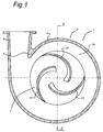
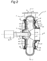
- Fig.'s 1 and 2 schematically depict an example of such a known
centrifugal pump 1, both Figures showing a cross-sectional view in different directions. Thepump 1 comprises apump housing 2 shaped like a volute (spiral casing). Thepump housing 2 comprises acircumferential wall 3, apump casing 20 and ashaft cover 40. Thecircumferential wall 3 comprises a spout-shaped outlet 5 attached tangentially to thecircumferential wall 3 . The junction between the inner surface of thetangential outlet 5 and the inner surface of thecircumferential wall 3 of thepump housing 2 defines what is known as acutwater 4. Thepump housing 2 also has anaxial inlet 6, shown inFig. 2 . - The
circumferential wall 3 may have a U-shaped or semicircular cross-section, comprising two (parallel)legs 31 extending in a radial inward direction and a middle part connecting the two legs forming theouter wall 32 of the circumferential wall. Thisouter wall 32 may be a straight part or may be curved. - The
outer wall 32 spirals outwardly about the axial rotation axis A of the pump 1 (defined below) towards thetangential outlet 5. - A
rotor 7 is attached in thepump housing 2 such that it may rotate about an axial rotation axis A. Therotor 7 comprisesrotor blades 15, ashaft shield 11 and asuction shield 12. Therotor 7 also comprises acentral boss 9 which may be fastened to a drive shaft (51). Theshaft shield 11 extends from thecentral boss 9. Theshaft shield 11 forms a first wall for delimiting the flow within therotor 7. Axially set apart from theshaft shield 11, therotor 7 has thesuction shield 12 which defines a second wall for delimiting the flow within therotor 7. Thesuction shield 12 has anaxial supply 14 which is aligned with the axial inlet of thepump housing 2. - A plurality of
rotor blades 15 are fastened between theshields rotor 7 comprises threerotor blades 15. Therotor blades 15 each extend substantially radial to the rotation axis A. Between the radial outer ends 17 of therotor 7 and the inner surface of thecircumferential wall 3 of thepump housing 2 there is acircumferential channel 19. - The
circumferential wall 3 of thepump housing 2 substantially closes the inner space of therotor 7 along its outer circumference between theshields - In order to provide a strong pump, the
pump housing 2 further comprises apump casing 20 and ashaft cover 40, both attached to thecircumferential wall 3. - The
pump casing 20 is attached to thepump housing 2, i.e. to thecircumferential wall 3, by suitable connection means 22. Thepump casing 20 has a central opening which may form theaxial supply 14 or may surround theaxial supply 14. Thepump casing 20 may comprise astepped part 23 and reinforcing ribs 21 (not shown in Fig.'s 1 and 2). The term pump casing in this text is used to refer to a part of thepump housing 2 extending between the central opening to thecircumferential wall 3. Thepump casing 20 may also be referred to as the suction cover orsuction lid 20. - The shaft cover 40 (or shaft lid 40) is also attached to the
circumferential wall 3 opposite thepump casing 20, by suitable connection means 42. Theshaft cover 40 also has a central opening to allow adrive axis 51 of apump motor 50 to be connected to therotor 7. - During operation, the
drive axis 51 and therotor 7 rotate about the rotation axis A. Between therotor blades 15, the mass to be pumped is forced radially outward into thepump housing 2 under the influence of centrifugal forces. Said mass is then entrained in the circumferential direction of thepump housing 2 toward thetangential outlet spout 5 of thepump housing 2. The pumped mass which, after leaving therotor 7, is entrained in the circumferential direction of thepump housing 2 flows largely out of the tangential outlet of thepump housing 2. A small amount of the entrained mass re-circulates, i.e. flows along thecutwater 4 back into thepump housing 2. - When such pumps are used for dredging, the pumps may be subjected to extreme wear, especially the
rotor 7 and thecircumferential wall 3. Therefore preferably wear resistant material is used. However, these materials are in general not well suited for construction purposes, as they are usually brittle. An example of such a material is white cast iron such as maxidur. - As a result of the pumping, high pressure will be generated forcing the
pump casing 20 outwardly. High loads may be transferred via connection means 22. FromFig. 2 it can be seen that these loads may introduce a bending moment in thecircumferential wall 3 of thepump housing 2, as theleg 31 to which thepump casing 20 is attached is forced in an outward direction. To prevent introducing a bending moment, or keeping the bending moment relatively small, in thecircumferential wall 3 of thepump housing 2, it is known to position the connection means 22 more outwardly than shown inFig. 2 , i.e. along the outer circumference of thecircumferential wall 3 of thepump housing 2, at the position where thecircumferential wall 3 is relatively thick (seen in the direction of the connection means 22) and is thus able to take up high loads. An example of this is the LSA-S Series Slurry Pumps of GIW Industries. - This will result in lower stresses in the
circumferential wall 3 of thepump housing 2 and reduces the chance of deformation of thecircumferential wall 3. - Further examples of centrifugal pumps and connection means for housings provided along the outer circumference are provided by
DE2541422A1 ,GB719285A US3018736 (closest prior art),US3265002 ,CN201661518 andFR567370A -
WO2009149511 shows a pump assembly with a pump housing comprising two casting parts which are joined together about the periphery of the two side casing parts, without the use of a circumferential wall as described above. The two side casing parts comprise apertures to allow the two side casing parts to be joined together by bolts. One of the side casing parts also comprises apertures for receiving liner locating and fixing pins for locating the main liner or volute and the pump outer casing relative to another. - It is an object to provide a pump housing and pump which is stiffer, stronger and thus more efficient. It is also an object to provide an improved method of manufacturing such a pump housing and pump.
- Therefore, according to a first aspect there is provided a pump housing comprising a circumferential wall, a pump casing and a shaft cover, wherein the pump casing is attached to the circumferential wall by a plurality of connection means, and wherein the pump casing comprises a central opening to form an axial supply of the pump housing for material to be pumped, the circumferential wall closing the pump housing along an outer circumference of the pump housing,
wherein the pump comprises a plurality of connection means connecting the pump casing to the circumferential wall,
characterized in that the connection means are positioned in groups along the circumference of the pump housing, wherein the groups are regularly distributed along the circumference of the pump housing. - By providing the connection means in groups, a group comprising two or more connection means, and distributing the groups at regular intervals along the circumference of the pump housing, a strong and stiff pump housing is created, which can also be manufactured in an advantageous way. Such connection means in groups are not present in
WO2009149511 , - The groups may be pairs comprising two connection means, whereby a pair is defined as two connection means with a distance between those two connection means which is at least 1/2 the distance between each connection means of that pair to the next closest connection means. This ratio may preferably be 1/3 or even 1/5.
- A group may also comprise more than two connection means, whereby a group is defined as a plurality of connection means whereby a largest distance between any two connection means of the group is at least 1/2 the distance between each connection means of that group to the next closest connection means of a different group. This ratio may preferably be 1/3 or even 1/5.
- The term regularly distributed is used to indicate that the groups or pairs are distributed along the circumference of the pump housing at substantially constant angles when seen from a centre point of the pump housing, i.e. at angles α equal to 360/n, n being an integer greater than 1, for
instance - The term connection means in this text is used to refer to connection means capable of securing the pump casing to the circumferential wall. The connection means are arranged to withstand forces pushing the pump casing and the circumferential wall away from each other, in particular in a direction perpendicular to the interface of the pump casing and the circumferential wall. Such forces are generated inside the pump housing as a result of increased pressure inside the pump housing when the pump is in operation.
- For instance, the connection means may be formed by a screw bolt and corresponding screw bolt receiving holes with an inner screw thread. It is noted that the receiving holes may be provided in the pump casing and the circumferential wall of which only the receiving holes in the circumferential wall are screw bolt receiving holes.
- According to an embodiment the pump casing comprises a plurality of reinforcing ribs positioned radially with respect to the central opening, wherein the connection means are positioned adjacent reinforcing ribs.
- By providing the connection means adjacent the reinforcing ribs, the pump is stronger and stiffer, which is beneficial to the performance of the pump. The connection means hold the pump casing in position. The connection means are now positioned close to the reinforcing ribs, i.e. at a position where the pump casing is relatively strong. This results in an improved stress distribution, making the pump relatively strong and stiff.
- The reinforcing ribs may extend from the axial supply towards the outer circumference of the pump casing. The ribs may have a triangular shape and may be orientated such that the height of the ribs reduces towards the outer circumference of the pump casing. There may be any suitable amount of ribs provided, such as eight, twelve or sixteen ribs. The ribs may be uniformly distributed.
- The circumferential wall closes the pump housing along its outer circumference, but it will be understood that the circumferential wall may also comprise an outlet for the pumped materials.
- The term adjacent is used to indicate that the distance taken along the perimeter of the pump casing between the connection means and the nearest reinforcing rib is at least 5 times smaller than the distance between the connection means and the second nearest reinforcing rib. Preferably, this distance may be at least 10 times smaller.
- According to an embodiment the connection means of a group are positioned on opposite sides of the adjacent reinforcing rib.
- The connection means forming a group or pair may be provided on opposite sides of the reinforcing ribs to provide a strong and symmetric construction. The connection means forming a pair may be positioned at the same distance from the associated reinforcing rib at opposite sides of the reinforcing rib.
- Each reinforcing
rib 21 may be provided with a pair of connection means 22, possibly with an exception for a minority of reinforcingribs 21, e.g. one or two reinforcingribs 21, which may be left without connection means 22 to meet certain constructional requirements or the like. - By placing connection means on either side of the reinforcing ribs the construction becomes even stiffer and the even stress distribution results in lower stresses.
- Instead of pairs, groups of connection means may be provided, wherein a group comprises two, three, four or more connection means to provide an even stronger pump housing.
- It is noted that although the connection means or pairs of connection means may be regularly distributed along the outer circumference, one or two connection means may be omitted, as already indicated above.
- Such a distribution provides a relatively strong and stiff pump and simplifies the design and manufacturing process. The circumferential wall of the pump housing may be casted. The connection means, which may be bolt receiving structures provided on the outside of the outer circumference may also function as casting inlets for the casting material (such as liquid steel) during the casting process.
- In case the connection means are provided in pairs, an additional advantage is provided. One casting inlet may then be provided for each pair. This allows a relatively large casting inlet, which is beneficial, as the casting material needs to be supplied to the mould sufficiently fast such that it can spread through the mould before it is solidified.
- According to an embodiment the connection means are positioned along the outer circumference of the pump and connect the pump casing to a radial outer wall of the circumferential wall.
- Providing the connection means along the outer circumference provides an even stronger and stiffer pump as bending moments in the circumferential wall, especially in the radial inwardly protruding legs of the circumferential wall are minimized and the connection means engage the circumferential wall at the outer wall, i.e. at a position where the circumferential wall is relatively thick in the axial direction.
- According to an embodiment the connection means are formed by a connection member, such as a bolt, and bolt receiving holes provided on the circumferential wall and bolt receiving holes provided on the pump casing.
- The connection member may be a screw bolt. One or both of the bolt receiving holes may be a screw bolt receiving hole comprising an inner thread to receive the screw bolt and hold the screw bolt in position. In order to provide a reliable inner thread a soft insert may be used. The material used for the pump housing is typically wear resistant material, i.e. it is hard but brittle, which is thus, mechanically and production wise, not well suited for threaded holes. An example of such a material is steel S235. To overcome this, a soft insert may be applied which is more suitable for providing an inner thread.
- The bolt receiving holes provided on the circumferential wall and the bolt receiving holes provided on the pump casing are aligned with respect to each other.
- According to an embodiment the circumferential wall comprises bolt receiving structures provided on the outer circumference of the circumferential wall.
- The bolt receiving structures may protrude in a radial outward direction. The bolt receiving structures may be integrally formed with the circumferential wall. This provides a robust circumferential wall. This embodiment also provides advantages for the manufacturing process, as will be described in more detail below.
- According to an embodiment each bolt receiving structure comprises at least two bolt receiving holes.
- In order to prevent cracks and the like in the bolt receiving structures, the bolt receiving holes may not be positioned too close to each other, especially when soft inserts are used. As a consequence, the bolt receiving structures may not be too small. Such bolt receiving structures provide advantages in the manufacturing process. Also, such a design minimizes the amount of material that is needed.
- According to an aspect there is provided a pump comprising a pump housing according to the above.
- According to an aspect there is provided a circumferential wall of a pump housing, the circumferential wall comprises a spiral shaped outer wall and two inwardly protruding legs attached to the outer wall, wherein the circumferential wall comprises bolt receiving holes which are positioned in groups along the circumference of the circumferential wall, wherein the groups are regularly distributed along the circumference of the circumferential wall. The bolt receiving holes may be screw bolt receiving holes provided with an inner thread.
- According to an aspect there is provided a method of manufacturing a circumferential wall for a pump housing, and wherein the circumferential wall comprises bolt receiving holes provided on the outside of the circumferential wall, wherein the method comprises:
- providing a mould for the circumferential wall, the mould comprising a plurality of casting openings,
- filling the mould with a liquid casting material by supplying the casting material to the mould via the casting openings,
- allowing the casting material to solidify in the mould,
- removing the mould,
- According to an embodiment the circumferential wall comprises bolt receiving structures provided on the outer circumference of the circumferential wall, which bolt receiving structures coincide with the casting openings and/or function as risers during casting.
- The design of the circumferential wall in combination with the positioning of the casting openings provides an advantageous method of manufacturing a circumferential wall. The bolt receiving structures, which may be formed as a structure protruding in a radial outward direction from the spiral shaped outer wall provides an optimal structure for the casting openings of the mould. Also, such bolt receiving structures are suitable to be used as risers, especially since the connecting means are provided in groups making the bolt receiving structures relatively large. Preferably, risers are not too small as this will cause the casting material to solidify too quickly prohibiting the riser to function properly.
- According to an embodiment each bolt receiving structure comprises at least two bolt receiving holes.
- Such bolt receiving structures will typically be larger than bolt receiving structures for one bolt receiving hole, making these bolt receiving structures even more suitable to be used as casting inlets, as relative large quantities of casting material may be supplied into the mould via each cast opening, allowing a fast casting process.
- According to an embodiment the casting material is one of steel, cast steel, grey or white cast iron.
- Embodiments will now be described, by way of example only, with reference to the accompanying schematic drawings in which corresponding reference symbols indicate corresponding parts, and in which:
-
FIG. 1 and2 schematically show two different cross-sectional views of a pump according to the prior art, -
FIG. 3 schematically shows a perspective view of a pump housing according to an embodiment, -
Fig. 4 schematically depicts a side view of a pump housing according to an embodiment, -
FIG. 5 schematically depicts a detail of the pump housing according to an embodiment, and - Fig.'s 6a - b schematically depict a pump housing according to different embodiments.
- The figures are meant for illustrative purposes only, and do not serve as restriction of the scope or the protection as laid down by the claims.
- The embodiments will now be described with reference to the figures. Fig.'s 1 and 2 show a pump according to the prior art and were discussed above.
-
Fig. 3 shows an embodiment of apump 1, a centrifugal pump, comprising apump housing 2 with acircumferential wall 3, apump casing 20 and ashaft cover 40 as described above. The circumferential wall spirals outwardly to form atangential outlet 5, as shown in the figures. - The
pump housing 2 may be suitable for pumping a slurry comprising a mixture of water and dredged materials, such as sand, rocks etc. Therefore, thepump 1 is arranged to accommodate arotor 7 comprisingrotor blades 15, ashaft shield 11 and asuction shield 12 as described above. - The
pump casing 20 is formed as a lid arranged to cover thepump housing 2 and provide thepump housing 2 with additional strength. Thepump casing 20 has a substantially disc shapedpart 26, although the disc shapedpart 26 may not have a circular outer circumference, as it may deviate from a circular shape at the position of theoutlet 5. In the centre of the pump casing 20 acentral opening 27 is provided to allow mass to be pumped to enter thepump housing 2 via theaxial inlet 6 andaxial supply 14. At thecentral opening 27 aninlet conduit 28 may be formed as integral part of thepump casing 20, theinlet conduit 28 protruding from thepump casing 20 in the direction of the axial rotation axis A, away from the shaft cover 40 (not shown inFig. 3 ). Theinlet conduit 28 may form theaxial inlet 6. - The
pump casing 20 comprises a steppedpart 23 forming a transition between the disc shapedpart 26 and theinlet conduit 28, making thepump casing 20 strong. Furthermore, a plurality of reinforcingribs 21 are provided. Each reinforcingrib 21 is substantially perpendicular with respect to the disc shapedpart 26 and each reinforcingrib 21 is orientated in a different radial direction. - Also provided is a
shaft cover 40 forming the counterpart of thepump casing 20, positioned on the shaft side of the pump housing. Theshaft cover 40 also comprises a central opening to allow thedrive shaft 51 ofmotor 50 to pass through and drive therotor 7 to rotate about axis A. - As shown in
Fig. 3 , the connection means 22 (connecting thepump casing 20 to the circumferential wall 3) are provided in groups, such as pairs, positioned regularly, i.e. at regular intervals. This will be explained in more detail below with reference toFig. 6 . - The connection means 22 are also positioned adjacent the reinforcing
ribs 21. The term adjacent is used her to indicate that that the connection means 22 are positioned close to a reinforcingrib 21, for instance at least 5 times, preferably at least 10 times closer to the closest reinforcingrib 21 than to the secondclosest reinforcing rib 21. - The connection means 22 may also be positioned close to the outer circumference of the
pump casing 20, such that the connection means 22 engage thecircumferential wall 3 at the position of the radialouter wall 32. In this case, the term 'close to' is used to indicate that the distance between the connection means 22 and the outer circumference of thepump casing 20 is less than 25%, or preferably less than 10%, of the radius of thepump casing 20, measured from the centre of thecentral opening 27 to the outer circumference of the disc shapedpart 26. - According to the embodiment shown in
Fig. 3 , the connection means 22 are provided in pairs, i.e. each reinforcingrib 21 has two associated, adjacent, connection means 20, which are provided symmetrically on both sides of the reinforcingrib 21. Of course, more than two connection means 22 may be provided in association with one reinforcingrib 21. In general, a group of connection means 22 may be provided in association with a reinforcingrib 21. - In
Fig. 3 , connection means 22 are provided for each reinforcingrib 21. However, according an embodiment, some reinforcingribs 21 may be without associated connection means 22, for instance the reinforcing ribs 21' near theoutlet 5. - The connection means 22 may be any suitable connection means 22, such as clamping devices clamping the pump casing against the
circumferential wall 3 or clamping thepump casing 20 and theshaft cover 40 together squeezing them against thecircumferential wall 3. - As shown in the Figures, the connection means 22 may be formed by a
connection member 223, such as a bolt, and a correspondingbolt receiving hole 224 provided on thecircumferential wall 3 and abolt receiving hole 222 provided on thepump casing 20. This is shown in more detail inFig. 5 , showing part of thecircumferential wall 3 and thepump casing 20. - The
circumferential wall 3 may be provided with bolt receiving members or bolt receivingstructures 221 provided on the outer circumference of thecircumferential wall 3, protruding from the spiral outer shape of theouter wall 32 of thecircumferential wall 3, and comprising bolt receiving holes 21. The dashed line L shown inFig. 5 shows the contour of thecircumferential wall 3 as it would be without thebolt receiving structure 221, clearly showing that thebolt receiving structure 221 protrudes from the outer wall of thecircumferential wall 3. - One bolt receiving structure or
structure 221 may comprise one or two bolt receiving holes 21. - The
bolt receiving holes pump 1 will try to move thepump casing 20. -
Fig. 5 further shows that thepump casing 20 may compriseannular slots 241 in which sealingmembers 242, such as O-rings, may be positioned to provide a fluid-tight connection between thecircumferential wall 3 and thepump casing 20. - The
circumferential wall 3 may be provided withsoft inserts 228 which are suitable for forming a threadedbolt receiving hole 224 therein. -
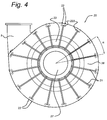
Fig. 4 shows a side view of thepump 1 in the direction of theaxial supply 14. It can be seen that the reinforcingribs 21 are all orientated in a different radial direction at regular mutual angles α. The reinforcingrib 21 or reinforcingribs 21 close to theoutlet 5 may be a bit longer or shorter in radial direction to follow the irregularity of the outer circumference of thepump casing 20 and thecircumferential wall 3. - The distribution of the connection means 22 will now be explained in more detailwith reference to
Fig. 6a- b , showing a view of thepump housing 20 in the direction of the rotation axis A. - As shown, the connection means 22 may be positioned in groups, such as pairs (
Fig. 6a ) or in larger groups, for instance comprising four connection means 22, as shown inFig. 6b . The groups are positioned along the circumference of thepump housing 2 and are regularly distributed along the circumference of thepump housing 2. A group may be defined as a number of connection means 22 that are relatively close to each other compared to other connection means 22 which thus not belong to that group. A group may be defined as a plurality of connection means 22 whereby a largest distance between any two connection means of the group (d1 inFig. 6b ) is at least 1/2 the distance between each connection means of that group to the next closest connection means of a different group (d2 inFig. 6b ). This ratio may preferably be 1/3 or even 1/5. This definition also applies to a group of two connection means 22.Fig. 6a also shows distances d1 and d2, whereby d1 < ½d2, preferably d1 < 1/3 d2 or d1 < 1/5 d2. - The term regularly distributed is used to indicate that the groups are distributed along the circumference of the
pump housing 2 at substantially constant angles α as shown in Fig.'s 6a - b when seen from a centre point of thepump housing 2. In Fig.'s 6a - b there are sixteen groups at a mutual angle α = (360/16)°. The term substantially constant is used to indicate that the different angles deviate less than 5°, preferably less than 2° with respect to each other. - Alternatively, the term regularly distributed may be used to indicate that the groups are distributed along the circumference of the
pump housing 2 at substantially constant intervals. The term constant is used to indicate that these distances do not deviate more than 15%, preferably less than 10%. - According to an embodiment, the groups are regularly distributed along a substantial part of the circumference of the
pump housing 2, whereby the substantial part of the circumference of thepump housing 2 forms at least 75% of the total circumference, so is at least 270°. - Manufacturing a
pump 1 or apump housing 2 as described above may involve casting one or more of the pump parts, such as thecircumferential wall 3. - The
bolt receiving structures 221 or bolt receiving structures provided on the outer circumference of thecircumferential wall 3, protruding from the outer wall of thecircumferential wall 3 allow for an advantageous casting process. - The casting mould is provided with casting openings to supply casting material into the mould. The
bolt receiving structures 221 can be aligned with the casting openings of the mould providing an excellent structure for supplying the casting material into the casting mould. This saves material and thus cost with respect to supplying casting material at other positions. - Also, the
bolt receiving structures 221 can advantageously function as risers. During the casting process, the casing material inside the mould will solidify and thus shrink. Risers can function as a buffer reservoir for casting material. Once the material inside the mould has shrunk, the space in between the mould and the shrunk casting material will be filled with casting material from the risers. The risers may not be too small, as this will cause the casting material to cool down relatively quickly compared to the cooling of the rest of the casting material in the mould. - It is noted that all the configurations and embodiments of the connection means as described above may also be applied to the connection means 42 connecting the
shaft cover 40 to thecircumferential wall 3. These connection means 42 may also be positioned in groups along the circumference of thepump housing 2, wherein the groups are regularly distributed along the circumference of thepump housing 2. Theshaft cover 40 may comprises a plurality of reinforcing ribs positioned radially with respect to a central opening for the drive shaft, wherein the connection means 42 are positioned adjacent the reinforcing ribs. The connection means 42 of a group may be positioned on opposite sides of the adjacent reinforcing rib. The connection means may be positioned along the outer circumference of thepump 1 and connect theshaft cover 40 to a radialouter wall 32 of thecircumferential wall 3. The connection means 42 may be formed by a connection member, such as a bolt, and bolt receiving holes provided on thecircumferential wall 3 and bolt receiving holes provided on theshaft cover 40. Thecircumferential wall 3 may comprise bolt receiving structures provided on the outer circumference of the circumferential wall. Each bolt receiving structure may comprise two bolt receiving holes. - The embodiments described provide a pump, which is relatively strong and stiff. The pump can be casted in an efficient way, still resulting in a pump which is strong and stiff.
- The descriptions above are intended to be illustrative, not limiting. It will be apparent to the person skilled in the art that alternative and equivalent embodiments of the invention can be conceived and reduced to practice, without departing from the scope of the claims set out below.
Claims (8)
- Pump housing (2) comprising a circumferential wall (3), a pump casing (20) and a shaft cover (40), wherein the pump casing (20) is attached to the circumferential wall (3), and wherein the pump casing (20) comprises a central opening (27) to form an axial supply (14) of the pump housing (2) for material to be pumped, the circumferential wall (3) being an outer wall of the pump housing (2),
wherein the pump housing (2) comprises connection means (22), connecting the pump casing (20) to the circumferential wall (3),
wherein the connection means (22) are positioned in groups along the circumference of the pump housing (2), each group comprising a plurality of connection means (22), wherein the groups are regularly distributed along the circumference of the pump housing (2), wherein the connection means (22) are formed by bolts, and bolt receiving holes (224) provided on the circumferential wall (3) and bolt receiving holes (222) provided on the pump casing (20), wherein the circumferential wall (3) comprises bolt receiving structures (221) provided on the outer circumference of the circumferential wall (3), wherein the bolt receiving structures protrude in a radially outward direction, characterized in that each bolt receiving structure (221) comprises at least two bolt receiving holes (224). - Pump housing (2) according to claim 1, wherein the pump casing (20) comprises a plurality of reinforcing ribs (21) positioned radially with respect to the central opening (27), wherein the connection means (22) are positioned adjacent reinforcing ribs (21).
- Pump housing (2) according to claim 2, wherein the connection means (22) of a group are positioned on opposite sides of the adjacent reinforcing rib (21).
- Pump housing (2) according to any one of the preceding claims, wherein the connection means (22) are positioned along the outer circumference of the pump housing (2) and connect the pump casing (20) to a radial outer wall (32) of the circumferential wall (3).
- Pump (1) comprising a pump housing (2) according to any one of the preceding claims 1 - 4.
- Circumferential wall (3) of a pump housing (2), the circumferential wall (3) comprises a spiral shaped outer wall (32) and two inwardly protruding legs (31) attached to the outer wall (32), wherein the circumferential wall (3) comprises bolt receiving structures (221) provided on the outer circumference of the circumferential wall (3), wherein the bolt receiving structures protrude in a radially outward direction, the bolt receiving structures (221) comprising bolt receiving holes (224) characterized in that the bolt receiving structures (221) are positioned in groups along the circumference of the circumferential wall (3), wherein the groups are regularly distributed along the circumference of the circumferential wall (3), wherein each bolt receiving structure (221) comprises at least two bolt receiving holes (224).
- Method of manufacturing a circumferential wall (3) for a pump housing (2), wherein the circumferential wall (3) comprises bolt receiving holes (224) provided on the outside of the circumferential wall (33), wherein the method comprises:- providing a mould for the circumferential wall (3), the mould comprising a plurality of casting openings,- filling the mould with a liquid casting material by supplying the casting material to the mould via the casting openings,- allowing the casting material to solidify in the mould,- removing the mould,characterized by the bolt receiving holes (224) being positioned in groups along the circumference of the circumferential wall (3), wherein the groups are regularly distributed along the circumference of the circumferential wall (3), wherein the circumferential wall (3) comprises bolt receiving structures (221) provided on the outer circumference of the circumferential wall (3), wherein the bolt receiving structures (221) protrude in a radially outward direction, wherein each bolt receiving structure (221) comprises at least two bolt receiving holes (224), which bolt receiving structures coincide with the casting openings and/or function as risers during casting.
- Method according to claim 7, wherein the casting material is one of steel, cast steel, grey or white cast iron.
Applications Claiming Priority (2)
| Application Number | Priority Date | Filing Date | Title |
|---|---|---|---|
| NL2008180A NL2008180C2 (en) | 2012-01-25 | 2012-01-25 | Pump and a method of manufacturing such a pump. |
| PCT/NL2013/050030 WO2013112045A1 (en) | 2012-01-25 | 2013-01-23 | Pump and a method of manufacturing such a pump |
Publications (3)
| Publication Number | Publication Date |
|---|---|
| EP2807376A1 EP2807376A1 (en) | 2014-12-03 |
| EP2807376B1 true EP2807376B1 (en) | 2016-01-20 |
| EP2807376B8 EP2807376B8 (en) | 2016-03-16 |
Family
ID=47710276
Family Applications (1)
| Application Number | Title | Priority Date | Filing Date |
|---|---|---|---|
| EP13703902.0A Active EP2807376B8 (en) | 2012-01-25 | 2013-01-23 | Pump and a method of manufacturing such a pump |
Country Status (7)
| Country | Link |
|---|---|
| US (1) | US9726193B2 (en) |
| EP (1) | EP2807376B8 (en) |
| CN (1) | CN104204534B (en) |
| ES (1) | ES2563236T3 (en) |
| NL (1) | NL2008180C2 (en) |
| WO (1) | WO2013112045A1 (en) |
| ZA (1) | ZA201405507B (en) |
Cited By (1)
| Publication number | Priority date | Publication date | Assignee | Title |
|---|---|---|---|---|
| GB2548472B (en) * | 2016-02-09 | 2021-07-28 | Brunswick Corp | Centrifugal pumps having anti-air-locking features |
Families Citing this family (7)
| Publication number | Priority date | Publication date | Assignee | Title |
|---|---|---|---|---|
| USD751685S1 (en) * | 2013-08-06 | 2016-03-15 | Shinano Kenshi Co., Ltd. | Blower |
| PE20170619A1 (en) * | 2014-07-31 | 2017-06-02 | Weir Minerals Australia Ltd | PUMP LINING |
| CN106968984B (en) * | 2015-12-11 | 2020-10-23 | 松下知识产权经营株式会社 | Turbine engine |
| US10339962B2 (en) | 2017-04-11 | 2019-07-02 | Texas Instruments Incorporated | Methods and apparatus for low cost voice activity detector |
| NL2022881B1 (en) | 2019-04-05 | 2020-10-12 | Ihc Holland Ie Bv | Pump |
| DE102019115741A1 (en) * | 2019-06-11 | 2020-12-17 | Ebm-Papst Landshut Gmbh | Stiffened fan housing part for arrangement on a gas fan |
| RU195238U1 (en) * | 2019-10-03 | 2020-01-17 | Акционерное общество (АО) "Турбонасос" | CENTRIFUGAL PUMP BODY FOR TRANSFER OF ABRASIVE CONTAINING MEDIA |
Family Cites Families (30)
| Publication number | Priority date | Publication date | Assignee | Title |
|---|---|---|---|---|
| NL111055C (en) | ||||
| FR567370A (en) | 1923-06-13 | 1924-02-29 | Reinforced lead pumps for acids | |
| US2537084A (en) * | 1948-09-04 | 1951-01-09 | Morris Machine Works | Fabricated centrifugal pump |
| GB719285A (en) | 1951-10-03 | 1954-12-01 | British Thomson Houston Co Ltd | Improvements in rotary liquid pumps |
| US2856858A (en) * | 1953-07-13 | 1958-10-21 | Grace W R & Co | Centrifugal pump |
| US3018736A (en) | 1954-01-04 | 1962-01-30 | Hetherington & Berner Inc | Dredge pump |
| US2976809A (en) | 1954-08-11 | 1961-03-28 | Buschhorn Walther | Centrifugal pump and method of its production |
| DE1112897B (en) | 1958-05-20 | 1961-08-17 | Schauenburg Hans Georg | Pump housing with housing jacket made up of rings |
| GB867802A (en) | 1959-07-18 | 1961-05-10 | Mervyn Joseph Alexander Carrie | Improvements in rotary gravel or like pumps |
| US3265002A (en) | 1961-01-13 | 1966-08-09 | Res & Dev Pty Ltd | Centrifugal pumps and the like |
| US3333872A (en) * | 1964-11-18 | 1967-08-01 | Standard Fire Prot Equipment C | Mechanical pipe joint construction |
| US3473573A (en) * | 1966-10-06 | 1969-10-21 | Baker Mfg Co | Well cap and seal therefor |
| US3465681A (en) * | 1967-08-24 | 1969-09-09 | March Mfg Co | Magnetically-coupled pump with detachable motor |
| SE428957B (en) * | 1975-06-02 | 1983-08-01 | Warman Int Ltd | INTERIOR LINED HIGH PRESSURE PUMP HOUSE |
| SE429255B (en) * | 1975-06-13 | 1983-08-22 | Warman Int Ltd | HOUSES AND LINES FOR SNACK TYPE CENTRIFUGAL PUMPS |
| DE2541422B2 (en) | 1975-09-17 | 1979-04-05 | Schmalenberger Gmbh & Co, 7400 Tuebingen | Motor-pump unit with a pump housing consisting of at least two housing halves |
| GB1517400A (en) | 1975-12-17 | 1978-07-12 | Mitsui Mining & Smelting Co | Impeller-type pump |
| DE2837986C2 (en) * | 1978-08-31 | 1984-04-12 | Elektro-Thermit Gmbh, 4300 Essen | Casting mold for aluminothermic rail connection welding |
| US6267268B1 (en) * | 1999-08-31 | 2001-07-31 | The Coca-Cola Company | Mounting block for syrup pump and accessories |
| GB2391266A (en) * | 1999-10-06 | 2004-02-04 | Vaughan Co | Impeller and intake arrangement for a centrifugal pump |
| US7470106B1 (en) * | 2001-07-10 | 2008-12-30 | Townley Manufacturing, Inc. | Centrifugal slurry pump |
| JP4484470B2 (en) * | 2002-10-23 | 2010-06-16 | エドワーズ株式会社 | Molecular pump and flange |
| DE602006010075D1 (en) | 2006-09-18 | 2009-12-10 | Ihc Holland Ie Bv | Centrifugal pump and its application |
| EP1906029B1 (en) | 2006-09-19 | 2009-12-16 | IHC Holland IE B.V. | Centrifugal pump having an inner casing and an outer casing |
| DE202007018626U1 (en) | 2007-07-19 | 2009-04-02 | Elektror K.W. + M. Müller GmbH | blower |
| CN201106566Y (en) * | 2007-09-05 | 2008-08-27 | 林心怡 | Improved structure of wastewater treatment pump |
| PE20110032A1 (en) * | 2008-06-13 | 2011-02-11 | Weir Minerals Australia Ltd | IMPROVEMENTS RELATED TO PUMP SEAL ASSEMBLIES |
| CN201273302Y (en) * | 2008-09-19 | 2009-07-15 | 沈阳鼓风机集团有限公司 | Assembly structure for head and barrel of barrel-type compressor |
| FR2949517B1 (en) | 2009-08-25 | 2011-10-21 | Snecma | TURBOMACHINE HOUSING WITH REINFORCED SEALING |
| CN201661518U (en) * | 2010-02-03 | 2010-12-01 | 李正奇 | Water outlet section for multistage centrifugal pump |
-
2012
- 2012-01-25 NL NL2008180A patent/NL2008180C2/en not_active IP Right Cessation
-
2013
- 2013-01-23 CN CN201380016384.XA patent/CN104204534B/en active Active
- 2013-01-23 ES ES13703902.0T patent/ES2563236T3/en active Active
- 2013-01-23 WO PCT/NL2013/050030 patent/WO2013112045A1/en active Application Filing
- 2013-01-23 EP EP13703902.0A patent/EP2807376B8/en active Active
- 2013-01-23 US US14/374,597 patent/US9726193B2/en active Active
-
2014
- 2014-07-25 ZA ZA2014/05507A patent/ZA201405507B/en unknown
Cited By (1)
| Publication number | Priority date | Publication date | Assignee | Title |
|---|---|---|---|---|
| GB2548472B (en) * | 2016-02-09 | 2021-07-28 | Brunswick Corp | Centrifugal pumps having anti-air-locking features |
Also Published As
| Publication number | Publication date |
|---|---|
| US20140348645A1 (en) | 2014-11-27 |
| EP2807376A1 (en) | 2014-12-03 |
| EP2807376B8 (en) | 2016-03-16 |
| US9726193B2 (en) | 2017-08-08 |
| NL2008180C2 (en) | 2013-07-29 |
| ES2563236T3 (en) | 2016-03-11 |
| CN104204534A (en) | 2014-12-10 |
| CN104204534B (en) | 2017-10-17 |
| ZA201405507B (en) | 2015-10-28 |
| WO2013112045A1 (en) | 2013-08-01 |
Similar Documents
| Publication | Publication Date | Title |
|---|---|---|
| EP2807376B1 (en) | Pump and a method of manufacturing such a pump | |
| RU2551909C2 (en) | Centrifugal impeller and turbine machine | |
| US7780406B2 (en) | Molded pump | |
| CA2831985C (en) | An improved impeller for a centrifugal slurry pump | |
| CA2791079C (en) | Pump intake device | |
| US9410529B2 (en) | Rotor blade for a wind turbine | |
| CA1270148A (en) | Vane core assembly for use in making centrifugal elastomer-coated impellers | |
| CN104603451B (en) | A kind of impeller unit for hydraulic fluid machine | |
| KR102546910B1 (en) | 3D plastic impeller manufacturing method and impeller for centrifugal pump | |
| EP1028256B1 (en) | Impeller for electric automotive fuel pump | |
| CN104747457B (en) | Modified structure of magnetic driving pumping | |
| US20110123337A1 (en) | Centrifugal pump impeller | |
| US20110182734A1 (en) | Centrifugal pump impeller | |
| CN203067340U (en) | Efficient asymmetric guide vane body matched with annular pumping chamber | |
| JP5984588B2 (en) | Water pump impeller | |
| US1107591A (en) | Pump construction. | |
| CA2667497C (en) | Hydraulic machine | |
| US11885345B2 (en) | Pump | |
| CN108506217A (en) | A kind of multistage combined centrifugal water pump | |
| CN116806292A (en) | Main gasket for pump | |
| CN202946437U (en) | Second-generation nuclear primary pump thrust bearing oil impeller | |
| CN115507060A (en) | Pump housing assembly | |
| WO2018049439A1 (en) | Volute liner arrangement | |
| CN109209514A (en) | The turbine of the axial flow turbo-machine of turbocharger flows into shell | |
| Yedidiah et al. | Axial and Radial Thrust and Balancing |
Legal Events
| Date | Code | Title | Description |
|---|---|---|---|
| PUAI | Public reference made under article 153(3) epc to a published international application that has entered the european phase |
Free format text: ORIGINAL CODE: 0009012 |
|
| 17P | Request for examination filed |
Effective date: 20140822 |
|
| AK | Designated contracting states |
Kind code of ref document: A1 Designated state(s): AL AT BE BG CH CY CZ DE DK EE ES FI FR GB GR HR HU IE IS IT LI LT LU LV MC MK MT NL NO PL PT RO RS SE SI SK SM TR |
|
| DAX | Request for extension of the european patent (deleted) | ||
| GRAP | Despatch of communication of intention to grant a patent |
Free format text: ORIGINAL CODE: EPIDOSNIGR1 |
|
| INTG | Intention to grant announced |
Effective date: 20150731 |
|
| GRAS | Grant fee paid |
Free format text: ORIGINAL CODE: EPIDOSNIGR3 |
|
| GRAA | (expected) grant |
Free format text: ORIGINAL CODE: 0009210 |
|
| AK | Designated contracting states |
Kind code of ref document: B1 Designated state(s): AL AT BE BG CH CY CZ DE DK EE ES FI FR GB GR HR HU IE IS IT LI LT LU LV MC MK MT NL NO PL PT RO RS SE SI SK SM TR |
|
| REG | Reference to a national code |
Ref country code: GB Ref legal event code: FG4D |
|
| REG | Reference to a national code |
Ref country code: CH Ref legal event code: EP |
|
| REG | Reference to a national code |
Ref country code: IE Ref legal event code: FG4D |
|
| GRAT | Correction requested after decision to grant or after decision to maintain patent in amended form |
Free format text: ORIGINAL CODE: EPIDOSNCDEC |
|
| REG | Reference to a national code |
Ref country code: AT Ref legal event code: REF Ref document number: 771865 Country of ref document: AT Kind code of ref document: T Effective date: 20160215 |
|
| RAP2 | Party data changed (patent owner data changed or rights of a patent transferred) |
Owner name: IHC HOLLAND IE B.V. |
|
| REG | Reference to a national code |
Ref country code: DE Ref legal event code: R096 Ref document number: 602013004739 Country of ref document: DE |
|
| REG | Reference to a national code |
Ref country code: ES Ref legal event code: FG2A Ref document number: 2563236 Country of ref document: ES Kind code of ref document: T3 Effective date: 20160311 |
|
| REG | Reference to a national code |
Ref country code: DE Ref legal event code: R082 Ref document number: 602013004739 Country of ref document: DE Representative=s name: KILBURN & STRODE LLP, NL Ref country code: DE Ref legal event code: R082 Ref document number: 602013004739 Country of ref document: DE Representative=s name: KILBURN & STRODE LLP, GB Ref country code: DE Ref legal event code: R081 Ref document number: 602013004739 Country of ref document: DE Owner name: IHC HOLLAND IE B.V., NL Free format text: FORMER OWNER: IHC HOLLAND IE N.V., SLIEDRECHT, NL |
|
| REG | Reference to a national code |
Ref country code: NL Ref legal event code: FP |
|
| REG | Reference to a national code |
Ref country code: LT Ref legal event code: MG4D |
|
| REG | Reference to a national code |
Ref country code: AT Ref legal event code: MK05 Ref document number: 771865 Country of ref document: AT Kind code of ref document: T Effective date: 20160120 |
|
| PG25 | Lapsed in a contracting state [announced via postgrant information from national office to epo] |
Ref country code: HR Free format text: LAPSE BECAUSE OF FAILURE TO SUBMIT A TRANSLATION OF THE DESCRIPTION OR TO PAY THE FEE WITHIN THE PRESCRIBED TIME-LIMIT Effective date: 20160120 Ref country code: NO Free format text: LAPSE BECAUSE OF FAILURE TO SUBMIT A TRANSLATION OF THE DESCRIPTION OR TO PAY THE FEE WITHIN THE PRESCRIBED TIME-LIMIT Effective date: 20160420 Ref country code: IT Free format text: LAPSE BECAUSE OF FAILURE TO SUBMIT A TRANSLATION OF THE DESCRIPTION OR TO PAY THE FEE WITHIN THE PRESCRIBED TIME-LIMIT Effective date: 20160120 Ref country code: FI Free format text: LAPSE BECAUSE OF FAILURE TO SUBMIT A TRANSLATION OF THE DESCRIPTION OR TO PAY THE FEE WITHIN THE PRESCRIBED TIME-LIMIT Effective date: 20160120 Ref country code: GR Free format text: LAPSE BECAUSE OF FAILURE TO SUBMIT A TRANSLATION OF THE DESCRIPTION OR TO PAY THE FEE WITHIN THE PRESCRIBED TIME-LIMIT Effective date: 20160421 |
|
| PG25 | Lapsed in a contracting state [announced via postgrant information from national office to epo] |
Ref country code: PT Free format text: LAPSE BECAUSE OF FAILURE TO SUBMIT A TRANSLATION OF THE DESCRIPTION OR TO PAY THE FEE WITHIN THE PRESCRIBED TIME-LIMIT Effective date: 20160520 Ref country code: LV Free format text: LAPSE BECAUSE OF FAILURE TO SUBMIT A TRANSLATION OF THE DESCRIPTION OR TO PAY THE FEE WITHIN THE PRESCRIBED TIME-LIMIT Effective date: 20160120 Ref country code: RS Free format text: LAPSE BECAUSE OF FAILURE TO SUBMIT A TRANSLATION OF THE DESCRIPTION OR TO PAY THE FEE WITHIN THE PRESCRIBED TIME-LIMIT Effective date: 20160120 Ref country code: SE Free format text: LAPSE BECAUSE OF FAILURE TO SUBMIT A TRANSLATION OF THE DESCRIPTION OR TO PAY THE FEE WITHIN THE PRESCRIBED TIME-LIMIT Effective date: 20160120 Ref country code: IS Free format text: LAPSE BECAUSE OF FAILURE TO SUBMIT A TRANSLATION OF THE DESCRIPTION OR TO PAY THE FEE WITHIN THE PRESCRIBED TIME-LIMIT Effective date: 20160520 Ref country code: LT Free format text: LAPSE BECAUSE OF FAILURE TO SUBMIT A TRANSLATION OF THE DESCRIPTION OR TO PAY THE FEE WITHIN THE PRESCRIBED TIME-LIMIT Effective date: 20160120 Ref country code: AT Free format text: LAPSE BECAUSE OF FAILURE TO SUBMIT A TRANSLATION OF THE DESCRIPTION OR TO PAY THE FEE WITHIN THE PRESCRIBED TIME-LIMIT Effective date: 20160120 Ref country code: PL Free format text: LAPSE BECAUSE OF FAILURE TO SUBMIT A TRANSLATION OF THE DESCRIPTION OR TO PAY THE FEE WITHIN THE PRESCRIBED TIME-LIMIT Effective date: 20160120 |
|
| REG | Reference to a national code |
Ref country code: CH Ref legal event code: PL |
|
| REG | Reference to a national code |
Ref country code: DE Ref legal event code: R097 Ref document number: 602013004739 Country of ref document: DE |
|
| PG25 | Lapsed in a contracting state [announced via postgrant information from national office to epo] |
Ref country code: EE Free format text: LAPSE BECAUSE OF FAILURE TO SUBMIT A TRANSLATION OF THE DESCRIPTION OR TO PAY THE FEE WITHIN THE PRESCRIBED TIME-LIMIT Effective date: 20160120 Ref country code: LI Free format text: LAPSE BECAUSE OF NON-PAYMENT OF DUE FEES Effective date: 20160131 Ref country code: DK Free format text: LAPSE BECAUSE OF FAILURE TO SUBMIT A TRANSLATION OF THE DESCRIPTION OR TO PAY THE FEE WITHIN THE PRESCRIBED TIME-LIMIT Effective date: 20160120 Ref country code: MC Free format text: LAPSE BECAUSE OF FAILURE TO SUBMIT A TRANSLATION OF THE DESCRIPTION OR TO PAY THE FEE WITHIN THE PRESCRIBED TIME-LIMIT Effective date: 20160120 Ref country code: CH Free format text: LAPSE BECAUSE OF NON-PAYMENT OF DUE FEES Effective date: 20160131 |
|
| REG | Reference to a national code |
Ref country code: IE Ref legal event code: MM4A |
|
| PLBE | No opposition filed within time limit |
Free format text: ORIGINAL CODE: 0009261 |
|
| STAA | Information on the status of an ep patent application or granted ep patent |
Free format text: STATUS: NO OPPOSITION FILED WITHIN TIME LIMIT |
|
| PG25 | Lapsed in a contracting state [announced via postgrant information from national office to epo] |
Ref country code: SK Free format text: LAPSE BECAUSE OF FAILURE TO SUBMIT A TRANSLATION OF THE DESCRIPTION OR TO PAY THE FEE WITHIN THE PRESCRIBED TIME-LIMIT Effective date: 20160120 Ref country code: RO Free format text: LAPSE BECAUSE OF FAILURE TO SUBMIT A TRANSLATION OF THE DESCRIPTION OR TO PAY THE FEE WITHIN THE PRESCRIBED TIME-LIMIT Effective date: 20160120 Ref country code: SM Free format text: LAPSE BECAUSE OF FAILURE TO SUBMIT A TRANSLATION OF THE DESCRIPTION OR TO PAY THE FEE WITHIN THE PRESCRIBED TIME-LIMIT Effective date: 20160120 Ref country code: CZ Free format text: LAPSE BECAUSE OF FAILURE TO SUBMIT A TRANSLATION OF THE DESCRIPTION OR TO PAY THE FEE WITHIN THE PRESCRIBED TIME-LIMIT Effective date: 20160120 |
|
| 26N | No opposition filed |
Effective date: 20161021 |
|
| REG | Reference to a national code |
Ref country code: FR Ref legal event code: ST Effective date: 20161130 |
|
| PG25 | Lapsed in a contracting state [announced via postgrant information from national office to epo] |
Ref country code: FR Free format text: LAPSE BECAUSE OF NON-PAYMENT OF DUE FEES Effective date: 20160321 Ref country code: IE Free format text: LAPSE BECAUSE OF NON-PAYMENT OF DUE FEES Effective date: 20160123 |
|
| PG25 | Lapsed in a contracting state [announced via postgrant information from national office to epo] |
Ref country code: SI Free format text: LAPSE BECAUSE OF FAILURE TO SUBMIT A TRANSLATION OF THE DESCRIPTION OR TO PAY THE FEE WITHIN THE PRESCRIBED TIME-LIMIT Effective date: 20160120 Ref country code: BG Free format text: LAPSE BECAUSE OF FAILURE TO SUBMIT A TRANSLATION OF THE DESCRIPTION OR TO PAY THE FEE WITHIN THE PRESCRIBED TIME-LIMIT Effective date: 20160420 |
|
| PG25 | Lapsed in a contracting state [announced via postgrant information from national office to epo] |
Ref country code: MT Free format text: LAPSE BECAUSE OF FAILURE TO SUBMIT A TRANSLATION OF THE DESCRIPTION OR TO PAY THE FEE WITHIN THE PRESCRIBED TIME-LIMIT Effective date: 20160120 |
|
| GBPC | Gb: european patent ceased through non-payment of renewal fee |
Effective date: 20170123 |
|
| PG25 | Lapsed in a contracting state [announced via postgrant information from national office to epo] |
Ref country code: GB Free format text: LAPSE BECAUSE OF NON-PAYMENT OF DUE FEES Effective date: 20170123 |
|
| PG25 | Lapsed in a contracting state [announced via postgrant information from national office to epo] |
Ref country code: HU Free format text: LAPSE BECAUSE OF FAILURE TO SUBMIT A TRANSLATION OF THE DESCRIPTION OR TO PAY THE FEE WITHIN THE PRESCRIBED TIME-LIMIT; INVALID AB INITIO Effective date: 20130123 |
|
| PG25 | Lapsed in a contracting state [announced via postgrant information from national office to epo] |
Ref country code: MK Free format text: LAPSE BECAUSE OF FAILURE TO SUBMIT A TRANSLATION OF THE DESCRIPTION OR TO PAY THE FEE WITHIN THE PRESCRIBED TIME-LIMIT Effective date: 20160120 Ref country code: CY Free format text: LAPSE BECAUSE OF FAILURE TO SUBMIT A TRANSLATION OF THE DESCRIPTION OR TO PAY THE FEE WITHIN THE PRESCRIBED TIME-LIMIT Effective date: 20160120 Ref country code: LU Free format text: LAPSE BECAUSE OF NON-PAYMENT OF DUE FEES Effective date: 20160123 Ref country code: MT Free format text: LAPSE BECAUSE OF FAILURE TO SUBMIT A TRANSLATION OF THE DESCRIPTION OR TO PAY THE FEE WITHIN THE PRESCRIBED TIME-LIMIT Effective date: 20160131 |
|
| PG25 | Lapsed in a contracting state [announced via postgrant information from national office to epo] |
Ref country code: AL Free format text: LAPSE BECAUSE OF FAILURE TO SUBMIT A TRANSLATION OF THE DESCRIPTION OR TO PAY THE FEE WITHIN THE PRESCRIBED TIME-LIMIT Effective date: 20160120 Ref country code: TR Free format text: LAPSE BECAUSE OF FAILURE TO SUBMIT A TRANSLATION OF THE DESCRIPTION OR TO PAY THE FEE WITHIN THE PRESCRIBED TIME-LIMIT Effective date: 20160120 |
|
| REG | Reference to a national code |
Ref country code: NL Ref legal event code: RC Free format text: DETAILS LICENCE OR PLEDGE: RIGHT OF PLEDGE, ESTABLISHED, 1E RANG Name of requester: ING BANK N.V. Effective date: 20190826 |
|
| REG | Reference to a national code |
Ref country code: NL Ref legal event code: RC Free format text: DETAILS LICENCE OR PLEDGE: RIGHT OF PLEDGE, ESTABLISHED, 2E PANDRECHT Name of requester: ING BANK N.V. Effective date: 20190903 |
|
| REG | Reference to a national code |
Ref country code: NL Ref legal event code: RC Free format text: DETAILS LICENCE OR PLEDGE: RIGHT OF PLEDGE, ESTABLISHED Name of requester: GLAS TRUST CORPORATION LIMITED Effective date: 20200623 |
|
| REG | Reference to a national code |
Ref country code: DE Ref legal event code: R082 Ref document number: 602013004739 Country of ref document: DE Representative=s name: KILBURN & STRODE LLP, NL |
|
| PGFP | Annual fee paid to national office [announced via postgrant information from national office to epo] |
Ref country code: ES Payment date: 20230228 Year of fee payment: 11 |
|
| PGFP | Annual fee paid to national office [announced via postgrant information from national office to epo] |
Ref country code: DE Payment date: 20230127 Year of fee payment: 11 Ref country code: BE Payment date: 20230124 Year of fee payment: 11 |
|
| REG | Reference to a national code |
Ref country code: NL Ref legal event code: RC Free format text: DETAILS LICENCE OR PLEDGE: RIGHT OF PLEDGE, ESTABLISHED Name of requester: GLAS TRUST CORPORATION LIMITED Effective date: 20230524 |
|
| P01 | Opt-out of the competence of the unified patent court (upc) registered |
Effective date: 20230527 |
|
| PGFP | Annual fee paid to national office [announced via postgrant information from national office to epo] |
Ref country code: NL Payment date: 20240112 Year of fee payment: 12 |
|
| PGFP | Annual fee paid to national office [announced via postgrant information from national office to epo] |
Ref country code: ES Payment date: 20240209 Year of fee payment: 12 |
|
| PGFP | Annual fee paid to national office [announced via postgrant information from national office to epo] |
Ref country code: DE Payment date: 20240129 Year of fee payment: 12 |