EP2806806B1 - Pointe pour microfracture - Google Patents
Pointe pour microfracture Download PDFInfo
- Publication number
- EP2806806B1 EP2806806B1 EP13702679.5A EP13702679A EP2806806B1 EP 2806806 B1 EP2806806 B1 EP 2806806B1 EP 13702679 A EP13702679 A EP 13702679A EP 2806806 B1 EP2806806 B1 EP 2806806B1
- Authority
- EP
- European Patent Office
- Prior art keywords
- surgical device
- engaging
- strike
- feature
- elongated member
- Prior art date
- Legal status (The legal status is an assumption and is not a legal conclusion. Google has not performed a legal analysis and makes no representation as to the accuracy of the status listed.)
- Active
Links
- 208000013201 Stress fracture Diseases 0.000 title claims description 111
- 230000000295 complement effect Effects 0.000 claims description 36
- 238000000034 method Methods 0.000 claims description 18
- 210000000988 bone and bone Anatomy 0.000 description 16
- 230000000638 stimulation Effects 0.000 description 13
- 210000000845 cartilage Anatomy 0.000 description 12
- 210000005065 subchondral bone plate Anatomy 0.000 description 7
- 210000000968 fibrocartilage Anatomy 0.000 description 5
- 210000003035 hyaline cartilage Anatomy 0.000 description 5
- 210000004233 talus Anatomy 0.000 description 4
- 210000003423 ankle Anatomy 0.000 description 3
- 208000037873 arthrodesis Diseases 0.000 description 2
- 230000015572 biosynthetic process Effects 0.000 description 2
- 230000006378 damage Effects 0.000 description 2
- 239000000463 material Substances 0.000 description 2
- 230000035515 penetration Effects 0.000 description 2
- 208000027418 Wounds and injury Diseases 0.000 description 1
- 238000005452 bending Methods 0.000 description 1
- 230000000740 bleeding effect Effects 0.000 description 1
- 239000008280 blood Substances 0.000 description 1
- 210000004369 blood Anatomy 0.000 description 1
- 230000036770 blood supply Effects 0.000 description 1
- 230000001054 cortical effect Effects 0.000 description 1
- 238000010586 diagram Methods 0.000 description 1
- 239000012530 fluid Substances 0.000 description 1
- 210000001624 hip Anatomy 0.000 description 1
- 239000007943 implant Substances 0.000 description 1
- 208000014674 injury Diseases 0.000 description 1
- 210000003127 knee Anatomy 0.000 description 1
- 239000005445 natural material Substances 0.000 description 1
- 230000000399 orthopedic effect Effects 0.000 description 1
- 229910001220 stainless steel Inorganic materials 0.000 description 1
- 239000010935 stainless steel Substances 0.000 description 1
- 230000001954 sterilising effect Effects 0.000 description 1
- 238000004659 sterilization and disinfection Methods 0.000 description 1
- 210000001519 tissue Anatomy 0.000 description 1
Images


Classifications
-
- A—HUMAN NECESSITIES
- A61—MEDICAL OR VETERINARY SCIENCE; HYGIENE
- A61B—DIAGNOSIS; SURGERY; IDENTIFICATION
- A61B17/00—Surgical instruments, devices or methods, e.g. tourniquets
- A61B17/16—Bone cutting, breaking or removal means other than saws, e.g. Osteoclasts; Drills or chisels for bones; Trepans
- A61B17/1604—Chisels; Rongeurs; Punches; Stamps
Definitions
- the subject application relates generally to microfracture stimulation, and more specifically to surgical devices for use in performing microfracture stimulation.
- articulating joints are surfaced with hyaline cartilage, which is a durable natural material with a low coefficient-of-friction.
- hyaline cartilage surfaces can become damaged over time when subjected to high levels of repeated loading or injury, such as the loading that can occur when a person runs. This is particularly the case for articulating joints in the lower body that are subject to compressive forces, such as the joints located in the ankle, knee, hip, and spine.
- microfracture stimulation can be performed to stimulate the human body to replace the damaged cartilage with fibrous cartilage tissue (also referred to herein as "fibrocartilage").
- fibrous cartilage tissue also referred to herein as "fibrocartilage”
- Fibrocartilage is generally not as robust as hyaline cartilage, and typically has a higher coefficient-of-friction compared with that of hyaline cartilage. Nonetheless, such fibrocartilage provides many people with reduced pain, enabling them to assume more active lifestyles.
- a conventional microfracture pick for use in performing microfracture stimulation has a handle, a shaft coupled to the handle, and a sharp, optionally angled tip disposed at a distal end of the shaft.
- conventional microfracture picks can have tips that are optionally bent at angles of about 20°, 40°, 60°, or 90° relative to the longitudinal axis of the shaft.
- microfracture stimulation first involves the removal of the damaged layer of cartilage. The thickness of the damaged cartilage layer can typically vary from about 1 mm to 6 mm. The sharp tip of the microfracture pick is then driven about 2 mm to 5 mm through underlying subchondral bone in the region of the removed layer of cartilage to reach a blood supply.
- WO2007106895 discloses a microfracture pick having a shaft and a handle.
- the shaft has a proximal end and a distal end, wherein the distal end includes an angled tip.
- the handle has a body with a first end portion, a second end portion, and an impact surface located therebetween.
- a hammer or mallet has drawbacks in that it can produce a shear force at the tip of the microfracture pick, potentially causing the tip to become broken or otherwise damaged.
- a broken tip can become a loose body in the surgical site, and can cause a delay in the progress of the microfracture procedure.
- the tip can skive across the bone surface, potentially causing the microfracture pick to impinge on and possibly damage surrounding tissue surfaces.
- a strike plate can be directly attached to the shaft or handle of the conventional microfracture pick.
- a strike plate is typically attached to the shaft or handle perpendicular to the direction of the sharp tip of the microfracture pick.
- the resulting force causes the tip of the microfracture pick to advance through the subchondral bone.
- Directly attaching a strike plate to the shaft or handle of a microfracture pick also has drawbacks, however, in that it can make the microfracture pick heavy and cumbersome.
- the act of striking the strike plate so close to the patient's body can also be problematic, especially when performed near delicate joint access locations such as the ankle.
- the strike plate can also interfere with the microfracture procedure by preventing complete access to the surgical site, potentially making it extremely difficult for the surgeon to treat the entire affected surface area of the bone.
- a surgical device (referred to herein as a "microfracture pick") is disclosed that has features configured to aid a user in advancing the microfracture pick through bone.
- the invention is defined by the appended claims.
- the disclosed microfracture pick includes at least one elongated member such as a shaft having a proximal end and a distal end, a sharp, optionally angled tip disposed at the distal end of the shaft, an optional handle coupled to the proximal end of the shaft, and at least one engaging feature disposed at one or more locations on the shaft or handle for engaging a complementary feature of a strike instrument.
- at least one elongated member such as a shaft having a proximal end and a distal end, a sharp, optionally angled tip disposed at the distal end of the shaft, an optional handle coupled to the proximal end of the shaft, and at least one engaging feature disposed at one or more locations on the shaft or handle for engaging a complementary feature of a strike instrument.
- the strike instrument includes at least one elongated member such as a shaft having a proximal end and a distal end, the complementary feature disposed at the distal end of the shaft, an optional handle having a proximal end as well as a distal end coupled to the proximal end of the shaft, and an impact surface disposed at the proximal end of the shaft or handle.
- the engaging feature disposed on the shaft or handle of the microfracture pick is configured as a receptacle
- the complementary feature of the strike instrument is configured to operatively engage the receptacle on the microfracture pick.
- the complementary feature of the strike instrument is configured as a receptacle
- the engaging feature disposed on the shaft or handle of the microfracture pick is configured to operatively engage the receptacle on the strike instrument.
- a system for use in performing a microfracture procedure includes a strike instrument having an elongated member such as a handle with a proximal end, a distal end, and a hole located near the distal end of the handle, a strike pin configured to pass through the hole in the handle, an impact surface located at one end of the strike pin, and a complementary feature located at the other end of the strike pin.
- the system further includes a surgical device having an optional handle, an elongated member such as a shaft with a distal end, an engaging feature located on the shaft or handle, and a sharp, optionally angled tip located at the distal end of the shaft. The engaging feature of the surgical device is operative to engage the complementary feature of the strike instrument.
- the handle of the strike instrument is configured to be disposed generally parallel to the longitudinal axis of the surgical device to facilitate engagement of the engaging feature with the complementary feature.
- a method of performing a microfracture procedure includes providing a surgical device having at least one elongated member such as a shaft with a proximal end and a distal end, a sharp, optionally angled tip disposed at the distal end of the shaft, an optional handle coupled to the proximal end of the shaft, and at least one engaging feature disposed at one or more locations on the shaft or handle for engaging a complementary feature of a strike instrument.
- the method also includes locating the tip at a desired point of stimulation, and striking an impact surface of the strike instrument in a direction generally parallel to the direction of the tip to produce a force that is translated via the shaft through the tip. The tip is then removed from the desired point of stimulation.
- Such use of a strike instrument in performing a microfracture procedure allows a surgeon to place the microfracture perforation at the desired point of stimulation with increased accuracy.
- Such use of the strike instrument also reduces the amount of force that the surgeon must manually apply to the microfracture pick to achieve the desired microfracture perforation.
- a user can use the strike instrument to produce a force that is translated via the elongated member of the microfracture pick through the tip, thereby making penetration of the tip through bone more effective.
- the number of instances of fracturing the tip during use can be reduced. Further, the number of instances of skiving the tip along the bone surface during use can be substantially eliminated.
- a microfracture pick having features configured to aid a user in advancing the microfracture pick through bone.
- the microfracture pick has a shaft with a proximal end, a distal end, a sharp, optionally angled tip located at the distal end of the shaft, and at least one engaging feature disposed at one or more locations on the shaft for engaging a complementary feature of a strike instrument. By striking an impact surface of the strike instrument, the user can produce a force that is translated via the shaft of the microfracture pick through its tip, thereby making penetration of the tip through the bone more effective.
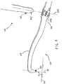
- FIG. 1 depicts an illustrative embodiment of a microfracture pick 100, in accordance with the subject application.
- the microfracture pick 100 has a proximal portion that includes an elongated handle 102, and a distal portion that includes a generally elongated shaft 104, which has a proximal end 110 and a distal end 112.
- the handle 102 is coupled to the proximal end 110 of the shaft 104.
- the microfracture pick 100 further includes a sharp, optionally angled tip 106 located at the distal end 112 of the shaft 104, and an engaging feature 108 disposed at a fixed location on the shaft 104 for engaging a complementary feature 114 of a strike instrument 101.
- the strike instrument 101 can include a shaft 116 that has a proximal end 118 and a distal end 120, and the complementary feature 114 can be located at the distal end 120 of the shaft 116.
- the strike instrument 101 can further include a handle 122 having a proximal end 124 and a distal end 126 coupled to the proximal end 118 of the shaft 116, and an impact surface 128 located at the proximal end 124 of the handle 122.
- the handle 122, the shaft 116, and the impact surface 128 of the strike instrument 101 can be implemented as a single component.
- the handle 102 and the shaft 104 of the microfracture pick 100 can be implemented as a single component.
- the shaft 104 of the microfracture pick 100, as well as the shaft 116 of the strike instrument 101 can be made from machined medical grade material such as hardened stainless steel, or any other suitable material.
- the handle 102 of the microfracture pick 100, as well as the handle 122 of the strike instrument 101 can have a cylindrical shape, or any other suitable shape. In some embodiments, the handle 102 of the microfracture pick 100 may be omitted.
- the tip 106 can be optionally bent at an angle of about 20°, 40°, 60°, 90°, or any other suitable angle, relative to the longitudinal axis 142 of the microfracture pick 100.
- the tip 106 can be optionally bent at an angle greater than 90° relative to the longitudinal axis 142 by bending the tip 106 back toward the handle 102.
- the direction 133 of the sharp tip 106 of the microfracture pick 100 can be aligned at an angle ⁇ relative to a surface 130 (see FIG. 1 ), which can correspond to the surface of bone.
- a surface 130 see FIG. 1
- the longitudinal axis 132 the strike instrument 101 can be aligned at about the same angle ⁇ relative to the surface 130.
- a force 134 is produced that is translated via the shaft 104 of the microfracture pick 100 through the tip 106.
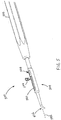
- FIG. 2 depicts a perspective view of the microfracture pick 100, including the handle 102, the shaft 104, the sharp, optionally angled tip 106, and the engaging feature (see reference numeral 108; FIG. 1 ), which is configured as a receptacle 208.
- the complementary feature 114 of the strike instrument 101 (see FIG. 1 ) is configured to operatively engage the receptacle 208 of the microfracture pick 100. To assure that the strike instrument 101 is aligned at about the same angle ⁇ as the tip 106 relative to the surface 130 (see FIG.
- the receptacle 208 can be configured such that its axis 232 is substantially parallel to the direction 133 of the tip 106. Accordingly, if the surgeon experiences difficulties advancing the tip 106 of microfracture pick 100 through bone, he or she can insert the complementary feature 114 of the strike instrument 101 into the receptacle 208 of the microfracture pick 100, and strike the impact surface 128 of the strike instrument 101 one or more times with a hammer or mallet to produce a force along the axis 232 of the receptacle 208, thereby facilitating advancement of the tip 106 through the bone.
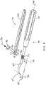
- FIG. 3 depicts a perspective view illustrating the microfracture pick 100 and the strike instrument 101, in which the complementary feature (see reference numeral 114; FIG. 1 ) is configured to include an optional nub 317 that can be temporarily or permanently fixated to the receptacle 208 of the microfracture pick 100.
- the optional nub 317, or an end of the shaft 116 without the nub 317 can be temporarily or permanently fixated to the receptacle 208 by way of threading, a press fit, a lever lock, a cam lock, a snap fit, a set screw, a taper fit, a luer lock (with or without taper), or any other suitable mechanism.
- FIG. 4 depicts a sectional view illustrating the microfracture pick 100 including the receptacle 208, as well as the strike instrument 101 including the optional nub 317.
- the receptacle 208 is illustrated as being substantially internal to the shaft 104 of the microfracture pick 100.
- the receptacle 208 can be configured such that its axis 232 is substantially parallel to the direction 133 of the tip 106.
- the nub 317 can be configured as a male connector or any other suitable connector
- the receptacle 208 can be configured as a female connector or any other suitable connector
- the microfracture pick 100 can be configured to include a male connector
- the strike instrument 101 can be configured to include a female connector for engaging the male connector of the microfracture pick 100.
- Such male and female connectors can be temporarily or permanently fixated to one another by way of threading, a press fit, a lever lock, a cam lock, a snap fit, a set screw, a taper fit, a luer lock (with or without taper), or any other suitable mechanism.
- the receptacle 208 can be configured to include an external drain hole 409 for sterilization and/or dry time purposes, as well as for avoiding a possible build-up of fluid in the receptacle 208 during use.
- the external drain hole 409 can have a diameter of about 2 mm, or any other suitable diameter.
- FIG. 5 depicts an alternative embodiment of a microfracture pick 500 that includes a handle 502, a shaft 504, a sharp, optionally angled tip 506, and an engaging feature 508.
- the shaft 504 is configured to incorporate a channel 540 along at least a portion of its length
- the engaging feature 508 is configured to engage and slide along the channel 540 to a desired location on the shaft 504.
- the channel 540 is substantially parallel to the longitudinal axis 542 of the shaft 504.
- the engaging feature 508 can be configured to include a receptacle like the receptacle 208 of FIG. 2 .
- the engaging feature 508 can be temporarily or permanently fixated at that location on the shaft 504 by at least one stop member 544, which, as shown in FIG. 5 , can be inserted into or otherwise engaged with the channel 540 adjacent the engaging feature 508, or by any other suitable mechanism.
- the engaging feature 508 can be temporarily or permanently fixated at a desired location on the shaft 504.
- the engaging feature 508 can be removed if it is not required to perform the microfracture procedure.
- FIG. 6 depicts another alternative embodiment of a microfracture pick 600 that includes a handle 602, a shaft 604, a sharp, optionally angled tip 606, and a plurality of engaging features 608.1, 608.2, 608.3 disposed at a plurality of fixed locations, respectively, on the shaft 604.
- FIG. 6 depicts three (3) such engaging features on the shaft 604 for purposes of illustration.
- the microfracture pick 600 can include any suitable number of engaging features disposed at respective locations on the shaft 604.
- each of the plurality of engaging features 608.1, 608.2, 608.3 can be configured to include a receptacle like the receptacle 208 of FIG. 2 .
- a strike instrument 601 in which the complementary feature is configured to include an optional nub 617 at an end of a shaft 616 that can be temporarily or permanently fixated to a selected one of the plurality of engaging features 608.1, 608.2, 608.3 on the shaft 604.
- the optional nub 617, or the end of the shaft 616 without the nub 617 can be temporarily or permanently fixated to the selected engaging feature 608.1, 608.2, or 608.3 by way of threading, a press fit, a lever lock, a cam lock, a snap fit, a set screw, a taper fit, a luer lock (with or without taper), or any other suitable mechanism.
- FIG. 7 depicts an alternative embodiment of a strike instrument 701, which includes a complementary feature 714 for engaging an engaging feature 708 of a microfracture pick 700.
- the strike instrument 701 includes a handle 722 having a proximal end 711, a distal end 713, and a hole 719 located near the distal end 713 of the handle 722.
- the strike instrument 701 further includes a strike pin 715 configured to pass snugly through the hole 719, the complementary feature 714 located at one end of the strike pin 715, and an impact surface 728 located at the other end of the strike pin 715.
- the handle 722, the strike pin 715, and the impact surface 728 of the strike instrument 701 can be implemented as a single component.
- the microfracture pick 700 includes a handle 702, a shaft 704, the engaging feature 708 located on the shaft 704, and a sharp, optionally angled tip 706 located at a distal end of the shaft 704. It is noted that the strike pin 715 can be temporarily or permanently fixated in the hole 719 through the handle 722 of the strike instrument 701.
- FIG. 8 depicts the microfracture pick 700 and the strike instrument 701, in which the complementary feature 714 of the strike instrument 701 is configured to include an optional nub 717, and the engaging feature 708 of the microfracture pick 700 is configured to include a receptacle 709.
- the optional nub 717, or an end of the strike pin 715 without the nub 717 can be temporarily or permanently fixated to the receptacle 709 of the microfracture pick 700 by way of threading, a press fit, a lever lock, a cam lock, a snap fit, a set screw, a taper fit, a luer lock (with or without taper), or any other suitable mechanism.
- the handle 722 of the strike instrument 701 can be temporarily or permanently fixated to the handle 702 of the microfracture pick 700 substantially parallel to its longitudinal axis 742, thereby allowing the surgeon to hold both the handle 722 of the strike instrument 701 and the handle 702 of the microfracture pick 700 with the same hand.
- the handle 722 of the strike instrument 701 can be temporarily or permanently fixated to the handle 702 of the microfracture pick 700 by way of threading, a press fit, a lever lock, a cam lock, a snap fit, a set screw, a taper fit, a luer lock (with or without taper), a bayonet mount, or any other suitable mechanism.
- the strike pin 715 can pass through the hole 719 in the handle 722 to engage the nub 717 of the strike instrument 701 with the receptacle 709 of the microfracture pick 700.
- the receptacle 709 can be configured such that its axis 732 is substantially parallel to the direction 733 of the tip 706.
- the surgeon can strike the impact surface 728 of the strike pin 715 one or more times with a hammer or mallet to produce a force 734 along the axis 732 of the receptacle 709, thereby facilitating advancement of the tip 706 through the bone.
- the microfracture pick could include a receptacle on its shaft
- the strike instrument could include an optional nub on its shaft for engaging the receptacle.
- the microfracture pick can include at least one engaging feature configured like a nub at a fixed or movable location on its shaft
- the strike instrument can include at least one complementary feature configured like a receptacle on its shaft.
- such a receptacle on the shaft of the strike instrument can have a forked configuration for cradling the nub on the shaft of the microfracture pick.
- the microfracture pick can alternatively include a nub or receptacle, such as a male or female connector, on its handle for engaging a complementary feature on the strike instrument.
- the strike instrument can alternatively include a nub or receptacle, such as a male or female connector, on its handle for complementarily engaging an engaging feature on the microfracture pick.
- the microfracture pick could include a plurality of engaging features disposed at respective locations on its shaft for engaging a complementary feature of the strike instrument.
- the plurality of engaging features of the microfracture pick can be configured as respective receptacles having parallel or non-parallel axes.
- the plurality of engaging features of the microfracture pick can each be configured to accept a different configuration of the complementary feature of the strike instrument.
- the method includes providing a microfracture pick having a shaft with a proximal end and a distal end, an optionally angled tip disposed at the distal end of the shaft, a handle coupled to the proximal end of the shaft, and at least one engaging feature disposed at one or more locations on the shaft for engaging a complementary feature of a strike instrument.
- the tip is located at a desired point of stimulation.
- At least a portion of the shaft may be inserted into an arthroscopic cannula.
- an impact surface of the strike instrument is struck by a hammer or mallet in a direction generally parallel to the direction of the tip to produce a force that is translated via the shaft through the tip at the desired point of stimulation.
- the tip is then removed from the desired point of stimulation.
- microfracture pick have been described for use in the context of resurfacing cartilage surfaces, they can also be used for perforating the subchondral bone in the subtalar/talus space (ankle) in arthrodesis procedures.
- a surgeon typically removes the cartilage on both the subtalar bone and the talus bone, and uses the microfracture pick to perforate the subtalar and talus bones in multiple places to promote bleeding.
- a screw is then delivered between the subtalar and talus bones to fuse the two bones together.
Landscapes
- Health & Medical Sciences (AREA)
- Surgery (AREA)
- Life Sciences & Earth Sciences (AREA)
- Biomedical Technology (AREA)
- Medical Informatics (AREA)
- Orthopedic Medicine & Surgery (AREA)
- Oral & Maxillofacial Surgery (AREA)
- Engineering & Computer Science (AREA)
- Dentistry (AREA)
- Heart & Thoracic Surgery (AREA)
- Nuclear Medicine, Radiotherapy & Molecular Imaging (AREA)
- Molecular Biology (AREA)
- Animal Behavior & Ethology (AREA)
- General Health & Medical Sciences (AREA)
- Public Health (AREA)
- Veterinary Medicine (AREA)
- Surgical Instruments (AREA)
- Prostheses (AREA)
Claims (14)
- Un dispositif chirurgical (100, 500, 600, 700) pour une utilisation dans la réalisation d'une procédure de microfracture, comprenant :un élément allongé (104, 504, 604, 704) ayant une extrémité proximale (110) et une extrémité distale (112) ;une pointe angulaire (106, 506, 606, 706) disposée de manière adjacente à l'extrémité distale de l'élément allongé ; etau moins un attribut de mise en prise (108, 508, 608.1, 608.2, 608.3, 708) disposé au niveau d'un ou de plusieurs emplacements sur l'élément allongé pour se mettre en prise avec un attribut complémentaire (114, 714) d'un instrument de frappe (101, 701), moyennant quoi, au moment où l'on frappe une surface d'impact (728) de l'instrument de frappe dans une direction généralement parallèle à une direction de la pointe, une force est produite qui est translatée via l'élément allongé à travers la pointe ; etdans lequel l'attribut de mise en prise est configuré sous la forme d'un attribut parmi un raccord femelle et un raccord mâle.
- Le dispositif chirurgical de la revendication 1 dans lequel l'attribut de mise en prise est configuré sous la forme d'un réceptacle (208).
- Le dispositif chirurgical de la revendication 2 dans lequel le réceptacle a un axe qui est généralement parallèle à la direction de la pointe.
- Le dispositif chirurgical de la revendication 2 ou de la revendication 3 dans lequel le réceptacle a un trou de drainage externe (409).
- Le dispositif chirurgical de la revendication 1 dans lequel l'élément allongé inclut un canal (540) dans au moins une portion de sa longueur, et l'attribut de mise en prise est configuré pour se mettre en prise et glisser dans le canal jusqu'à un emplacement souhaité sur l'élément allongé.
- Le dispositif chirurgical de la revendication 5 comprenant en outre :
au moins un élément d'arrêt opérationnel pour fixer l'attribut de mise en prise à l'emplacement souhaité sur l'élément allongé. - Le dispositif chirurgical de la revendication 1 comprenant en outre :
une pluralité d'attributs de mise en prise disposés à des emplacements respectifs sur l'élément allongé, chaque attribut de mise en prise étant destiné à se mettre en prise avec l'attribut complémentaire de l'instrument de frappe. - Le dispositif chirurgical de la revendication 7 dans lequel au moins certains des attributs de mise en prise ont des axes parallèles.
- Le dispositif chirurgical de la revendication 7 dans lequel au moins certains des attributs de mise en prise ont des axes non parallèles.
- Le dispositif chirurgical de la revendication 7 dans lequel au moins certains des attributs de mise en prise sont configurés pour se mettre en prise avec différentes configurations de l'attribut complémentaire de l'instrument de frappe.
- Un système pour une utilisation dans la réalisation d'une procédure de microfracture, comprenant :un instrument de frappe (701) incluant un élément allongé ayant une extrémité proximale, une extrémité distale, et un trou (719) dans l'élément allongé près de son extrémité distale, une tige de frappe (715) configurée pour passer à travers le trou dans l'élément allongé, et une surface d'impact placée à une extrémité de la tige de frappe ; etun dispositif chirurgical (700) selon n'importe quelle revendication précédente,dans lequel l'instrument de frappe inclut en outre un attribut complémentaire placé à une autre extrémité de la tige de frappe,dans lequel l'attribut de mise en prise du dispositif chirurgical est opérationnel pour se mettre en prise avec l'attribut complémentaire de l'instrument de frappe, etdans lequel l'élément allongé de l'instrument de frappe est configuré pour être disposé de manière généralement parallèle à un axe longitudinal du dispositif chirurgical afin de permettre la mise en prise de l'attribut de mise en prise avec l'attribut complémentaire, moyennant quoi, au moment où l'on frappe la surface d'impact de l'instrument de frappe dans une direction généralement parallèle à une direction de la pointe du dispositif chirurgical, une force est produite qui est translatée via l'élément allongé du dispositif chirurgical à travers la pointe.
- Le système de la revendication 11 dans lequel l'élément allongé de l'instrument de frappe est configuré pour être au moins temporairement fixé au dispositif chirurgical.
- Le système de la revendication 11 dans lequel l'attribut de mise en prise du dispositif chirurgical est configuré sous la forme d'un raccord femelle, et l'attribut complémentaire de l'instrument de frappe est configuré sous la forme d'un raccord mâle.
- Le système de la revendication 11 dans lequel l'attribut de mise en prise du dispositif chirurgical est configuré sous la forme d'un raccord mâle, et l'attribut complémentaire de l'instrument de frappe est configuré sous la forme d'un raccord femelle.
Applications Claiming Priority (2)
| Application Number | Priority Date | Filing Date | Title |
|---|---|---|---|
| US201261591980P | 2012-01-29 | 2012-01-29 | |
| PCT/US2013/021400 WO2013112308A1 (fr) | 2012-01-29 | 2013-01-14 | Pointe pour microfracture |
Publications (2)
| Publication Number | Publication Date |
|---|---|
| EP2806806A1 EP2806806A1 (fr) | 2014-12-03 |
| EP2806806B1 true EP2806806B1 (fr) | 2019-04-10 |
Family
ID=47664420
Family Applications (1)
| Application Number | Title | Priority Date | Filing Date |
|---|---|---|---|
| EP13702679.5A Active EP2806806B1 (fr) | 2012-01-29 | 2013-01-14 | Pointe pour microfracture |
Country Status (9)
| Country | Link |
|---|---|
| EP (1) | EP2806806B1 (fr) |
| JP (1) | JP6571334B2 (fr) |
| CN (1) | CN104379072B (fr) |
| AU (1) | AU2013212648B2 (fr) |
| BR (1) | BR112014018644A2 (fr) |
| CA (1) | CA2862947A1 (fr) |
| IN (1) | IN2014DN06756A (fr) |
| RU (1) | RU2014133463A (fr) |
| WO (1) | WO2013112308A1 (fr) |
Families Citing this family (7)
| Publication number | Priority date | Publication date | Assignee | Title |
|---|---|---|---|---|
| AU2014237438B2 (en) * | 2012-01-29 | 2018-11-29 | Smith & Nephew, Inc. | Microfracture pick |
| US9237894B2 (en) * | 2013-01-31 | 2016-01-19 | Depuy Mitek, Llc | Methods and devices for forming holes in bone to stimulate bone growth |
| WO2015179646A1 (fr) | 2014-05-21 | 2015-11-26 | The Uab Research Foundation | Alênes articulées de microfracture |
| KR101825270B1 (ko) * | 2015-10-26 | 2018-02-02 | 아주대학교산학협력단 | 미세골절술용 천공기구 |
| US10843325B2 (en) | 2017-03-08 | 2020-11-24 | DePuy Synthes Products, Inc. | Quick coupling apparatus on instrument handle |
| CN112826565A (zh) * | 2020-12-31 | 2021-05-25 | 青岛市市立医院 | 一种穿透更有效的微骨折镐 |
| CN115300039A (zh) * | 2022-08-19 | 2022-11-08 | 浙江天松医疗器械股份有限公司 | 一种微骨折器 |
Family Cites Families (7)
| Publication number | Priority date | Publication date | Assignee | Title |
|---|---|---|---|---|
| US4979574A (en) * | 1985-09-30 | 1990-12-25 | Lalama Craig R | Punch tool apparatus and method |
| WO1994026176A1 (fr) * | 1993-05-15 | 1994-11-24 | Ueth & Haug Gmbh | Dispositif de retrait d'endoprotheses |
| US6764491B2 (en) * | 1999-10-21 | 2004-07-20 | Sdgi Holdings, Inc. | Devices and techniques for a posterior lateral disc space approach |
| US6960214B2 (en) * | 2002-10-15 | 2005-11-01 | Zimmer Austin, Inc. | Method for performing automated microfracture |
| JP5154537B2 (ja) * | 2006-03-15 | 2013-02-27 | スミス アンド ネフュー インコーポレーテッド | 微小破壊ピック |
| US20100191195A1 (en) * | 2006-10-08 | 2010-07-29 | Ira Kirschenbaum | Cannulated apparatus and method relating to microfracture and revascularization methodologies |
| WO2009129272A2 (fr) * | 2008-04-15 | 2009-10-22 | Lonnie Paulos | Appareil pour microfractures tissulaires et ses méthodes d'utilisation |
-
2013
- 2013-01-14 EP EP13702679.5A patent/EP2806806B1/fr active Active
- 2013-01-14 CA CA2862947A patent/CA2862947A1/fr not_active Abandoned
- 2013-01-14 CN CN201380017723.6A patent/CN104379072B/zh active Active
- 2013-01-14 AU AU2013212648A patent/AU2013212648B2/en active Active
- 2013-01-14 JP JP2014554735A patent/JP6571334B2/ja active Active
- 2013-01-14 IN IN6756DEN2014 patent/IN2014DN06756A/en unknown
- 2013-01-14 RU RU2014133463A patent/RU2014133463A/ru not_active Application Discontinuation
- 2013-01-14 BR BR112014018644A patent/BR112014018644A2/pt not_active IP Right Cessation
- 2013-01-14 WO PCT/US2013/021400 patent/WO2013112308A1/fr active Application Filing
Non-Patent Citations (1)
| Title |
|---|
| None * |
Also Published As
| Publication number | Publication date |
|---|---|
| BR112014018644A2 (pt) | 2017-07-04 |
| AU2013212648A1 (en) | 2014-08-21 |
| CN104379072B (zh) | 2017-07-14 |
| EP2806806A1 (fr) | 2014-12-03 |
| RU2014133463A (ru) | 2016-03-20 |
| IN2014DN06756A (fr) | 2015-05-22 |
| WO2013112308A1 (fr) | 2013-08-01 |
| CN104379072A (zh) | 2015-02-25 |
| JP2015505484A (ja) | 2015-02-23 |
| JP6571334B2 (ja) | 2019-09-04 |
| CA2862947A1 (fr) | 2013-08-01 |
| AU2013212648B2 (en) | 2017-06-15 |
Similar Documents
| Publication | Publication Date | Title |
|---|---|---|
| US9259230B2 (en) | Microfracture pick | |
| EP2806806B1 (fr) | Pointe pour microfracture | |
| US9895179B2 (en) | Intramedullary fixation devices | |
| US8409250B2 (en) | Meniscal repair system and method | |
| US7942881B2 (en) | Microfracture pick | |
| US7837713B2 (en) | Methods and surgical kits for minimally-invasive facet joint fusion | |
| DK2987458T3 (en) | Microfracture equipment | |
| US9655630B2 (en) | Methods and devices for forming holes in bone to stimulate bone growth | |
| JP2019063582A (ja) | マイクロフラクチャーピック |
Legal Events
| Date | Code | Title | Description |
|---|---|---|---|
| PUAI | Public reference made under article 153(3) epc to a published international application that has entered the european phase |
Free format text: ORIGINAL CODE: 0009012 |
|
| 17P | Request for examination filed |
Effective date: 20140829 |
|
| AK | Designated contracting states |
Kind code of ref document: A1 Designated state(s): AL AT BE BG CH CY CZ DE DK EE ES FI FR GB GR HR HU IE IS IT LI LT LU LV MC MK MT NL NO PL PT RO RS SE SI SK SM TR |
|
| DAX | Request for extension of the european patent (deleted) | ||
| STAA | Information on the status of an ep patent application or granted ep patent |
Free format text: STATUS: EXAMINATION IS IN PROGRESS |
|
| 17Q | First examination report despatched |
Effective date: 20170308 |
|
| RAP1 | Party data changed (applicant data changed or rights of an application transferred) |
Owner name: SMITH & NEPHEW, INC |
|
| GRAP | Despatch of communication of intention to grant a patent |
Free format text: ORIGINAL CODE: EPIDOSNIGR1 |
|
| STAA | Information on the status of an ep patent application or granted ep patent |
Free format text: STATUS: GRANT OF PATENT IS INTENDED |
|
| INTG | Intention to grant announced |
Effective date: 20181026 |
|
| GRAS | Grant fee paid |
Free format text: ORIGINAL CODE: EPIDOSNIGR3 |
|
| GRAA | (expected) grant |
Free format text: ORIGINAL CODE: 0009210 |
|
| STAA | Information on the status of an ep patent application or granted ep patent |
Free format text: STATUS: THE PATENT HAS BEEN GRANTED |
|
| AK | Designated contracting states |
Kind code of ref document: B1 Designated state(s): AL AT BE BG CH CY CZ DE DK EE ES FI FR GB GR HR HU IE IS IT LI LT LU LV MC MK MT NL NO PL PT RO RS SE SI SK SM TR |
|
| REG | Reference to a national code |
Ref country code: GB Ref legal event code: FG4D |
|
| REG | Reference to a national code |
Ref country code: CH Ref legal event code: EP Ref country code: AT Ref legal event code: REF Ref document number: 1117614 Country of ref document: AT Kind code of ref document: T Effective date: 20190415 |
|
| REG | Reference to a national code |
Ref country code: IE Ref legal event code: FG4D |
|
| REG | Reference to a national code |
Ref country code: DE Ref legal event code: R096 Ref document number: 602013053610 Country of ref document: DE |
|
| REG | Reference to a national code |
Ref country code: NL Ref legal event code: MP Effective date: 20190410 |
|
| REG | Reference to a national code |
Ref country code: LT Ref legal event code: MG4D |
|
| REG | Reference to a national code |
Ref country code: AT Ref legal event code: MK05 Ref document number: 1117614 Country of ref document: AT Kind code of ref document: T Effective date: 20190410 |
|
| PG25 | Lapsed in a contracting state [announced via postgrant information from national office to epo] |
Ref country code: NL Free format text: LAPSE BECAUSE OF FAILURE TO SUBMIT A TRANSLATION OF THE DESCRIPTION OR TO PAY THE FEE WITHIN THE PRESCRIBED TIME-LIMIT Effective date: 20190410 |
|
| PG25 | Lapsed in a contracting state [announced via postgrant information from national office to epo] |
Ref country code: SE Free format text: LAPSE BECAUSE OF FAILURE TO SUBMIT A TRANSLATION OF THE DESCRIPTION OR TO PAY THE FEE WITHIN THE PRESCRIBED TIME-LIMIT Effective date: 20190410 Ref country code: AL Free format text: LAPSE BECAUSE OF FAILURE TO SUBMIT A TRANSLATION OF THE DESCRIPTION OR TO PAY THE FEE WITHIN THE PRESCRIBED TIME-LIMIT Effective date: 20190410 Ref country code: PT Free format text: LAPSE BECAUSE OF FAILURE TO SUBMIT A TRANSLATION OF THE DESCRIPTION OR TO PAY THE FEE WITHIN THE PRESCRIBED TIME-LIMIT Effective date: 20190910 Ref country code: FI Free format text: LAPSE BECAUSE OF FAILURE TO SUBMIT A TRANSLATION OF THE DESCRIPTION OR TO PAY THE FEE WITHIN THE PRESCRIBED TIME-LIMIT Effective date: 20190410 Ref country code: NO Free format text: LAPSE BECAUSE OF FAILURE TO SUBMIT A TRANSLATION OF THE DESCRIPTION OR TO PAY THE FEE WITHIN THE PRESCRIBED TIME-LIMIT Effective date: 20190710 Ref country code: LT Free format text: LAPSE BECAUSE OF FAILURE TO SUBMIT A TRANSLATION OF THE DESCRIPTION OR TO PAY THE FEE WITHIN THE PRESCRIBED TIME-LIMIT Effective date: 20190410 Ref country code: HR Free format text: LAPSE BECAUSE OF FAILURE TO SUBMIT A TRANSLATION OF THE DESCRIPTION OR TO PAY THE FEE WITHIN THE PRESCRIBED TIME-LIMIT Effective date: 20190410 Ref country code: ES Free format text: LAPSE BECAUSE OF FAILURE TO SUBMIT A TRANSLATION OF THE DESCRIPTION OR TO PAY THE FEE WITHIN THE PRESCRIBED TIME-LIMIT Effective date: 20190410 |
|
| PG25 | Lapsed in a contracting state [announced via postgrant information from national office to epo] |
Ref country code: GR Free format text: LAPSE BECAUSE OF FAILURE TO SUBMIT A TRANSLATION OF THE DESCRIPTION OR TO PAY THE FEE WITHIN THE PRESCRIBED TIME-LIMIT Effective date: 20190711 Ref country code: PL Free format text: LAPSE BECAUSE OF FAILURE TO SUBMIT A TRANSLATION OF THE DESCRIPTION OR TO PAY THE FEE WITHIN THE PRESCRIBED TIME-LIMIT Effective date: 20190410 Ref country code: RS Free format text: LAPSE BECAUSE OF FAILURE TO SUBMIT A TRANSLATION OF THE DESCRIPTION OR TO PAY THE FEE WITHIN THE PRESCRIBED TIME-LIMIT Effective date: 20190410 Ref country code: BG Free format text: LAPSE BECAUSE OF FAILURE TO SUBMIT A TRANSLATION OF THE DESCRIPTION OR TO PAY THE FEE WITHIN THE PRESCRIBED TIME-LIMIT Effective date: 20190710 Ref country code: LV Free format text: LAPSE BECAUSE OF FAILURE TO SUBMIT A TRANSLATION OF THE DESCRIPTION OR TO PAY THE FEE WITHIN THE PRESCRIBED TIME-LIMIT Effective date: 20190410 |
|
| PG25 | Lapsed in a contracting state [announced via postgrant information from national office to epo] |
Ref country code: IS Free format text: LAPSE BECAUSE OF FAILURE TO SUBMIT A TRANSLATION OF THE DESCRIPTION OR TO PAY THE FEE WITHIN THE PRESCRIBED TIME-LIMIT Effective date: 20190810 Ref country code: AT Free format text: LAPSE BECAUSE OF FAILURE TO SUBMIT A TRANSLATION OF THE DESCRIPTION OR TO PAY THE FEE WITHIN THE PRESCRIBED TIME-LIMIT Effective date: 20190410 |
|
| REG | Reference to a national code |
Ref country code: DE Ref legal event code: R097 Ref document number: 602013053610 Country of ref document: DE |
|
| PG25 | Lapsed in a contracting state [announced via postgrant information from national office to epo] |
Ref country code: DK Free format text: LAPSE BECAUSE OF FAILURE TO SUBMIT A TRANSLATION OF THE DESCRIPTION OR TO PAY THE FEE WITHIN THE PRESCRIBED TIME-LIMIT Effective date: 20190410 Ref country code: EE Free format text: LAPSE BECAUSE OF FAILURE TO SUBMIT A TRANSLATION OF THE DESCRIPTION OR TO PAY THE FEE WITHIN THE PRESCRIBED TIME-LIMIT Effective date: 20190410 Ref country code: CZ Free format text: LAPSE BECAUSE OF FAILURE TO SUBMIT A TRANSLATION OF THE DESCRIPTION OR TO PAY THE FEE WITHIN THE PRESCRIBED TIME-LIMIT Effective date: 20190410 Ref country code: RO Free format text: LAPSE BECAUSE OF FAILURE TO SUBMIT A TRANSLATION OF THE DESCRIPTION OR TO PAY THE FEE WITHIN THE PRESCRIBED TIME-LIMIT Effective date: 20190410 Ref country code: SK Free format text: LAPSE BECAUSE OF FAILURE TO SUBMIT A TRANSLATION OF THE DESCRIPTION OR TO PAY THE FEE WITHIN THE PRESCRIBED TIME-LIMIT Effective date: 20190410 |
|
| PLBE | No opposition filed within time limit |
Free format text: ORIGINAL CODE: 0009261 |
|
| STAA | Information on the status of an ep patent application or granted ep patent |
Free format text: STATUS: NO OPPOSITION FILED WITHIN TIME LIMIT |
|
| PG25 | Lapsed in a contracting state [announced via postgrant information from national office to epo] |
Ref country code: SM Free format text: LAPSE BECAUSE OF FAILURE TO SUBMIT A TRANSLATION OF THE DESCRIPTION OR TO PAY THE FEE WITHIN THE PRESCRIBED TIME-LIMIT Effective date: 20190410 Ref country code: IT Free format text: LAPSE BECAUSE OF FAILURE TO SUBMIT A TRANSLATION OF THE DESCRIPTION OR TO PAY THE FEE WITHIN THE PRESCRIBED TIME-LIMIT Effective date: 20190410 |
|
| 26N | No opposition filed |
Effective date: 20200113 |
|
| PG25 | Lapsed in a contracting state [announced via postgrant information from national office to epo] |
Ref country code: TR Free format text: LAPSE BECAUSE OF FAILURE TO SUBMIT A TRANSLATION OF THE DESCRIPTION OR TO PAY THE FEE WITHIN THE PRESCRIBED TIME-LIMIT Effective date: 20190410 |
|
| PG25 | Lapsed in a contracting state [announced via postgrant information from national office to epo] |
Ref country code: SI Free format text: LAPSE BECAUSE OF FAILURE TO SUBMIT A TRANSLATION OF THE DESCRIPTION OR TO PAY THE FEE WITHIN THE PRESCRIBED TIME-LIMIT Effective date: 20190410 |
|
| PG25 | Lapsed in a contracting state [announced via postgrant information from national office to epo] |
Ref country code: MC Free format text: LAPSE BECAUSE OF FAILURE TO SUBMIT A TRANSLATION OF THE DESCRIPTION OR TO PAY THE FEE WITHIN THE PRESCRIBED TIME-LIMIT Effective date: 20190410 |
|
| REG | Reference to a national code |
Ref country code: CH Ref legal event code: PL |
|
| REG | Reference to a national code |
Ref country code: BE Ref legal event code: MM Effective date: 20200131 |
|
| PG25 | Lapsed in a contracting state [announced via postgrant information from national office to epo] |
Ref country code: LU Free format text: LAPSE BECAUSE OF NON-PAYMENT OF DUE FEES Effective date: 20200114 |
|
| PG25 | Lapsed in a contracting state [announced via postgrant information from national office to epo] |
Ref country code: LI Free format text: LAPSE BECAUSE OF NON-PAYMENT OF DUE FEES Effective date: 20200131 Ref country code: CH Free format text: LAPSE BECAUSE OF NON-PAYMENT OF DUE FEES Effective date: 20200131 Ref country code: BE Free format text: LAPSE BECAUSE OF NON-PAYMENT OF DUE FEES Effective date: 20200131 |
|
| PG25 | Lapsed in a contracting state [announced via postgrant information from national office to epo] |
Ref country code: IE Free format text: LAPSE BECAUSE OF NON-PAYMENT OF DUE FEES Effective date: 20200114 |
|
| PG25 | Lapsed in a contracting state [announced via postgrant information from national office to epo] |
Ref country code: MT Free format text: LAPSE BECAUSE OF FAILURE TO SUBMIT A TRANSLATION OF THE DESCRIPTION OR TO PAY THE FEE WITHIN THE PRESCRIBED TIME-LIMIT Effective date: 20190410 Ref country code: CY Free format text: LAPSE BECAUSE OF FAILURE TO SUBMIT A TRANSLATION OF THE DESCRIPTION OR TO PAY THE FEE WITHIN THE PRESCRIBED TIME-LIMIT Effective date: 20190410 |
|
| PG25 | Lapsed in a contracting state [announced via postgrant information from national office to epo] |
Ref country code: MK Free format text: LAPSE BECAUSE OF FAILURE TO SUBMIT A TRANSLATION OF THE DESCRIPTION OR TO PAY THE FEE WITHIN THE PRESCRIBED TIME-LIMIT Effective date: 20190410 |
|
| P01 | Opt-out of the competence of the unified patent court (upc) registered |
Effective date: 20230525 |
|
| PGFP | Annual fee paid to national office [announced via postgrant information from national office to epo] |
Ref country code: GB Payment date: 20231221 Year of fee payment: 12 |
|
| PGFP | Annual fee paid to national office [announced via postgrant information from national office to epo] |
Ref country code: FR Payment date: 20231222 Year of fee payment: 12 |
|
| PGFP | Annual fee paid to national office [announced via postgrant information from national office to epo] |
Ref country code: DE Payment date: 20231220 Year of fee payment: 12 |