EP2806805B1 - Appareil de réparation de valvule cardiaque - Google Patents
Appareil de réparation de valvule cardiaque Download PDFInfo
- Publication number
- EP2806805B1 EP2806805B1 EP13705856.6A EP13705856A EP2806805B1 EP 2806805 B1 EP2806805 B1 EP 2806805B1 EP 13705856 A EP13705856 A EP 13705856A EP 2806805 B1 EP2806805 B1 EP 2806805B1
- Authority
- EP
- European Patent Office
- Prior art keywords
- door
- tissue
- clip
- doors
- closed
- Prior art date
- Legal status (The legal status is an assumption and is not a legal conclusion. Google has not performed a legal analysis and makes no representation as to the accuracy of the status listed.)
- Not-in-force
Links
Images


Classifications
-
- A—HUMAN NECESSITIES
- A61—MEDICAL OR VETERINARY SCIENCE; HYGIENE
- A61B—DIAGNOSIS; SURGERY; IDENTIFICATION
- A61B17/00—Surgical instruments, devices or methods, e.g. tourniquets
- A61B17/12—Surgical instruments, devices or methods, e.g. tourniquets for ligaturing or otherwise compressing tubular parts of the body, e.g. blood vessels, umbilical cord
- A61B17/122—Clamps or clips, e.g. for the umbilical cord
- A61B17/1227—Spring clips
-
- A—HUMAN NECESSITIES
- A61—MEDICAL OR VETERINARY SCIENCE; HYGIENE
- A61B—DIAGNOSIS; SURGERY; IDENTIFICATION
- A61B17/00—Surgical instruments, devices or methods, e.g. tourniquets
- A61B17/064—Surgical staples, i.e. penetrating the tissue
- A61B17/0644—Surgical staples, i.e. penetrating the tissue penetrating the tissue, deformable to closed position
-
- A—HUMAN NECESSITIES
- A61—MEDICAL OR VETERINARY SCIENCE; HYGIENE
- A61B—DIAGNOSIS; SURGERY; IDENTIFICATION
- A61B17/00—Surgical instruments, devices or methods, e.g. tourniquets
- A61B17/068—Surgical staplers, e.g. containing multiple staples or clamps
-
- A—HUMAN NECESSITIES
- A61—MEDICAL OR VETERINARY SCIENCE; HYGIENE
- A61B—DIAGNOSIS; SURGERY; IDENTIFICATION
- A61B17/00—Surgical instruments, devices or methods, e.g. tourniquets
- A61B17/12—Surgical instruments, devices or methods, e.g. tourniquets for ligaturing or otherwise compressing tubular parts of the body, e.g. blood vessels, umbilical cord
- A61B17/128—Surgical instruments, devices or methods, e.g. tourniquets for ligaturing or otherwise compressing tubular parts of the body, e.g. blood vessels, umbilical cord for applying or removing clamps or clips
- A61B17/1285—Surgical instruments, devices or methods, e.g. tourniquets for ligaturing or otherwise compressing tubular parts of the body, e.g. blood vessels, umbilical cord for applying or removing clamps or clips for minimally invasive surgery
-
- A—HUMAN NECESSITIES
- A61—MEDICAL OR VETERINARY SCIENCE; HYGIENE
- A61B—DIAGNOSIS; SURGERY; IDENTIFICATION
- A61B17/00—Surgical instruments, devices or methods, e.g. tourniquets
- A61B17/00234—Surgical instruments, devices or methods, e.g. tourniquets for minimally invasive surgery
- A61B2017/00238—Type of minimally invasive operation
- A61B2017/00243—Type of minimally invasive operation cardiac
-
- A—HUMAN NECESSITIES
- A61—MEDICAL OR VETERINARY SCIENCE; HYGIENE
- A61B—DIAGNOSIS; SURGERY; IDENTIFICATION
- A61B17/00—Surgical instruments, devices or methods, e.g. tourniquets
- A61B2017/00743—Type of operation; Specification of treatment sites
- A61B2017/00778—Operations on blood vessels
- A61B2017/00783—Valvuloplasty
-
- A—HUMAN NECESSITIES
- A61—MEDICAL OR VETERINARY SCIENCE; HYGIENE
- A61B—DIAGNOSIS; SURGERY; IDENTIFICATION
- A61B17/00—Surgical instruments, devices or methods, e.g. tourniquets
- A61B2017/00831—Material properties
- A61B2017/00867—Material properties shape memory effect
-
- A—HUMAN NECESSITIES
- A61—MEDICAL OR VETERINARY SCIENCE; HYGIENE
- A61B—DIAGNOSIS; SURGERY; IDENTIFICATION
- A61B17/00—Surgical instruments, devices or methods, e.g. tourniquets
- A61B17/064—Surgical staples, i.e. penetrating the tissue
- A61B2017/0641—Surgical staples, i.e. penetrating the tissue having at least three legs as part of one single body
-
- A—HUMAN NECESSITIES
- A61—MEDICAL OR VETERINARY SCIENCE; HYGIENE
- A61B—DIAGNOSIS; SURGERY; IDENTIFICATION
- A61B17/00—Surgical instruments, devices or methods, e.g. tourniquets
- A61B17/064—Surgical staples, i.e. penetrating the tissue
- A61B2017/0645—Surgical staples, i.e. penetrating the tissue being elastically deformed for insertion
-
- A—HUMAN NECESSITIES
- A61—MEDICAL OR VETERINARY SCIENCE; HYGIENE
- A61B—DIAGNOSIS; SURGERY; IDENTIFICATION
- A61B17/00—Surgical instruments, devices or methods, e.g. tourniquets
- A61B17/064—Surgical staples, i.e. penetrating the tissue
- A61B2017/0649—Coils or spirals
Definitions
- the present invention is related to tissue repair, and more particularly to devices and systems for minimally invasive repair of a heart valve leaflet.
- Properly functioning heart valves can maintain unidirectional blood flow in the circulatory system by opening and closing, depending on the difference in pressure from one side of the valve to the other.
- the two atrioventricular valves (mitral and tricuspid valves) are multicusped valves that prevent backflow from the ventricles into the atria during systole. They are anchored to the wall of the ventricle by chordae tendineae, which prevent the valve from inverting.
- the mitral valve is located at the gate of the left ventricle and is made up of two leaflets and a diaphanous incomplete ring around the valve, known as the mitral valve annulus.
- the mitral valve annulus When the valve opens, blood flows into the left ventricle. After the left ventricle fills with blood and contracts, the two leaflets of the mitral valve are pushed upwards and close, preventing blood from flowing back into the left atrium and the lungs.
- Mitral valve prolapse is a type of myxomatous valve disease in which the abnormal mitral valve leaflets prolapse (i.e., a portion of the affected leaflet may be billowed, loose, and floppy). Furthermore, the chordae tendineae may stretch and thus become too long, or the chordae tendineae may be ruptured. As a result, the valve is not properly held in a closed condition. As a result of being stretched, the unsupported valve leaflet bulges back, or "prolapses,” into the left atrium like a parachute. Thus, as the ventricle contracts, the abnormal leaflet may be propelled backwards, beyond its normal closure line into the left atrium, thereby allowing blood to return to the left atrium and the lungs.
- Mitral valve prolapse causes mitral regurgitation. Isolated posterior leaflet prolapse of the human heart mitral valve, i.e. prolapse of a single leaflet, is the most common cause of mitral regurgitation. The exact cause of the prolapse is not clear. Untreated mitral regurgitation may lead to congestive heart failure and pulmonary hypertension.
- WO 03/049619 discloses a grasping device having an inner lumen for advancing connecting members to secure heart valve leaflets. This document discloses the features of the preamble of claim 1.
- WO 99/00059 discloses an apparatus for repair of heart valve leaflets comprising a grasper with jaws to immobilize the leaflets and then insert a fastener.
- mitral valve leaflet repair Despite the various improvements that have been made to devices and methods for mitral valve leaflet repair, there remain some shortcomings.
- conventional methods of treating mitral valve prolapse include replacement of the mitral valve, clipping the two mitral valve leaflets to one another, and resection of the prolapsed segment using open heart surgery.
- Such surgical methods may be invasive to the patient and may require an extended recovery period.
- the present invention may address one or more of these needs.
- a method of gathering tissue in a patient may include inserting an elongated device into the patient to a position adjacent the tissue, the device including a capture assembly having a closed side and a door rotatable between an open condition and a closed condition, the closed side and the door in the closed condition collectively defining a tissue capturing compartment.
- the door may then be moved from the closed condition to the open condition and engaged against the tissue.
- the door may be closed against the tissue to capture a portion of the tissue inside the tissue capturing compartment, the captured tissue being formed into a gathered configuration.
- At least one clip from the capture assembly may be applied to the captured tissue so as to hold the captured tissue substantially in the gathered configuration.
- the tissue may be a heart valve leaflet.
- the capture assembly may include a spring element coupled to the door and biased to move the door to the closed condition.
- the door may include at least one prong projecting therefrom, and the closing step may include grasping the captured tissue with the at least one prong.
- the door may include a portion with serrations, and the closing step may include grasping the captured tissue with the serrations.
- the device may include a deployment element attached to the door and operable by a user, and the moving step may include pulling the deployment element to rotate the door to the open condition.
- the capture assembly may include first and second doors rotatable between open and closed conditions, and the closing step may include closing the first and second doors against the tissue to capture the portion of the tissue inside the tissue capturing compartment.
- the clip is biased to a substantially round condition and engaged with the door to hold the clip in an open condition, and the applying step may include releasing the clip from engagement with the door, whereby the clip may move from the open condition to the substantially round condition.
- the device may include an actuating rod movable relative to the at least one clip, and the applying step may include moving the actuating rod to contact the at least one clip and releasing the at least one clip for application to the captured tissue.
- a device for gathering tissue in a patient may include an elongated catheter having a proximal portion and a distal portion and a capture assembly at the distal portion of the catheter.
- the capture assembly may include a closed side and a door rotatable between an open condition and a closed condition, the closed side and the door in the closed condition collectively defining a tissue capturing compartment.
- the door may be operable to capture a portion of the tissue in a gathered configuration within the tissue capturing compartment.
- the device may also include a spring element coupled to the door and biased to move the door to the closed condition.
- the door may have one edge rotatably connected to the closed side of the capture assembly and a free edge opposite the one edge.
- the free edge may include at least one prong projecting therefrom.
- the free edge may include a plurality of serrations.
- the device may also include a deployment element attached to the door and extending through the elongated catheter.
- the capture assembly may include first and second doors rotatable between open and closed conditions. The first and second doors may be operable to capture the portion of the tissue in a gathered configuration within the tissue capturing compartment.
- the device may also include at least one clip releasably held in the tissue capturing compartment and adapted to be applied to the captured tissue for holding the captured tissue in the gathered configuration.
- the clip is biased to a substantially round condition and is engaged with the door to hold the clip in an open condition.
- the clip may have a first end and a second end, and the door may include a slot. The first end of the clip may be engaged in the slot. Movement of the door to the open condition may create a biasing force in the clip tending to move the door to the closed condition.
- the device may also include an actuating rod slidably disposed in the tissue capturing compartment.
- the actuating rod may have a laterally projecting bump, and the clip may be at least partially held in a travel path of the bump. Movement of the bump through the travel path may cause the bump to release the clip for application to the captured tissue.
- the bump may have an oval cross-section, and a portion of the actuating rod adjacent the bump may have a round cross-section that is smaller than the oval cross-section in at least one direction.
- proximal and distal are to be taken as relative to a user (e.g., a surgeon or an interventional cardiologist) using the disclosed devices.
- Proximal is to be understood as relatively close to the user and “distal” is to be understood as relatively farther away from the user.
- the invention will be described in connection with the repair of a mitral valve leaflet, but it may be useful in the repair of other types of cardiac valves or in the gathering and clamping of other types of loose body tissue.
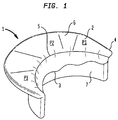
- an exemplary mitral valve 1 includes a posterior leaflet 2 and an anterior leaflet 3.
- the leaflets 2 and 3 extend from an annulus 4 to a coaption line 5 where the leaflets meet.
- the posterior leaflet 2 has an upper portion 6 that is generally perpendicular to the direction of blood flow through the valve 1 and extends between the annulus 4 and the coaption line 5. Additionally, the posterior leaflet 2 has a lower portion 7 that is generally parallel to the direction of blood flow through the valve 1 and extends below the coaption line 5.
- the posterior leaflet 2 has three scalloped portions P1, P2, and P3, any of which may include a portion that is billowed, loose, or floppy, and therefore be the cause of a prolapse condition of the valve.
- inventive devices, systems, and methods described herein may be adapted to repair such a billowed, loose, or floppy portion of the posterior leaflet 2 or the anterior leaflet 3.
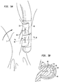
- Chordae tendineae 8 ( FIG. 3 ) may connect the lower portion 7 of the posterior leaflet 2 to the papillary muscles of the left ventricle 9.
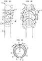
- an exemplary device 10 for gathering heart valve leaflet tissue includes an elongated catheter 14 adapted to be inserted through the apex of a human heart so that a capture assembly 13 at a distal portion of the catheter may reach the patient's mitral valve 1 for repair thereof.
- the capture assembly 13 preferably has an outer profile and cross-sectional shape similar to that of the catheter 14.
- the capture assembly 13 includes a proximal end wall 15, a distal end wall 16, a closed side 18 extending between the proximal and distal end walls, and a pair of hinged doors 20.
- An atraumatic tip 11 is positioned at the distal end of the capture assembly 13.
- the capture assembly 13 may be made of one or more echogenic materials so as to be more easily visualized inside a patient using three-dimensional echocardiography.
- Each door 20 is rotatably coupled to the closed side 18 at an inner longitudinal edge 28 of the door. As shown in FIGS. 2A-2C , each door 20 may be coupled to the closed side 18 by a hinge that includes a pin extending through apertures in the door and the closed side, but the invention contemplates any other coupling mechanism that allows the doors 20 to be rotatably coupled to the closed side, such as a living hinge.
- the doors 20 are rotatable relative to the closed side 18 of the capture assembly 13 between a closed condition shown in FIG. 2A and a fully open condition shown in FIG. 2B .
- a free longitudinal edge 32 of each door 20 may include prongs 30 adapted to engage with corresponding recesses 34 in the free longitudinal edge 32 of the opposite door when the doors are in the closed condition.
- a tissue capturing compartment 19 is defined between the doors and the closed side 18 of the capture assembly 13.
- the capture assembly 13 further includes one or more clips 40, the ends of which are engaged in corresponding slots 36 in the doors 20.
- the ends of each clip 40 may be formed with a prong 42 adapted to embed in the leaflet tissue when the clip is deployed.
- the clips 40 may be made of a memory metal and are biased to curl into a substantially round configuration. When the ends of the clips 40 are engaged in the slots 36, this biasing force biases the doors 20 to the closed condition.
- a deployment wire 50 for opening the doors 20 may extend through the catheter 14 from a proximal end connected to an actuating mechanism (not shown) located outside of the patient's body, and through the proximal end wall 15 of the capture assembly 13 into the tissue capturing compartment 19.
- the deployment wire 50 may then travel through a containment tube 58 positioned adjacent the inside surface of the closed side 18 of the capture assembly 13, and through an aperture 54 in the closed side to the exterior of the capture assembly.
- the distal end of the deployment wire 50 may have two arms 51 that wrap circumferentially around the outside of the closed side 18 of the capture assembly 13 and attach to the two doors 20 at attachment locations 52 near the free edge 32 of each door. As will be explained below, movement of the deployment wire 50 in the proximal direction moves the doors 20 from the closed condition to the open condition.
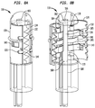
- An actuation rod 60 for releasing the clips 40 may extend through the catheter 14 from a proximal end connected to an actuating mechanism (not shown) located outside of the patient's body, and through an aperture 68 in the proximal end wall 15 of the capture assembly 13 into the tissue capturing compartment 19.
- the actuation rod 60 may be bent to define a bump 64 that curves laterally away from the longitudinal axis of the actuation rod.
- the actuation rod 60 is slidable between an initial position with its distal end 62 extending through an aperture 66 in the distal end wall 16 and into the atraumatic tip 11 ( FIG. 2B ), and a deployed position with its distal end located within the tissue capturing compartment 19.
- An example of a partially-deployed position of the actuation rod 60 is shown in FIG. 6 .
- the bump 64 is adapted to contact the clips 40 when the actuation rod 60 is slid proximally within the compartment 19.
- a user may first pull the deployment wire 50 proximally to open the doors 20.
- the clips 40 may then be loaded into the tissue capturing compartment 19 around the actuation rod 60, such that each clip is located between the actuation rod and the closed side 18 of the capture assembly 13, with the prongs 42 of each clip engaged in the corresponding slots 36 in the doors 20.
- the deployment wire 50 may be released, such that the biasing force exerted by the clips will pull the doors 20 into the closed condition.
- the device 10 may then be inserted into the patient and advanced until the capture assembly 13 is located adjacent the mitral valve, preferably using a transseptal approach. That is, the device 10 may be advanced from the femoral vein through the iliac vein, the inferior vena cava, and the right atrium, and across the septum wall into the left atrium, until the capture assembly 13 extends between the posterior leaflet 2 and the anterior leaflet 3 of the mitral valve 1, as shown in FIG. 3 .
- This route requires the least amount of bending or turning and provides the most direct route to the mitral valve leaflets. Minimizing the number of turns may facilitate the rotational control of the capture assembly 13. If the capture assembly 13 includes echogenic materials, it may be guided to a position against a leaflet near the coaption line 5 using the assistance of three-dimensional echocardiography.
- the user may pull the deployment wire 50 proximally to move the doors 20 to the fully open condition.
- the deployment wire 50 may be temporary locked relative to the closed side 18 of the capture assembly 13, for example, using a locking feature of a control handle (not shown) located at the proximal end of the catheter 14.
- the capture assembly 13 may be positioned adjacent the lower portion 7 of the posterior leaflet 2 so that the exposed tissue capturing compartment 19 faces the posterior leaflet. The capture assembly 13 may then be pressed against the lower portion 7 of the posterior leaflet 2 to engage the prongs 30 of the doors 20 in the tissue of the posterior leaflet.
- the user may release the deployment wire 50, so that the clips 40 are free to begin to curl into a substantially round configuration according to their bias, thereby closing the doors 20 against the tissue of the posterior leaflet 2 until the doors attain the partially open condition shown in FIGS. 5A and 5B .
- the prongs 30 in the longitudinal edges 32 of the doors may grasp and/or piece the leaflet tissue, pulling it toward the compartment 19.
- the doors 20 are in the partially open condition and engaged with the tissue of the posterior leaflet 2, some of the tissue of the posterior leaflet will be captured inside of the tissue capturing compartment 19 and within the diameter of the clips 40.
- This captured tissue 44 may form a pleat 46 extending substantially along the longitudinal axis of the tissue capturing compartment 19.
- the user may then release the clips 40 into engagement with the captured tissue 44 by sliding the actuation rod 60 proximally within the compartment 19.
- the bump 64 first contacts a distal clip 40a.
- the bump 64 provides a force in a lateral direction transverse to the longitudinal axis of the compartment 19, thereby forcing the distal clip 40a toward the closed side 18 of the compartment.
- the prongs 42 of the clip disengage from the slots 36. Only a small transverse movement of each clip 40 is required to disengage the prongs 42 from the corresponding slots 36.
- the clip 40a is disengaged from the slots 36, the clip is free to continue to curl into a substantially round configuration according to its bias, and the prongs 42 of the clip engage and may become embedded in the captured tissue 44 on either side of the pleat 46.
- the user may slide the actuation rod 60 further proximally, thereby disengaging a proximal clip 40b from the slots 36 and causing the prongs 42 of the proximal clip to engage and possibly embed in the captured tissue 44 in the same manner as the distal clip 40a.
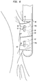
- the user may pull the deployment wire 50 proximally to move the doors 20 to a sufficiently open condition to allow the user to move the capture assembly 13 away from the posterior leaflet and disengage the prongs 30 of the doors 20 from the captured tissue 44.
- a memory feature may be included in the capture assembly 13 to provide a force according to its bias that tends to close the doors. Examples of such a memory feature may include a living hinge that couples the doors to the closed side 18 of the capture assembly 13 or a leaf spring 148, such as that shown in FIG. 8B . The procedure described above may be repeated to apply one or more additional clips 40 onto the same posterior leaflet 2.
- FIGS. 8A and 8B An alternative embodiment of a device 110 for gathering heart valve leaflet tissue is shown in FIGS. 8A and 8B .
- the device 110 is similar to the device 10 described above, but the device 110 includes alternate versions of the doors, the actuation rod, and the memory door-closing feature.
- the device 110 has doors 120 having a serrated edge 132.
- the serrated edges 132 of the doors 120 are adapted to become interleaved with one another when the doors are moved to the closed condition shown in FIG. 8A .
- the serrated edges 132 together define a longitudinal external recess 134 when the doors 120 are in the closed condition.
- the actuation rod 160 of the device 110 is similar in function to the actuation rod 60 described above.
- the actuation rod 160 has a generally oval cross-section along its entire length, with the exception of an elongated portion 165 spaced from the distal end 162 of the actuation rod that has a substantially round cross-section that is smaller than the oval cross-section in at least one direction.
- a bump 164 is defined on the distal end 162 of the actuation rod 160 that extends farther in a lateral direction from the longitudinal axis of the actuation rod than the elongated portion 165.
- the elongated portion 165 is disposed adjacent the clips 140.
- the bump 164 contacts the clips 140 and forces them toward the closed side 118 of the compartment 119, disengaging the clips from the slots 136.
- the aperture 166 at the distal end of the compartment 119 and the aperture 168 at the proximal end of the compartment have oval shapes that correspond to the oval shape of the actuation rod 160.
- the matching of these oval shapes prevents the actuation rod 160 from rotating, thereby keeping it oriented with the bump 164 facing toward the clips 140.
- the device 110 further includes a leaf spring 148 formed from a memory metal so as to be biased to the closed position shown in FIG. 8A .
- the ends of the leaf spring 148 are engaged in opposing slots 149 in the doors 120 so that the leaf spring provides a force according to its bias that tends to close the doors.
- the invention also contemplates the use of alternative structures for such purposes, including structures having different lengths, shapes, and configurations.
- a single rotatable door may be used.
- the door maybe rotatably coupled to a first longitudinal edge of the closed side of the capture assembly, the closed side and the door in the closed condition collectively defining the tissue capturing compartment.
- the single door may be closed against a second longitudinal edge of the closed side of the capture assembly to capture tissue of the heart valve leaflet inside the tissue capturing compartment.
- Other devices that have elements that rotate toward other rotatable or fixed structures to gather leaflet tissue into a fold or pleat onto which a clip may be applied are also contemplated herein.
- the devices have been described herein as including actuation rods with bumps that are moved proximally to displace the clips and release them for application to captured tissue
- the invention is not limited to such structures.
- the bump initially may be positioned adjacent the proximal end wall of the capture assembly, and the bump may be moved distally to displace the clips and release them for application to tissue captured in the tissue capturing compartment.
- the atraumatic tip of the device may have a through bore that accommodates the distal end of the actuation rod as it is moved distally.
- the distal end of the actuation rod may remain captured by the atraumatic tip throughout the entire travel motion of the rod, thereby minimizing any lateral deflection of the rod that may prevent the bump from displacing and releasing the clips during the clip deployment process.
- one or more bumps of the actuation rod may initially be positioned facing away from the closed side of the capture assembly, and the actuation rod may be rotated to bring the bump or bumps into contact with the clips to displace and release them for application to tissue captured in the tissue capturing compartment.
- the door-closing feature has been described above as a leaf spring, such as that shown in FIG. 8B
- any structure may be used to provide a force according to its bias that tends to close the doors.
- the doors and the closed side of the capture assembly may be constructed from a single contiguous piece of material, such as a memory metal or a strong, resilient metal or polymer, so as to provide a living hinge operable to bias the doors to the closed condition.
- a hinge such as that shown in FIG. 2C may include a coil spring disposed around the pin, the coil spring having an bias that tends to close the doors.
- the invention contemplates the application of only one clip or any number of clips greater than one to any leaflet tissue during a single insertion of the device into a patient.
- the tissue capturing compartment may be sufficiently long to accommodate any reasonable number of clips in side-by-side relationship in the longitudinal direction of the compartment, and all or less than all of the retained clips may be applied in a single procedure.
- all of the delivery devices may be used to repair other heart valve leaflets, such as the anterior leaflet of the mitral valve, or any other tissue of the body for which a reduction in the length of the tissue would be beneficial.
- the invention herein has been described with reference to particular embodiments in which the device is inserted into the patient and advanced to the mitral valve using a transseptal approach, it is to be understood that the invention contemplates embodiments in which the device reaches its target through another portion of the heart, such as the apex of the heart, through a portion of the vasculature of the patient, such as a subclavian artery, or through the aorta. In such embodiments, some of the device components may have to be oriented in a different direction than described herein. For example, the invention contemplates embodiments in which the capture assembly approaches the mitral valve from the downstream side as well as from the upstream side of the valve.
- the present invention enjoys wide industrial applicability including, but not limited to, devices for gathering tissue in a patient.
Claims (11)
- Dispositif (10 ; 110) pour recueillir du tissu chez un patient, le dispositif comprenant :un cathéter allongé (14) ayant une partie proximale et une partie distale ; etun ensemble de capture (13) au niveau de la partie distale du cathéter, l'ensemble de capture incluant un côté fermé et une trappe (20 ; 120) rotative entre un état ouvert et un état fermé, le côté fermé et la trappe dans l'état fermé définissant collectivement un compartiment de capture de tissu (19 ; 119),la trappe pouvant être mise en oeuvre pour capturer une partie du tissu dans une configuration recueillie à l'intérieur du compartiment de capture de tissu, etau moins une agrafe (40 ; 140) maintenue de façon amovible dans le compartiment de capture de tissu et conçue pour être appliquée au tissu capturé pour maintenir le tissu capturé dans la configuration recueillie,caractérisé par l'agrafe étant couplée à la trappe et sollicitée dans une configuration sensiblement arrondie pour déplacer la trappe vers l'état fermé.
- Dispositif selon la revendication 1, comprenant en outre un élément à ressort (148) couplé à la trappe et sollicité pour déplacer la trappe vers l'état fermé.
- Dispositif selon la revendication 1, dans lequel la trappe a un bord particulier (28) relié en rotation au côté fermé de l'ensemble de capture et un bord libre (32) opposé au bord particulier, le bord libre incluant au moins une dent (30) dépassant de ce dernier.
- Dispositif selon la revendication 1, dans lequel la trappe a un bord particulier relié en rotation au côté fermé de l'ensemble de capture et un bord libre opposé au bord particulier, le bord libre incluant une pluralité de dentelures (132).
- Dispositif selon la revendication 1, comprenant en outre un élément de déploiement (50) attaché à la trappe et s'étendant à travers le cathéter allongé.
- Dispositif selon la revendication 1, dans lequel l'ensemble de capture inclut des première et seconde trappes rotatives entre des états ouvert et fermé, les première et seconde trappes pouvant être mises en oeuvre pour capturer la partie du tissu dans une configuration recueillie à l'intérieur du compartiment de capture de tissu.
- Dispositif selon la revendication 1, dans lequel l'agrafe est sollicitée vers un état fermé et est en prise avec la trappe de sorte qu'un mouvement de la trappe vers l'état ouvert déplace l'agrafe vers un état ouvert.
- Dispositif selon la revendication 7, dans lequel l'agrafe a une première extrémité et une seconde extrémité, et la trappe inclut une fente (36 ; 136), la première extrémité de l'agrafe étant en prise dans la fente.
- Dispositif selon la revendication 8, dans lequel un mouvement de la trappe vers l'état ouvert crée une force de sollicitation dans l'agrafe ayant tendance à déplacer la trappe vers l'état fermé.
- Dispositif selon la revendication 1, comprenant en outre une tige d'actionnement (60 ; 160) disposée de manière coulissante dans le compartiment de capture de tissu, la tige d'actionnement ayant une protubérance latéralement en saillie (64 ; 164), et l'agrafe étant au moins partiellement maintenue dans un chemin de parcours de la protubérance, de sorte qu'un mouvement de la protubérance par le chemin de parcours amène la protubérance à libérer l'agrafe pour application au tissu capturé.
- Dispositif selon la revendication 10, dans lequel la protubérance a une section transversale ovale, et une partie de la tige d'actionnement adjacente à la protubérance a une section transversale arrondie qui est plus petite que la section transversale ovale dans au moins une direction.
Applications Claiming Priority (2)
| Application Number | Priority Date | Filing Date | Title |
|---|---|---|---|
| US201261590475P | 2012-01-25 | 2012-01-25 | |
| PCT/US2013/023077 WO2013112795A1 (fr) | 2012-01-25 | 2013-01-25 | Appareil et procédé de réparation de valvule cardiaque |
Publications (2)
| Publication Number | Publication Date |
|---|---|
| EP2806805A1 EP2806805A1 (fr) | 2014-12-03 |
| EP2806805B1 true EP2806805B1 (fr) | 2016-05-25 |
Family
ID=47748751
Family Applications (1)
| Application Number | Title | Priority Date | Filing Date |
|---|---|---|---|
| EP13705856.6A Not-in-force EP2806805B1 (fr) | 2012-01-25 | 2013-01-25 | Appareil de réparation de valvule cardiaque |
Country Status (3)
| Country | Link |
|---|---|
| US (2) | US9610082B2 (fr) |
| EP (1) | EP2806805B1 (fr) |
| WO (1) | WO2013112795A1 (fr) |
Cited By (13)
| Publication number | Priority date | Publication date | Assignee | Title |
|---|---|---|---|---|
| US10856984B2 (en) | 2017-08-25 | 2020-12-08 | Neovasc Tiara Inc. | Sequentially deployed transcatheter mitral valve prosthesis |
| US10940001B2 (en) | 2012-05-30 | 2021-03-09 | Neovasc Tiara Inc. | Methods and apparatus for loading a prosthesis onto a delivery system |
| US11311376B2 (en) | 2019-06-20 | 2022-04-26 | Neovase Tiara Inc. | Low profile prosthetic mitral valve |
| US11357622B2 (en) | 2016-01-29 | 2022-06-14 | Neovase Tiara Inc. | Prosthetic valve for avoiding obstruction of outflow |
| US11389291B2 (en) | 2013-04-04 | 2022-07-19 | Neovase Tiara Inc. | Methods and apparatus for delivering a prosthetic valve to a beating heart |
| US11413139B2 (en) | 2011-11-23 | 2022-08-16 | Neovasc Tiara Inc. | Sequentially deployed transcatheter mitral valve prosthesis |
| US11419720B2 (en) | 2010-05-05 | 2022-08-23 | Neovasc Tiara Inc. | Transcatheter mitral valve prosthesis |
| US11464631B2 (en) | 2016-11-21 | 2022-10-11 | Neovasc Tiara Inc. | Methods and systems for rapid retraction of a transcatheter heart valve delivery system |
| US11491006B2 (en) | 2019-04-10 | 2022-11-08 | Neovasc Tiara Inc. | Prosthetic valve with natural blood flow |
| US11497602B2 (en) | 2012-02-14 | 2022-11-15 | Neovasc Tiara Inc. | Methods and apparatus for engaging a valve prosthesis with tissue |
| US11602429B2 (en) | 2019-04-01 | 2023-03-14 | Neovasc Tiara Inc. | Controllably deployable prosthetic valve |
| US11737872B2 (en) | 2018-11-08 | 2023-08-29 | Neovasc Tiara Inc. | Ventricular deployment of a transcatheter mitral valve prosthesis |
| US11779742B2 (en) | 2019-05-20 | 2023-10-10 | Neovasc Tiara Inc. | Introducer with hemostasis mechanism |
Families Citing this family (11)
| Publication number | Priority date | Publication date | Assignee | Title |
|---|---|---|---|---|
| WO2013112795A1 (fr) * | 2012-01-25 | 2013-08-01 | St. Jude Medical, Inc. | Appareil et procédé de réparation de valvule cardiaque |
| US9883855B2 (en) | 2012-01-25 | 2018-02-06 | St. Jude Medical, Llc | Apparatus and method for heart valve repair |
| US9662205B2 (en) | 2012-08-02 | 2017-05-30 | St. Jude Medical, Cardiology Division, Inc. | Apparatus and method for heart valve repair |
| US9642706B2 (en) | 2013-03-11 | 2017-05-09 | St. Jude Medical, Llc | Apparatus and method for heart valve repair |
| US9936958B2 (en) * | 2014-05-16 | 2018-04-10 | Boston Scientific Scimed, Inc. | Zip clip |
| GB2530487B (en) | 2014-09-17 | 2016-12-28 | Cardiomech As | Device for heart repair |
| FR3063631B1 (fr) | 2017-03-13 | 2019-03-22 | Cmi'nov | Dispositif de reparation des cordages de la valve mitrale d'un cœur par voie transfemorale |
| EP3459469A1 (fr) | 2017-09-23 | 2019-03-27 | Universität Zürich | Dispositif occlusif médical |
| US11285003B2 (en) | 2018-03-20 | 2022-03-29 | Medtronic Vascular, Inc. | Prolapse prevention device and methods of use thereof |
| US11026791B2 (en) | 2018-03-20 | 2021-06-08 | Medtronic Vascular, Inc. | Flexible canopy valve repair systems and methods of use |
| EP4033999A2 (fr) | 2019-09-26 | 2022-08-03 | Universität Zürich | Dispositifs de fermeture de l'auricule gauche |
Family Cites Families (100)
| Publication number | Priority date | Publication date | Assignee | Title |
|---|---|---|---|---|
| US6120437A (en) | 1988-07-22 | 2000-09-19 | Inbae Yoon | Methods for creating spaces at obstructed sites endoscopically and methods therefor |
| US5749879A (en) | 1989-08-16 | 1998-05-12 | Medtronic, Inc. | Device or apparatus for manipulating matter |
| DE4024106C1 (fr) | 1990-07-30 | 1992-04-23 | Ethicon Gmbh & Co Kg, 2000 Norderstedt, De | |
| US5098440A (en) | 1990-08-14 | 1992-03-24 | Cordis Corporation | Object retrieval method and apparatus |
| CA2143560C (fr) | 1994-03-02 | 2007-01-16 | Mark Fogelberg | Agrafes steriles, instrument et methode d'installation |
| US5573542A (en) | 1994-08-17 | 1996-11-12 | Tahoe Surgical Instruments-Puerto Rico | Endoscopic suture placement tool |
| US5499991A (en) | 1994-12-19 | 1996-03-19 | Linvatec Corporation | Endoscopic needle with suture retriever |
| US5626607A (en) | 1995-04-03 | 1997-05-06 | Heartport, Inc. | Clamp assembly and method of use |
| US5894843A (en) | 1996-02-20 | 1999-04-20 | Cardiothoracic Systems, Inc. | Surgical method for stabilizing the beating heart during coronary artery bypass graft surgery |
| EP0893969B1 (fr) * | 1996-04-18 | 2005-06-29 | Applied Medical Resources Corporation | Applicateur de pince endoscopique adaptable |
| US5921993A (en) | 1997-05-01 | 1999-07-13 | Yoon; Inbae | Methods of endoscopic tubal ligation |
| AU2002300522B2 (en) | 1997-06-27 | 2007-01-25 | The Trustees Of Columbia University In The City Of New York | Method and Apparatus for Circulatory Valve Repair |
| EP0930845B1 (fr) | 1997-06-27 | 2009-10-14 | The Trustees Of Columbia University In The City Of New York | Appareil de réparation de valvules cardiaques |
| FR2768324B1 (fr) | 1997-09-12 | 1999-12-10 | Jacques Seguin | Instrument chirurgical permettant, par voie percutanee, de fixer l'une a l'autre deux zones de tissu mou, normalement mutuellement distantes |
| US20040087985A1 (en) | 1999-03-19 | 2004-05-06 | Amir Loshakove | Graft and connector delivery |
| US7569062B1 (en) | 1998-07-15 | 2009-08-04 | St. Jude Medical, Inc. | Mitral and tricuspid valve repair |
| US6352503B1 (en) | 1998-07-17 | 2002-03-05 | Olympus Optical Co., Ltd. | Endoscopic surgery apparatus |
| US6093173A (en) | 1998-09-09 | 2000-07-25 | Embol-X, Inc. | Introducer/dilator with balloon protection and methods of use |
| CA2361305C (fr) | 1999-02-04 | 2009-04-21 | Antonio Carlos Netto Da Silva Branco | Kit pour chirurgie veineuse endovasculaire |
| EP1176913B1 (fr) | 1999-04-09 | 2010-10-13 | Evalve, Inc. | Procede et dispositif de reparation de valvule cardiaque |
| US7811296B2 (en) | 1999-04-09 | 2010-10-12 | Evalve, Inc. | Fixation devices for variation in engagement of tissue |
| US6752813B2 (en) | 1999-04-09 | 2004-06-22 | Evalve, Inc. | Methods and devices for capturing and fixing leaflets in valve repair |
| US6488689B1 (en) | 1999-05-20 | 2002-12-03 | Aaron V. Kaplan | Methods and apparatus for transpericardial left atrial appendage closure |
| US7744613B2 (en) | 1999-06-25 | 2010-06-29 | Usgi Medical, Inc. | Apparatus and methods for forming and securing gastrointestinal tissue folds |
| US6626930B1 (en) | 1999-10-21 | 2003-09-30 | Edwards Lifesciences Corporation | Minimally invasive mitral valve repair method and apparatus |
| US6428548B1 (en) | 1999-11-18 | 2002-08-06 | Russell F. Durgin | Apparatus and method for compressing body tissue |
| US6602263B1 (en) | 1999-11-30 | 2003-08-05 | St. Jude Medical Atg, Inc. | Medical grafting methods and apparatus |
| KR20020093109A (ko) | 2000-05-02 | 2002-12-12 | 윌슨-쿡 메디컬 인크. | 뒤집힐 수 있는 슬리브가 구비된 카테터 o.t.l.용삽입기 장치 |
| US6547798B1 (en) | 2000-05-04 | 2003-04-15 | Inbae Yoon | Ring applicator and method for applying elastic rings to anatomical tissue structures |
| DE10031436A1 (de) | 2000-06-28 | 2002-01-10 | Alexander Von Fuchs | Gleitschutz für einen Gehäusekopf medizinischer Instrumente |
| US6440152B1 (en) | 2000-07-28 | 2002-08-27 | Microvena Corporation | Defect occluder release assembly and method |
| EP1179322A3 (fr) | 2000-08-09 | 2004-02-25 | BIOTRONIK Mess- und Therapiegeräte GmbH & Co Ingenieurbüro Berlin | Procédé et dispositif de sertissage de prothèses endovasculaires |
| SE0002878D0 (sv) | 2000-08-11 | 2000-08-11 | Kimblad Ola | Device and method for treatment of atrioventricular regurgitation |
| US20020107531A1 (en) | 2001-02-06 | 2002-08-08 | Schreck Stefan G. | Method and system for tissue repair using dual catheters |
| US20050125011A1 (en) | 2001-04-24 | 2005-06-09 | Spence Paul A. | Tissue fastening systems and methods utilizing magnetic guidance |
| US6558400B2 (en) | 2001-05-30 | 2003-05-06 | Satiety, Inc. | Obesity treatment tools and methods |
| US6679892B2 (en) | 2001-09-28 | 2004-01-20 | Ethicon, Inc. | Surgical device for ligating and severing vessels |
| US6575971B2 (en) | 2001-11-15 | 2003-06-10 | Quantum Cor, Inc. | Cardiac valve leaflet stapler device and methods thereof |
| US20050277956A1 (en) | 2004-06-14 | 2005-12-15 | Francese Jose L | Clip storage for endoscopic clip applier |
| US6978176B2 (en) * | 2001-12-08 | 2005-12-20 | Lattouf Omar M | Treatment for patient with congestive heart failure |
| WO2003096881A2 (fr) | 2002-05-14 | 2003-11-27 | University Of Pittsburgh | Dispositif et methode pour l'isolement fonctionnel de tissus animaux ou humains |
| US20060122633A1 (en) | 2002-06-13 | 2006-06-08 | John To | Methods and devices for termination |
| JP4109030B2 (ja) | 2002-07-19 | 2008-06-25 | オリンパス株式会社 | 生体組織のクリップ装置 |
| US6945978B1 (en) | 2002-11-15 | 2005-09-20 | Advanced Cardiovascular Systems, Inc. | Heart valve catheter |
| US8398656B2 (en) | 2003-01-30 | 2013-03-19 | Integrated Vascular Systems, Inc. | Clip applier and methods of use |
| US7381210B2 (en) | 2003-03-14 | 2008-06-03 | Edwards Lifesciences Corporation | Mitral valve repair system and method for use |
| US7105000B2 (en) | 2003-03-25 | 2006-09-12 | Ethicon Endo-Surgery, Inc. | Surgical jaw assembly with increased mechanical advantage |
| US20050107871A1 (en) | 2003-03-30 | 2005-05-19 | Fidel Realyvasquez | Apparatus and methods for valve repair |
| US8372112B2 (en) | 2003-04-11 | 2013-02-12 | St. Jude Medical, Cardiology Division, Inc. | Closure devices, related delivery methods, and related methods of use |
| US20050096671A1 (en) | 2003-10-31 | 2005-05-05 | Parris Wellman | Control mechanism for a surgical instrument |
| US20050251189A1 (en) | 2004-05-07 | 2005-11-10 | Usgi Medical Inc. | Multi-position tissue manipulation assembly |
| US7618427B2 (en) | 2003-12-29 | 2009-11-17 | Ethicon Endo-Surgery, Inc. | Device and method for intralumenal anastomosis |
| US20050149072A1 (en) | 2003-12-31 | 2005-07-07 | Devries Robert B. | Devices and methods for tissue invagination |
| US20050177176A1 (en) | 2004-02-05 | 2005-08-11 | Craig Gerbi | Single-fold system for tissue approximation and fixation |
| US20050250984A1 (en) | 2004-05-07 | 2005-11-10 | Usgi Medical Inc. | Multiple removable apparatus and methods for manipulating and securing tissue |
| CA2748617C (fr) | 2004-09-27 | 2014-09-23 | Evalve, Inc. | Procedes et dispositifs de saisie et d'evaluation de tissus |
| ES2792450T3 (es) | 2004-09-29 | 2020-11-11 | Usgi Medical Inc | Aparato para manipular y fijar tejido |
| DE102005004622A1 (de) | 2005-02-01 | 2006-08-10 | Stm Medizintechnik Starnberg Gmbh | Endoskop mit längsgeführtem Stülpschlauch |
| US8157815B2 (en) | 2005-05-20 | 2012-04-17 | Neotract, Inc. | Integrated handle assembly for anchor delivery system |
| US8951285B2 (en) | 2005-07-05 | 2015-02-10 | Mitralign, Inc. | Tissue anchor, anchoring system and methods of using the same |
| US20070049952A1 (en) | 2005-08-30 | 2007-03-01 | Weiss Steven J | Apparatus and method for mitral valve repair without cardiopulmonary bypass, including transmural techniques |
| EP1945110A2 (fr) | 2005-10-26 | 2008-07-23 | The Brigham and Women's Hospital, Inc. | Dispositifs et methodes pour traiter une regurgitation de la valvule mitrale |
| US7328828B2 (en) | 2005-11-04 | 2008-02-12 | Ethicon Endo-Surgery, Inc, | Lockout mechanisms and surgical instruments including same |
| US7673780B2 (en) | 2005-11-09 | 2010-03-09 | Ethicon Endo-Surgery, Inc. | Articulation joint with improved moment arm extension for articulating an end effector of a surgical instrument |
| US20070198032A1 (en) | 2006-02-22 | 2007-08-23 | Ethicon Endo-Surgery, Inc. | Methods and devices for fastener removal |
| US20070225734A1 (en) | 2006-03-22 | 2007-09-27 | Minos Medical | Systems and methods for less invasive resolution of maladies of tissue including the appendix, gall bladder, and hemorrhoids |
| GB2437921B (en) | 2006-05-10 | 2011-08-03 | Francis Wells | Heart valve repair |
| US8740962B2 (en) | 2006-11-07 | 2014-06-03 | Dc Devices, Inc. | Prosthesis for retrieval and deployment |
| US20080125796A1 (en) | 2006-11-28 | 2008-05-29 | Stryker Development Llc | Gastrotomy closure device |
| US8926695B2 (en) | 2006-12-05 | 2015-01-06 | Valtech Cardio, Ltd. | Segmented ring placement |
| WO2008090978A1 (fr) | 2007-01-26 | 2008-07-31 | Olympus Medical Systems Corp. | Dispositif de maintien et outil de maintien |
| US8979872B2 (en) | 2007-03-13 | 2015-03-17 | Longevity Surgical, Inc. | Devices for engaging, approximating and fastening tissue |
| US8852216B2 (en) * | 2007-03-23 | 2014-10-07 | Ethicon Endo-Surgery, Inc. | Tissue approximation methods |
| US8246636B2 (en) | 2007-03-29 | 2012-08-21 | Nobles Medical Technologies, Inc. | Suturing devices and methods for closing a patent foramen ovale |
| US20080294175A1 (en) | 2007-05-21 | 2008-11-27 | Epitek, Inc. | Left atrial appendage closure |
| US20080300624A1 (en) | 2007-05-30 | 2008-12-04 | Ethicon Endo-Surgery, Inc. | Tissue Stabilizer and Fastener |
| WO2009032695A1 (fr) | 2007-08-29 | 2009-03-12 | Trinity Orthopedics, Llc | Dispositif et procédés de réparation d'anneau fibreux du disque intervertébral |
| US8512362B2 (en) | 2007-11-05 | 2013-08-20 | Usgi Medical Inc. | Endoscopic ligation |
| EP2231001A2 (fr) | 2008-01-07 | 2010-09-29 | Odem Medical Ltd. | Dispositif et procédé d'exécution d'un traitement dans l'espace péricardial |
| US8968393B2 (en) | 2008-02-28 | 2015-03-03 | Medtronic, Inc. | System and method for percutaneous mitral valve repair |
| GB0818101D0 (en) | 2008-10-03 | 2008-11-05 | Femcare Nikomed Ltd | Applicator for surgical clips |
| FR2942390B1 (fr) | 2009-02-20 | 2011-05-20 | Assistance Publique Hopitaux Paris | Dispositif pour effectuer une intervention endoscopique en utilisant un outil d'intervention endoscopique et procede d'utilisation. |
| US20110054494A1 (en) | 2009-08-27 | 2011-03-03 | Md-Art, Inc. | Clip and closure system |
| ES2592173T3 (es) | 2009-09-25 | 2016-11-28 | Boston Scientific Scimed, Inc. | Dispositivos de aproximación de tejido |
| US8734469B2 (en) | 2009-10-13 | 2014-05-27 | Covidien Lp | Suture clip applier |
| US20110093009A1 (en) | 2009-10-16 | 2011-04-21 | Ethicon Endo-Surgery, Inc. | Otomy closure device |
| US8480687B2 (en) | 2009-10-30 | 2013-07-09 | Cook Medical Technologies Llc | Apparatus and methods for achieving serosa-to-serosa closure of a bodily opening |
| US8353438B2 (en) | 2009-11-19 | 2013-01-15 | Ethicon Endo-Surgery, Inc. | Circular stapler introducer with rigid cap assembly configured for easy removal |
| EP2528517B1 (fr) | 2010-01-27 | 2018-04-18 | Merit Medical Systems, Inc. | Dispositif de prélèvement pouvant être façonné |
| US8795269B2 (en) | 2010-07-26 | 2014-08-05 | Covidien Lp | Rotary tissue sealer and divider |
| US9451967B2 (en) | 2010-11-01 | 2016-09-27 | Boston Scientific Scimed, Inc. | Tissue closure |
| US20120165842A1 (en) | 2010-12-22 | 2012-06-28 | Ethicon Endo-Surgery, Inc. | Endoluminal fold creation |
| EP2670313B1 (fr) | 2011-02-01 | 2016-01-20 | St. Jude Medical, Inc. | Appareil de réparation de valvules cardiaques |
| US20120226291A1 (en) | 2011-03-04 | 2012-09-06 | Jenkins Clinic, Inc. | Surgical Ligation Clip and Applicator Device |
| EP2736452A1 (fr) * | 2011-07-29 | 2014-06-04 | St. Jude Medical, Inc. | Attache pour la réparation de valvule cardiaque |
| US8784442B2 (en) | 2011-08-19 | 2014-07-22 | Empirilon Technology, Llc | Methods and systems for performing thrombectomy procedures |
| WO2013112795A1 (fr) * | 2012-01-25 | 2013-08-01 | St. Jude Medical, Inc. | Appareil et procédé de réparation de valvule cardiaque |
| WO2013116617A1 (fr) | 2012-02-02 | 2013-08-08 | St. Jude Medical, Cardiology Division, Inc. | Appareil et procédé de réparation de valve cardiaque |
| US10105219B2 (en) | 2012-08-02 | 2018-10-23 | St. Jude Medical, Cardiology Division, Inc. | Mitral valve leaflet clip |
| US9662205B2 (en) | 2012-08-02 | 2017-05-30 | St. Jude Medical, Cardiology Division, Inc. | Apparatus and method for heart valve repair |
-
2013
- 2013-01-25 WO PCT/US2013/023077 patent/WO2013112795A1/fr active Application Filing
- 2013-01-25 EP EP13705856.6A patent/EP2806805B1/fr not_active Not-in-force
- 2013-01-25 US US14/374,748 patent/US9610082B2/en active Active
-
2017
- 2017-03-23 US US15/467,228 patent/US10405869B2/en not_active Expired - Fee Related
Cited By (17)
| Publication number | Priority date | Publication date | Assignee | Title |
|---|---|---|---|---|
| US11419720B2 (en) | 2010-05-05 | 2022-08-23 | Neovasc Tiara Inc. | Transcatheter mitral valve prosthesis |
| US11413139B2 (en) | 2011-11-23 | 2022-08-16 | Neovasc Tiara Inc. | Sequentially deployed transcatheter mitral valve prosthesis |
| US11497602B2 (en) | 2012-02-14 | 2022-11-15 | Neovasc Tiara Inc. | Methods and apparatus for engaging a valve prosthesis with tissue |
| US10940001B2 (en) | 2012-05-30 | 2021-03-09 | Neovasc Tiara Inc. | Methods and apparatus for loading a prosthesis onto a delivery system |
| US11617650B2 (en) | 2012-05-30 | 2023-04-04 | Neovasc Tiara Inc. | Methods and apparatus for loading a prosthesis onto a delivery system |
| US11389294B2 (en) | 2012-05-30 | 2022-07-19 | Neovasc Tiara Inc. | Methods and apparatus for loading a prosthesis onto a delivery system |
| US11389291B2 (en) | 2013-04-04 | 2022-07-19 | Neovase Tiara Inc. | Methods and apparatus for delivering a prosthetic valve to a beating heart |
| US11357622B2 (en) | 2016-01-29 | 2022-06-14 | Neovase Tiara Inc. | Prosthetic valve for avoiding obstruction of outflow |
| US11464631B2 (en) | 2016-11-21 | 2022-10-11 | Neovasc Tiara Inc. | Methods and systems for rapid retraction of a transcatheter heart valve delivery system |
| US10856984B2 (en) | 2017-08-25 | 2020-12-08 | Neovasc Tiara Inc. | Sequentially deployed transcatheter mitral valve prosthesis |
| US11793640B2 (en) | 2017-08-25 | 2023-10-24 | Neovasc Tiara Inc. | Sequentially deployed transcatheter mitral valve prosthesis |
| US11737872B2 (en) | 2018-11-08 | 2023-08-29 | Neovasc Tiara Inc. | Ventricular deployment of a transcatheter mitral valve prosthesis |
| US11602429B2 (en) | 2019-04-01 | 2023-03-14 | Neovasc Tiara Inc. | Controllably deployable prosthetic valve |
| US11491006B2 (en) | 2019-04-10 | 2022-11-08 | Neovasc Tiara Inc. | Prosthetic valve with natural blood flow |
| US11779742B2 (en) | 2019-05-20 | 2023-10-10 | Neovasc Tiara Inc. | Introducer with hemostasis mechanism |
| US11311376B2 (en) | 2019-06-20 | 2022-04-26 | Neovase Tiara Inc. | Low profile prosthetic mitral valve |
| US11931254B2 (en) | 2019-06-20 | 2024-03-19 | Neovasc Tiara Inc. | Low profile prosthetic mitral valve |
Also Published As
| Publication number | Publication date |
|---|---|
| US20170189013A1 (en) | 2017-07-06 |
| US10405869B2 (en) | 2019-09-10 |
| WO2013112795A1 (fr) | 2013-08-01 |
| EP2806805A1 (fr) | 2014-12-03 |
| US20140371766A1 (en) | 2014-12-18 |
| US9610082B2 (en) | 2017-04-04 |
Similar Documents
| Publication | Publication Date | Title |
|---|---|---|
| US10405869B2 (en) | Apparatus and method for heart valve repair | |
| EP2809270B1 (fr) | Appareil de réparation de valve cardiaque | |
| US9498228B2 (en) | Apparatus and method for heart valve repair | |
| US10265173B2 (en) | Apparatus and method for heart valve repair | |
| EP2879589B1 (fr) | Appareil de réparation d'une valvule cardiaque | |
| US10034667B2 (en) | Apparatus and method for heart valve repair | |
| US9066710B2 (en) | Apparatus and method for heart valve repair | |
| US10105219B2 (en) | Mitral valve leaflet clip | |
| US9662205B2 (en) | Apparatus and method for heart valve repair | |
| EP2809271B1 (fr) | Système de pose d'agrafe pour la réparation de valve cardiaque | |
| US10631873B2 (en) | Apparatus and method for heart valve repair | |
| WO2013019415A1 (fr) | Attache pour la réparation de valvule cardiaque |
Legal Events
| Date | Code | Title | Description |
|---|---|---|---|
| PUAI | Public reference made under article 153(3) epc to a published international application that has entered the european phase |
Free format text: ORIGINAL CODE: 0009012 |
|
| 17P | Request for examination filed |
Effective date: 20140813 |
|
| AK | Designated contracting states |
Kind code of ref document: A1 Designated state(s): AL AT BE BG CH CY CZ DE DK EE ES FI FR GB GR HR HU IE IS IT LI LT LU LV MC MK MT NL NO PL PT RO RS SE SI SK SM TR |
|
| DAX | Request for extension of the european patent (deleted) | ||
| GRAP | Despatch of communication of intention to grant a patent |
Free format text: ORIGINAL CODE: EPIDOSNIGR1 |
|
| INTG | Intention to grant announced |
Effective date: 20151208 |
|
| GRAS | Grant fee paid |
Free format text: ORIGINAL CODE: EPIDOSNIGR3 |
|
| GRAA | (expected) grant |
Free format text: ORIGINAL CODE: 0009210 |
|
| AK | Designated contracting states |
Kind code of ref document: B1 Designated state(s): AL AT BE BG CH CY CZ DE DK EE ES FI FR GB GR HR HU IE IS IT LI LT LU LV MC MK MT NL NO PL PT RO RS SE SI SK SM TR |
|
| REG | Reference to a national code |
Ref country code: GB Ref legal event code: FG4D |
|
| REG | Reference to a national code |
Ref country code: CH Ref legal event code: EP |
|
| REG | Reference to a national code |
Ref country code: IE Ref legal event code: FG4D Ref country code: AT Ref legal event code: REF Ref document number: 801566 Country of ref document: AT Kind code of ref document: T Effective date: 20160615 |
|
| REG | Reference to a national code |
Ref country code: DE Ref legal event code: R096 Ref document number: 602013007909 Country of ref document: DE |
|
| REG | Reference to a national code |
Ref country code: LT Ref legal event code: MG4D |
|
| REG | Reference to a national code |
Ref country code: NL Ref legal event code: MP Effective date: 20160525 |
|
| PG25 | Lapsed in a contracting state [announced via postgrant information from national office to epo] |
Ref country code: NO Free format text: LAPSE BECAUSE OF FAILURE TO SUBMIT A TRANSLATION OF THE DESCRIPTION OR TO PAY THE FEE WITHIN THE PRESCRIBED TIME-LIMIT Effective date: 20160825 Ref country code: LT Free format text: LAPSE BECAUSE OF FAILURE TO SUBMIT A TRANSLATION OF THE DESCRIPTION OR TO PAY THE FEE WITHIN THE PRESCRIBED TIME-LIMIT Effective date: 20160525 Ref country code: FI Free format text: LAPSE BECAUSE OF FAILURE TO SUBMIT A TRANSLATION OF THE DESCRIPTION OR TO PAY THE FEE WITHIN THE PRESCRIBED TIME-LIMIT Effective date: 20160525 Ref country code: NL Free format text: LAPSE BECAUSE OF FAILURE TO SUBMIT A TRANSLATION OF THE DESCRIPTION OR TO PAY THE FEE WITHIN THE PRESCRIBED TIME-LIMIT Effective date: 20160525 |
|
| REG | Reference to a national code |
Ref country code: AT Ref legal event code: MK05 Ref document number: 801566 Country of ref document: AT Kind code of ref document: T Effective date: 20160525 |
|
| PG25 | Lapsed in a contracting state [announced via postgrant information from national office to epo] |
Ref country code: RS Free format text: LAPSE BECAUSE OF FAILURE TO SUBMIT A TRANSLATION OF THE DESCRIPTION OR TO PAY THE FEE WITHIN THE PRESCRIBED TIME-LIMIT Effective date: 20160525 Ref country code: ES Free format text: LAPSE BECAUSE OF FAILURE TO SUBMIT A TRANSLATION OF THE DESCRIPTION OR TO PAY THE FEE WITHIN THE PRESCRIBED TIME-LIMIT Effective date: 20160525 Ref country code: LV Free format text: LAPSE BECAUSE OF FAILURE TO SUBMIT A TRANSLATION OF THE DESCRIPTION OR TO PAY THE FEE WITHIN THE PRESCRIBED TIME-LIMIT Effective date: 20160525 Ref country code: SE Free format text: LAPSE BECAUSE OF FAILURE TO SUBMIT A TRANSLATION OF THE DESCRIPTION OR TO PAY THE FEE WITHIN THE PRESCRIBED TIME-LIMIT Effective date: 20160525 Ref country code: PT Free format text: LAPSE BECAUSE OF FAILURE TO SUBMIT A TRANSLATION OF THE DESCRIPTION OR TO PAY THE FEE WITHIN THE PRESCRIBED TIME-LIMIT Effective date: 20160926 Ref country code: GR Free format text: LAPSE BECAUSE OF FAILURE TO SUBMIT A TRANSLATION OF THE DESCRIPTION OR TO PAY THE FEE WITHIN THE PRESCRIBED TIME-LIMIT Effective date: 20160826 |
|
| PG25 | Lapsed in a contracting state [announced via postgrant information from national office to epo] |
Ref country code: IT Free format text: LAPSE BECAUSE OF FAILURE TO SUBMIT A TRANSLATION OF THE DESCRIPTION OR TO PAY THE FEE WITHIN THE PRESCRIBED TIME-LIMIT Effective date: 20160525 |
|
| PG25 | Lapsed in a contracting state [announced via postgrant information from national office to epo] |
Ref country code: RO Free format text: LAPSE BECAUSE OF FAILURE TO SUBMIT A TRANSLATION OF THE DESCRIPTION OR TO PAY THE FEE WITHIN THE PRESCRIBED TIME-LIMIT Effective date: 20160525 Ref country code: CZ Free format text: LAPSE BECAUSE OF FAILURE TO SUBMIT A TRANSLATION OF THE DESCRIPTION OR TO PAY THE FEE WITHIN THE PRESCRIBED TIME-LIMIT Effective date: 20160525 Ref country code: SK Free format text: LAPSE BECAUSE OF FAILURE TO SUBMIT A TRANSLATION OF THE DESCRIPTION OR TO PAY THE FEE WITHIN THE PRESCRIBED TIME-LIMIT Effective date: 20160525 Ref country code: DK Free format text: LAPSE BECAUSE OF FAILURE TO SUBMIT A TRANSLATION OF THE DESCRIPTION OR TO PAY THE FEE WITHIN THE PRESCRIBED TIME-LIMIT Effective date: 20160525 Ref country code: EE Free format text: LAPSE BECAUSE OF FAILURE TO SUBMIT A TRANSLATION OF THE DESCRIPTION OR TO PAY THE FEE WITHIN THE PRESCRIBED TIME-LIMIT Effective date: 20160525 |
|
| PG25 | Lapsed in a contracting state [announced via postgrant information from national office to epo] |
Ref country code: AT Free format text: LAPSE BECAUSE OF FAILURE TO SUBMIT A TRANSLATION OF THE DESCRIPTION OR TO PAY THE FEE WITHIN THE PRESCRIBED TIME-LIMIT Effective date: 20160525 Ref country code: SM Free format text: LAPSE BECAUSE OF FAILURE TO SUBMIT A TRANSLATION OF THE DESCRIPTION OR TO PAY THE FEE WITHIN THE PRESCRIBED TIME-LIMIT Effective date: 20160525 Ref country code: BE Free format text: LAPSE BECAUSE OF FAILURE TO SUBMIT A TRANSLATION OF THE DESCRIPTION OR TO PAY THE FEE WITHIN THE PRESCRIBED TIME-LIMIT Effective date: 20160525 Ref country code: PL Free format text: LAPSE BECAUSE OF FAILURE TO SUBMIT A TRANSLATION OF THE DESCRIPTION OR TO PAY THE FEE WITHIN THE PRESCRIBED TIME-LIMIT Effective date: 20160525 |
|
| REG | Reference to a national code |
Ref country code: DE Ref legal event code: R097 Ref document number: 602013007909 Country of ref document: DE |
|
| PLBE | No opposition filed within time limit |
Free format text: ORIGINAL CODE: 0009261 |
|
| STAA | Information on the status of an ep patent application or granted ep patent |
Free format text: STATUS: NO OPPOSITION FILED WITHIN TIME LIMIT |
|
| 26N | No opposition filed |
Effective date: 20170228 |
|
| PG25 | Lapsed in a contracting state [announced via postgrant information from national office to epo] |
Ref country code: SI Free format text: LAPSE BECAUSE OF FAILURE TO SUBMIT A TRANSLATION OF THE DESCRIPTION OR TO PAY THE FEE WITHIN THE PRESCRIBED TIME-LIMIT Effective date: 20160525 |
|
| REG | Reference to a national code |
Ref country code: CH Ref legal event code: PL |
|
| PG25 | Lapsed in a contracting state [announced via postgrant information from national office to epo] |
Ref country code: MC Free format text: LAPSE BECAUSE OF FAILURE TO SUBMIT A TRANSLATION OF THE DESCRIPTION OR TO PAY THE FEE WITHIN THE PRESCRIBED TIME-LIMIT Effective date: 20160525 |
|
| REG | Reference to a national code |
Ref country code: FR Ref legal event code: ST Effective date: 20170929 |
|
| PG25 | Lapsed in a contracting state [announced via postgrant information from national office to epo] |
Ref country code: LI Free format text: LAPSE BECAUSE OF NON-PAYMENT OF DUE FEES Effective date: 20170131 Ref country code: CH Free format text: LAPSE BECAUSE OF NON-PAYMENT OF DUE FEES Effective date: 20170131 Ref country code: FR Free format text: LAPSE BECAUSE OF NON-PAYMENT OF DUE FEES Effective date: 20170131 |
|
| REG | Reference to a national code |
Ref country code: IE Ref legal event code: MM4A |
|
| PG25 | Lapsed in a contracting state [announced via postgrant information from national office to epo] |
Ref country code: LU Free format text: LAPSE BECAUSE OF NON-PAYMENT OF DUE FEES Effective date: 20170125 |
|
| PG25 | Lapsed in a contracting state [announced via postgrant information from national office to epo] |
Ref country code: IE Free format text: LAPSE BECAUSE OF NON-PAYMENT OF DUE FEES Effective date: 20170125 |
|
| PG25 | Lapsed in a contracting state [announced via postgrant information from national office to epo] |
Ref country code: MT Free format text: LAPSE BECAUSE OF NON-PAYMENT OF DUE FEES Effective date: 20170125 |
|
| PG25 | Lapsed in a contracting state [announced via postgrant information from national office to epo] |
Ref country code: AL Free format text: LAPSE BECAUSE OF FAILURE TO SUBMIT A TRANSLATION OF THE DESCRIPTION OR TO PAY THE FEE WITHIN THE PRESCRIBED TIME-LIMIT Effective date: 20160525 |
|
| PGFP | Annual fee paid to national office [announced via postgrant information from national office to epo] |
Ref country code: GB Payment date: 20181227 Year of fee payment: 7 |
|
| PGFP | Annual fee paid to national office [announced via postgrant information from national office to epo] |
Ref country code: DE Payment date: 20181219 Year of fee payment: 7 |
|
| PG25 | Lapsed in a contracting state [announced via postgrant information from national office to epo] |
Ref country code: HU Free format text: LAPSE BECAUSE OF FAILURE TO SUBMIT A TRANSLATION OF THE DESCRIPTION OR TO PAY THE FEE WITHIN THE PRESCRIBED TIME-LIMIT; INVALID AB INITIO Effective date: 20130125 |
|
| PG25 | Lapsed in a contracting state [announced via postgrant information from national office to epo] |
Ref country code: BG Free format text: LAPSE BECAUSE OF FAILURE TO SUBMIT A TRANSLATION OF THE DESCRIPTION OR TO PAY THE FEE WITHIN THE PRESCRIBED TIME-LIMIT Effective date: 20160525 |
|
| PG25 | Lapsed in a contracting state [announced via postgrant information from national office to epo] |
Ref country code: CY Free format text: LAPSE BECAUSE OF FAILURE TO SUBMIT A TRANSLATION OF THE DESCRIPTION OR TO PAY THE FEE WITHIN THE PRESCRIBED TIME-LIMIT Effective date: 20160525 |
|
| PG25 | Lapsed in a contracting state [announced via postgrant information from national office to epo] |
Ref country code: MK Free format text: LAPSE BECAUSE OF FAILURE TO SUBMIT A TRANSLATION OF THE DESCRIPTION OR TO PAY THE FEE WITHIN THE PRESCRIBED TIME-LIMIT Effective date: 20160525 |
|
| PG25 | Lapsed in a contracting state [announced via postgrant information from national office to epo] |
Ref country code: TR Free format text: LAPSE BECAUSE OF FAILURE TO SUBMIT A TRANSLATION OF THE DESCRIPTION OR TO PAY THE FEE WITHIN THE PRESCRIBED TIME-LIMIT Effective date: 20160525 |
|
| PG25 | Lapsed in a contracting state [announced via postgrant information from national office to epo] |
Ref country code: HR Free format text: LAPSE BECAUSE OF FAILURE TO SUBMIT A TRANSLATION OF THE DESCRIPTION OR TO PAY THE FEE WITHIN THE PRESCRIBED TIME-LIMIT Effective date: 20160525 |
|
| PG25 | Lapsed in a contracting state [announced via postgrant information from national office to epo] |
Ref country code: IS Free format text: LAPSE BECAUSE OF FAILURE TO SUBMIT A TRANSLATION OF THE DESCRIPTION OR TO PAY THE FEE WITHIN THE PRESCRIBED TIME-LIMIT Effective date: 20160925 |
|
| REG | Reference to a national code |
Ref country code: DE Ref legal event code: R119 Ref document number: 602013007909 Country of ref document: DE |
|
| GBPC | Gb: european patent ceased through non-payment of renewal fee |
Effective date: 20200125 |
|
| PG25 | Lapsed in a contracting state [announced via postgrant information from national office to epo] |
Ref country code: DE Free format text: LAPSE BECAUSE OF NON-PAYMENT OF DUE FEES Effective date: 20200801 Ref country code: GB Free format text: LAPSE BECAUSE OF NON-PAYMENT OF DUE FEES Effective date: 20200125 |