EP2806791B1 - Deriving individual thoracic parameters of a subject - Google Patents
Deriving individual thoracic parameters of a subject Download PDFInfo
- Publication number
- EP2806791B1 EP2806791B1 EP13711747.9A EP13711747A EP2806791B1 EP 2806791 B1 EP2806791 B1 EP 2806791B1 EP 13711747 A EP13711747 A EP 13711747A EP 2806791 B1 EP2806791 B1 EP 2806791B1
- Authority
- EP
- European Patent Office
- Prior art keywords
- thoracic
- subject
- lung
- volume
- individual
- Prior art date
- Legal status (The legal status is an assumption and is not a legal conclusion. Google has not performed a legal analysis and makes no representation as to the accuracy of the status listed.)
- Active
Links
Images

Classifications
-
- A—HUMAN NECESSITIES
- A61—MEDICAL OR VETERINARY SCIENCE; HYGIENE
- A61B—DIAGNOSIS; SURGERY; IDENTIFICATION
- A61B5/00—Measuring for diagnostic purposes; Identification of persons
- A61B5/05—Detecting, measuring or recording for diagnosis by means of electric currents or magnetic fields; Measuring using microwaves or radio waves
-
- A—HUMAN NECESSITIES
- A61—MEDICAL OR VETERINARY SCIENCE; HYGIENE
- A61B—DIAGNOSIS; SURGERY; IDENTIFICATION
- A61B5/00—Measuring for diagnostic purposes; Identification of persons
- A61B5/103—Measuring devices for testing the shape, pattern, colour, size or movement of the body or parts thereof, for diagnostic purposes
- A61B5/11—Measuring movement of the entire body or parts thereof, e.g. head or hand tremor or mobility of a limb
- A61B5/113—Measuring movement of the entire body or parts thereof, e.g. head or hand tremor or mobility of a limb occurring during breathing
- A61B5/1135—Measuring movement of the entire body or parts thereof, e.g. head or hand tremor or mobility of a limb occurring during breathing by monitoring thoracic expansion
-
- A—HUMAN NECESSITIES
- A61—MEDICAL OR VETERINARY SCIENCE; HYGIENE
- A61B—DIAGNOSIS; SURGERY; IDENTIFICATION
- A61B5/00—Measuring for diagnostic purposes; Identification of persons
- A61B5/0033—Features or image-related aspects of imaging apparatus, e.g. for MRI, optical tomography or impedance tomography apparatus; Arrangements of imaging apparatus in a room
- A61B5/004—Features or image-related aspects of imaging apparatus, e.g. for MRI, optical tomography or impedance tomography apparatus; Arrangements of imaging apparatus in a room adapted for image acquisition of a particular organ or body part
- A61B5/0044—Features or image-related aspects of imaging apparatus, e.g. for MRI, optical tomography or impedance tomography apparatus; Arrangements of imaging apparatus in a room adapted for image acquisition of a particular organ or body part for the heart
-
- A—HUMAN NECESSITIES
- A61—MEDICAL OR VETERINARY SCIENCE; HYGIENE
- A61B—DIAGNOSIS; SURGERY; IDENTIFICATION
- A61B5/00—Measuring for diagnostic purposes; Identification of persons
- A61B5/08—Measuring devices for evaluating the respiratory organs
-
- A—HUMAN NECESSITIES
- A61—MEDICAL OR VETERINARY SCIENCE; HYGIENE
- A61B—DIAGNOSIS; SURGERY; IDENTIFICATION
- A61B5/00—Measuring for diagnostic purposes; Identification of persons
- A61B5/08—Measuring devices for evaluating the respiratory organs
- A61B5/0806—Measuring devices for evaluating the respiratory organs by whole-body plethysmography
-
- A—HUMAN NECESSITIES
- A61—MEDICAL OR VETERINARY SCIENCE; HYGIENE
- A61B—DIAGNOSIS; SURGERY; IDENTIFICATION
- A61B5/00—Measuring for diagnostic purposes; Identification of persons
- A61B5/08—Measuring devices for evaluating the respiratory organs
- A61B5/0816—Measuring devices for examining respiratory frequency
-
- A—HUMAN NECESSITIES
- A61—MEDICAL OR VETERINARY SCIENCE; HYGIENE
- A61B—DIAGNOSIS; SURGERY; IDENTIFICATION
- A61B5/00—Measuring for diagnostic purposes; Identification of persons
- A61B5/08—Measuring devices for evaluating the respiratory organs
- A61B5/085—Measuring impedance of respiratory organs or lung elasticity
- A61B5/086—Measuring impedance of respiratory organs or lung elasticity by impedance pneumography
-
- A—HUMAN NECESSITIES
- A61—MEDICAL OR VETERINARY SCIENCE; HYGIENE
- A61B—DIAGNOSIS; SURGERY; IDENTIFICATION
- A61B5/00—Measuring for diagnostic purposes; Identification of persons
- A61B5/08—Measuring devices for evaluating the respiratory organs
- A61B5/087—Measuring breath flow
-
- A—HUMAN NECESSITIES
- A61—MEDICAL OR VETERINARY SCIENCE; HYGIENE
- A61B—DIAGNOSIS; SURGERY; IDENTIFICATION
- A61B5/00—Measuring for diagnostic purposes; Identification of persons
- A61B5/08—Measuring devices for evaluating the respiratory organs
- A61B5/091—Measuring volume of inspired or expired gases, e.g. to determine lung capacity
-
- A—HUMAN NECESSITIES
- A61—MEDICAL OR VETERINARY SCIENCE; HYGIENE
- A61B—DIAGNOSIS; SURGERY; IDENTIFICATION
- A61B5/00—Measuring for diagnostic purposes; Identification of persons
- A61B5/48—Other medical applications
- A61B5/4869—Determining body composition
- A61B5/4872—Body fat
-
- A—HUMAN NECESSITIES
- A61—MEDICAL OR VETERINARY SCIENCE; HYGIENE
- A61B—DIAGNOSIS; SURGERY; IDENTIFICATION
- A61B5/00—Measuring for diagnostic purposes; Identification of persons
- A61B5/48—Other medical applications
- A61B5/4869—Determining body composition
- A61B5/4875—Hydration status, fluid retention of the body
- A61B5/4878—Evaluating oedema
-
- A—HUMAN NECESSITIES
- A61—MEDICAL OR VETERINARY SCIENCE; HYGIENE
- A61B—DIAGNOSIS; SURGERY; IDENTIFICATION
- A61B5/00—Measuring for diagnostic purposes; Identification of persons
- A61B5/72—Signal processing specially adapted for physiological signals or for diagnostic purposes
- A61B5/7271—Specific aspects of physiological measurement analysis
- A61B5/7278—Artificial waveform generation or derivation, e.g. synthesizing signals from measured signals
-
- A—HUMAN NECESSITIES
- A61—MEDICAL OR VETERINARY SCIENCE; HYGIENE
- A61B—DIAGNOSIS; SURGERY; IDENTIFICATION
- A61B2560/00—Constructional details of operational features of apparatus; Accessories for medical measuring apparatus
- A61B2560/02—Operational features
- A61B2560/0223—Operational features of calibration, e.g. protocols for calibrating sensors
Definitions
- the present invention in some embodiments thereof, relates to EM signal analysis and, more particularly, but not exclusively, to EM signal analysis devices for monitoring of thoracic biological properties.
- the wearable monitoring device comprises at least one transducer configured for EM radiation to the internal tissue and intercepting reflections of the EM radiation therefrom in a plurality of continuous or intermittent EM radiation sessions during at least 24 hours, a processing unit configured for analyzing respective reflections and identifying a change in the at least one biological parameter accordingly, a reporting unit configured for generating a report according to the change, and a housing for containing the at least one transducer, the reporting unit, and the processing unit, the housing being configured for being disposed on the body of the ambulatory user.
- US application No. 2004/0006279 teaches a method for generating impedance images of the chest, comprising: acquiring electrical data of the chest, obtaining electrocardiograph data of a patient, analyzing the electrocardiograph data to obtain information about breathing parameters at the time the electrical data was acquired, and reconstructing at least one impedance image of the chest from the electrical data and the information about breathing parameters.
- the information about breathing parameters reduces the sensitivity of the at least one impedance image to breathing parameters.
- US application No. 2011/0060215 teaches an apparatus and method for non-invasive and continuous measurement of respiratory chamber volume and associated parameters including respiratory rate, respiratory rhythm, tidal volume, dielectric variability and respiratory congestion.
- a non-invasive apparatus and method for determining dynamic and structural physiologic data from a living subject including a change in the spatial configuration of a respiratory chamber, a lung or a lobe of a lung to determine overall respiratory health comprising an ultra wide-band radar system having at least one transmitting and receiving antenna for applying ultra wide-band radio signals to a target area of the subject's anatomy wherein the receiving antenna collects and transmits signal returns from the target area.
- a thoracic analysis device as defined in claim 1.
- the first interface is associated with a probe having at least one antenna for capturing a plurality of later EM signals.
- the second interface is associated with an instrument for measuring at least one of a breathing airflow of the subject for receiving the plurality of thoracic volume values.
- the instrument has a chamber with a single airflow opening to allow the subject to blow therethrough during the thoracic volume manipulation.
- the processor is associated with a presentation unit which presents instructions indicative of how to perform the thoracic volume manipulation in a correlated manner with the measurement of the plurality of thoracic volume values.
- a memory for storing information relating to the at least one individual thoracic parameter.
- a processing unit configured to derive one or more clinical parameters according to the at least one individual thoracic parameter and data relating to electromagnetic (EM) radiation received from an internal tissue of the subject.
- EM electromagnetic
- the deriving a plurality of thoracic volume values comprises determining a breathing value of the subject in a plurality of separate instances during the thoracic volume manipulation.
- the plurality of thoracic volume values comprise at least breathing value of the subject.
- information relating to the at least one individual thoracic parameter is stored during a calibration session of a thoracic analysis device and is used for analyzing a plurality of later EM measurements which are measured during a monitoring session of the thoracic monitoring device.
- the calibrating comprises updating a dielectric model of a thorax according to the individual thoracic parameters.
- the dielectric model is modeled with a plurality of stacked layers having different dielectric properties and selected from a group consisting of skin, fat, muscle, bone, connective tissue and lung.
- the at least one individual thoracic parameter comprises a member of a group consisting of: heart dimension(s), heart position, fat layer dimensions, thoracic muscle dimension(s), thoracic rib dimension(s), thoracic rib position, lung volume, lung dimension(s), and thorax dimension(s.
- the at least one individual thoracic parameter comprises dielectric related properties of at least one of a thoracic tissue and a thoracic organ of the subject.
- the at least one individual thoracic parameter is used in combination with at least one EM measurement to derive at least one clinical parameter of the subject.
- the plurality of EM signals pass through the lungs.
- the plurality of EM signals are reflected from at least one object within the thorax of the subject and pass through the lungs.
- the plurality of EM signals are reflected from the lungs.
- the plurality of EM signals comprise a plurality of EM signals having a plurality of different frequencies.
- the method further comprises presenting to the subject breathing instructions for the subject to perform during the thoracic volume manipulation.
- the thoracic volume manipulation comprises at least one exhalation and at least one inhalation and performed by the subject.
- the deriving at least one individual thoracic parameter is performed according to one or more demographic parameters relating to the subject.
- the thoracic volume manipulation is a member of a group consisting of a Valsalva maneuver and a Miller maneuver.
- the thoracic volume manipulation includes performing a change of posture, a change of position, a change of lying angle, a change of posture from sitting to lying, a change of posture from lying to sitting, and a rising of the legs.
- the deriving at least one individual thoracic parameter is performed according to a measured amplitude ratio between a transmitted signal and a received signal.
- the at least one clinical parameter comprises one or more breathing parameters .
- the one or more breathing parameters include a member of a group consisting of breathing rate, breathing volumes, tidal volume, residual volume, functional residual capacity (FRC), total lung volumes and minute ventilation.
- the at least one clinical parameter comprises a member of a group consisting of fluid and/or gas volume in the thorax and/or lung tissue, percentage of fluid in a lung tissue, parameters indicative of fluid content and/or content change, and/or percentage of fluid change in lung tissue.
- the deriving at least one individual thoracic parameter comprises calculating a phase shift based on the plurality of EM measurements.
- the deriving at least one individual thoracic parameter comprises calculating a depth of the lungs.
- the method comprises receiving at least one individual thoracic parameter of a subject, receiving a plurality of measurements of EM signals from a thoracic intrabody area of the lungs of the subject, and deriving a clinical parameter of the subject using the individual thoracic parameter.
- the at least one individual thoracic parameter comprises a ratio between a depth of the lungs and a square root of the volume of the lungs.
- the at least one individual thoracic parameter comprises a population average value selected according to at least one demographic characteristic of the subject.
- the analyzing comprises deriving dielectric related properties of the lungs according to the plurality of measurements.
- the clinical parameter is an indication of lung fluid.
- the system comprises an interface for receiving data relating to electromagnetic (EM) signals received from an internal tissue of a subject, a memory for storing information relating to one or more individual thoracic parameters of the subject, the at least one individual thoracic parameters being the product of a calculation during a calibration session using a plurality of EM signal measurements taken when the subject undergoes at least one thoracic volume manipulation, and a processing unit configured to derive one or more clinical parameters according to the data and the information.
- EM electromagnetic
- the system further comprises a receiver for intercepting the EM signals.
- the processing unit is configured to derive one or more clinical parameters according to the data and the information during at least one monitoring session which follows the calibration session .
- the system comprises a receiver for receiving the electromagnetic (EM) radiation from an internal tissue of a subject and a communication module configured to provide data relating thereto to the interface .
- EM electromagnetic
- Implementation of the method and/or device of embodiments of the invention can involve performing or completing selected tasks manually, automatically, or a combination thereof. Moreover, according to actual instrumentation and equipment of embodiments of the method and/or device of the invention, several selected tasks could be implemented by hardware, by software or by firmware or by a combination thereof using an operating system.
- a data processor such as a computing platform for executing a plurality of instructions.
- the data processor includes a volatile memory for storing instructions and/or data and/or a non-volatile storage, for example, a magnetic hard-disk and/or removable media, for storing instructions and/or data.
- a network connection is provided as well.
- a display and/or a user input device such as a keyboard or mouse are optionally provided as well.
- the present invention in some embodiments thereof, relates to EM signal analysis and, more particularly, but not exclusively, to deriving individual thoracic parameters of a subject, calibrating EM signal analysis devices, and using dielectric thorax models for EM signal analysis.
- a thoracic volume manipulation may include any procedure that affects a thoracic volume value of the subject (e.g. a volume of blood and/or air in the thorax or part thereof) in such manner that the change in volume value may be controlled and/or calculated and/or estimated, directly or indirectly.
- a thoracic analysis system used for monitoring clinical parameters of a subject
- the calibration includes using a thoracic monitoring device to detect EM signals from a thoracic area of lungs, using an individual thoracic parameter(s) deriving device to extract individual thoracic parameters of the subject, for example as outlined above and described below, and analysis of measurements of EM signals from the lungs and/or thorax of the subject may then be performed in a monitoring session according to individual thoracic parameters, optionally using a thoracic analysis device.
- the individual thoracic parameters may be recalculated from time to time, for example periodically, upon initiation, positioning, and/or relocation of the thoracic monitoring device, and/or the like.
- a dielectric model of the thorax according to individual thoracic parameters which, are related to the specific subject.
- the personalized dielectric model is used for calibrating thoracic analysis devices which are used for monitoring one or more clinical parameters of the subject.
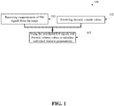
- FIG. 1 is a flowchart 100 of a method of deriving one or more individual thoracic parameters of a subject by using EM measurements from a thoracic intrabody area of the lungs and correlated (for example concurrent) thoracic volume values of her lungs, according to some embodiments of the present invention.
- the one or more individual thoracic parameters which have a direct or indirect measurable effect on the propagation of EM signals through the subject's body, are used for personalizing, for example personalizing a model that is used for EM signals, and/or calibrating one or more thoracic tissue measurements and/or diagnostic devices, for brevity referred to herein as thoracic analysis devices.
- the one or more individual thoracic parameters may be or include or be derived from or indicative of or otherwise represent parameters of a subject's thorax that are, or are affected by, one or more of the subject's heart dimensions, heart position, fat layer size, muscle and rib dimensions, lung volume, lung dimensions, thorax dimensions, thoracic dimensions including antero-posterior depth dimensions, lateral width dimensions and/or the like, breathing characteristics, for example functional residual volume of the lung and/or the like.
- the individual thoracic parameters may include or be derived from or indicative of or otherwise represent dielectric related properties of one or more of the tissues and/or organs of the thorax of the subject.
- the individual thoracic parameters may be or include parameters of a dielectric model of the thorax of the subject and/or a model that maps changes of dielectric related properties of the lungs when physiological and/or pathophysiological processes occur, for example the process of breathing.
- the individual thoracic parameters may be extracted as part of a preliminary session for calibrating the thoracic analysis device, and/or a repetitive process which continuously, randomly and/or iteratively adapts the thoracic analysis device and/or the like.
- the method may be implemented independently to extract individual thoracic parameter(s) without using imaging modalities.
- EM measurements may be measurements of EM radiation and/or signal that is used for monitoring a thoracic tissue parameter, for example fluid level, for example as described in international patent publication number WO2009/031149 and/or international patent publication number WO2009/031150 , which are referred to as the international patent publications.
- the measurements of EM radiation may be performed in one or more monitoring sessions by any thoracic monitoring device which monitors a thorax and is attached and/or in proximity to the thorax.
- the EM measurements may be of EM radiation, such as a single EM beam, induced into the thorax and/or received therefrom by the thoracic monitoring device, and is a narrow bandwidth signal, although other acquisition regimes are possible such as wide bandwidth signals.
- thoracic volume values may include one or more of breathing values such as tidal volume, air volume (e.g. at one or more points in time), functional residual capacity, minute ventilation, lung volumes, thorax and lung dimensions(e.g. at one or more points in time), and breathing rates.
- breathing values such as tidal volume, air volume (e.g. at one or more points in time), functional residual capacity, minute ventilation, lung volumes, thorax and lung dimensions(e.g. at one or more points in time), and breathing rates.
- a thoracic analysis system may comprise a thoracic analysis device which uses measurements of EM signals to monitor and/or assess and/or provides clinical parameters related to the state of pathologic and/or disease conditions related to the thoracic tissues and/or organs, for example conditions such as heart failure (HF), acute respiratory distress syndrome (ARDS), acute lung injury (ALI), chronic obstructive pulmonary disease (COPD), pneumonitis, pleural effusion, oncologic diseases, postoperative edema, pneumothorax, and/or for monitoring the subject's response to treatment of these or other disease conditions.
- HF heart failure
- ARDS acute respiratory distress syndrome
- ALI acute lung injury
- COPD chronic obstructive pulmonary disease
- pneumonitis pneumonitis
- pleural effusion oncologic diseases
- postoperative edema pneumothorax
- pneumothorax pneumothorax
- the system may be used for finding dielectric related properties indicating the amount of fluids, such as water, blood, and/or inflammation fluids in the monitored internal tissue and/or organ, for example, in the pulmonary tissues of the subject.
- the system may be associated with, or comprise (e.g. as a single combined device), a thoracic monitoring device that receives EM signals from the subject's thorax, where these signals may be used for said analysis and monitoring.
- receiving measurement of EM signals or receiving of EM signals may include receiving data indicative of said signals and/or derived from said signals in any form, including for example a mathematical representation and/or derivation from the measurements.
- a dielectric related property of a specific volume describes its interaction with EM fields; it is represented by a frequency dependent complex number describing the electrical permittivity and the conductivity of the volume, as known in the art. It includes the magnetic permeability, and/or electric permittivity and/or conductivity of the composite of materials within a specific volume.
- Such a dielectric related property may be affected by a presence or distribution of fluid, concentration of substances, such as salts, glucose, in the fluid in the internal tissue and/or organ, the ratio of fibrotic tissue, a concentration of inflammatory substance in the fluid in the internal tissue and/or organ and physical configuration of organs or tissues of different properties in the volume measured.
- Electric properties, dielectric related properties, and dielectric coefficients are used interchangeably in this application, all referring to the electrical and/or magnetic characteristics of a certain volume containing none, one or more materials.
- the dielectric related properties of a material derived from the intercepted EM radiation, describe its interaction with the EM fields.
- Different human tissues are characterized by different dielectric related properties.
- the dielectric related properties of a pulmonary tissue are affected by the dielectric related properties of each of its components.
- a pulmonary tissue comprises blood, lung parenchyma and air, and its dielectric related properties are affected by their relative concentrations.
- the dielectric related properties of a tissue are determined predominantly by its fluid content.
- a fat tissue which is of low fluid content
- a healthy muscle tissue which is of relatively high fluid content
- the dielectric related properties of a tissue affect the delivered EM radiation which interacts with the tissue.
- a change in the dielectric related properties of a tissue may be, for example, a change of the attenuation of a delivered EM radiation, a change in the delay caused by the tissue, a change in the phase modulation of interception, and a change in the dispersion of EM radiation in a tissue.
- the thoracic analysis device may be a device used for diagnosing, for example assessing clinical parameters such as breathing volumes, such as tidal volume, residual volume, functional residual capacity total lung volumes, and minute ventilation.
- breathing parameters may also provide indication of a medical condition, and may help to decide on a treatment, or treatment adjustment, or treatment change, possibly a preventive treatment in order to prevent the development of symptomatic pulmonary edema and/or other severe medical state in a subject. In certain medical situations, such a preventive treatment may reduce morbidity and mortality rates.
- the clinical parameters and/or the breathing parameters may be fluid and/or gas volume in thorax and/or lung tissue values, percentage of fluid in a lung tissue, parameters indicative of fluid content and/or content change, and/or percentage of fluid change in lung tissue.
- the method 100 of FIG. 1 may be used for calibration.
- the calibration performed according to embodiments described herein may allow deriving clinical parameters such as volumetric and/or functional lung parameters in a more accurate manner. Such accurate clinical parameters may be used in the process of diagnosis, tissue and/or organ monitoring and/or performance assessment and/or medical decision aiding procedure.
- the calibration described herein reduces effects of specific anatomical, physiological and/or biological characteristics that may reduce the accuracy of the estimation of these clinical parameters.
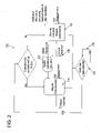
- FIG. 2 showing a flowchart 120 depicting a process of using a thoracic analysis device for monitoring clinical parameters of a subject based on an analysis of measurements of EM signals from the thorax of a subject where the measurements are calibrated according to individual thoracic parameters or analysis thereof, according to some embodiments of the present invention.
- individual thoracic parameters are derived, for example as depicted in FIG. 1 and detailed below.
- the individual thoracic parameters or information relating to the individual thoracic parameters e.g.
- information indicative of the parameters and/or derived from the individual thoracic parameters may be stored as calibration data for later use, for example as parameters of a dielectric model.
- clinical parameters are also derived using the same EM measurements, as shown in 126.
- a single device is used to derive individual thoracic parameters and to use them to derive clinical parameters using the same and/or later EM signals.
- operational EM measurements are analyzed using the calibration data to extract clinical parameters, for example, at one or more later measurement sessions.
- the process depicted in 121-123 is repeated.
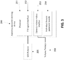
- FIG. 3 is a schematic illustration of a device 200 for deriving individual thoracic parameters of a subject, optionally based on the method of FIG. 1 , according to some embodiments of the present invention.
- the individual thoracic parameter(s) deriving device 200 may be a component of an analysis system for monitoring thoracic fluid or a separate calibration device.
- the individual thoracic parameter(s) deriving device 200 optionally includes a processor 201, for example a microprocessor, an EM signals interface 202 which receives measurements of EM signals from one or more EM probes 205 that is directed to capture EM signals from a thoracic intrabody area of lungs of a subject.
- the one or more EM probes 205 may be included with the processor 201 in a single device or be otherwise associated one with the other so as to provide the EM signals interface 202 with measurements of EM signals taken from the one or more EM probes 205.
- the probe 205 includes one or more transducers each with one or more antenna(s). One or more transducer(s) may be used for transmitting an EM signal beam while other transducer(s) may be used for intercepting the EM signal beam, or the same transducer may be used for capturing the reflected EM signal beam.
- the EM signals interface 202 may communicate with the transducer(s) via a subject management unit, for example as described in the International Patent Publication Number WO/2011/141915 filed on May 12, 2011 . For example, the EM signal beam passes through lungs, for example from one side to another and/or reflected from an internal object in the body, such as the heart.
- the EM measurements may be taken at different states of the lungs where in each state the lungs have a different thoracic volume.
- the different thoracic volumes may be achieved during a thoracic volume manipulation undergone by the subject.
- the individual thoracic parameter(s) deriving device 200 further includes a thoracic volume value interface 203.
- the thoracic volume value interface 203 may receive thoracic volume values from one or more volume probe(s) 206, for example as described below.
- thoracic volume value(s) and a measurement(s) of EM signals taken during a common thoracic volume manipulation may be correlated.
- the individual thoracic parameter(s) deriving device 200 includes an individual thoracic parameter module 204 which uses the processor 201 to derive one or more individual thoracic parameters using the EM signal measurements and correlated thoracic volume values.
- measurements of EM signals from a thoracic intrabody area of lungs of the subject are received.
- the measurements are taken at a set of different thoracic volumes, which are optionally achieved during a thoracic volume manipulation undergone by the subject, for example as described below.
- the subject may be instructed to perform the thoracic volume manipulation, or the thoracic volume manipulation may be applied to the subject, in correlation with the operation of the individual thoracic parameter(s) deriving device 200.
- the subject may perform the thoracic volume manipulation while operation of the individual thoracic parameter(s) deriving device 200 is operated in correlation with the subject's performance of manipulation.
- individual thoracic parameter(s) deriving device 200 operates irrespective of the performance of the thoracic volume manipulation, but data and/or information are analyzed in correlation with the performance of the thoracic volume manipulation.
- thoracic volume values for example thoracic fluid and/or air volume values
- the thoracic volume values are taken during the set of different thoracic volumes which are optionally achieved during the thoracic volume manipulation.
- the subject is instructed to perform said thoracic volume manipulation in a correlated manner with the deriving of the thoracic volume values.
- instructions may be presented, for example audibly played and/or visually displayed correlatively with the outputs of the volume probe(s).
- EM measurements and thoracic volume values are used to calculate one or more individual thoracic parameters at each one of the different thoracic volumes by combining between respective correlated EM measurements and thoracic volume values.
- the depth of the lung (D) or the thickness of some of the layers may change, for instance as an outcome of a thoracic volume manipulation, for example the subject's breathing.
- a thoracic analysis device for example to reduce or limit the effect of bodily movements of the chest during the measurement of the EM measurements, for example movements associated with the breathing process and/or other movements, movements are measured and modeled.
- an electromechanical device in a form of a strap may be placed around the chest of the subject to provide real-time continuous measurements of thoracic volume values, for example the subject's chest circumference, and or in other forms to provide a measurement of the depth of the thorax (front to back), while s/he is measured by the thoracic monitoring device the measurements of EM signals taken by which may be used to monitor thoracic fluid.
- thoracic volume values for example the subject's chest circumference
- EM signals taken by which may be used to monitor thoracic fluid.
- the subject may be instructed to perform abdominal breathing to minimize the movement of the rib cage and the expansion of the lung during breathing as a result of the downward expansion of the lungs in such breathing replacing much of the sideward expansion associated with regular breathing.
- Such breathing may be encouraged by providing the subject with feedback, for example by using the abovementioned electromechanical circumference measurement device, indicating when minimal changes of the chest circumference are detected.
- Another such option would be to use the circumference measurement device, or tiltmeter devices or accelerometer devices or other such devices in order to follow the movement of the rib cage and select periods of time during which minimal movement are detected.
- the subject In order to measure thoracic volume values during a set of different thoracic volumes, the subject is instructed to perform or is subjected to a thoracic volume manipulation, for example by breathing in a certain manner. For example the subject may be instructed to breathe normally for a given time, then in an extreme manner (e.g. deep exhalations and inhalations) for another period of time.
- GUI graphical user interface
- the subject is required to inhale or exhale a predefined air volume during the monitoring of the lung, for example while EM signal is received from her lungs.
- This process may be implemented using an apparatus that measures and/or controls the amount of air that is inhaled and/or exhaled.
- an air flow meter which measures the amount of inhaled and/or exhaled air, for instance a pneumotach or a spirometer, is used for instructing the subject and identifying thoracic volume values taken during a set of known thoracic volumes.
- a bag, a balloon and/or an air container may be used for controlling the inhaling and/or exhaling volume of the subject, where the bag, the balloon and/or the air container has a known capacity and the subject is required to exhale into the balloon until the balloon inflates into a predefined capacity, or where the subject is required to inhale from the balloon until the balloon deflates from its predefined capacity.
- a piston like air chamber may be used for measuring and/or controlling air volume inhaled and/or exhaled by the subject, where optionally an indicator on the chamber indicates the volume of air inhaled and/or exhaled.
- the thoracic volume manipulation includes control and /or measurement of the volume of air in a subject's lungs using an artificial respiration device, for example a ventilator, (for example when the subject is anesthetized, comatose or otherwise incapacitated).
- an artificial respiration device for example a ventilator, (for example when the subject is anesthetized, comatose or otherwise incapacitated).
- thoracic volume values are taken during the set of different thoracic volumes which are achieved using an air supply apparatus which supplies air for inhalation, and collects exhaled air in a controlled and or measured quantity.
- a mechanical ventilator may be used.
- the air supply apparatus is connected to a monitoring apparatus and measures airflow concurrently with the measurements of EM signals from the lungs of a subject for identifying individual thoracic parameters, optionally for the calibration of the monitoring apparatus.
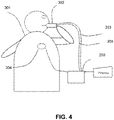
- FIG. 4 depicts a subject 301 who exhales and inhales in a controlled manner via an instrument for measuring air flow 302, such as a spirometer, while the individual thoracic parameter(s) deriving device 200 concurrently measures EM signals from the lungs using one or more probes 304.
- the instrument for measuring air flow302 may be supported by air from a pump, for example via a pump tube 305.
- the measurements from the instrument for measuring air flow 302 are forwarded to the individual thoracic parameter(s) deriving device 200 for processing as described herein, for example via a data link 303.
- Such controlled or measured changes of air volumes are indicative of individual thoracic parameters, namely dielectric related properties of the lungs, optionally in a manner that is described in a dielectric thorax model, for example as described below. This allows calibrating the model based measurements.
- Metadata is received and used for adjusting the calculated individual thoracic parameters.
- the metadata may include user generated metadata such as demographic parameters describing the subject, for example age, gender, height, weight, and/or anatomical dimensions.
- the metadata may include and/or be derived using data measured by mechanical measuring devices, inferred from radiographic images and/or extracted using other means. Using this information the apparatus the individual thoracic parameters may be calculated more accurately.
- the individual thoracic parameter(s) deriving device 200 uses one or more body attached sensors to obtain EM measurements while measurements of air quantities, which are inhaled and exhaled by the subject, are provided to the individual thoracic parameter(s) deriving device 200via a flow meter.
- a model describing the dielectric properties of the lung at different thoracic volume values is used to generate a set of equations to derive the one or more individual thoracic parameters.
- a model optionally represents a relationship between dynamic lung content parameters, such as lung air and lung fluid, such as blood, and the individual thoracic parameters optionally in different thoracic volumes.
- the dielectric model may describe the dielectric related property of the lung as a function of dielectric related properties of air, lung fluids, and lung tissues, and their respective volumes, composition, and/or concentration.
- the lung of a normal person is composed of approximately 0.5 liter (L) to 0.8L of blood, approximately 0.5L of lung tissue, and approximately 1.5-5L of air, depending on the amount or air inhaled and exhaled in the process of breathing.
- the overall lung dielectric coefficient may be estimated to be the average of the dielectric coefficients of the three components of air, blood and tissue according to their respective volume and concentration.
- Another option is to estimate the equivalent dielectric coefficient by averaging a square root of the dielectric coefficients according to a respective volume concentration, and calculating a square of the total.
- dielectric models for estimating the equivalent dielectric coefficient of a mixture exist. Such methods may be used to model the lung and/or other thoracic tissues and/or organs' dielectric properties at different periods along the breathing cycle and for different edema states or other lung changes. For example, at the end of inspiration a model can assume 2 liters of air present in the lungs, and 1.5 liters of air content at the end of expiration.
- the dielectric thorax model is defined as a chest wall model as described in international patent publication number WO2009/031150 filed on September 4, 2008 .
- Equations 1-7 are a mathematical description of an exemplary dielectric thorax model and a process of acquiring individual thoracic parameters which are substituted in the dielectric thorax model for calibration.
- E ratio E r E t
- E r E t f ( V , V fluid , V air , Dielectric properties of the thoracic tissues, Anatomical parameters)
- V denotes a total lung tissue volume composed of gas (i.e. air) and lung fluid
- V fluid denotes a total volume of fluids in the lung, for example measured in cubic centimeter (CC)
- the fluid content comprises a combination of extravascular, intravascular, and intracellular fluid
- V air denotes lung air content in volume units.
- E ratio E r E t denotes a ratio between a received (i.e. intercepted; E r ) signal and a transmitted (i.e. induced; E t ) signal in terms of the electrical component of the EM field.
- lung fluid includes tissue contents and fluids including blood.
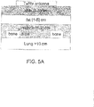
- the dielectric thorax model is modeled as stacked layers, such as skin, fat, muscle, and lung, where each layer has a different dielectric property, for example as depicted in FIG. 5A .
- the reference chest wall model maps expected dielectric coefficients of tissues of an exemplary reference model of EM properties of tissues of a thorax section.
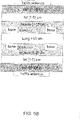
- the model at FIG. 5A includes the following layers with the following possible thicknesses: a skin tissue layer (1-3mm), a fat tissue layer (50-500mm), a muscle tissue layer (50-200mm), a bone layer (30-60mm), and a pulmonary tissue layer ( ⁇ 100mm). Another example is depicted at FIG.
- 5B which is a side to side model that includes the following layers with the following possible thicknesses: a skin tissue layer (1-3mm), a fat tissue layer (1-5cm), a muscle tissue layer (1-2cm), a bone layer (0.5cm), a pulmonary tissue layer ( ⁇ 100mm), a bone layer (0.5cm) a muscle tissue layer (1-2cm), a fat tissue layer (1-5cm), and a skin tissue layer (1-3mm).
- the reference chest wall model includes one or more of the following parameters: a relative dielectric coefficient, thickness, for example as described above, an estimated signal shape, and an equivalent frequency response of a layer capturing an effect imposed on an EM signal propagating therethrough, for example an estimation of attenuation and dispersion of a pulse which propagates through the respective layer.
- E rat ⁇ o ⁇ e ⁇ j 2 ⁇ f C ⁇ ⁇ i ⁇ tissues D i ⁇ ⁇ i + j ⁇ ⁇ ′ i
- E ratio denotes a measured phasor relationship between a transmitted signal and a received signal representing the electrical components of the electromagnetic radiation at a given frequency
- D i denotes a propagation distance within i th layer (layer thickness) for example skin layer or fat layer
- ⁇ i and ⁇ ' i denote real and imaginary parts of dielectric permittivity (dielectric coefficient) of the i th layer
- f denotes a frequency for which the phase shift is calculated
- ⁇ denotes a Pi constant
- C denotes a speed of light in vacuum constant.
- RFC root fluid concentration
- each of a set of thoracic volume values is measured during another of a set of different thoracic volumes which are achieved in a controllable manner.
- controlled and/or measured changes in air content enables extraction of individual thoracic parameters.
- a deflated volume for example end of expiration volume, also known as a functional residual capacity (FRC) state of the lung
- FRC functional residual capacity
- V deflated denotes a total lung capacity at the end of expiration by substituting known values of inhaled quantities, for example three or more, for instance ⁇ V 1 , ⁇ V 2 and ⁇ V 3 and corresponding phase measurements, for instance ⁇ 1 , ⁇ 2 and ⁇ 3 .
- the subject is instructed to perform, for example sequentially, a combination of breathing patterns, for example forced exhale pattern, maximal inhale pattern, and normal breathing patterns and the estimated breathing values are used to infer values for ⁇ V 1 , ⁇ V 2 and ⁇ V 3 ,
- a combination of breathing patterns for example forced exhale pattern, maximal inhale pattern, and normal breathing patterns and the estimated breathing values are used to infer values for ⁇ V 1 , ⁇ V 2 and ⁇ V 3 ,
- V fluid a measurement or estimation of D lung allows calculating V fluid .
- the acquired individual thoracic parameters may be used for calibration.
- the extracted V deflated (i.e. FRC) and V fluid are two individual thoracic parameters which allow deducing another individual thoracic parameter, fluid concentration (FC).
- FC fluid concentration
- the individual thoracic parameters are used for adjusting an analysis of EM measurements obtained while monitoring of intrabody thoracic tissues.
- Equations 9-19 are a mathematical description of an exemplary dielectric thorax model, a nonlinear mixture model, and a process of acquiring individual thoracic parameters which are substituted in the nonlinear mixture model for calibration.
- the individual thoracic parameters are dielectric lung constants.
- FC V fluid V deflated
- relative parameters are extracted; for example, a lung fluid change.
- the thoracic volume values are taken during the set of different thoracic volumes which are optionally achieved during a thoracic volume manipulation.
- the subject is instructed to perform a Valsalva maneuver and/or Miller maneuver (also known as Muller's maneuver) while electromagnetic waves are measured, optionally using a closed volume chamber apparatus.
- the subject may, for example, be instructed to exhale normally and from the end of the expiration or the end of inspiration state to perform a Valsalva and/or Miller maneuver.
- the Valsalva maneuver is performed when the subject exhale against a closed airway, usually when closing his mouth and pinching his nose.
- the Miller maneuver is performed when the subject inhales against a closed airway, usually closes his mouth and pinches his nose, optionally at the end of expiration.
- the subject is instructed to perform the maneuver for a timed duration.
- Equation 6 may be set as follows: ⁇ ⁇ ⁇ ⁇ + 450 ⁇ D lung ⁇ V fluid + ⁇ VF i V deflated where ⁇ VF denotes an amount of blood fluid removed and/or added by the maneuver.
- ⁇ VF denotes an amount of blood fluid removed and/or added by the maneuver.
- different parameters for a number of equations may be generated by instructing the subject to perform several maneuvers. Similar to the above, three such equations allow deducing the following individual thoracic parameters: ⁇ , V fiuid , and a term D lung / V defalted . Obtaining D lung allows calculating V deflated .This method may be combined with other methods for creating controlled and/or measured changes in the characteristics of the thorax or the lung and the corresponding model parameters.
- the subject is instructed to perform a Miller and/or Valsalva maneuver while electromagnetic waves are measured, optionally using a closed volume chamber apparatus.
- the Miller maneuver involves forcible inhalation against a closed airway. It may be performed in a similar manner to a Valsalva maneuver with similar results (increasing the amount of blood fluid in the lungs). It may be performed with or without a duration definitions, with or without additional pressure measurement of the intensity and/or control of the negative air pressure; and may be controlled using a similar closed volume chamber apparatus.
- maneuvers may also be used to change the amount of fluid in the lung in a controlled manner. For example, a change of posture, change of position, a change of lying angle, a change of posture from sitting to lying or vice versa, a raising of the legs in a lying position and/or the like.
- These maneuvers may be controlled and/or measured to improve accuracy, for example the posture or posture change may be measured and timed, for example using tilt meters, accelerometers, gyroscopes and/or the like.
- the angle of the torso and/or the angle of the legs may be measured or controlled during the maneuver. Also the duration of the maneuver or its parts may be measured.
- peripheral effects for example blood pressure, heart rate, respiration rate, may be measured before during or after the maneuver to help in the assessment of the extent of the maneuver and the expected change in the fluid content of the lungs.
- a given maneuver creates a new equilibrium state that removes or adds a given amount of fluid to the thorax.
- the change, measured in the intercepted EM signal, during the controlled change induced in the subject, may be analyzed, using a dielectric thorax model, to estimate the individual thoracic parameters for the dielectric thorax model.
- the individual thoracic parameters may be used to in order to calibrate thoracic analysis device. Therefore, by inducing a controlled change of the dielectric related properties of a monitored lung, for example, while performing EM measurements of the lung, it is possible to track the changes in the received EM signal in view of the induced change. This method may be used to calculate parameters of the model for the subject being monitored using the EM measurements.
- controlled changes may be induced once, several times, periodically, and/or continuously throughout an EM measurement session and/or a monitoring period, in one or more manners, and using one or more degrees of intensity.
- These controlled changes may include the use of the above methods, and/or other techniques for changing the dielectric related properties of the measured tissue, as mentioned above.
- the EM signal is measured while the subject performs the above maneuvers.
- FIG. 6 depicts phase 171 and amplitude 172 of an EM measurement signal captured while the subject performed a Valsalva maneuver and analyzed over a period of a few minutes and modulated by the breathing of the subject. Three periods where the Valsalva maneuver is performed and a respective removal of a specific volume of blood from the subject's lung are seen at 173-175. EM measurements may be taken during one or more of the maneuvers and/or at a time when the maneuver is not performed.
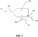
- the thoracic volume values are taken during the set of different thoracic volumes which are acquired using a closed volume chamber apparatus, for example the volume chamber apparatus 161 depicted in FIG. 7 .
- the closed volume chamber apparatus 161 indicates air pressure in the lung of the subject over a measured amount of time.
- the subject is instructed to inhale or to exhale against the closed chamber 162 through a single airflow opening, for example a mouthpiece 163, while the apparatus 161 induces and/or measures air pressure in the chamber 162 using an air pump 165 and/or a pressure sensor 164.
- the pump 165 and the pressure sensor may be connected with data links 167/8 to an individual thoracic parameter(s) deriving device 200.
- the apparatus 161 may be controlled by a processing unit that may be embedded in the closed volume chamber apparatus 161.
- the processing unit may record the pressure measurements, and/or measure the duration that the pressure is maintained and/or control the air pump to create the desired pressure in the chamber.
- the processing unit may communicate with a subject interface unit to provide information to be used as a basis for instructing the subject to achieve the desired behavior (inhaling or exhaling against the closed chamber to create the desired pressure) for the desired duration.
- apparatus 161 may be used to extract the thoracic volume values during a set of identified thoracic volumes.
- the individual thoracic parameters include estimated physiological parameters of the subject.
- the ratio between the lung's depth (e.g. anteroposterior dimension of the lung) and the square root of the lung volume may also be assumed based on the general population, and/or adjusted based on subject specific characteristics for example weight, height, chest, circumference, and the like.
- tidal volume is assumed to be an average volume, for instance for an adult 500 cubic centimeter (cc) and/or adjusted based on the weight of the subject, for instance assuming a value for a normal individual at rest of 7 milliliter (mL) per kilogram (kg) of body weight and/or in correlation with BMI or fitness level and/or any other subject specific characteristic.
- the tidal volume may be estimated based on average minute ventilation (defined as the tidal volume multiplied by the respiration rate given as breaths per minute) of, for example, 6 liters per minute and adjusted based on a measured respiration rate, see "Tintalli's Emergency Medicine, Ch. 22"; Todd L. Slesinger, M.D.; 2011.
- respiratory functional residual volume may be estimated as the general population overage of 2500cc and/or based on weight and age of the subject, for instance (0.0275 ⁇ Age[years]+0.0189 ⁇ Height[cm]-2.6139) liters for normal-weight individuals and (0.0277 ⁇ Age[years]+ 0.0138 ⁇ Height[cm]-2.3967) liters for overweight individuals, see MILLER, WAYNE C.; SWENSEN, THOMAS; WALLACE, JANET P. (February 1998). "Derivation of prediction equations for RV in overweight men and women", Medicine & Science in Sports & Exercise 30 (2): 322-327 .
- the clinical parameters include breathing parameters such as a breathing rate, minute ventilation, a tidal volume, a residual volume, and/or FRC.
- the breathing values used as thoracic volume values, for example the tidal volume, are used for calibrating using an EM probe that captures EM signals from the lungs.
- the EM measurements may be used to continue and provide the tidal volume measurements; and in addition minute ventilation may be provided by using the tidal volume measurement multiplied by a breathing rate value.
- the breathing rate value may be assessed using one or more frequency analysis methods applied to the measured EM signal. For example, looking for a maximum power peak in the frequency domain, a representation of the phase of the measured EM signal in a range between 2/60 Hertz (Hz) and 1 Hz, after employing methods for removing the effects heart beating from the signal.
- Hz 2/60 Hertz
- residual volume may be calculated using the above method while the subject exhales as much as she can.
- the resulting equation ⁇ i ⁇ ⁇ ⁇ + 450 ⁇ D lung ⁇ V fluid V RV + ⁇ Vi may be used with controlled and/or measured changes in air content to obtain RV.
- Breathing parameters are of importance in relation to several pathologies and medical conditions, for example heart failure, chronic obstructive pulmonary disease (COPD), interstitial lung disease (ILD), and/or acute lung injury (ALI).
- COPD chronic obstructive pulmonary disease
- ILD interstitial lung disease
- ALI acute lung injury
- a noise model is generated and used to improve the calculation of the individual thoracic parameters, for example using a least square error method.
- a thoracic analysis device is calibrated based on individual thoracic parameter(s) which are calculated independently from information about current thoracic volumes.
- the individual thoracic parameter(s) may include a lung diameter that is approximated according to the average in the population estimated at about 17.1 centimeters (cm) or any other appropriate estimated average. This and other approximations may be more accurate if they are estimated based on the subject's general physical parameters, such as height, weight, body mass index (BMI), age, gender and/or fat-muscle ratio. Another option is to approximate lung diameter according to a chest perimeter of the subject.
- the chest perimeter may be measured under the armpits of the subject and multiplied by a factor such as 0.164 (or any other appropriate factor).
- lung diameter is approximated according to chest depth of the subject.
- the chest i.e. depth front to back
- the measuring is optionally correlated with phase shift measuring and optionally multiplied by a factor.
- thoracic parameter(s) are individual thoracic parameters measured using an imaging modality, such as computerized tomography (CT), magnetic resonance imaging (MRI), ultrasound imaging, and/or radiographic, and/or other imaging methods or any other known system for finding the lung width along the measurement path.
- CT computerized tomography
- MRI magnetic resonance imaging
- ultrasound imaging and/or radiographic, and/or other imaging methods or any other known system for finding the lung width along the measurement path.
- CT computerized tomography
- MRI magnetic resonance imaging
- ultrasound imaging and/or radiographic, and/or other imaging methods or any other known system for finding the lung width along the measurement path.
- radiographic radiographic
- fluid to air ratio of the lung tissue, fat tissue and/or other tissues may be estimated based on the analysis of image gray levels in regions of interest in a CT image, or other imaging modalities.
- Such an analysis of a CT image to assess lung fluid concentration may be performed by extracting a three dimensional (3D) region of interest in the image, say within the lung, or the entire lung region; and computing the average attenuation level of the region in Hounsfield units (HU).
- HU may be converted into fluid concentration (i.e. the ratio of the volume of blood, parenchyma and any pathological fluid to the total volume) using a linear scale.
- Transformation from HU to fluid concentration percentage may be performed by assigning a value between 0% and 100% along the range of HU values, between 1000 HU (the calibrated radiodensity of air) and 0 HU (the calibrated radiodensity of water), for instance 800 HU is equivalent to 80% air content and 20% fluid concentration.
- Another example of independently calculated individual thoracic parameter(s) are individual thoracic parameters measured using EM signal reflected from the thorax, for example the measuring of D as described in Staderini EM, UWB radars in medicine, IEEE Aerospace and Electronic Systems, Volume: 17 (1) 2002 .
- breathing values are quantified by processing amplitude of an intercepted signal in relation to a delivered signal and used, in conjunction with a model, such as the above dielectric thorax model, to calculate individual thoracic parameters.
- the model may be adjusted for other analyses of other signals, for example EM signals which are transmitted and captured from a probe that is attached on the back, the chest, and/or below the arm of the subject.
- Amp
- extracted V deftated and V fluid are two of the individual thoracic parameters of interest.
- the above models share parameters to create a hybrid model that can enhance the accuracy of the results of the estimation of the individual thoracic parameters.
- Combinations of the models may be implemented as extended sets of equations solved in any of the mentioned methods or others known in the art.
- any of the aforementioned models may be combined with one another and/or with other models.
- multiple frequencies may be used by a thoracic monitoring device and/or thoracic analysis device.
- the above and other possible models may be used with a varied frequency content to obtain an accurate estimation of the parameters in view of measurement errors.
- ⁇ c fluid given in the above models and assuming a given frequency, has different values at different frequencies.
- Performing measurements at multiple frequencies creates a plurality of linearly independent sets of equations, allowing more accurate estimations of the individual thoracic parameters.
- Multiple frequencies measurements may be measured substantially simultaneously to create additional equations with the same air content status of the lung at the same point in time.
- Similar thorax models to the ones above may be used with multiple frequencies based thorax analysis devices for modeling effects of individual thoracic parameters and obtaining clinical parameters. Additionally in a similar manner similar methods for deriving individual thoracic parameters using multiple frequencies can be employed.
- measurements at multiple frequencies are used to overcome one or more phase ambiguity problems, for example 2 ⁇ P i uncertainty in the measured phase in the presence of measurement noise that may arise when analyzing a phase of a low bandwidth signal.
- phase ambiguity problems for example 2 ⁇ P i uncertainty in the measured phase in the presence of measurement noise that may arise when analyzing a phase of a low bandwidth signal.
- EM signals from multiple transducers which are placed in multiple locations are separately analyzed.
- two signal transducers are placed in two different locations used to transmit EM signals between them.
- one or more of them may transmit a signal and measure it's reflection in addition or instead.
- additional paths may be employed. This may allow, for example, reducing measurement errors.
- Multiple locations may allow receiving EM signals passing via multiple paths. Assuming that the paths are in the same general region, fluid content in each path may be assumed to be the same. Thus, for each such path, a different equation may be solved to calculate the individual thoracic parameters of interest. For example, in any of the above models each path is associated with a different D lung parameter. Simultaneous measurements may be used in a single equation system, with more linearly independent equations, that may be used for more robust estimations under certain measurement noise conditions.
- less than three measurements are used, for example when parameters are from different sources, for instance when the volume of the lungs is received from an external device and/or inputted by the subject and/or any operator.
- multiple locations and multiple frequencies may be combined to create one or more equation systems that increase robustness of the estimation of the individual thoracic parameters.
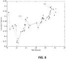
- FIG. 8 is an experiment graph reflecting a calculation of lung fluid concentration 311 calculated based on EM measurement of an animal subject compared to a CT based estimation 312 of the same parameter based on multiple images acquired along the course of the experiment.
- the experiment is held concurrently with breathing volume spirometer measurements, and using the above mentioned model describing signal phase and signal amplitude, with a linear mixture model and a mechanical measurement based estimation of D.
- the graph depicts the fluid concentration, also referred to as fluid content, parameter estimation done multiple times over the course of four hours while the animal lung fluid has changed rapidly using a systemic saline overload experiment protocol.
- the EM signal is a reflected signal
- a model that takes into account the back and forth route of the EM wave may be employed.
- S 11 V R 0 + C ⁇ 1 ⁇ ⁇ lung V ⁇ 1 + ⁇ lung V
- ⁇ 1 denotes a dielectric coefficient of the lung wall
- ⁇ lung denotes a dielectric coefficient of the lung tissue
- V denotes a lung volume
- R 0 C denotes constants related to other tissue layers which are more proximate to the probe and the properties of the probe.
- ⁇ lung ⁇ V ⁇ air V deflated ⁇ V fluid + ⁇ V + ⁇ fluid V fluid V deflated + ⁇ V
- V deflated denotes a total lung volume at rest (FRV)
- ⁇ lung 0 ⁇ air V air + ⁇ fluid V fluid V deflated
- the difference between the signals may be estimated to eliminate R 0 :
- S 11 ⁇ V 1 ⁇ S 11 0 ⁇ 1 ⁇ ⁇ lung ⁇ V 1 ⁇ 1 + ⁇ lung ⁇ V 1 ⁇ ⁇ 1 ⁇ ⁇ lung 0 ⁇ 1 + ⁇ lung 0
- V defiated , ⁇ 1 , ⁇ air , ⁇ fluid V deflated , ⁇ 1 may be deduced from other means of measurements and ⁇ air , ⁇ fluid are known constants.
- the above equation may be used to find V fluid , for example using a numeric scheme.
- composition or method may include additional ingredients and/or steps, but only if the additional ingredients and/or steps do not materially alter the basic and novel characteristics of the claimed composition or method.
- a compound or “at least one compound” may include a plurality of compounds, including mixtures thereof.
- range format is merely for convenience and brevity and should not be construed as an inflexible limitation on the scope of the invention. Accordingly, the description of a range should be considered to have specifically disclosed all the possible subranges as well as individual numerical values within that range. For example, description of a range such as from 1 to 6 should be considered to have specifically disclosed subranges such as from 1 to 3, from 1 to 4, from 1 to 5, from 2 to 4, from 2 to 6, from 3 to 6 etc., as well as individual numbers within that range, for example, 1, 2, 3, 4, 5, and 6. This applies regardless of the breadth of the range.
Landscapes
- Health & Medical Sciences (AREA)
- Life Sciences & Earth Sciences (AREA)
- Engineering & Computer Science (AREA)
- General Health & Medical Sciences (AREA)
- Veterinary Medicine (AREA)
- Biophysics (AREA)
- Pathology (AREA)
- Physics & Mathematics (AREA)
- Biomedical Technology (AREA)
- Heart & Thoracic Surgery (AREA)
- Medical Informatics (AREA)
- Molecular Biology (AREA)
- Surgery (AREA)
- Animal Behavior & Ethology (AREA)
- Public Health (AREA)
- Pulmonology (AREA)
- Physiology (AREA)
- Nuclear Medicine, Radiotherapy & Molecular Imaging (AREA)
- Radiology & Medical Imaging (AREA)
- Signal Processing (AREA)
- Cardiology (AREA)
- Hematology (AREA)
- Artificial Intelligence (AREA)
- Computer Vision & Pattern Recognition (AREA)
- Psychiatry (AREA)
- Dentistry (AREA)
- Oral & Maxillofacial Surgery (AREA)
- Measurement Of The Respiration, Hearing Ability, Form, And Blood Characteristics Of Living Organisms (AREA)
- Measuring And Recording Apparatus For Diagnosis (AREA)
- External Artificial Organs (AREA)
- Magnetic Resonance Imaging Apparatus (AREA)
Description
- This application is claims priority from
US provision al patent application No. 61/591,915, filed on January 29, 2012 - The present invention, in some embodiments thereof, relates to EM signal analysis and, more particularly, but not exclusively, to EM signal analysis devices for monitoring of thoracic biological properties.
- Medical instruments in which an echo of a pulse of EM radiation is used to detect and locate structures in the human body are known, see YOUNG, J. D et. al. Examination of video pulse radar systems as potential biological exploratory tools in LARSEN, L. E., and JACOBI, J. H. (Eds.): 'Medical applications of microwave imaging' (IEEE Press, New York, 1986), pp. 82-105. Such medical instruments includes microwave imaging devices, which may be referred to as tissue sensing adaptive radar (TSAR) or imaging and other medical devices for detecting and possibly imaging internal biological tissues. The use of electromagnetic waves eliminates the need to expose the tissues to ionizing radiation, as performed during X-ray imaging, and to obtain relatively large tissue contrasts according to their water content.
- During the last years, various methods and devices have been developed for diagnosing intrabody tissues of patients using EM radiation. For example, International Patent Publication Number
WO/2009/031149, filed on Sep. 4, 2008 , describes a wearable monitoring device for monitoring at least one biological parameter of an internal tissue of an ambulatory user. The wearable monitoring device comprises at least one transducer configured for EM radiation to the internal tissue and intercepting reflections of the EM radiation therefrom in a plurality of continuous or intermittent EM radiation sessions during at least 24 hours, a processing unit configured for analyzing respective reflections and identifying a change in the at least one biological parameter accordingly, a reporting unit configured for generating a report according to the change, and a housing for containing the at least one transducer, the reporting unit, and the processing unit, the housing being configured for being disposed on the body of the ambulatory user. - Using EM radar for cardiac biomechanics assessment is mentioned in E. M. Staderini, "UWB radars in medicine," IEEE Aerospace and Electronic Systems Magazine, vol. 17, no. 1, pp. 13-18, 2002.
-
US application No. 2004/0006279 teaches a method for generating impedance images of the chest, comprising: acquiring electrical data of the chest, obtaining electrocardiograph data of a patient, analyzing the electrocardiograph data to obtain information about breathing parameters at the time the electrical data was acquired, and reconstructing at least one impedance image of the chest from the electrical data and the information about breathing parameters. The information about breathing parameters reduces the sensitivity of the at least one impedance image to breathing parameters. -
US application No. 2011/0060215 teaches an apparatus and method for non-invasive and continuous measurement of respiratory chamber volume and associated parameters including respiratory rate, respiratory rhythm, tidal volume, dielectric variability and respiratory congestion. In particular, a non-invasive apparatus and method for determining dynamic and structural physiologic data from a living subject including a change in the spatial configuration of a respiratory chamber, a lung or a lobe of a lung to determine overall respiratory health comprising an ultra wide-band radar system having at least one transmitting and receiving antenna for applying ultra wide-band radio signals to a target area of the subject's anatomy wherein the receiving antenna collects and transmits signal returns from the target area. - According to the present invention, there is provided a thoracic analysis device as defined in
claim 1. - Optionally, the first interface is associated with a probe having at least one antenna for capturing a plurality of later EM signals.
- Optionally, the second interface is associated with an instrument for measuring at least one of a breathing airflow of the subject for receiving the plurality of thoracic volume values.
- More optionally, the instrument has a chamber with a single airflow opening to allow the subject to blow therethrough during the thoracic volume manipulation.
- Optionally, the processor is associated with a presentation unit which presents instructions indicative of how to perform the thoracic volume manipulation in a correlated manner with the measurement of the plurality of thoracic volume values.
- Optionally, a memory for storing information relating to the at least one individual thoracic parameter.
- Optionally, a processing unit configured to derive one or more clinical parameters according to the at least one individual thoracic parameter and data relating to electromagnetic (EM) radiation received from an internal tissue of the subject.
- According to some embodiments of the present invention, there is provided a method of deriving a total volume of fluids in the lung as defined in claim 6.
- Optionally, the deriving a plurality of thoracic volume values comprises determining a breathing value of the subject in a plurality of separate instances during the thoracic volume manipulation.
- Optionally, the plurality of thoracic volume values comprise at least breathing value of the subject.
- Optionally, information relating to the at least one individual thoracic parameter is stored during a calibration session of a thoracic analysis device and is used for analyzing a plurality of later EM measurements which are measured during a monitoring session of the thoracic monitoring device.
- More optionally, the calibrating comprises updating a dielectric model of a thorax according to the individual thoracic parameters.
- More optionally, the dielectric model is modeled with a plurality of stacked layers having different dielectric properties and selected from a group consisting of skin, fat, muscle, bone, connective tissue and lung.
- Optionally, the at least one individual thoracic parameter comprises a member of a group consisting of: heart dimension(s), heart position, fat layer dimensions, thoracic muscle dimension(s), thoracic rib dimension(s), thoracic rib position, lung volume, lung dimension(s), and thorax dimension(s.(
- Optionally, the at least one individual thoracic parameter comprises dielectric related properties of at least one of a thoracic tissue and a thoracic organ of the subject.
- Optionally, the at least one individual thoracic parameter is used in combination with at least one EM measurement to derive at least one clinical parameter of the subject.
- Optionally, the plurality of EM signals pass through the lungs.
- More optionally, the plurality of EM signals are reflected from at least one object within the thorax of the subject and pass through the lungs.
- Optionally, the plurality of EM signals are reflected from the lungs.
- Optionally, the plurality of EM signals comprise a plurality of EM signals having a plurality of different frequencies.
- Optionally, further comprising presenting to the subject instructions indicative of how to perform the thoracic volume manipulation.
- More optionally, the method further comprises presenting to the subject breathing instructions for the subject to perform during the thoracic volume manipulation.
- Optionally, the thoracic volume manipulation comprises at least one exhalation and at least one inhalation and performed by the subject.
- Optionally, the deriving at least one individual thoracic parameter is performed according to one or more demographic parameters relating to the subject.
- Optionally, the thoracic volume manipulation is a member of a group consisting of a Valsalva maneuver and a Miller maneuver.
- Optionally, the thoracic volume manipulation includes performing a change of posture, a change of position, a change of lying angle, a change of posture from sitting to lying, a change of posture from lying to sitting, and a rising of the legs.
- Optionally, the deriving at least one individual thoracic parameter is performed according to a measured amplitude ratio between a transmitted signal and a received signal.
- More optionally, the at least one clinical parameter comprises one or more breathing parameters .
- More optionally, the one or more breathing parameters include a member of a group consisting of breathing rate, breathing volumes, tidal volume, residual volume, functional residual capacity (FRC), total lung volumes and minute ventilation.
- More optionally, the at least one clinical parameter comprises a member of a group consisting of fluid and/or gas volume in the thorax and/or lung tissue, percentage of fluid in a lung tissue, parameters indicative of fluid content and/or content change, and/or percentage of fluid change in lung tissue.
- Optionally, the deriving at least one individual thoracic parameter comprises calculating a phase shift based on the plurality of EM measurements.
- Optionally, the deriving at least one individual thoracic parameter comprises calculating a depth of the lungs.
- Also disclosed but not claimed is a method of EM signal analysis. The method comprises receiving at least one individual thoracic parameter of a subject, receiving a plurality of measurements of EM signals from a thoracic intrabody area of the lungs of the subject, and deriving a clinical parameter of the subject using the individual thoracic parameter.
- Optionally, the at least one individual thoracic parameter comprises a ratio between a depth of the lungs and a square root of the volume of the lungs.
- Optionally, the at least one individual thoracic parameter comprises a population average value selected according to at least one demographic characteristic of the subject.
- Optionally, the analyzing comprises deriving dielectric related properties of the lungs according to the plurality of measurements.
- Optionally, the clinical parameter is an indication of lung fluid.
- Also disclosed but not claimed is a system for monitoring one or more clinical parameters of a subject. The system comprises an interface for receiving data relating to electromagnetic (EM) signals received from an internal tissue of a subject, a memory for storing information relating to one or more individual thoracic parameters of the subject, the at least one individual thoracic parameters being the product of a calculation during a calibration session using a plurality of EM signal measurements taken when the subject undergoes at least one thoracic volume manipulation, and a processing unit configured to derive one or more clinical parameters according to the data and the information.
- Optionally, the system further comprises a receiver for intercepting the EM signals.
- Optionally, the processing unit is configured to derive one or more clinical parameters according to the data and the information during at least one monitoring session which follows the calibration session .
- Optionally, the system comprises a receiver for receiving the electromagnetic (EM) radiation from an internal tissue of a subject and a communication module configured to provide data relating thereto to the interface .
- Unless otherwise defined, all technical and/or scientific terms used herein have the same meaning as commonly understood by one of ordinary skill in the art to which the invention pertains. Although methods and materials similar or equivalent to those described herein can be used in the practice or testing of embodiments of the invention, exemplary methods and/or materials are described below. In case of conflict, the patent specification, including definitions, will control. In addition, the materials, methods, and examples are illustrative only and are not intended to be necessarily limiting.
- Implementation of the method and/or device of embodiments of the invention can involve performing or completing selected tasks manually, automatically, or a combination thereof. Moreover, according to actual instrumentation and equipment of embodiments of the method and/or device of the invention, several selected tasks could be implemented by hardware, by software or by firmware or by a combination thereof using an operating system.
- For example, hardware for performing selected tasks according to embodiments of the invention could be implemented as a chip or a circuit. As software, selected tasks according to embodiments of the invention could be implemented as a plurality of software instructions being executed by a computer using any suitable operating system. In an exemplary embodiment of the invention, one or more tasks according to exemplary embodiments of method and/or system as described herein are performed by a data processor, such as a computing platform for executing a plurality of instructions. Optionally, the data processor includes a volatile memory for storing instructions and/or data and/or a non-volatile storage, for example, a magnetic hard-disk and/or removable media, for storing instructions and/or data. Optionally, a network connection is provided as well. A display and/or a user input device such as a keyboard or mouse are optionally provided as well.
- Some embodiments of the invention are herein described, by way of example only, with reference to the accompanying drawings. With specific reference now to the drawings in detail, it is stressed that the particulars shown are by way of example and for purposes of illustrative discussion of embodiments of the invention. In this regard, the description taken with the drawings makes apparent to those skilled in the art how embodiments of the invention may be practiced.
- In the drawings:
-
FIG. 1 is a flowchart of a method of deriving individual thoracic parameter(s) of a subject by combining between EM measurements from a thoracic intrabody area and correlated thoracic volume values of the subject's lungs, according to some embodiments of the present invention; -
FIG. 2 is a flowchart depicting a process of using a thoracic analysis device for monitoring clinical parameters of a subject based on an analysis of measurements of EM signals from the thorax of a subject where the analysis device is calibrated by using individual thoracic parameters, according to some embodiments of the present invention; -
FIG. 3 is a schematic illustration of a system for deriving individual thoracic parameters of a subject, optionally based on the method ofFIG. 1 , according to some embodiments of the present invention; -
FIG. 4 is a schematic illustration of a subject who exhales and inhales in a controlled manner via an instrument for measuring air flow in association with the individual thoracic parameter(s) deriving system ofFIG. 3 that concurrently measures measurements of EM signals from the lungs of the subject, according to some embodiments of the present invention; -
FIG. 5A is a schematic illustration of a multilayer model of the thorax, according to some embodiments of the present invention; -
FIG. 5B is a schematic illustration of a multilayer model of the thorax, according to some embodiments of the present invention; -
FIG. 6 is a graph depicting amplitude and a phase of an EM measurement signal captured while a subject performed a Valsalva maneuver, according to some embodiments of the present invention; -
FIG. 7 is a closed volume chamber apparatus, according to some embodiments of the present invention; and -
FIG. 8 is an experiment graph reflecting a calculation of lung fluid concentration calculated based on EM measurement of an animal subject, according to some embodiments of the present invention, compared to a computed tomography (CT) based estimation of the same parameter based on multiple images acquired along the course of the experiment. - The present invention, in some embodiments thereof, relates to EM signal analysis and, more particularly, but not exclusively, to deriving individual thoracic parameters of a subject, calibrating EM signal analysis devices, and using dielectric thorax models for EM signal analysis.
- According to some embodiments of the present invention there are methods and devices for calculating individual thoracic parameters of a subject based on an analysis of measurements of EM signals from the lungs or thorax of the subject and correlated thoracic volume values of the lungs. The measurements and values are captured when the subject undergoes a thoracic volume manipulation. As used herein, a thoracic volume manipulation may include any procedure that affects a thoracic volume value of the subject (e.g. a volume of blood and/or air in the thorax or part thereof) in such manner that the change in volume value may be controlled and/or calculated and/or estimated, directly or indirectly. Some examples for thoracic volume manipulation are detailed herein.
- According to some embodiments of the present invention, there are methods and devices of calibrating a thoracic analysis system used for monitoring clinical parameters of a subject, wherein the calibration includes using a thoracic monitoring device to detect EM signals from a thoracic area of lungs, using an individual thoracic parameter(s) deriving device to extract individual thoracic parameters of the subject, for example as outlined above and described below, and analysis of measurements of EM signals from the lungs and/or thorax of the subject may then be performed in a monitoring session according to individual thoracic parameters, optionally using a thoracic analysis device. The individual thoracic parameters may be recalculated from time to time, for example periodically, upon initiation, positioning, and/or relocation of the thoracic monitoring device, and/or the like.
- According to some embodiments of the present invention, there are methods and devices for personalizing a dielectric model of the thorax according to individual thoracic parameters which, are related to the specific subject. The personalized dielectric model is used for calibrating thoracic analysis devices which are used for monitoring one or more clinical parameters of the subject.
- Before explaining at least one embodiment of the invention in detail, it is to be understood that the invention is not necessarily limited in its application to the details of construction and the arrangement of the components and/or methods set forth in the following description and/or illustrated in the drawings and/or the Examples. The invention is capable of other embodiments or of being practiced or carried out in various ways.
- Reference is now made to
FIG. 1 , which is aflowchart 100 of a method of deriving one or more individual thoracic parameters of a subject by using EM measurements from a thoracic intrabody area of the lungs and correlated (for example concurrent) thoracic volume values of her lungs, according to some embodiments of the present invention. The one or more individual thoracic parameters, which have a direct or indirect measurable effect on the propagation of EM signals through the subject's body, are used for personalizing, for example personalizing a model that is used for
EM signals, and/or calibrating one or more thoracic tissue measurements and/or diagnostic devices, for brevity referred to herein as thoracic analysis devices. - The one or more individual thoracic parameters may be or include or be derived from or indicative of or otherwise represent parameters of a subject's thorax that are, or are affected by, one or more of the subject's heart dimensions, heart position, fat layer size, muscle and rib dimensions, lung volume, lung dimensions, thorax dimensions, thoracic dimensions including antero-posterior depth dimensions, lateral width dimensions and/or the like, breathing characteristics, for example functional residual volume of the lung and/or the like. The individual thoracic parameters may include or be derived from or indicative of or otherwise represent dielectric related properties of one or more of the tissues and/or organs of the thorax of the subject. For example, the individual thoracic parameters may be or include parameters of a dielectric model of the thorax of the subject and/or a model that maps changes of dielectric related properties of the lungs when physiological and/or pathophysiological processes occur, for example the process of breathing.
- The individual thoracic parameters may be extracted as part of a preliminary session for calibrating the thoracic analysis device, and/or a repetitive process which continuously, randomly and/or iteratively adapts the thoracic analysis device and/or the like. The method may be implemented independently to extract individual thoracic parameter(s) without using imaging modalities.
- As used herein, EM measurements, also referred to as measurements, may be measurements of EM radiation and/or signal that is used for monitoring a thoracic tissue parameter, for example fluid level, for example as described in international patent publication number
WO2009/031149 and/or international patent publication numberWO2009/031150 , which are referred to as the international patent publications. The measurements of EM radiation may be performed in one or more monitoring sessions by any thoracic monitoring device which monitors a thorax and is attached and/or in proximity to the thorax. The EM measurements may be of EM radiation, such as a single EM beam, induced into the thorax and/or received therefrom by the thoracic monitoring device, and is a narrow bandwidth signal, although other acquisition regimes are possible such as wide bandwidth signals. - As used herein, thoracic volume values may include one or more of breathing values such as tidal volume, air volume (e.g. at one or more points in time), functional residual capacity, minute ventilation, lung volumes, thorax and lung dimensions(e.g. at one or more points in time), and breathing rates.
- A thoracic analysis system may comprise a thoracic analysis device which uses measurements of EM signals to monitor and/or assess and/or provides clinical parameters related to the state of pathologic and/or disease conditions related to the thoracic tissues and/or organs, for example conditions such as heart failure (HF), acute respiratory distress syndrome (ARDS), acute lung injury (ALI), chronic obstructive pulmonary disease (COPD), pneumonitis, pleural effusion, oncologic diseases, postoperative edema, pneumothorax, and/or for monitoring the subject's response to treatment of these or other disease conditions. The system may be used for finding dielectric related properties indicating the amount of fluids, such as water, blood, and/or inflammation fluids in the monitored internal tissue and/or organ, for example, in the pulmonary tissues of the subject. The system may be associated with, or comprise (e.g. as a single combined device), a thoracic monitoring device that receives EM signals from the subject's thorax, where these signals may be used for said analysis and monitoring. As used herein, receiving measurement of EM signals or receiving of EM signals may include receiving data indicative of said signals and/or derived from said signals in any form, including for example a mathematical representation and/or derivation from the measurements.
- As used herein, a dielectric related property of a specific volume describes its interaction with EM fields; it is represented by a frequency dependent complex number describing the electrical permittivity and the conductivity of the volume, as known in the art. It includes the magnetic permeability, and/or electric permittivity and/or conductivity of the composite of materials within a specific volume. Such a dielectric related property may be affected by a presence or distribution of fluid, concentration of substances, such as salts, glucose, in the fluid in the internal tissue and/or organ, the ratio of fibrotic tissue, a concentration of inflammatory substance in the fluid in the internal tissue and/or organ and physical configuration of organs or tissues of different properties in the volume measured. Electric properties, dielectric related properties, and dielectric coefficients are used interchangeably in this application, all referring to the electrical and/or magnetic characteristics of a certain volume containing none, one or more materials. The dielectric related properties of a material, derived from the intercepted EM radiation, describe its interaction with the EM fields. Different human tissues are characterized by different dielectric related properties. The dielectric related properties of a pulmonary tissue are affected by the dielectric related properties of each of its components. For example, a pulmonary tissue comprises blood, lung parenchyma and air, and its dielectric related properties are affected by their relative concentrations. The dielectric related properties of a tissue are determined predominantly by its fluid content. For example, a fat tissue, which is of low fluid content, is characterized by a relatively low dielectric coefficient, and a healthy muscle tissue, which is of relatively high fluid content, is characterized by a relatively high dielectric coefficient. The dielectric related properties of a tissue affect the delivered EM radiation which interacts with the tissue. A change in the dielectric related properties of a tissue may be, for example, a change of the attenuation of a delivered EM radiation, a change in the delay caused by the tissue, a change in the phase modulation of interception, and a change in the dispersion of EM radiation in a tissue.
- The thoracic analysis device may be a device used for diagnosing, for example assessing clinical parameters such as breathing volumes, such as tidal volume, residual volume, functional residual capacity total lung volumes, and minute ventilation. In some embodiments, such parameters, also referred to herein as breathing parameters, may also provide indication of a medical condition, and may help to decide on a treatment, or treatment adjustment, or treatment change, possibly a preventive treatment in order to prevent the development of symptomatic pulmonary edema and/or other severe medical state in a subject. In certain medical situations, such a preventive treatment may reduce morbidity and mortality rates. The clinical parameters and/or the breathing parameters may be fluid and/or gas volume in thorax and/or lung tissue values, percentage of fluid in a lung tissue, parameters indicative of fluid content and/or content change, and/or percentage of fluid change in lung tissue.
- As described above, the
method 100 ofFIG. 1 may be used for calibration. The calibration performed according to embodiments described herein may allow deriving clinical parameters such as volumetric and/or functional lung parameters in a more accurate manner. Such accurate clinical parameters may be used in the process of diagnosis, tissue and/or organ monitoring and/or performance assessment and/or medical decision aiding procedure. The calibration described herein reduces effects of specific anatomical, physiological and/or biological characteristics that may reduce the accuracy of the estimation of these clinical parameters. - For example, reference is made to
FIG. 2 , showing aflowchart 120 depicting a process of using a thoracic analysis device for monitoring clinical parameters of a subject based on an analysis of measurements of EM signals from the thorax of a subject where the measurements are calibrated according to individual thoracic parameters or analysis thereof, according to some embodiments of the present invention. As shown at 121, individual thoracic parameters are derived, for example as depicted inFIG. 1 and detailed below. Then, as shown at 122 the individual thoracic parameters or information relating to the individual thoracic parameters (e.g. information indicative of the parameters and/or derived from the individual thoracic parameters), may be stored as calibration data for later use, for example as parameters of a dielectric model. Optionally, clinical parameters are also derived using the same EM measurements, as shown in 126. Optionally a single device is used to derive individual thoracic parameters and to use them to derive clinical parameters using the same and/or later EM signals. - Now, as shown at 123, operational EM measurements are analyzed using the calibration data to extract clinical parameters, for example, at one or more later measurement sessions. As shown at 124 and 125 whenever a new measurement is done and the calibration is found to be not up to date, for example as it was not acquired for a long time, acquired after more than a certain period in which the thoracic analysis device was used and/or the like, the process depicted in 121-123 is repeated.
- Reference is also made to
FIG. 3 , which is a schematic illustration of adevice 200 for deriving individual thoracic parameters of a subject, optionally based on the method ofFIG. 1 , according to some embodiments of the present invention. The individual thoracic parameter(s) derivingdevice 200 may be a component of an analysis system for monitoring thoracic fluid or a separate calibration device. The individual thoracic parameter(s) derivingdevice 200 optionally includes aprocessor 201, for example a microprocessor, an EM signalsinterface 202 which receives measurements of EM signals from one or more EM probes 205 that is directed to capture EM signals from a thoracic intrabody area of lungs of a subject. The one or more EM probes 205 may be included with theprocessor 201 in a single device or be otherwise associated one with the other so as to provide the EM signals interface 202 with measurements of EM signals taken from the one or more EM probes 205. Theprobe 205 includes one or more transducers each with one or more antenna(s). One or more transducer(s) may be used for transmitting an EM signal beam while other transducer(s) may be used for intercepting the EM signal beam, or the same transducer may be used for capturing the reflected EM signal beam. The EM signalsinterface 202 may communicate with the transducer(s) via a subject management unit, for example as described in the International Patent Publication NumberWO/2011/141915 filed on May 12, 2011 . For example, the EM signal beam passes through lungs, for example from one side to another and/or reflected from an internal object in the body, such as the heart. - As further described below, for deriving of individual thoracic parameters, the EM measurements may be taken at different states of the lungs where in each state the lungs have a different thoracic volume. The different thoracic volumes may be achieved during a thoracic volume manipulation undergone by the subject. The individual thoracic parameter(s) deriving
device 200 further includes a thoracicvolume value interface 203. The thoracicvolume value interface 203 may receive thoracic volume values from one or more volume probe(s) 206, for example as described below. In such embodiments, thoracic volume value(s) and a measurement(s) of EM signals taken during a common thoracic volume manipulation may be correlated. - Optionally, the individual thoracic parameter(s) deriving
device 200 includes an individualthoracic parameter module 204 which uses theprocessor 201 to derive one or more individual thoracic parameters using the EM signal measurements and correlated thoracic volume values. - In use, as shown at 101 of
FIG. 1 , measurements of EM signals from a thoracic intrabody area of lungs of the subject are received. The measurements are taken at a set of different thoracic volumes, which are optionally achieved during a thoracic volume manipulation undergone by the subject, for example as described below. The subject may be instructed to perform the thoracic volume manipulation, or the thoracic volume manipulation may be applied to the subject, in correlation with the operation of the individual thoracic parameter(s) derivingdevice 200. Optionally, the subject may perform the thoracic volume manipulation while operation of the individual thoracic parameter(s) derivingdevice 200 is operated in correlation with the subject's performance of manipulation. Optionally, individual thoracic parameter(s) derivingdevice 200 operates irrespective of the performance of the thoracic volume manipulation, but data and/or information are analyzed in correlation with the performance of the thoracic volume manipulation. - In addition, as shown at 102 of
FIG. 1 , thoracic volume values, for example thoracic fluid and/or air volume values, are received. The thoracic volume values are taken during the set of different thoracic volumes which are optionally achieved during the thoracic volume manipulation. Optionally, the subject is instructed to perform said thoracic volume manipulation in a correlated manner with the deriving of the thoracic volume values. For example, instructions may be presented, for example audibly played and/or visually displayed correlatively with the outputs of the volume probe(s). - Now, as shown at 103, EM measurements and thoracic volume values are used to calculate one or more individual thoracic parameters at each one of the different thoracic volumes by combining between respective correlated EM measurements and thoracic volume values.
- During the interception of EM signals, the depth of the lung (D) or the thickness of some of the layers may change, for instance as an outcome of a thoracic volume manipulation, for example the subject's breathing. Optionally, in order to calibrate a thoracic analysis device, for example to reduce or limit the effect of bodily movements of the chest during the measurement of the EM measurements, for example movements associated with the breathing process and/or other movements, movements are measured and modeled. For example, an electromechanical device in a form of a strap may be placed around the chest of the subject to provide real-time continuous measurements of thoracic volume values, for example the subject's chest circumference, and or in other forms to provide a measurement of the depth of the thorax (front to back), while s/he is measured by the thoracic monitoring device the measurements of EM signals taken by which may be used to monitor thoracic fluid. These measurements may be used to provide corrections to a dielectric lung model. For example, D may be corrected in each measurement by multiplying the change in circumference by a factor.
- Additionally or alternatively, the subject may be instructed to perform abdominal breathing to minimize the movement of the rib cage and the expansion of the lung during breathing as a result of the downward expansion of the lungs in such breathing replacing much of the sideward expansion associated with regular breathing. Such breathing may be encouraged by providing the subject with feedback, for example by using the abovementioned electromechanical circumference measurement device, indicating when minimal changes of the chest circumference are detected. Another such option would be to use the circumference measurement device, or tiltmeter devices or accelerometer devices or other such devices in order to follow the movement of the rib cage and select periods of time during which minimal movement are detected.
- In order to measure thoracic volume values during a set of different thoracic volumes, the subject is instructed to perform or is subjected to a thoracic volume manipulation, for example by breathing in a certain manner. For example the subject may be instructed to breathe normally for a given time, then in an extreme manner (e.g. deep exhalations and inhalations) for another period of time. These instructions may be implemented using a graphical user interface (GUI) providing a real-time feedback, targets and corrections to the subject in order to achieve a given breathing pattern and/or a characteristic. In another example, the subject is required to inhale or exhale a predefined air volume during the monitoring of the lung, for example while EM signal is received from her lungs. This process may be implemented using an apparatus that measures and/or controls the amount of air that is inhaled and/or exhaled. For example, an air flow meter which measures the amount of inhaled and/or exhaled air, for instance a pneumotach or a spirometer, is used for instructing the subject and identifying thoracic volume values taken during a set of known thoracic volumes. In another example, a bag, a balloon and/or an air container may be used for controlling the inhaling and/or exhaling volume of the subject, where the bag, the balloon and/or the air container has a known capacity and the subject is required to exhale into the balloon until the balloon inflates into a predefined capacity, or where the subject is required to inhale from the balloon until the balloon deflates from its predefined capacity. In another example, a piston like air chamber may be used for measuring and/or controlling air volume inhaled and/or exhaled by the subject, where optionally an indicator on the chamber indicates the volume of air inhaled and/or exhaled. In yet another example, the thoracic volume manipulation includes control and /or measurement of the volume of air in a subject's lungs using an artificial respiration device, for example a ventilator, (for example when the subject is anesthetized, comatose or otherwise incapacitated).
- In another example, thoracic volume values are taken during the set of different thoracic volumes which are achieved using an air supply apparatus which supplies air for inhalation, and collects exhaled air in a controlled and or measured quantity. In some embodiments, a mechanical ventilator may be used. Optionally, the air supply apparatus is connected to a monitoring apparatus and measures airflow concurrently with the measurements of EM signals from the lungs of a subject for identifying individual thoracic parameters, optionally for the calibration of the monitoring apparatus.
- For example,
FIG. 4 depicts a subject 301 who exhales and inhales in a controlled manner via an instrument for measuringair flow 302, such as a spirometer, while the individual thoracic parameter(s) derivingdevice 200 concurrently measures EM signals from the lungs using one ormore probes 304. The instrument for measuring air flow302 may be supported by air from a pump, for example via apump tube 305. The measurements from the instrument for measuringair flow 302 are forwarded to the individual thoracic parameter(s) derivingdevice 200 for processing as described herein, for example via adata link 303. - Such controlled or measured changes of air volumes, are indicative of individual thoracic parameters, namely dielectric related properties of the lungs, optionally in a manner that is described in a dielectric thorax model, for example as described below. This allows calibrating the model based measurements.
- According to some embodiments of the present invention, metadata is received and used for adjusting the calculated individual thoracic parameters. The metadata may include user generated metadata such as demographic parameters describing the subject, for example age, gender, height, weight, and/or anatomical dimensions. The metadata may include and/or be derived using data measured by mechanical measuring devices, inferred from radiographic images and/or extracted using other means. Using this information the apparatus the individual thoracic parameters may be calculated more accurately.
- In some embodiments of the present invention, the individual thoracic parameter(s) deriving
device 200 uses one or more body attached sensors to obtain EM measurements while measurements of air quantities, which are inhaled and exhaled by the subject, are provided to the individual thoracic parameter(s) deriving device 200via a flow meter. - Optionally, a model describing the dielectric properties of the lung at different thoracic volume values is used to generate a set of equations to derive the one or more individual thoracic parameters. In such an embodiment, such a model optionally represents a relationship between dynamic lung content parameters, such as lung air and lung fluid, such as blood, and the individual thoracic parameters optionally in different thoracic volumes.
- Optionally, the dielectric model may describe the dielectric related property of the lung as a function of dielectric related properties of air, lung fluids, and lung tissues, and their respective volumes, composition, and/or concentration. For example, the lung of a normal person is composed of approximately 0.5 liter (L) to 0.8L of blood, approximately 0.5L of lung tissue, and approximately 1.5-5L of air, depending on the amount or air inhaled and exhaled in the process of breathing. The overall lung dielectric coefficient may be estimated to be the average of the dielectric coefficients of the three components of air, blood and tissue according to their respective volume and concentration. Another option is to estimate the equivalent dielectric coefficient by averaging a square root of the dielectric coefficients according to a respective volume concentration, and calculating a square of the total. Other dielectric models for estimating the equivalent dielectric coefficient of a mixture exist. Such methods may be used to model the lung and/or other thoracic tissues and/or organs' dielectric properties at different periods along the breathing cycle and for different edema states or other lung changes. For example, at the end of inspiration a model can assume 2 liters of air present in the lungs, and 1.5 liters of air content at the end of expiration.
- Reference is now made to a calculation that is based on a dielectric thorax model that assumes an anatomical configuration where a collection of tissues including the lung that makes up a medium traversed by the EM signals. For example, the dielectric thorax model is defined as a chest wall model as described in international patent publication number
WO2009/031150 filed on September 4, 2008 . - Reference is now made to Equations 1-7, which are a mathematical description of an exemplary dielectric thorax model and a process of acquiring individual thoracic parameters which are substituted in the dielectric thorax model for calibration.
- Optionally, the model is based on the following assumption:


where V denotes a total lung tissue volume composed of gas (i.e. air) and lung fluid, V fluid denotes a total volume of fluids in the lung, for example measured in cubic centimeter (CC), where the fluid content comprises a combination of extravascular, intravascular, and intracellular fluid, and Vair denotes lung air content in volume units.
- It should be noted that some embodiments of the present invention are not limited to one model or another and may use various models that describe fluid content of the lung as part of its parameters.
- Optionally, the dielectric thorax model is modeled as stacked layers, such as skin, fat, muscle, and lung, where each layer has a different dielectric property, for example as depicted in
FIG. 5A . Optionally the reference chest wall model maps expected dielectric coefficients of tissues of an exemplary reference model of EM properties of tissues of a thorax section. For example, the model atFIG. 5A includes the following layers with the following possible thicknesses: a skin tissue layer (1-3mm), a fat tissue layer (50-500mm), a muscle tissue layer (50-200mm), a bone layer (30-60mm), and a pulmonary tissue layer (~ 100mm). Another example is depicted atFIG. 5B which is a side to side model that includes the following layers with the following possible thicknesses: a skin tissue layer (1-3mm), a fat tissue layer (1-5cm), a muscle tissue layer (1-2cm), a bone layer (0.5cm), a pulmonary tissue layer (~ 100mm), a bone layer (0.5cm) a muscle tissue layer (1-2cm), a fat tissue layer (1-5cm), and a skin tissue layer (1-3mm). - For some or all the layers, the reference chest wall model includes one or more of the following parameters: a relative dielectric coefficient, thickness, for example as described above, an estimated signal shape, and an equivalent frequency response of a layer capturing an effect imposed on an EM signal propagating therethrough, for example an estimation of attenuation and dispersion of a pulse which propagates through the respective layer. Such a model may be presented in phasor notation as:

- Analysis may now be based on ϕ = Phase(
Eratio ) and/or Amp =|Eratio |. - In some embodiments a dielectric thorax model describing a certain phase may be analyzed as follows:


- In some embodiments of the present invention, the lung dielectric constant is determined by a linear material mixture model, for example a material mixture model defined as follows:

Equation 4 equals to:

- In some embodiments, the use of controlled and/or measured changes in air content enables extraction of other lung fluid indications. As described above, each of a set of thoracic volume values is measured during another of a set of different thoracic volumes which are achieved in a controllable manner.
- In some embodiments of the present invention, controlled and/or measured changes in air content enables extraction of individual thoracic parameters. For example, if EM measurements are taken with known quantities of inhaled air with respect to, for example, a deflated volume, for example end of expiration volume, also known as a functional residual capacity (FRC) state of the lung, then using the notation of

which is a six variables equation, that may be solved to obtain parameters ϕ̂ , Vdeflated, and the term
- Optionally, in use, the subject is instructed to perform, for example sequentially, a combination of breathing patterns, for example forced exhale pattern, maximal inhale pattern, and normal breathing patterns and the estimated breathing values are used to infer values for ΔV 1, ΔV 2and ΔV 3,
- Obtaining a measurement or estimation of Dlung allows calculatingVfluid . Some examples of how to obtain Dlung are herein provided. It should be noted that the acquired individual thoracic parameters may be used for calibration. In such embodiments, the extracted Vdeflated (i.e. FRC) and Vfluid are two individual thoracic parameters which allow deducing another individual thoracic parameter, fluid concentration (FC). For example, FC is calculated as follows:

- Optionally, the individual thoracic parameters are used for adjusting an analysis of EM measurements obtained while monitoring of intrabody thoracic tissues.
- Reference is now made to Equations 9-19, which are a mathematical description of an exemplary dielectric thorax model, a nonlinear mixture model, and a process of acquiring individual thoracic parameters which are substituted in the nonlinear mixture model for calibration. In these embodiments the individual thoracic parameters are dielectric lung constants. Optionally, a nonlinear material mixture model is defined as follows:


- In some embodiments of the present invention, controlled and/or measured changes in air content enables extraction of individual thoracic parameters. For example, if EM measurements are taken with known quantities of inhaled air with respect to, for example, a deflated volume, for example end of expiration volume, also known as a FRC state of the lung, then using the notation of:

- In this example, values of inhaled quantities, for example three, for instance ΔV1, ΔV2 and ΔV3 and corresponding phase measurements (ϕ1,ϕ2 and ϕ3 may be used to solve and obtain the parameters ϕ̂,Vdeflated and the term Dlung · Vfluid. Similarly to the above, fluid concentration (FC) may be calculated as follows:

- According to some embodiments of the present invention, relative parameters are extracted; for example, a lung fluid change. The relative measurement may be calculated as follows (taking into
account equations 4 and 5):

- Using a measured or controlled change in Vair (i.e. ΔV) and assuming it is small enough, and using a linear approximation, Δϕ = Const · (ΔV) where Const may be calculated using a calibration process. Thus, according to the above assumptions, and seeing from the Equations above that ΔV may be substituted by (ΔV fluid · ε fluid), changes in lung fluid content (i.e. ΔF fluid) may be estimated as follows: ΔV fluid = Δϕ / (Const· ε fluid).
- As described above, the thoracic volume values are taken during the set of different thoracic volumes which are optionally achieved during a thoracic volume manipulation.
- According to some embodiments of the present invention, the subject is instructed to perform a Valsalva maneuver and/or Miller maneuver (also known as Muller's maneuver) while electromagnetic waves are measured, optionally using a closed volume chamber apparatus. The subject may, for example, be instructed to exhale normally and from the end of the expiration or the end of inspiration state to perform a Valsalva and/or Miller maneuver. The Valsalva maneuver is performed when the subject exhale against a closed airway, usually when closing his mouth and pinching his nose. The Miller maneuver is performed when the subject inhales against a closed airway, usually closes his mouth and pinches his nose, optionally at the end of expiration. Optionally, the subject is instructed to perform the maneuver for a timed duration. These maneuvers affect pressure in the airways of the lung, and accordingly affect the blood and blood volume in the lungs. Since in the Valsava Maneuver for example a specific blood volume is removed from the lung region due to increased pressure over a time period, this maneuver induces a controlled change in the dielectric properties of the lung. Given a specific pressure that is maintained for a long enough period the lungs reaches an equilibrium in which a specific amount of blood is removed from. For example, when a 40 Millimeter-Quecksilbersäule (mmHg) pressure is applied for 10 second (sec) or more, 200cc of blood is removed from the lungs and when a 50mmHg pressure is applied for 10sec or more, 250cc of blood is removed. Several pressure levels and corresponding blood fluid removed volumes may be created, see also Dougal Mcclean et al. titled: "Noninvasive Calibration of Cardiac Pressure Transducers in Subjects With Heart Failure: An Aid to Implantable Hemodynamic Monitoring and Therapeutic Guidance", Journal of Cardiac Failure Vol. 12 No. 7 2006.
- In this example case, the Valsalva and/or Miller maneuver changes the amount of fluid in the lungs and thus Equation 6 may be set as follows:


- Optionally, the subject is instructed to perform a Miller and/or Valsalva maneuver while electromagnetic waves are measured, optionally using a closed volume chamber apparatus.
- The Miller maneuver involves forcible inhalation against a closed airway. It may be performed in a similar manner to a Valsalva maneuver with similar results (increasing the amount of blood fluid in the lungs). It may be performed with or without a duration definitions, with or without additional pressure measurement of the intensity and/or control of the negative air pressure; and may be controlled using a similar closed volume chamber apparatus.
- Other maneuvers may also be used to change the amount of fluid in the lung in a controlled manner. For example, a change of posture, change of position, a change of lying angle, a change of posture from sitting to lying or vice versa, a raising of the legs in a lying position and/or the like. These maneuvers may be controlled and/or measured to improve accuracy, for example the posture or posture change may be measured and timed, for example using tilt meters, accelerometers, gyroscopes and/or the like. For example, the angle of the torso and/or the angle of the legs may be measured or controlled during the maneuver. Also the duration of the maneuver or its parts may be measured. Also peripheral effects, for example blood pressure, heart rate, respiration rate, may be measured before during or after the maneuver to help in the assessment of the extent of the maneuver and the expected change in the fluid content of the lungs. As with the Valsalva maneuver, a given maneuver creates a new equilibrium state that removes or adds a given amount of fluid to the thorax.
- The change, measured in the intercepted EM signal, during the controlled change induced in the subject, may be analyzed, using a dielectric thorax model, to estimate the individual thoracic parameters for the dielectric thorax model. For example, as described above, the individual thoracic parameters may be used to in order to calibrate thoracic analysis device. Therefore, by inducing a controlled change of the dielectric related properties of a monitored lung, for example, while performing EM measurements of the lung, it is possible to track the changes in the received EM signal in view of the induced change. This method may be used to calculate parameters of the model for the subject being monitored using the EM measurements.
- These controlled changes may be induced once, several times, periodically, and/or continuously throughout an EM measurement session and/or a monitoring period, in one or more manners, and using one or more degrees of intensity. These controlled changes may include the use of the above methods, and/or other techniques for changing the dielectric related properties of the measured tissue, as mentioned above.
- Optionally, the EM signal is measured while the subject performs the above maneuvers. For example,
FIG. 6 depicts phase 171 andamplitude 172 of an EM measurement signal captured while the subject performed a Valsalva maneuver and analyzed over a period of a few minutes and modulated by the breathing of the subject. Three periods where the Valsalva maneuver is performed and a respective removal of a specific volume of blood from the subject's lung are seen at 173-175. EM measurements may be taken during one or more of the maneuvers and/or at a time when the maneuver is not performed. - According to some embodiments of the present invention, the thoracic volume values are taken during the set of different thoracic volumes which are acquired using a closed volume chamber apparatus, for example the
volume chamber apparatus 161 depicted inFIG. 7 . The closedvolume chamber apparatus 161 indicates air pressure in the lung of the subject over a measured amount of time. - Optionally, the subject is instructed to inhale or to exhale against the
closed chamber 162 through a single airflow opening, for example amouthpiece 163, while theapparatus 161 induces and/or measures air pressure in thechamber 162 using anair pump 165 and/or apressure sensor 164. Thepump 165 and the pressure sensor may be connected withdata links 167/8 to an individual thoracic parameter(s) derivingdevice 200. Theapparatus 161 may be controlled by a processing unit that may be embedded in the closedvolume chamber apparatus 161. The processing unit may record the pressure measurements, and/or measure the duration that the pressure is maintained and/or control the air pump to create the desired pressure in the chamber. The processing unit may communicate with a subject interface unit to provide information to be used as a basis for instructing the subject to achieve the desired behavior (inhaling or exhaling against the closed chamber to create the desired pressure) for the desired duration. - In use,
apparatus 161 may be used to extract the thoracic volume values during a set of identified thoracic volumes. - According to some embodiments of the present invention, the individual thoracic parameters include estimated physiological parameters of the subject. For example, the ratio between the lung's depth (e.g. anteroposterior dimension of the lung) and the square root of the lung volume may also be assumed based on the general population, and/or adjusted based on subject specific characteristics for example weight, height, chest, circumference, and the like.
- In another example, tidal volume is assumed to be an average volume, for instance for an adult 500 cubic centimeter (cc) and/or adjusted based on the weight of the subject, for instance assuming a value for a normal individual at rest of 7 milliliter (mL) per kilogram (kg) of body weight and/or in correlation with BMI or fitness level and/or any other subject specific characteristic. The tidal volume may be estimated based on average minute ventilation (defined as the tidal volume multiplied by the respiration rate given as breaths per minute) of, for example, 6 liters per minute and adjusted based on a measured respiration rate, see "Tintalli's Emergency Medicine, Ch. 22"; Todd L. Slesinger, M.D.; 2011. Similarly, respiratory functional residual volume may be estimated as the general population overage of 2500cc and/or based on weight and age of the subject, for instance (0.0275∗Age[years]+0.0189∗ Height[cm]-2.6139) liters for normal-weight individuals and (0.0277∗Age[years]+ 0.0138∗Height[cm]-2.3967) liters for overweight individuals, see MILLER, WAYNE C.; SWENSEN, THOMAS; WALLACE, JANET P. (February 1998). "Derivation of prediction equations for RV in overweight men and women", Medicine & Science in Sports & Exercise 30 (2): 322-327.
- According to some embodiments of the present invention, the clinical parameters include breathing parameters such as a breathing rate, minute ventilation, a tidal volume, a residual volume, and/or FRC.
- Optionally, the breathing values, used as thoracic volume values, for example the tidal volume, are used for calibrating using an EM probe that captures EM signals from the lungs. Following calibration the EM measurements may be used to continue and provide the tidal volume measurements; and in addition minute ventilation may be provided by using the tidal volume measurement multiplied by a breathing rate value. The breathing rate value may be assessed using one or more frequency analysis methods applied to the measured EM signal. For example, looking for a maximum power peak in the frequency domain, a representation of the phase of the measured EM signal in a range between 2/60 Hertz (Hz) and 1 Hz, after employing methods for removing the effects heart beating from the signal.
- Optionally, residual volume (RV) may be calculated using the above method while the subject exhales as much as she can. In this case, the resulting equation ϕi ≅

- Breathing parameters are of importance in relation to several pathologies and medical conditions, for example heart failure, chronic obstructive pulmonary disease (COPD), interstitial lung disease (ILD), and/or acute lung injury (ALI).
- Optionally, a noise model is generated and used to improve the calculation of the individual thoracic parameters, for example using a least square error method.
- According to some embodiments of the present invention, a thoracic analysis device is calibrated based on individual thoracic parameter(s) which are calculated independently from information about current thoracic volumes. For example, the individual thoracic parameter(s) may include a lung diameter that is approximated according to the average in the population estimated at about 17.1 centimeters (cm) or any other appropriate estimated average. This and other approximations may be more accurate if they are estimated based on the subject's general physical parameters, such as height, weight, body mass index (BMI), age, gender and/or fat-muscle ratio. Another option is to approximate lung diameter according to a chest perimeter of the subject. The chest perimeter may be measured under the armpits of the subject and multiplied by a factor such as 0.164 (or any other appropriate factor). Optionally, lung diameter is approximated according to chest depth of the subject. Optionally, the chest (i.e. depth front to back) may be measured using a designated mechanical tool. The measuring is optionally correlated with phase shift measuring and optionally multiplied by a factor.
- Another example of independently calculated individual thoracic parameter(s) are individual thoracic parameters measured using an imaging modality, such as computerized tomography (CT), magnetic resonance imaging (MRI), ultrasound imaging, and/or radiographic, and/or other imaging methods or any other known system for finding the lung width along the measurement path. For example, dielectric related properties of the tissues in the thorax, and specifically in regions of interest may be estimated.
- For example, fluid to air ratio of the lung tissue, fat tissue and/or other tissues may be estimated based on the analysis of image gray levels in regions of interest in a CT image, or other imaging modalities. Such an analysis of a CT image to assess lung fluid concentration may be performed by extracting a three dimensional (3D) region of interest in the image, say within the lung, or the entire lung region; and computing the average attenuation level of the region in Hounsfield units (HU). HU, may be converted into fluid concentration (i.e. the ratio of the volume of blood, parenchyma and any pathological fluid to the total volume) using a linear scale. Transformation from HU to fluid concentration percentage may be performed by assigning a value between 0% and 100% along the range of HU values, between 1000 HU (the calibrated radiodensity of air) and 0 HU (the calibrated radiodensity of water), for instance 800 HU is equivalent to 80% air content and 20% fluid concentration.
- Another example of independently calculated individual thoracic parameter(s) are individual thoracic parameters measured using EM signal reflected from the thorax, for example the measuring of D as described in Staderini EM, UWB radars in medicine, IEEE Aerospace and Electronic Systems, Volume: 17 (1) 2002.
- According to some embodiments of the present invention, breathing values are quantified by processing amplitude of an intercepted signal in relation to a delivered signal and used, in conjunction with a model, such as the above dielectric thorax model, to calculate individual thoracic parameters.
- Reference is now made to a model that is defined for narrowband signals passing through the lungs of the subject. This model may be adjusted for other analyses of other signals, for example EM signals which are transmitted and captured from a probe that is attached on the back, the chest, and/or below the arm of the subject. In such embodiments, the model may be defined as follows:

Eratio | denotes a measured amplitude ratio between a transmitted signal and a received signal representing an electrical component of the electromagnetic signal. - The following equation,

Equation 5, for example


- Using the known values of four or more inhaled quantities (ΔV i ) and their corresponding phase measurements ln(Amp)i one may solve and obtain the following parameters In (Amp0), Vdeflated , V fluid, and Dlung.
- In these embodiments, extracted Vdeftated and Vfluid are two of the individual thoracic parameters of interest.
- According to some embodiments of the present invention, the above models share parameters to create a hybrid model that can enhance the accuracy of the results of the estimation of the individual thoracic parameters. Combinations of the models may be implemented as extended sets of equations solved in any of the mentioned methods or others known in the art. In a similar manner, any of the aforementioned models may be combined with one another and/or with other models.
- According to some embodiments of the present invention, multiple frequencies may be used by a thoracic monitoring device and/or thoracic analysis device. The above and other possible models may be used with a varied frequency content to obtain an accurate estimation of the parameters in view of measurement errors.
- For example, εc fluid , given in the above models and assuming a given frequency, has different values at different frequencies. Performing measurements at multiple frequencies creates a plurality of linearly independent sets of equations, allowing more accurate estimations of the individual thoracic parameters. Multiple frequencies measurements may be measured substantially simultaneously to create additional equations with the same air content status of the lung at the same point in time.
- Similar thorax models to the ones above may be used with multiple frequencies based thorax analysis devices for modeling effects of individual thoracic parameters and obtaining clinical parameters. Additionally in a similar manner similar methods for deriving individual thoracic parameters using multiple frequencies can be employed.
- Optionally, measurements at multiple frequencies are used to overcome one or more phase ambiguity problems, for example 2 ∗ Pi uncertainty in the measured phase in the presence of measurement noise that may arise when analyzing a phase of a low bandwidth signal. For example, it is possible to estimate a phase group delay of a wideband modulated signal in order to resolve phase ambiguities, and then extract the frequency specific phase shifts to be used in one or more of the above models. For
example Equation 19 may be used with simultaneous measurements of multiple frequencies fi to produce the following set of equations:
- According to some embodiments of the present invention, EM signals from multiple transducers which are placed in multiple locations (e.g. multiple locations on the subject's thorax) to monitor the subject are separately analyzed. Optionally, two signal transducers are placed in two different locations used to transmit EM signals between them. However, one or more of them may transmit a signal and measure it's reflection in addition or instead. When more than two transducers are used additional paths may be employed. This may allow, for example, reducing measurement errors. Multiple locations may allow receiving EM signals passing via multiple paths. Assuming that the paths are in the same general region, fluid content in each path may be assumed to be the same. Thus, for each such path, a different equation may be solved to calculate the individual thoracic parameters of interest. For example, in any of the above models each path is associated with a different Dlung parameter. Simultaneous measurements may be used in a single equation system, with more linearly independent equations, that may be used for more robust estimations under certain measurement noise conditions.
- As an example, Equation 6 is used with controlled changes in lung air content and simultaneous 2-path measurements to produce the following:

- Optionally, in this example, less than three measurements are used, for example when parameters are from different sources, for instance when the volume of the lungs is received from an external device and/or inputted by the subject and/or any operator.
- Optionally, multiple locations and multiple frequencies may be combined to create one or more equation systems that increase robustness of the estimation of the individual thoracic parameters.
- For example, reference is now made to
FIG. 8 , which is an experiment graph reflecting a calculation oflung fluid concentration 311 calculated based on EM measurement of an animal subject compared to a CT basedestimation 312 of the same parameter based on multiple images acquired along the course of the experiment. The experiment is held concurrently with breathing volume spirometer measurements, and using the above mentioned model describing signal phase and signal amplitude, with a linear mixture model and a mechanical measurement based estimation of D. The graph depicts the fluid concentration, also referred to as fluid content, parameter estimation done multiple times over the course of four hours while the animal lung fluid has changed rapidly using a systemic saline overload experiment protocol. - It should be noted that when the EM signal is a reflected signal, for example when a single transceiver is used or when a receiving element and a transmitting element are mounted on the same side of the subject body (referred to herein as an S11 probe), a model that takes into account the back and forth route of the EM wave may be employed. For example, when a wave is reflected between two layers of dielectric media, the coefficient of reflection is as follows:

- Thus, the S11 coefficient is written as below:

Equation 8, the following may be written:

- The difference between the signals may be estimated to eliminate R0:

- Furthermore, the quotient of the signals may be evaluated to eliminateC:

- The above is dependent only on Vfluid , Vdefiated , ε 1, εair, εfluid. Vdeflated, ε1 may be deduced from other means of measurements and εair, εfluid are known constants. Thus, the above equation may be used to findVfluid , for example using a numeric scheme.
- It is expected that during the life of a patent maturing from this application many relevant methods and systems will be developed and the scope of the term a probe, a transducer, and an antenna is intended to include all such new technologies a priori.
- As used herein the term "about" refers to ± 10 %.
- The terms "comprises", "comprising", "includes", "including", "having" and their conjugates mean "including but not limited to". This term encompasses the terms "consisting of" and "consisting essentially of".
- The phrase "consisting essentially of" means that the composition or method may include additional ingredients and/or steps, but only if the additional ingredients and/or steps do not materially alter the basic and novel characteristics of the claimed composition or method.
- As used herein, the singular form "a", "an" and "the" include plural references unless the context clearly dictates otherwise. For example, the term "a compound" or "at least one compound" may include a plurality of compounds, including mixtures thereof.
- The word "exemplary" is used herein to mean "serving as an example, instance or illustration". Any embodiment described as "exemplary" is not necessarily to be construed as preferred or advantageous over other embodiments and/or to exclude the incorporation of features from other embodiments.
- The word "optionally" is used herein to mean "is provided in some embodiments and not provided in other embodiments". Any particular embodiment of the invention may include a plurality of "optional" features unless such features conflict.
- Throughout this application, various embodiments of this invention may be presented in a range format. It should be understood that the description in range format is merely for convenience and brevity and should not be construed as an inflexible limitation on the scope of the invention. Accordingly, the description of a range should be considered to have specifically disclosed all the possible subranges as well as individual numerical values within that range. For example, description of a range such as from 1 to 6 should be considered to have specifically disclosed subranges such as from 1 to 3, from 1 to 4, from 1 to 5, from 2 to 4, from 2 to 6, from 3 to 6 etc., as well as individual numbers within that range, for example, 1, 2, 3, 4, 5, and 6. This applies regardless of the breadth of the range.
- Whenever a numerical range is indicated herein, it is meant to include any cited numeral (fractional or integral) within the indicated range. The phrases "ranging/ranges between" a first indicate number and a second indicate number and "ranging/ranges from" a first indicate number "to" a second indicate number are used herein interchangeably and are meant to include the first and second indicated numbers and all the fractional and integral numerals therebetween.
- It is appreciated that certain features of the invention, which are, for clarity, described in the context of separate embodiments, may also be provided in combination in a single embodiment. Conversely, various features of the invention, which are, for brevity, described in the context of a single embodiment, may also be provided separately or in any suitable subcombination or as suitable in any other described embodiment of the invention. Certain features described in the context of various embodiments are not to be considered essential features of those embodiments, unless the embodiment is inoperative without those elements.
Claims (14)
- A thoracic analysis device for deriving a total volume of fluids in the lung comprising a combination of extravascular, intravascular, and intracellular fluids of a lung of a subject, comprising:a first interface (202) for receiving a plurality of electromagnetic (EM) measurements of a plurality of EM signals, said plurality of EM signals are captured from a thoracic intrabody area of lungs of a subject in a plurality of different time points during a thoracic volume manipulation of said subject;a second interface (203) for receiving a plurality of thoracic volume values, wherein each of said plurality of thoracic volume values is measured at one of said plurality of different time points during said thoracic volume manipulation of said subject; andcharacterized by:a processor (201) adapted to:deriving at least one individual thoracic parameter by combining between said plurality of EM measurements and said plurality of thoracic volume values;personalizing a dielectric model according to the at least one individual thoracic parameter;calibrating said thoracic analysis device according to said personalized dielectric model;capturing, by said calibrated thoracic analysis device, a plurality of later EM measurements of a plurality of later EM signals from the thoracic intrabody area of lungs of the subject to extract the total volume of fluids in the lung of the subject (Vfluid ),wherein a total lung tissue volume in the lung is composed of the total volume of fluids (Vfluld) and lung air content (Vair ).
- The thoracic analysis device of claim 1, wherein said first interface is associated with a probe having at least one antenna for capturing said plurality of later EM signals.
- The thoracic analysis device of any one of claims 1 and 2, wherein said second interface is associated with an instrument for measuring at least one of a breathing airflow of said subject for receiving said plurality of thoracic volume values.
- The thoracic analysis device of any one of claims 1-3, wherein said processor is associated with a presentation unit which presents instructions indicative of how to perform said thoracic volume manipulation in a correlated manner with the measurement of said plurality of thoracic volume values.
- The thoracic analysis device of any one of claims 1-4, comprising a processing unit configured to derive one or more clinical parameters according to the at least one individual thoracic parameter and data relating to electromagnetic (EM) radiation received from an internal tissue of the subject.
- A method of deriving a total volume of fluids in the lung comprising a combination of extravascular, intravascular, and intracellular fluids of a lung of a subject, comprising:receiving a plurality of electromagnetic (EM) measurements of a plurality of EM signals which are captured from a thoracic intrabody area of lungs of a subject at a plurality of different time points while said subject performs at least one thoracic volume manipulation;deriving a plurality of thoracic volume values measured at said plurality of different time points and corresponding to said plurality of EM measurements; andderiving at least one individual thoracic parameter of said subject using said plurality of EM measurements and said plurality of thoracic volume values;characterized by further performing the following:personalizing a dielectric model according to the at least one individual thoracic parameter;calibrating a thoracic analysis device according to said personalized dielectric model;capturing, by said calibrated thoracic analysis device, a plurality of later EM measurements of a plurality of later EM signals captured from the thoracic intrabody area of lungs of the subject to extract the total volume of fluids in the lung of the subject;wherein a total lung tissue volume in the lung is composed of the total volume of fluids (Vfiuid) and lung air content (Vair ).
- The method of claim 6, wherein said deriving a plurality of thoracic volume values comprises determining a breathing value of said subject in a plurality of separate instances during said thoracic volume manipulation; wherein said plurality of thoracic volume values comprise at least breathing value of said subject.
- The method of any one of claims 6 and 7, wherein said dielectric model is modeled with a plurality of stacked layers having different dielectric properties and selected from a group consisting of skin, fat, muscle, bone, connective tissue and lung.
- The method of any one of claims 6-8, wherein information relating to said at least one individual thoracic parameter is stored during a calibration session of the thoracic analysis device and is used for analyzing a plurality of later EM measurements which are measured during a monitoring session of said thoracic monitoring device.
- The method of any one of claims 6-9, wherein said at least one individual thoracic parameter comprises at least one of:
a member of a group consisting of: heart dimension(s), heart position, fat layer dimensions, thoracic muscle dimension(s), thoracic rib dimension(s), thoracic rib position, lung volume, lung dimension(s), and thorax dimension(s); and
dielectric related properties of at least one of a thoracic tissue and a thoracic organ of said subject. - The method of any one of claims 6-10, wherein said plurality of EM signals are reflected from at least one object within the thorax of said subject and pass through said lungs.
- The method of any one of claims 6-11, wherein said plurality of EM signals comprise a plurality of EM signals having a plurality of different frequencies.
- The method of any one of claims 6-12, wherein said deriving at least one individual thoracic parameter is performed according to one or more demographic parameters relating to the subject.
- The method of any one of claims 6-13, wherein said deriving at least one individual thoracic parameter is performed according to a measured amplitude ratio between a transmitted signal and a received signal.
Applications Claiming Priority (2)
| Application Number | Priority Date | Filing Date | Title |
|---|---|---|---|
| US201261591915P | 2012-01-29 | 2012-01-29 | |
| PCT/IL2013/050078 WO2013111141A1 (en) | 2012-01-29 | 2013-01-29 | Deriving individual thoracic parameters of a subject |
Publications (2)
| Publication Number | Publication Date |
|---|---|
| EP2806791A1 EP2806791A1 (en) | 2014-12-03 |
| EP2806791B1 true EP2806791B1 (en) | 2022-10-12 |
Family
ID=47989320
Family Applications (1)
| Application Number | Title | Priority Date | Filing Date |
|---|---|---|---|
| EP13711747.9A Active EP2806791B1 (en) | 2012-01-29 | 2013-01-29 | Deriving individual thoracic parameters of a subject |
Country Status (7)
| Country | Link |
|---|---|
| US (2) | US9993174B2 (en) |
| EP (1) | EP2806791B1 (en) |
| JP (1) | JP6321548B2 (en) |
| CN (2) | CN104080398B (en) |
| DK (1) | DK2806791T3 (en) |
| ES (1) | ES2935270T3 (en) |
| WO (1) | WO2013111141A1 (en) |
Families Citing this family (30)
| Publication number | Priority date | Publication date | Assignee | Title |
|---|---|---|---|---|
| JP6321548B2 (en) | 2012-01-29 | 2018-05-09 | センシブル メディカル イノヴェイションズ リミテッド | Derivation of the subject's personal chest parameters |
| DE102014019520B4 (en) * | 2014-12-24 | 2021-03-25 | Drägerwerk AG & Co. KGaA | Method for generating an alarm when monitoring a patient and apparatus therefor |
| EP3107066B1 (en) * | 2015-06-16 | 2020-11-11 | Medizinische Hochschule Hannover | Method of quantitative magnetic resonance lung imaging |
| US11166666B2 (en) * | 2015-10-09 | 2021-11-09 | Koninklijke Philips N.V. | Enhanced acute care management combining imaging and physiological monitoring |
| EP3361939A4 (en) | 2015-11-16 | 2019-06-12 | Respirix, Inc. | DEVICES AND METHODS FOR MONITORING PHYSIOLOGICAL PARAMETERS |
| IL293218B2 (en) * | 2016-05-15 | 2024-08-01 | Sensible Medical Innovations Ltd | Impedance measurement |
| US11122987B2 (en) * | 2016-12-27 | 2021-09-21 | Sensible Medical Innovations Ltd. | Method and system for radiofrequency (RF) tissue(s) monitoring |
| US20180184920A1 (en) * | 2017-01-05 | 2018-07-05 | Livemetric (Medical) S.A. | System and method for providing user feeedback of blood pressure sensor placement and contact quality |
| GB2558924B (en) * | 2017-01-20 | 2021-08-11 | Perspectum Diagnostics Ltd | Method and apparatus for providing a quantitative volumetric assessment of organ health |
| US11664114B2 (en) | 2017-05-25 | 2023-05-30 | Enlitic, Inc. | Medical scan assisted review system |
| CN107595289B (en) * | 2017-09-19 | 2021-04-27 | 佛山市丈量科技有限公司 | Non-contact respiratory ventilation detection method and device, medium and computer equipment |
| KR102105887B1 (en) * | 2018-01-29 | 2020-05-29 | 주식회사 바이랩 | Non-invasive mechanical ventilation system to measure change of air voloume in lungs and obstruction degree of airway and operating method thereof |
| JP7255725B2 (en) * | 2018-04-26 | 2023-04-11 | コニカミノルタ株式会社 | Dynamic image analysis system and dynamic image analysis program |
| JP7047574B2 (en) * | 2018-04-26 | 2022-04-05 | コニカミノルタ株式会社 | Dynamic image analysis device, dynamic image analysis system, dynamic image analysis program and dynamic image analysis method |
| DE102018210051A1 (en) * | 2018-06-20 | 2019-12-24 | Fraunhofer-Gesellschaft zur Förderung der angewandten Forschung e.V. | Measuring device and method for determining at least one respiratory parameter |
| US11457871B2 (en) | 2018-11-21 | 2022-10-04 | Enlitic, Inc. | Medical scan artifact detection system and methods for use therewith |
| US10943681B2 (en) | 2018-11-21 | 2021-03-09 | Enlitic, Inc. | Global multi-label generating system |
| US11145059B2 (en) | 2018-11-21 | 2021-10-12 | Enlitic, Inc. | Medical scan viewing system with enhanced training and methods for use therewith |
| US11282198B2 (en) | 2018-11-21 | 2022-03-22 | Enlitic, Inc. | Heat map generating system and methods for use therewith |
| EP4290878A3 (en) * | 2019-07-23 | 2024-03-06 | R-Go Robotics Ltd | Techniques for co-optimization of motion and sensory control |
| US11462315B2 (en) | 2019-11-26 | 2022-10-04 | Enlitic, Inc. | Medical scan co-registration and methods for use therewith |
| TWI725839B (en) * | 2020-05-05 | 2021-04-21 | 穎翔科技股份有限公司 | Physiological sensing system |
| US12102424B2 (en) * | 2020-05-28 | 2024-10-01 | University Of South Florida | Real-time monitoring of COVID-19 progress using magnetic sensing and machine learning |
| US12061994B2 (en) | 2020-08-11 | 2024-08-13 | Enlitic, Inc. | Inference process visualization system for medical scans |
| US11669678B2 (en) | 2021-02-11 | 2023-06-06 | Enlitic, Inc. | System with report analysis and methods for use therewith |
| JP2022135392A (en) * | 2021-03-05 | 2022-09-15 | コニカミノルタ株式会社 | Medical information management apparatus, medical information management method, and medical information management program |
| US12136484B2 (en) | 2021-11-05 | 2024-11-05 | Altis Labs, Inc. | Method and apparatus utilizing image-based modeling in healthcare |
| CN115211837B (en) * | 2022-07-26 | 2025-02-07 | 重庆大学 | A non-invasive monitoring method of lung function status based on dielectric constant measurement |
| CN116327172B (en) * | 2023-04-04 | 2026-03-17 | 广州医科大学 | A method and device for monitoring respiratory flow based on chest and abdominal movements |
| TWI877654B (en) * | 2023-06-15 | 2025-03-21 | 臺北醫學大學 | Devices and methods for detecting pulmonary function based on low-dose ct images |
Family Cites Families (12)
| Publication number | Priority date | Publication date | Assignee | Title |
|---|---|---|---|---|
| US6106481A (en) * | 1997-10-01 | 2000-08-22 | Boston Medical Technologies, Inc. | Method and apparatus for enhancing patient compliance during inspiration measurements |
| US6994675B2 (en) * | 2000-07-19 | 2006-02-07 | Sharrock Nigel E | Non-invasive measurement of suprasystolic signals |
| US7096061B2 (en) * | 2002-07-03 | 2006-08-22 | Tel-Aviv University Future Technology Development L.P. | Apparatus for monitoring CHF patients using bio-impedance technique |
| US7367955B2 (en) * | 2003-06-13 | 2008-05-06 | Wisconsin Alumni Research Foundation | Combined laser spirometer motion tracking system for radiotherapy |
| US7901348B2 (en) * | 2003-12-12 | 2011-03-08 | University Of Washington | Catheterscope 3D guidance and interface system |
| CN101605496A (en) * | 2006-09-21 | 2009-12-16 | 奈鹰唯医学科技公司 | Method for processing chest reflected radio frequency interrogation signals |
| BRPI0721468A2 (en) * | 2007-03-19 | 2013-01-15 | Maquet Critical Care Ab | manual input / output device, method and computer program for adjusting at least one patient critical operating parameter of a breathing apparatus, and use of the manual input / output device |
| EP2194871B1 (en) | 2007-09-05 | 2016-08-17 | Sensible Medical Innovations Ltd. | Method and system for monitoring thoracic tissue fluid |
| US20100152600A1 (en) * | 2008-04-03 | 2010-06-17 | Kai Sensors, Inc. | Non-contact physiologic motion sensors and methods for use |
| ES2386111T3 (en) | 2008-05-09 | 2012-08-09 | Koninklijke Philips Electronics N.V. | Contactless breathing monitoring of a patient and optical sensor for a photoplethysmography measurement |
| US9002427B2 (en) * | 2009-03-30 | 2015-04-07 | Lifewave Biomedical, Inc. | Apparatus and method for continuous noninvasive measurement of respiratory function and events |
| JP6321548B2 (en) | 2012-01-29 | 2018-05-09 | センシブル メディカル イノヴェイションズ リミテッド | Derivation of the subject's personal chest parameters |
-
2013
- 2013-01-29 JP JP2014553858A patent/JP6321548B2/en active Active
- 2013-01-29 ES ES13711747T patent/ES2935270T3/en active Active
- 2013-01-29 CN CN201380006801.2A patent/CN104080398B/en active Active
- 2013-01-29 CN CN201710811153.8A patent/CN107397554B/en active Active
- 2013-01-29 US US14/374,241 patent/US9993174B2/en active Active
- 2013-01-29 WO PCT/IL2013/050078 patent/WO2013111141A1/en not_active Ceased
- 2013-01-29 EP EP13711747.9A patent/EP2806791B1/en active Active
- 2013-01-29 DK DK13711747.9T patent/DK2806791T3/en active
-
2018
- 2018-06-11 US US16/004,514 patent/US11103151B2/en active Active
Also Published As
| Publication number | Publication date |
|---|---|
| US9993174B2 (en) | 2018-06-12 |
| CN107397554B (en) | 2020-09-08 |
| CN104080398B (en) | 2017-10-24 |
| US20150031979A1 (en) | 2015-01-29 |
| CN107397554A (en) | 2017-11-28 |
| US11103151B2 (en) | 2021-08-31 |
| WO2013111141A8 (en) | 2013-09-26 |
| DK2806791T3 (en) | 2023-01-09 |
| JP2015508672A (en) | 2015-03-23 |
| US20180289280A1 (en) | 2018-10-11 |
| EP2806791A1 (en) | 2014-12-03 |
| ES2935270T3 (en) | 2023-03-03 |
| CN104080398A (en) | 2014-10-01 |
| WO2013111141A1 (en) | 2013-08-01 |
| JP6321548B2 (en) | 2018-05-09 |
Similar Documents
| Publication | Publication Date | Title |
|---|---|---|
| US11103151B2 (en) | Deriving individual thoracic parameters of a subject | |
| JP6093421B2 (en) | Electrical impedance tomography imaging instrument and electrical impedance tomography imaging method | |
| JP6130865B2 (en) | Method and system for monitoring thoracic tissue fluid | |
| US20200113475A1 (en) | Methods and systems for monitoring intrabody tissues | |
| CA3005078C (en) | Ultrasonic method and apparatus for respiration monitoring | |
| EP4051086B1 (en) | Body surface optical imaging for respiratory monitoring | |
| KR20130108273A (en) | Devices and methods for respiratory variation monitoring by measurement of respiratory volumes, motion and variability | |
| US20160135715A1 (en) | Method for respiratory measurement | |
| Noble et al. | Diuretic induced change in lung water assessed by electrical impedance tomography | |
| Bhatia et al. | Electrical impedance tomography can rapidly detect small pneumothoraces in surfactant-depleted piglets | |
| US20230277079A1 (en) | Methods and systems for monitoring intrabody tissues | |
| Liu et al. | Universal Modeling Method of Electrical Impedance Response During Respiration | |
| Dellaca’ | Measurement of respiratory system impedances | |
| Bronda et al. | Experimental Analysis of Inferior Vena Cava Diameter Variations under Controlled Respiratory Load | |
| HK40072101B (en) | Body surface optical imaging for respiratory monitoring | |
| HK40072101A (en) | Body surface optical imaging for respiratory monitoring | |
| Zhang et al. | Lung ultrasound surface wave elastography | |
| Zhuravlev et al. | A New Technique for Evaluation of Respiratory Function |
Legal Events
| Date | Code | Title | Description |
|---|---|---|---|
| PUAI | Public reference made under article 153(3) epc to a published international application that has entered the european phase |
Free format text: ORIGINAL CODE: 0009012 |
|
| 17P | Request for examination filed |
Effective date: 20140710 |
|
| AK | Designated contracting states |
Kind code of ref document: A1 Designated state(s): AL AT BE BG CH CY CZ DE DK EE ES FI FR GB GR HR HU IE IS IT LI LT LU LV MC MK MT NL NO PL PT RO RS SE SI SK SM TR |
|
| DAX | Request for extension of the european patent (deleted) | ||
| STAA | Information on the status of an ep patent application or granted ep patent |
Free format text: STATUS: EXAMINATION IS IN PROGRESS |
|
| 17Q | First examination report despatched |
Effective date: 20180816 |
|
| GRAP | Despatch of communication of intention to grant a patent |
Free format text: ORIGINAL CODE: EPIDOSNIGR1 |
|
| STAA | Information on the status of an ep patent application or granted ep patent |
Free format text: STATUS: GRANT OF PATENT IS INTENDED |
|
| INTG | Intention to grant announced |
Effective date: 20220421 |
|
| GRAS | Grant fee paid |
Free format text: ORIGINAL CODE: EPIDOSNIGR3 |
|
| GRAA | (expected) grant |
Free format text: ORIGINAL CODE: 0009210 |
|
| STAA | Information on the status of an ep patent application or granted ep patent |
Free format text: STATUS: THE PATENT HAS BEEN GRANTED |
|
| AK | Designated contracting states |
Kind code of ref document: B1 Designated state(s): AL AT BE BG CH CY CZ DE DK EE ES FI FR GB GR HR HU IE IS IT LI LT LU LV MC MK MT NL NO PL PT RO RS SE SI SK SM TR |
|
| REG | Reference to a national code |
Ref country code: GB Ref legal event code: FG4D |
|
| REG | Reference to a national code |
Ref country code: CH Ref legal event code: EP |
|
| REG | Reference to a national code |
Ref country code: DE Ref legal event code: R096 Ref document number: 602013082662 Country of ref document: DE |
|
| REG | Reference to a national code |
Ref country code: IE Ref legal event code: FG4D |
|
| REG | Reference to a national code |
Ref country code: AT Ref legal event code: REF Ref document number: 1523668 Country of ref document: AT Kind code of ref document: T Effective date: 20221115 |
|
| REG | Reference to a national code |
Ref country code: DK Ref legal event code: T3 Effective date: 20230103 |
|
| REG | Reference to a national code |
Ref country code: SE Ref legal event code: TRGR |
|
| REG | Reference to a national code |
Ref country code: LT Ref legal event code: MG9D |
|
| REG | Reference to a national code |
Ref country code: NL Ref legal event code: MP Effective date: 20221012 |
|
| REG | Reference to a national code |
Ref country code: ES Ref legal event code: FG2A Ref document number: 2935270 Country of ref document: ES Kind code of ref document: T3 Effective date: 20230303 |
|
| REG | Reference to a national code |
Ref country code: AT Ref legal event code: MK05 Ref document number: 1523668 Country of ref document: AT Kind code of ref document: T Effective date: 20221012 |
|
| PG25 | Lapsed in a contracting state [announced via postgrant information from national office to epo] |
Ref country code: NL Free format text: LAPSE BECAUSE OF FAILURE TO SUBMIT A TRANSLATION OF THE DESCRIPTION OR TO PAY THE FEE WITHIN THE PRESCRIBED TIME-LIMIT Effective date: 20221012 |
|
| PG25 | Lapsed in a contracting state [announced via postgrant information from national office to epo] |
Ref country code: PT Free format text: LAPSE BECAUSE OF FAILURE TO SUBMIT A TRANSLATION OF THE DESCRIPTION OR TO PAY THE FEE WITHIN THE PRESCRIBED TIME-LIMIT Effective date: 20230213 Ref country code: NO Free format text: LAPSE BECAUSE OF FAILURE TO SUBMIT A TRANSLATION OF THE DESCRIPTION OR TO PAY THE FEE WITHIN THE PRESCRIBED TIME-LIMIT Effective date: 20230112 Ref country code: LT Free format text: LAPSE BECAUSE OF FAILURE TO SUBMIT A TRANSLATION OF THE DESCRIPTION OR TO PAY THE FEE WITHIN THE PRESCRIBED TIME-LIMIT Effective date: 20221012 Ref country code: FI Free format text: LAPSE BECAUSE OF FAILURE TO SUBMIT A TRANSLATION OF THE DESCRIPTION OR TO PAY THE FEE WITHIN THE PRESCRIBED TIME-LIMIT Effective date: 20221012 Ref country code: AT Free format text: LAPSE BECAUSE OF FAILURE TO SUBMIT A TRANSLATION OF THE DESCRIPTION OR TO PAY THE FEE WITHIN THE PRESCRIBED TIME-LIMIT Effective date: 20221012 |
|
| PG25 | Lapsed in a contracting state [announced via postgrant information from national office to epo] |
Ref country code: RS Free format text: LAPSE BECAUSE OF FAILURE TO SUBMIT A TRANSLATION OF THE DESCRIPTION OR TO PAY THE FEE WITHIN THE PRESCRIBED TIME-LIMIT Effective date: 20221012 Ref country code: PL Free format text: LAPSE BECAUSE OF FAILURE TO SUBMIT A TRANSLATION OF THE DESCRIPTION OR TO PAY THE FEE WITHIN THE PRESCRIBED TIME-LIMIT Effective date: 20221012 Ref country code: LV Free format text: LAPSE BECAUSE OF FAILURE TO SUBMIT A TRANSLATION OF THE DESCRIPTION OR TO PAY THE FEE WITHIN THE PRESCRIBED TIME-LIMIT Effective date: 20221012 Ref country code: IS Free format text: LAPSE BECAUSE OF FAILURE TO SUBMIT A TRANSLATION OF THE DESCRIPTION OR TO PAY THE FEE WITHIN THE PRESCRIBED TIME-LIMIT Effective date: 20230212 Ref country code: HR Free format text: LAPSE BECAUSE OF FAILURE TO SUBMIT A TRANSLATION OF THE DESCRIPTION OR TO PAY THE FEE WITHIN THE PRESCRIBED TIME-LIMIT Effective date: 20221012 Ref country code: GR Free format text: LAPSE BECAUSE OF FAILURE TO SUBMIT A TRANSLATION OF THE DESCRIPTION OR TO PAY THE FEE WITHIN THE PRESCRIBED TIME-LIMIT Effective date: 20230113 |
|
| REG | Reference to a national code |
Ref country code: DE Ref legal event code: R097 Ref document number: 602013082662 Country of ref document: DE |
|
| PG25 | Lapsed in a contracting state [announced via postgrant information from national office to epo] |
Ref country code: SM Free format text: LAPSE BECAUSE OF FAILURE TO SUBMIT A TRANSLATION OF THE DESCRIPTION OR TO PAY THE FEE WITHIN THE PRESCRIBED TIME-LIMIT Effective date: 20221012 Ref country code: RO Free format text: LAPSE BECAUSE OF FAILURE TO SUBMIT A TRANSLATION OF THE DESCRIPTION OR TO PAY THE FEE WITHIN THE PRESCRIBED TIME-LIMIT Effective date: 20221012 Ref country code: EE Free format text: LAPSE BECAUSE OF FAILURE TO SUBMIT A TRANSLATION OF THE DESCRIPTION OR TO PAY THE FEE WITHIN THE PRESCRIBED TIME-LIMIT Effective date: 20221012 Ref country code: CZ Free format text: LAPSE BECAUSE OF FAILURE TO SUBMIT A TRANSLATION OF THE DESCRIPTION OR TO PAY THE FEE WITHIN THE PRESCRIBED TIME-LIMIT Effective date: 20221012 |
|
| PLBE | No opposition filed within time limit |
Free format text: ORIGINAL CODE: 0009261 |
|
| STAA | Information on the status of an ep patent application or granted ep patent |
Free format text: STATUS: NO OPPOSITION FILED WITHIN TIME LIMIT |
|
| PG25 | Lapsed in a contracting state [announced via postgrant information from national office to epo] |
Ref country code: SK Free format text: LAPSE BECAUSE OF FAILURE TO SUBMIT A TRANSLATION OF THE DESCRIPTION OR TO PAY THE FEE WITHIN THE PRESCRIBED TIME-LIMIT Effective date: 20221012 Ref country code: AL Free format text: LAPSE BECAUSE OF FAILURE TO SUBMIT A TRANSLATION OF THE DESCRIPTION OR TO PAY THE FEE WITHIN THE PRESCRIBED TIME-LIMIT Effective date: 20221012 |
|
| REG | Reference to a national code |
Ref country code: CH Ref legal event code: PL |
|
| 26N | No opposition filed |
Effective date: 20230713 |
|
| PG25 | Lapsed in a contracting state [announced via postgrant information from national office to epo] |
Ref country code: LU Free format text: LAPSE BECAUSE OF NON-PAYMENT OF DUE FEES Effective date: 20230129 |
|
| REG | Reference to a national code |
Ref country code: BE Ref legal event code: MM Effective date: 20230131 |
|
| PG25 | Lapsed in a contracting state [announced via postgrant information from national office to epo] |
Ref country code: LI Free format text: LAPSE BECAUSE OF NON-PAYMENT OF DUE FEES Effective date: 20230131 Ref country code: CH Free format text: LAPSE BECAUSE OF NON-PAYMENT OF DUE FEES Effective date: 20230131 |
|
| PG25 | Lapsed in a contracting state [announced via postgrant information from national office to epo] |
Ref country code: SI Free format text: LAPSE BECAUSE OF FAILURE TO SUBMIT A TRANSLATION OF THE DESCRIPTION OR TO PAY THE FEE WITHIN THE PRESCRIBED TIME-LIMIT Effective date: 20221012 Ref country code: BE Free format text: LAPSE BECAUSE OF NON-PAYMENT OF DUE FEES Effective date: 20230131 |
|
| PG25 | Lapsed in a contracting state [announced via postgrant information from national office to epo] |
Ref country code: IE Free format text: LAPSE BECAUSE OF NON-PAYMENT OF DUE FEES Effective date: 20230129 |
|
| PG25 | Lapsed in a contracting state [announced via postgrant information from national office to epo] |
Ref country code: MC Free format text: LAPSE BECAUSE OF FAILURE TO SUBMIT A TRANSLATION OF THE DESCRIPTION OR TO PAY THE FEE WITHIN THE PRESCRIBED TIME-LIMIT Effective date: 20221012 |
|
| PG25 | Lapsed in a contracting state [announced via postgrant information from national office to epo] |
Ref country code: MC Free format text: LAPSE BECAUSE OF FAILURE TO SUBMIT A TRANSLATION OF THE DESCRIPTION OR TO PAY THE FEE WITHIN THE PRESCRIBED TIME-LIMIT Effective date: 20221012 |
|
| PG25 | Lapsed in a contracting state [announced via postgrant information from national office to epo] |
Ref country code: BG Free format text: LAPSE BECAUSE OF FAILURE TO SUBMIT A TRANSLATION OF THE DESCRIPTION OR TO PAY THE FEE WITHIN THE PRESCRIBED TIME-LIMIT Effective date: 20221012 |
|
| PG25 | Lapsed in a contracting state [announced via postgrant information from national office to epo] |
Ref country code: BG Free format text: LAPSE BECAUSE OF FAILURE TO SUBMIT A TRANSLATION OF THE DESCRIPTION OR TO PAY THE FEE WITHIN THE PRESCRIBED TIME-LIMIT Effective date: 20221012 |
|
| PGFP | Annual fee paid to national office [announced via postgrant information from national office to epo] |
Ref country code: DE Payment date: 20250121 Year of fee payment: 13 |
|
| PGFP | Annual fee paid to national office [announced via postgrant information from national office to epo] |
Ref country code: DK Payment date: 20250124 Year of fee payment: 13 |
|
| PGFP | Annual fee paid to national office [announced via postgrant information from national office to epo] |
Ref country code: ES Payment date: 20250226 Year of fee payment: 13 |
|
| PGFP | Annual fee paid to national office [announced via postgrant information from national office to epo] |
Ref country code: SE Payment date: 20250121 Year of fee payment: 13 |
|
| PGFP | Annual fee paid to national office [announced via postgrant information from national office to epo] |
Ref country code: FR Payment date: 20250127 Year of fee payment: 13 |
|
| PGFP | Annual fee paid to national office [announced via postgrant information from national office to epo] |
Ref country code: IT Payment date: 20250129 Year of fee payment: 13 Ref country code: GB Payment date: 20250128 Year of fee payment: 13 |
|
| PG25 | Lapsed in a contracting state [announced via postgrant information from national office to epo] |
Ref country code: CY Free format text: LAPSE BECAUSE OF FAILURE TO SUBMIT A TRANSLATION OF THE DESCRIPTION OR TO PAY THE FEE WITHIN THE PRESCRIBED TIME-LIMIT; INVALID AB INITIO Effective date: 20130129 |
|
| PG25 | Lapsed in a contracting state [announced via postgrant information from national office to epo] |
Ref country code: HU Free format text: LAPSE BECAUSE OF FAILURE TO SUBMIT A TRANSLATION OF THE DESCRIPTION OR TO PAY THE FEE WITHIN THE PRESCRIBED TIME-LIMIT; INVALID AB INITIO Effective date: 20130129 |
|
| PG25 | Lapsed in a contracting state [announced via postgrant information from national office to epo] |
Ref country code: TR Free format text: LAPSE BECAUSE OF FAILURE TO SUBMIT A TRANSLATION OF THE DESCRIPTION OR TO PAY THE FEE WITHIN THE PRESCRIBED TIME-LIMIT Effective date: 20221012 |