EP2806789B1 - Method and device for recognizing and removing undesired artifacts in multichannel magnetic field or electric potential measurements - Google Patents
Method and device for recognizing and removing undesired artifacts in multichannel magnetic field or electric potential measurements Download PDFInfo
- Publication number
- EP2806789B1 EP2806789B1 EP13740539.5A EP13740539A EP2806789B1 EP 2806789 B1 EP2806789 B1 EP 2806789B1 EP 13740539 A EP13740539 A EP 13740539A EP 2806789 B1 EP2806789 B1 EP 2806789B1
- Authority
- EP
- European Patent Office
- Prior art keywords
- signal
- dimensional
- basis
- measurement
- recorded
- Prior art date
- Legal status (The legal status is an assumption and is not a legal conclusion. Google has not performed a legal analysis and makes no representation as to the accuracy of the status listed.)
- Active
Links
Images



Classifications
-
- A—HUMAN NECESSITIES
- A61—MEDICAL OR VETERINARY SCIENCE; HYGIENE
- A61B—DIAGNOSIS; SURGERY; IDENTIFICATION
- A61B5/00—Measuring for diagnostic purposes; Identification of persons
- A61B5/72—Signal processing specially adapted for physiological signals or for diagnostic purposes
- A61B5/7203—Signal processing specially adapted for physiological signals or for diagnostic purposes for noise prevention, reduction or removal
-
- A—HUMAN NECESSITIES
- A61—MEDICAL OR VETERINARY SCIENCE; HYGIENE
- A61B—DIAGNOSIS; SURGERY; IDENTIFICATION
- A61B5/00—Measuring for diagnostic purposes; Identification of persons
- A61B5/0033—Features or image-related aspects of imaging apparatus, e.g. for MRI, optical tomography or impedance tomography apparatus; Arrangements of imaging apparatus in a room
- A61B5/004—Features or image-related aspects of imaging apparatus, e.g. for MRI, optical tomography or impedance tomography apparatus; Arrangements of imaging apparatus in a room adapted for image acquisition of a particular organ or body part
- A61B5/0042—Features or image-related aspects of imaging apparatus, e.g. for MRI, optical tomography or impedance tomography apparatus; Arrangements of imaging apparatus in a room adapted for image acquisition of a particular organ or body part for the brain
-
- G—PHYSICS
- G01—MEASURING; TESTING
- G01R—MEASURING ELECTRIC VARIABLES; MEASURING MAGNETIC VARIABLES
- G01R29/00—Arrangements for measuring or indicating electric quantities not covered by groups G01R19/00 - G01R27/00
- G01R29/12—Measuring electrostatic fields or voltage-potential
-
- G—PHYSICS
- G01—MEASURING; TESTING
- G01R—MEASURING ELECTRIC VARIABLES; MEASURING MAGNETIC VARIABLES
- G01R33/00—Arrangements or instruments for measuring magnetic variables
- G01R33/0017—Means for compensating offset magnetic fields or the magnetic flux to be measured; Means for generating calibration magnetic fields
-
- G—PHYSICS
- G01—MEASURING; TESTING
- G01R—MEASURING ELECTRIC VARIABLES; MEASURING MAGNETIC VARIABLES
- G01R33/00—Arrangements or instruments for measuring magnetic variables
- G01R33/02—Measuring direction or magnitude of magnetic fields or magnetic flux
-
- G—PHYSICS
- G01—MEASURING; TESTING
- G01R—MEASURING ELECTRIC VARIABLES; MEASURING MAGNETIC VARIABLES
- G01R33/00—Arrangements or instruments for measuring magnetic variables
- G01R33/02—Measuring direction or magnitude of magnetic fields or magnetic flux
- G01R33/025—Compensating stray fields
-
- G—PHYSICS
- G01—MEASURING; TESTING
- G01R—MEASURING ELECTRIC VARIABLES; MEASURING MAGNETIC VARIABLES
- G01R33/00—Arrangements or instruments for measuring magnetic variables
- G01R33/02—Measuring direction or magnitude of magnetic fields or magnetic flux
- G01R33/035—Measuring direction or magnitude of magnetic fields or magnetic flux using superconductive devices
-
- G—PHYSICS
- G01—MEASURING; TESTING
- G01R—MEASURING ELECTRIC VARIABLES; MEASURING MAGNETIC VARIABLES
- G01R33/00—Arrangements or instruments for measuring magnetic variables
- G01R33/02—Measuring direction or magnitude of magnetic fields or magnetic flux
- G01R33/035—Measuring direction or magnitude of magnetic fields or magnetic flux using superconductive devices
- G01R33/0354—SQUIDS
-
- G—PHYSICS
- G01—MEASURING; TESTING
- G01R—MEASURING ELECTRIC VARIABLES; MEASURING MAGNETIC VARIABLES
- G01R33/00—Arrangements or instruments for measuring magnetic variables
- G01R33/20—Arrangements or instruments for measuring magnetic variables involving magnetic resonance
- G01R33/44—Arrangements or instruments for measuring magnetic variables involving magnetic resonance using nuclear magnetic resonance [NMR]
- G01R33/48—NMR imaging systems
- G01R33/54—Signal processing systems, e.g. using pulse sequences ; Generation or control of pulse sequences; Operator console
- G01R33/56—Image enhancement or correction, e.g. subtraction or averaging techniques, e.g. improvement of signal-to-noise ratio and resolution
-
- A—HUMAN NECESSITIES
- A61—MEDICAL OR VETERINARY SCIENCE; HYGIENE
- A61B—DIAGNOSIS; SURGERY; IDENTIFICATION
- A61B5/00—Measuring for diagnostic purposes; Identification of persons
- A61B5/0002—Remote monitoring of patients using telemetry, e.g. transmission of vital signals via a communication network
- A61B5/0015—Remote monitoring of patients using telemetry, e.g. transmission of vital signals via a communication network characterised by features of the telemetry system
- A61B5/0024—Remote monitoring of patients using telemetry, e.g. transmission of vital signals via a communication network characterised by features of the telemetry system for multiple sensor units attached to the patient, e.g. using a body or personal area network
-
- A—HUMAN NECESSITIES
- A61—MEDICAL OR VETERINARY SCIENCE; HYGIENE
- A61B—DIAGNOSIS; SURGERY; IDENTIFICATION
- A61B5/00—Measuring for diagnostic purposes; Identification of persons
- A61B5/24—Detecting, measuring or recording bioelectric or biomagnetic signals of the body or parts thereof
- A61B5/242—Detecting biomagnetic fields, e.g. magnetic fields produced by bioelectric currents
- A61B5/245—Detecting biomagnetic fields, e.g. magnetic fields produced by bioelectric currents specially adapted for magnetoencephalographic [MEG] signals
-
- G—PHYSICS
- G06—COMPUTING OR CALCULATING; COUNTING
- G06F—ELECTRIC DIGITAL DATA PROCESSING
- G06F2218/00—Aspects of pattern recognition specially adapted for signal processing
- G06F2218/02—Preprocessing
- G06F2218/04—Denoising
Definitions
- the invention relates to multichannel measurements applied e.g. in magnetoencephalography (MEG), electroencephalography (EEG) and magnetic resonance imaging (MRI), and especially to improving the quality of the results of such measurements.
- MEG magnetoencephalography
- EEG electroencephalography
- MRI magnetic resonance imaging
- MEG magnetoencephalography
- EEG Electroencephalography
- MRI magnetic resonance imaging
- the signal recorded by each individual sensor in these multichannel devices contains both information on the neural activity (or on precession of nuclear magnetization in case of MRI), and interference from environmental sources, and artifacts and random noise related to the sensor technology. Since the neurological electric and magnetic fields are very weak, such sensor noise tends to hamper the detection of the interesting neurological signals. Therefore, the sensors must have very low-noise characteristics and they should be situated close to the measured object.
- the typical noise level of a measurement sensor measuring a magnetic field is of the order of a few femtoteslas. It is characteristic to the biomagnetic measurements that the magnetic flux densities to be measured are very low (for example of the order of 10 ...
- artifacts such as sudden spikes and jumps
- individual channels may be misinterpreted to represent real neural activity, such as interictal epileptic spiking, for example. Therefore, from the point of view of clinical utilization of these multichannel technologies, both artifacts and random sensor noise should be removed or damped as much as possible.
- a calculatory method used in the analysis of measured signals and to reject environmental interference from multichannel MEG signals is the so-called Signal Space Separation method (abbreviated as the SSS method), which is discussed for example in patent publication FI 115324 .
- the SSS method is currently quite amply used in the art. It is a calculatory method for separating multichannel measurement signal information, on the basis of the locations of the sources, into various signal bases, i.e. subspaces that are linearly independent of one another.
- the SSS is purely based on the geometry of the sensor assembly and natural laws. The calculation according to the principle of the SSS begins by applying Maxwell's equations describing the relations of electric and magnetic fields.
- the SSS method it is possible to separate the magnetic fields generated by the useful sources (such as the brain) and the magnetic fields originating from external interference sources.
- series developments are calculated in the SSS method using division according to sources located in different sites. It may be referred to as a source modeling method for the multichannel measurement signal in a volume where the magnetic fields to be determined are irrotational and sourceless.
- the SSS method does not need advanced information about the types or locations of the different signal sources but it works correctly in the cases of different types of signal sources, also when examined as a function of time even when the location and/or intensity of the sources changes.
- the geometry of the sensor assembly thus plays an important role. Associated to the geometry is also the fact that, in addition to the location, the orientation of the sensors significantly affects the measured signal because the magnetic field is a direction-dependent quantity.
- an n-dimensional basis is formed for the N-dimensional signal space of the N-channel MEG device.
- the number of basis vectors n is smaller than N.
- the basis vectors are chosen so that each of them corresponds to a physically possible magnetic field shape in a source free space.
- these basis vectors are divided into two groups: the ones that correspond to magnetic fields arising from sources inside of the MEG sensor helmet, and the others corresponding to magnetic fields arising from sources in the environment, outside of the MEG helmet.
- the former group contains the field of interest, arising from neuromagnetic sources, and the latter group contains the environmental interference contribution to the signals that is wanted to be removed.
- the basic idea of the SSS method is to simply leave out from the SSS-basis representation of the recorded signals the components belonging to the latter group, and thus, the desired biomagnetic signal is achieved more accurately.
- An advantage of the SSS method is that it can observe all interferences regardless of time and place. Since the calculation is made independently for each sample, it observes the changing situations regardless of whether the interference sources are changing inside or outside the measurement area, which can be e.g. a magnetically shielded room.
- a problem of the SSS method is that it is sensitive to calibration errors. This means that, for example, a signal deviation measured by one of the sensors may not be due to interference but a small unrecognized deviation in the position or direction (angle of its axis) of the sensor.
- the main problem of the prior art is that, even by using solely the SSS method, any artifacts or peculiarities emerging in any of the sensors or measurement channels are left outside of the SSS-based signal modeling, and are therefore still hard to handle in the biomagnetic measurements and their calculatory analysis. In other words, in case a channel starts to behave in an odd manner, the noise level will rise and weaken the measurement results' quality significantly.
- the objective of the invention is to disclose a method for getting rid of artifacts and noise present in individual sensors for multichannel measurements made using MEG, EEG or MRI imaging devices.
- a further objective of the invention is to remedy the above-mentioned problems.
- the present invention introduces a method for recognizing and removing undesired artifacts in at least one measurement channel of a multichannel magnetic field or electric potential measurement, wherein a measurement device comprises a set of N measurement sensors and a data processing logic, and wherein the method comprises the step of generating a basis defining an n-dimensional subspace of the N-dimensional signal space, where n is smaller than N, using in the definition of the n-dimensional basis a physical model of a Signal Space Separation method, or a statistical model based on the statistics of recorded N-dimensional signals.
- the method is further characterized in that the method further comprises the steps of forming a combined (n+m)-dimensional basis by adding m signal vectors to the n-dimensional basis, each of these m signal vectors representing a signal present only in a single channel of the N-channel device, decomposing the recorded N-dimensional signal vector into n+m components in the combined basis, and subtracting from the recorded N-dimensional signal vector the components corresponding to the m added vectors in the combined basis.
- the signal is recorded at a spatial sampling rate exceeding the highest spatial frequencies in the signal of interest, so that n+m is smaller than N.
- only one basis vector is added, representing the signal in this one channel only, to the n-dimensional basis, where m is equal to 1.
- the decomposition of the recorded signal into the n+1 components in the combined basis is repeated N times, using as the one additive basis vector a vector corresponding to each one of the channels at a time, and the N signal components corresponding to the additive basis vectors are subtracted in each decomposition from the original data.
- a solution of a linear problem related to the decomposition of the N-dimensional signal into the n+m components is numerically stabilized by using the Wiener-Kolmogorov method described by Foster ( Manus Foster in "An Application of the Wiener-Kolmogorov Smoothing Theory to Matrix Inversion, J. Soc. Indust. Appl. Math., volume 9, no. 3, September 1961 ”) or by any similar regularization method.
- statistical correlations of the sensor noise between the N channels are estimated, which correlations are needed in the numerical regularization method, from differences between consecutive samples in the recorded signals.
- the statistical correlations of the sensor noise between the N channels are estimated from the correlations in high-pass filtered recorded signals.
- the signal is recorded at a temporal sampling rate exceeding the highest frequencies in the signal of interest.
- the steps of forming, decomposing and subtracting are realized by a cross validation method where the signal of m channels are derived from the signals of the other N-m channels based on the n-dimensional physical model, or based on the n-dimensional statistical model of the original N-dimensional signal.
- the method is applied to recordings made by a multichannel magnetoencephalography (MEG) device.
- MEG magnetoencephalography
- the method is applied to recordings made by a multichannel electroencephalography (EEG) device.
- EEG electroencephalography
- the method is applied to recordings of magnetic resonance signals obtained by a multichannel MRI device.
- the inventive idea comprises a multichannel measurement device arranged to recognize and remove undesired artifacts in at least one measurement channel of a multichannel magnetic field or electric potential measurement, wherein the measurement device comprises a set of N measurement sensors, and a data processing logic, which is arranged to generate a basis defining an n-dimensional subspace of the N-dimensional signal space, where n is smaller than N, using in the definition of the n-dimensional basis a physical model of a Signal Space Separation method, or a statistical model based on the statistics of recorded N-dimensional signals.
- the data processing logic is further characterized by that it is arranged to form a combined (n+m)-dimensional basis by adding m signal vectors to the n-dimensional basis, each of these m signal vectors representing a signal present only in a single channel of the N-channel device, decompose the recorded N-dimensional signal vector into n+m components in the combined basis, and subtract from the recorded N-dimensional signal vector the components corresponding to the m added vectors in the combined basis.
- the set of N measurement sensors is further arranged to record the signal at a spatial sampling rate exceeding the highest spatial frequencies in the signal of interest, so that n+m is smaller than N.
- the data processing logic is further arranged to add only one basis vector, representing the signal in this one channel only, to the n-dimensional basis, where m is equal to 1.
- the data processing logic is further arranged to repeat the decomposition of the recorded signal into the n+1 components in the combined basis N times, using as the one additive basis vector a vector corresponding to each one of the channels at a time, and subtract the N signal components corresponding to the additive basis vectors in each decomposition from the original data.
- the data processing logic is further arranged to stabilize numerically a solution of a linear problem related to the decomposition of the N-dimensional signal into the n+m components by using the Wiener-Kolmogorov method described by Foster or by any similar regularization method.
- the data processing logic is further arranged to estimate statistical correlations of the sensor noise between the N channels, which correlations are needed in the numerical regularization method, from differences between consecutive samples in the recorded signals.
- the data processing logic is further arranged to estimate the statistical correlations of the sensor noise between the N channels from the correlations in high-pass filtered recorded signals.
- the data processing logic is further arranged to record the signal at a temporal sampling rate exceeding the highest frequencies in the signal of interest.
- the data processing logic is further arranged to realize the steps of forming, decomposing and subtracting by a cross validation method where the signal of m channels are derived from the signals of the other N-m channels based on the n-dimensional physical model, or based on the n-dimensional statistical model of the original N-dimensional signal.
- the device is a multichannel magnetoencephalography (MEG) device.
- MEG multichannel magnetoencephalography
- the device is a multichannel electroencephalography (EEG) device.
- EEG electroencephalography
- the device is a multichannel magnetic resonance imaging (MRI) device obtaining magnetic resonance signals.
- MRI magnetic resonance imaging
- the inventive idea further comprises a computer program for recognizing and removing undesired artifacts in at least one measurement channel of a multichannel magnetic field or electric potential measurement, wherein a measurement device comprises a set of N measurement sensors and a data processing logic.
- the computer program comprises program code which, when run on the data processing logic, is arranged to execute the step of generating a basis defining an n-dimensional subspace of the N-dimensional signal space, where n is smaller than N, using in the definition of the n-dimensional basis a physical model of a Signal Space Separation method, or a statistical model based on the statistics of recorded N-dimensional signals.
- the computer program is characterized by that it is further arranged to execute the steps of forming a combined (n+m)-dimensional basis by adding m signal vectors to the n-dimensional basis, each of these m signal vectors representing a signal present only in a single channel of the N-channel device, decomposing the recorded N-dimensional signal vector into n+m components in the combined basis, and subtracting from the recorded N-dimensional signal vector the components corresponding to the m added vectors in the combined basis.
- the computer program is stored on a medium readable by the data processing logic.
- the present invention introduces a method for identifying and removing artifacts and sensor-specific interference signals in multichannel magnetic measurements.
- the present invention is related to suppression of individual sensor noise and artifacts in a multichannel measurement containing N measurement channels.
- the basis of the algorithm described here is a comprehensive n -dimensional ( n ⁇ N ) signal model that describes the magnetic signal in magnetoencephalography (MEG) measurements.
- the aim is to build this model in such a way that any deviation from the model can only be explained as measurement errors of individual sensors, which are also uncorrelated with all other sensors. Such errors are typically caused by random sensor noise or electronics-based artifacts.
- the principle of the invention preferably is based on the Signal Space Separation method, abbreviated as the SSS method, which has been summarized above.
- SSS method the central idea is that by utilizing Maxwell's equations and information about the geometry of the sensor assembly, it is possible to calculate a result indicating which part of the measured signal comprises of interesting biomagnetic signals originating from inside the measurement sensors and which part comprises the external interferences originating from outside the volume defined by the sensors.
- volume it is typically meant a sensor helmet which is placed around the patient's head, in case of brain signal measurements.
- the magnetic multipole moments i.e.
- the weights of signal components, in a linearly independent signal basis of the useful signal and, in turn, in a signal basis formed by interference signals, can be calculated.
- the SSS method adapts to currently prevailing interference situation, i.e. the SSS method always measures the real prevailing magnetic field, regardless of the changes of the signal sources inside or outside the volume to be measured that normally may occur as a function of time.
- the results provided by the SSS method are, however, affected by the above-mentioned calibration error, i.e. the inaccuracy in the sensitivity, location and positions of the measurement sensors (the supposed location and position information compared with the real location and position information) directly affects the results provided by the SSS method.
- an SSS basis for the measured multichannel signal is first defined, similarly as it has been done in the prior art. In addition to the external interferences, it is also desired to get rid of the artifacts and noise of the individual sensors. To achieve this, one more basis vector is added to the n-dimensional SSS-basis: 0 , 0 , 0 , ... , 0 , 1 , 0 , ... , 0 , 0 . This basis vector describes the part of the N-dimensional signal that is seen in the kth channel only, with no correlation to the signals of the other N-1 channels.
- Such an uncorrelated signal must be due to the artifacts and noise of the kth channel itself, when the sensor density (spatial oversampling from point of view of neuromagnetic sources) is high enough.
- the signal component falling on this new basis vector is left out from the signal. It may be the only component left out from the signal in case it is wanted to reject the sensor noise and occasional artifacts only, or it can be left out together with other outside originated interference components of the SSS-basis if the outside interference is also desired to be removed.
- this procedure is repeated for each of the N channels by including the corresponding additional vector to the SSS-basis. This is the part describing the "physical model" of the present invention.
- the channel noise is modeled in a similar way as the external interference is modeled in the SSS-method.
- the method described here can be also considered as a kind of cross-validation method based on spatial oversampling, and on a rigorous model for the physical signal (magnetic field in a source free space).
- MRI magnetic resonance imaging
- SQUIDs Superconducting Quantum Interference Device
- SNR signal-to-noise ratio
- the "physical model” can be based on statistics, for example on a principal component analysis (PCA) of the multichannel EEG recordings.
- PCA principal component analysis
- n-dimensional signal basis described above for MEG and MRI applications is not an orthogonal basis in the N-dimensional signal space. Therefore, the linear operation needed to convert the recorded N-dimensional signal vector into the n-dimensional physical representation becomes increasingly unstable numerically, when n approaches N. This tends to increase noise in the n-dimensional representation of the physical signal and thus counteracts the intended noise reduction. To reduce this effect, the ratio n/N must be kept as low as possible. This means that ample spatial oversampling of the neuromagnetic field is necessary for successful application of the method described here.
- the number of channels, N must clearly exceed the number of magnetic degrees of freedom (field shapes) that are included in the physical model.
- the present invention is based on utilization of spatial oversampling of the detectable features in a multichannel measurement and further enhanced by utilization of temporal oversampling for accurate estimation of random noise covariance patterns.
- Spatial oversampling means here that the number of measurement channels substantially exceeds the number of degrees of freedom, where the degrees of freedom represent different field shapes included in the physical model of the measurement arrangement.
- Temporal oversampling means here that signals are measured on a substantially wider frequency band than the frequency band of the useful signal.
- the covariance estimate can be calculated even with the signal of interest present in the measurement, provided that we have temporal oversampling, because it can be mathematically proven that a covariance calculated from difference vectors between subsequent samples leads to a noise covariance corresponding to the true white noise covariance multiplied by a factor of two.
- temporal oversampling means that the difference vectors do not contain the signal of interest as it cancels out in the subtraction of two temporally close samples.
- the object to be measured is a human head 10 in which the brain 11 produces signals which are interesting.
- An interesting source 12 produces interesting magnetic fields 13 originating in the brain 11.
- the MEG measurement device and especially the control electronics is shown in a simplified form as 17.
- the measurement channels represented by a plurality of measurement sensors 14a-f (only the first and fourth ones are marked in the figure for simplicity, and of course the total number of six sensors is only a simplified case of the actual measurement arrangement comprising usually several hundreds of sensors) are located e.g. as a helmet formation around the patient's head 10. All measurement sensors 14a-f are connected to the control electronics 17.
- the control logic of the system comprising a processor, memory and all other analysis tools are comprised in the MEG measurement device 19, connected to the control electronics 17 and the measurement sensors 14a-f.
- the raw signal collected by a sensor 14d of the MEG device is a superposition of three contributions or signal types:
- the first one is formed by the interesting neuromagnetic signals represented by 13.
- the second one is generally all noise and interference from the environment, shown in the figure by large-capacity line 16, creating magnetic interfering field 15.
- the third kind of signal is relevant to the present invention; these are formed by the artifacts 18 related to an individual sensor 14d and its electronics 17.
- the SSS method is capable to separate the fields 13 of the interesting magnetic sources, and the fields 15 of the interfering magnetic sources 16.
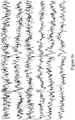
- the present invention is further capable to separate the artifact 18 relating to the sensor 14d, and remove it from the magnetic field signal measured by sensor 14d. This is performed by the algorithm disclosed above in detail, run by the processor in the MEG measurement device 19. The results with much better S/N ratio can be seen in Figure 3 .
- Figure 2 illustrates a flow chart of the method according to an example of the invention.
- the measurement arrangement is set up, by putting a measurement helmet comprising sensors around the patient's head, for example.
- the arrangement comprises 306 measurement sensors.
- the raw signal is recorded 21.
- an n-dimensional "magnetic subspace" following SSS analysis according to prior art is set up 22.
- the SSS method separates the interesting magnetic sources from the interfering magnetic sources, the first ones locating inside the measurement helmet, and the others clearly outside the measurement helmet, usually outside the measurement room, too.
- the number of magnetic field shapes representing the interesting signals is in one example 80, and the number of magnetic field shapes representing the interferences signals is 15, for instance. Therefore, the subspace 22 is in this example a 95*306 matrix representing all signals originating from magnetic sources.
- the artifact analysis of the invention is started by forming a combined basis by adding m vectors of type (0, 0, 0,..., 1, 0, 0,..., 0) T to the n-dimensional subspace in order to model artifacts and independent channel noise 23.
- the combination is made according to equation 4.
- the recorded N-dimensional signal is decomposed into n+m components in the combined basis. Finally, the components corresponding to the m added vectors are subtracted from the raw signal 25.
- FIGs 3a and 3b illustrate two seconds of data from an MEG recording of human somatosensory response. Signals from six MEG channels are shown. The y-scale of the figures is illustrated by a vertical segment of a line whose length in this case is 200 fT/cm. In Figure 3a , there is the original recorded raw data. In Figure 3b , the same signals after processing the data with the method of the present invention are illustrated. The two somatosensory responses, simultaneously seen in five of the six channels, are clearly seen in the processed data. Only the sensor noise intrinsic to each channel has been removed in this case. The reduction in random sensor noise is about a factor of five. Most of the variation of the signals outside of the somatosensory response periods is from ongoing spontaneous brain activity independent from the somatosensory stimulus.
- the present invention can even be applied in analyzing Gallup results of different kinds of polls where gathered results represent the opinions otherwise realistically, but there are some peculiar results which can be clearly regarded as not real opinions. Such opinions can be regarded as artifacts which need to be cleared from the results in order to achieve much more reliable poll result.
- sensors with higher noise characteristics may be used.
- superconductors applied in higher temperatures may be used in the used sensor technology. This releaves the requirements of cooling of the sensors, because higher temperatures are possible.
- the most important advantage of the present invention is that the artifactual noise in the set of measurement channels can be clearly reduced, improving the overall quality in analyzing the biomagnetic signals.
- the presented method is broadly applicable in many different applications, comprising multichannel magnetoencephalography, electroencephalography and magnetic resonance imaging measurements.
- the steps of the method presented for the invention can be carried out in applicable parts as a computer program that can be run on the data processing logic of the MEG device, the EEG device or the MRI device i.e. typically on the processor of the device.
- the device may include a memory or other storage medium wherein the computer program, the data input and other parameters required by the method and the results obtained from the measurements can be stored.
Landscapes
- Physics & Mathematics (AREA)
- Health & Medical Sciences (AREA)
- Life Sciences & Earth Sciences (AREA)
- Engineering & Computer Science (AREA)
- General Physics & Mathematics (AREA)
- Signal Processing (AREA)
- Condensed Matter Physics & Semiconductors (AREA)
- General Health & Medical Sciences (AREA)
- Pathology (AREA)
- Public Health (AREA)
- Veterinary Medicine (AREA)
- Biomedical Technology (AREA)
- Heart & Thoracic Surgery (AREA)
- Medical Informatics (AREA)
- Molecular Biology (AREA)
- Surgery (AREA)
- Animal Behavior & Ethology (AREA)
- Biophysics (AREA)
- Artificial Intelligence (AREA)
- Physiology (AREA)
- Computer Vision & Pattern Recognition (AREA)
- Psychiatry (AREA)
- Nuclear Medicine, Radiotherapy & Molecular Imaging (AREA)
- Radiology & Medical Imaging (AREA)
- High Energy & Nuclear Physics (AREA)
- Neurology (AREA)
- Measurement And Recording Of Electrical Phenomena And Electrical Characteristics Of The Living Body (AREA)
- Magnetic Resonance Imaging Apparatus (AREA)
Applications Claiming Priority (2)
| Application Number | Priority Date | Filing Date | Title |
|---|---|---|---|
| FI20125075A FI125397B (fi) | 2012-01-24 | 2012-01-24 | Menetelmä spatiaalisen ja temporaalisen ylinäytteityksen käyttämiseksi monikanavaisissa mittauksissa |
| PCT/IB2013/050595 WO2013111072A1 (en) | 2012-01-24 | 2013-01-24 | Method and device for recognizing and removing undesired artifacts in multichannel magnetic field or electric potential measurements |
Publications (3)
| Publication Number | Publication Date |
|---|---|
| EP2806789A1 EP2806789A1 (en) | 2014-12-03 |
| EP2806789A4 EP2806789A4 (en) | 2015-10-21 |
| EP2806789B1 true EP2806789B1 (en) | 2017-08-30 |
Family
ID=48872936
Family Applications (1)
| Application Number | Title | Priority Date | Filing Date |
|---|---|---|---|
| EP13740539.5A Active EP2806789B1 (en) | 2012-01-24 | 2013-01-24 | Method and device for recognizing and removing undesired artifacts in multichannel magnetic field or electric potential measurements |
Country Status (6)
| Country | Link |
|---|---|
| US (1) | US10307105B2 (fi) |
| EP (1) | EP2806789B1 (fi) |
| JP (1) | JP6143794B2 (fi) |
| CA (1) | CA2862189C (fi) |
| FI (1) | FI125397B (fi) |
| WO (1) | WO2013111072A1 (fi) |
Families Citing this family (23)
| Publication number | Priority date | Publication date | Assignee | Title |
|---|---|---|---|---|
| US8593141B1 (en) | 2009-11-24 | 2013-11-26 | Hypres, Inc. | Magnetic resonance system and method employing a digital squid |
| US8970217B1 (en) | 2010-04-14 | 2015-03-03 | Hypres, Inc. | System and method for noise reduction in magnetic resonance imaging |
| FI125397B (fi) | 2012-01-24 | 2015-09-30 | Elekta Ab | Menetelmä spatiaalisen ja temporaalisen ylinäytteityksen käyttämiseksi monikanavaisissa mittauksissa |
| BR112017004336A2 (pt) | 2014-09-05 | 2017-12-05 | Hyperfine Res Inc | métodos e aparelhos de formação de imagem por ressonância magnética de campo baixo |
| WO2017205734A1 (en) * | 2016-05-26 | 2017-11-30 | University Of Washington | Reducing sensor noise in multichannel arrays using oversampled temporal projection and associated systems and methods |
| US10627464B2 (en) | 2016-11-22 | 2020-04-21 | Hyperfine Research, Inc. | Low-field magnetic resonance imaging methods and apparatus |
| WO2018098141A1 (en) | 2016-11-22 | 2018-05-31 | Hyperfine Research, Inc. | Systems and methods for automated detection in magnetic resonance images |
| WO2019060298A1 (en) | 2017-09-19 | 2019-03-28 | Neuroenhancement Lab, LLC | METHOD AND APPARATUS FOR NEURO-ACTIVATION |
| US11717686B2 (en) | 2017-12-04 | 2023-08-08 | Neuroenhancement Lab, LLC | Method and apparatus for neuroenhancement to facilitate learning and performance |
| US11318277B2 (en) | 2017-12-31 | 2022-05-03 | Neuroenhancement Lab, LLC | Method and apparatus for neuroenhancement to enhance emotional response |
| US12280219B2 (en) | 2017-12-31 | 2025-04-22 | NeuroLight, Inc. | Method and apparatus for neuroenhancement to enhance emotional response |
| US11364361B2 (en) | 2018-04-20 | 2022-06-21 | Neuroenhancement Lab, LLC | System and method for inducing sleep by transplanting mental states |
| WO2020032998A1 (en) * | 2018-08-06 | 2020-02-13 | Hi Llc | Systems and methods to reduce data and complexity in neural signal processing chain |
| JP6664568B1 (ja) | 2018-08-22 | 2020-03-13 | 旭化成エレクトロニクス株式会社 | 磁場計測装置、磁場計測方法、磁場計測プログラム |
| US12336821B2 (en) | 2018-08-24 | 2025-06-24 | University Of Washington | Apparatuses, systems, and methods for suppression of artifacts in non-invasive electromagnetic recordings |
| CN113382683A (zh) | 2018-09-14 | 2021-09-10 | 纽罗因恒思蒙特实验有限责任公司 | 改善睡眠的系统和方法 |
| JP6936405B2 (ja) | 2018-12-26 | 2021-09-15 | 旭化成エレクトロニクス株式会社 | 磁場計測装置 |
| US11497425B2 (en) | 2019-03-08 | 2022-11-15 | Asahi Kasei Microdevices Corporation | Magnetic field measurement apparatus |
| US11701042B2 (en) | 2019-03-14 | 2023-07-18 | Ricoh Company, Ltd. | Signal processing apparatus and signal processing method |
| US11786694B2 (en) | 2019-05-24 | 2023-10-17 | NeuroLight, Inc. | Device, method, and app for facilitating sleep |
| US11768258B2 (en) | 2019-11-27 | 2023-09-26 | Ricoh Company, Ltd. | Signal separating apparatus, signal separating method, and non-transitory recording medium |
| JP7626622B2 (ja) | 2021-01-20 | 2025-02-04 | 旭化成エレクトロニクス株式会社 | 磁場計測装置、磁場計測方法、磁場計測プログラム |
| CN114384463B (zh) * | 2022-01-13 | 2024-10-29 | 中国电子科技集团公司第五十四研究所 | 一种基于空间投影的伪信源辨识方法 |
Family Cites Families (6)
| Publication number | Priority date | Publication date | Assignee | Title |
|---|---|---|---|---|
| IL163669A0 (en) | 2002-02-06 | 2005-12-18 | Univ California | Squid detected nmr and mri at ultralow fields |
| FI115324B (fi) * | 2003-03-14 | 2005-04-15 | Elekta Neuromag Oy | Menetelmä ja järjestelmä monikanavaisen mittaussignaalin käsittelemiseksi |
| FI115737B (fi) | 2003-09-26 | 2005-06-30 | Elekta Neuromag Oy | Menetelmä monikanavaisen mittaussignaalin käyttämiseksi lähdemallinnuksessa |
| JP5361131B2 (ja) | 2007-01-03 | 2013-12-04 | エレクタ アクチボラゲット | 直交仮想チャネルを使用したマルチチャネル測定データの分析 |
| FI124427B (fi) * | 2010-07-06 | 2014-08-29 | Elekta Ab | Menetelmä häiriöavaruuden tarkentamiseksi biomagneettisissa kenttämittauksissa |
| FI125397B (fi) | 2012-01-24 | 2015-09-30 | Elekta Ab | Menetelmä spatiaalisen ja temporaalisen ylinäytteityksen käyttämiseksi monikanavaisissa mittauksissa |
-
2012
- 2012-01-24 FI FI20125075A patent/FI125397B/fi active IP Right Grant
-
2013
- 2013-01-24 WO PCT/IB2013/050595 patent/WO2013111072A1/en not_active Ceased
- 2013-01-24 CA CA2862189A patent/CA2862189C/en active Active
- 2013-01-24 US US14/374,365 patent/US10307105B2/en active Active
- 2013-01-24 JP JP2014553840A patent/JP6143794B2/ja active Active
- 2013-01-24 EP EP13740539.5A patent/EP2806789B1/en active Active
Non-Patent Citations (1)
| Title |
|---|
| None * |
Also Published As
| Publication number | Publication date |
|---|---|
| JP2015508318A (ja) | 2015-03-19 |
| EP2806789A4 (en) | 2015-10-21 |
| JP6143794B2 (ja) | 2017-06-07 |
| FI125397B (fi) | 2015-09-30 |
| WO2013111072A1 (en) | 2013-08-01 |
| CA2862189C (en) | 2018-09-11 |
| US10307105B2 (en) | 2019-06-04 |
| US20140343882A1 (en) | 2014-11-20 |
| FI20125075A7 (fi) | 2013-07-25 |
| EP2806789A1 (en) | 2014-12-03 |
| CA2862189A1 (en) | 2013-08-01 |
Similar Documents
| Publication | Publication Date | Title |
|---|---|---|
| US10307105B2 (en) | Method and device for recognizing and removing undesired artifacts in multichannel magnetic field or electric potential measurements | |
| EP1880226B1 (en) | Method and device for interference suppression in electromagnetic multi-channel measurement | |
| US11160509B2 (en) | Methods and systems of de-noising magnetic-field based sensor data of electrophysiological signals | |
| US20160051162A1 (en) | Method for locating a brain activity associated with a task | |
| US7729740B2 (en) | Noise cancellation in magnetoencephalography and electroencephalography with isolated reference sensors | |
| US11540778B2 (en) | Reducing sensor noise in multichannel arrays using oversampled temporal projection and associated systems and methods | |
| US20160051161A1 (en) | Method for locating a brain activity associated with a task | |
| US20140107464A1 (en) | Method for Locating a Brain Activity | |
| Giraldo-Suarez et al. | Reconstruction of neural activity from EEG data using dynamic spatiotemporal constraints | |
| WO2021075548A1 (ja) | 脳状態推定装置、コンピュータプログラム、脳状態推定方法、脳機能の検査システムおよび方法 | |
| Nolte et al. | The effect of artifact rejection by signal-space projection on source localization accuracy in MEG measurements | |
| US11213255B2 (en) | Information processing device, information processing method, and recording medium storing information processing program | |
| Long et al. | State-space solutions to the dynamic magnetoencephalography inverse problem using high performance computing | |
| JP2024147676A (ja) | 非侵襲的電磁記録におけるアーチファクトを抑制するための装置、システム、および方法 | |
| EP1998668B1 (en) | Method and apparatus for localising and displaying electrophysiological signals | |
| US11768258B2 (en) | Signal separating apparatus, signal separating method, and non-transitory recording medium | |
| Darvas et al. | Functional imaging of brain activity and connectivity with MEG | |
| Lamus et al. | An analysis of how spatiotemporal dynamic models of brain activity could improve MEG/EEG inverse solutions | |
| Pfeiffer et al. | Sensor localization using magnetic dipole-like coils: A method for highly accurate co-registration in on-scalp MEG | |
| Hasson et al. | A Bayesian test for the appropriateness of a model in the biomagnetic inverse problem | |
| Rajakenttä | Robustness of hidden Markov hodels for detecting resting beta states in magnetoencephalography data | |
| Jokivuolle | Including head movement in magnetoencephalographic source estimation | |
| Luan | Analysis of Neuroelectromagnetic Problems via Subspace Decomposition Imaging and Inverse Algorithm | |
| Sekihara et al. | Electromagnetic brain imaging | |
| Sun | Simultaneous recording of EEG and fMRI: New approach to remove gradient and ballistocardiogram EEG-artifacts |
Legal Events
| Date | Code | Title | Description |
|---|---|---|---|
| PUAI | Public reference made under article 153(3) epc to a published international application that has entered the european phase |
Free format text: ORIGINAL CODE: 0009012 |
|
| 17P | Request for examination filed |
Effective date: 20140821 |
|
| AK | Designated contracting states |
Kind code of ref document: A1 Designated state(s): AL AT BE BG CH CY CZ DE DK EE ES FI FR GB GR HR HU IE IS IT LI LT LU LV MC MK MT NL NO PL PT RO RS SE SI SK SM TR |
|
| DAX | Request for extension of the european patent (deleted) | ||
| RA4 | Supplementary search report drawn up and despatched (corrected) |
Effective date: 20150923 |
|
| RIC1 | Information provided on ipc code assigned before grant |
Ipc: G01R 33/035 20060101ALI20150917BHEP Ipc: A61B 5/04 20060101AFI20150917BHEP |
|
| GRAP | Despatch of communication of intention to grant a patent |
Free format text: ORIGINAL CODE: EPIDOSNIGR1 |
|
| INTG | Intention to grant announced |
Effective date: 20170413 |
|
| GRAS | Grant fee paid |
Free format text: ORIGINAL CODE: EPIDOSNIGR3 |
|
| GRAA | (expected) grant |
Free format text: ORIGINAL CODE: 0009210 |
|
| GRAT | Correction requested after decision to grant or after decision to maintain patent in amended form |
Free format text: ORIGINAL CODE: EPIDOSNCDEC |
|
| AK | Designated contracting states |
Kind code of ref document: B1 Designated state(s): AL AT BE BG CH CY CZ DE DK EE ES FI FR GB GR HR HU IE IS IT LI LT LU LV MC MK MT NL NO PL PT RO RS SE SI SK SM TR |
|
| REG | Reference to a national code |
Ref country code: GB Ref legal event code: FG4D |
|
| REG | Reference to a national code |
Ref country code: CH Ref legal event code: EP |
|
| REG | Reference to a national code |
Ref country code: AT Ref legal event code: REF Ref document number: 922740 Country of ref document: AT Kind code of ref document: T Effective date: 20170915 |
|
| REG | Reference to a national code |
Ref country code: IE Ref legal event code: FG4D |
|
| REG | Reference to a national code |
Ref country code: DE Ref legal event code: R096 Ref document number: 602013025797 Country of ref document: DE |
|
| REG | Reference to a national code |
Ref country code: NL Ref legal event code: FP |
|
| REG | Reference to a national code |
Ref country code: LT Ref legal event code: MG4D |
|
| REG | Reference to a national code |
Ref country code: AT Ref legal event code: MK05 Ref document number: 922740 Country of ref document: AT Kind code of ref document: T Effective date: 20170830 |
|
| REG | Reference to a national code |
Ref country code: FR Ref legal event code: PLFP Year of fee payment: 6 |
|
| PG25 | Lapsed in a contracting state [announced via postgrant information from national office to epo] |
Ref country code: LT Free format text: LAPSE BECAUSE OF FAILURE TO SUBMIT A TRANSLATION OF THE DESCRIPTION OR TO PAY THE FEE WITHIN THE PRESCRIBED TIME-LIMIT Effective date: 20170830 Ref country code: FI Free format text: LAPSE BECAUSE OF FAILURE TO SUBMIT A TRANSLATION OF THE DESCRIPTION OR TO PAY THE FEE WITHIN THE PRESCRIBED TIME-LIMIT Effective date: 20170830 Ref country code: SE Free format text: LAPSE BECAUSE OF FAILURE TO SUBMIT A TRANSLATION OF THE DESCRIPTION OR TO PAY THE FEE WITHIN THE PRESCRIBED TIME-LIMIT Effective date: 20170830 Ref country code: AT Free format text: LAPSE BECAUSE OF FAILURE TO SUBMIT A TRANSLATION OF THE DESCRIPTION OR TO PAY THE FEE WITHIN THE PRESCRIBED TIME-LIMIT Effective date: 20170830 Ref country code: NO Free format text: LAPSE BECAUSE OF FAILURE TO SUBMIT A TRANSLATION OF THE DESCRIPTION OR TO PAY THE FEE WITHIN THE PRESCRIBED TIME-LIMIT Effective date: 20171130 Ref country code: HR Free format text: LAPSE BECAUSE OF FAILURE TO SUBMIT A TRANSLATION OF THE DESCRIPTION OR TO PAY THE FEE WITHIN THE PRESCRIBED TIME-LIMIT Effective date: 20170830 |
|
| PG25 | Lapsed in a contracting state [announced via postgrant information from national office to epo] |
Ref country code: LV Free format text: LAPSE BECAUSE OF FAILURE TO SUBMIT A TRANSLATION OF THE DESCRIPTION OR TO PAY THE FEE WITHIN THE PRESCRIBED TIME-LIMIT Effective date: 20170830 Ref country code: GR Free format text: LAPSE BECAUSE OF FAILURE TO SUBMIT A TRANSLATION OF THE DESCRIPTION OR TO PAY THE FEE WITHIN THE PRESCRIBED TIME-LIMIT Effective date: 20171201 Ref country code: RS Free format text: LAPSE BECAUSE OF FAILURE TO SUBMIT A TRANSLATION OF THE DESCRIPTION OR TO PAY THE FEE WITHIN THE PRESCRIBED TIME-LIMIT Effective date: 20170830 Ref country code: ES Free format text: LAPSE BECAUSE OF FAILURE TO SUBMIT A TRANSLATION OF THE DESCRIPTION OR TO PAY THE FEE WITHIN THE PRESCRIBED TIME-LIMIT Effective date: 20170830 Ref country code: BG Free format text: LAPSE BECAUSE OF FAILURE TO SUBMIT A TRANSLATION OF THE DESCRIPTION OR TO PAY THE FEE WITHIN THE PRESCRIBED TIME-LIMIT Effective date: 20171130 Ref country code: IS Free format text: LAPSE BECAUSE OF FAILURE TO SUBMIT A TRANSLATION OF THE DESCRIPTION OR TO PAY THE FEE WITHIN THE PRESCRIBED TIME-LIMIT Effective date: 20171230 |
|
| PG25 | Lapsed in a contracting state [announced via postgrant information from national office to epo] |
Ref country code: CZ Free format text: LAPSE BECAUSE OF FAILURE TO SUBMIT A TRANSLATION OF THE DESCRIPTION OR TO PAY THE FEE WITHIN THE PRESCRIBED TIME-LIMIT Effective date: 20170830 Ref country code: PL Free format text: LAPSE BECAUSE OF FAILURE TO SUBMIT A TRANSLATION OF THE DESCRIPTION OR TO PAY THE FEE WITHIN THE PRESCRIBED TIME-LIMIT Effective date: 20170830 Ref country code: DK Free format text: LAPSE BECAUSE OF FAILURE TO SUBMIT A TRANSLATION OF THE DESCRIPTION OR TO PAY THE FEE WITHIN THE PRESCRIBED TIME-LIMIT Effective date: 20170830 Ref country code: RO Free format text: LAPSE BECAUSE OF FAILURE TO SUBMIT A TRANSLATION OF THE DESCRIPTION OR TO PAY THE FEE WITHIN THE PRESCRIBED TIME-LIMIT Effective date: 20170830 |
|
| PG25 | Lapsed in a contracting state [announced via postgrant information from national office to epo] |
Ref country code: SM Free format text: LAPSE BECAUSE OF FAILURE TO SUBMIT A TRANSLATION OF THE DESCRIPTION OR TO PAY THE FEE WITHIN THE PRESCRIBED TIME-LIMIT Effective date: 20170830 Ref country code: EE Free format text: LAPSE BECAUSE OF FAILURE TO SUBMIT A TRANSLATION OF THE DESCRIPTION OR TO PAY THE FEE WITHIN THE PRESCRIBED TIME-LIMIT Effective date: 20170830 Ref country code: SK Free format text: LAPSE BECAUSE OF FAILURE TO SUBMIT A TRANSLATION OF THE DESCRIPTION OR TO PAY THE FEE WITHIN THE PRESCRIBED TIME-LIMIT Effective date: 20170830 |
|
| REG | Reference to a national code |
Ref country code: DE Ref legal event code: R097 Ref document number: 602013025797 Country of ref document: DE |
|
| PLBE | No opposition filed within time limit |
Free format text: ORIGINAL CODE: 0009261 |
|
| STAA | Information on the status of an ep patent application or granted ep patent |
Free format text: STATUS: NO OPPOSITION FILED WITHIN TIME LIMIT |
|
| 26N | No opposition filed |
Effective date: 20180531 |
|
| PG25 | Lapsed in a contracting state [announced via postgrant information from national office to epo] |
Ref country code: SI Free format text: LAPSE BECAUSE OF FAILURE TO SUBMIT A TRANSLATION OF THE DESCRIPTION OR TO PAY THE FEE WITHIN THE PRESCRIBED TIME-LIMIT Effective date: 20170830 |
|
| REG | Reference to a national code |
Ref country code: CH Ref legal event code: PL |
|
| PG25 | Lapsed in a contracting state [announced via postgrant information from national office to epo] |
Ref country code: LU Free format text: LAPSE BECAUSE OF NON-PAYMENT OF DUE FEES Effective date: 20180124 |
|
| REG | Reference to a national code |
Ref country code: IE Ref legal event code: MM4A |
|
| REG | Reference to a national code |
Ref country code: BE Ref legal event code: MM Effective date: 20180131 |
|
| PG25 | Lapsed in a contracting state [announced via postgrant information from national office to epo] |
Ref country code: CH Free format text: LAPSE BECAUSE OF NON-PAYMENT OF DUE FEES Effective date: 20180131 Ref country code: BE Free format text: LAPSE BECAUSE OF NON-PAYMENT OF DUE FEES Effective date: 20180131 Ref country code: LI Free format text: LAPSE BECAUSE OF NON-PAYMENT OF DUE FEES Effective date: 20180131 |
|
| PG25 | Lapsed in a contracting state [announced via postgrant information from national office to epo] |
Ref country code: IE Free format text: LAPSE BECAUSE OF NON-PAYMENT OF DUE FEES Effective date: 20180124 |
|
| PG25 | Lapsed in a contracting state [announced via postgrant information from national office to epo] |
Ref country code: MC Free format text: LAPSE BECAUSE OF FAILURE TO SUBMIT A TRANSLATION OF THE DESCRIPTION OR TO PAY THE FEE WITHIN THE PRESCRIBED TIME-LIMIT Effective date: 20170830 |
|
| REG | Reference to a national code |
Ref country code: NL Ref legal event code: HC Owner name: MEGIN OY; FI Free format text: DETAILS ASSIGNMENT: CHANGE OF OWNER(S), CHANGE OF OWNER(S) NAME; FORMER OWNER NAME: ELEKTA OY Effective date: 20190627 Ref country code: NL Ref legal event code: PD Owner name: ELEKTA OY; FI Free format text: DETAILS ASSIGNMENT: CHANGE OF OWNER(S), ASSIGNMENT; FORMER OWNER NAME: ELEKTA AB (PUBL). Effective date: 20190627 |
|
| REG | Reference to a national code |
Ref country code: GB Ref legal event code: 732E Free format text: REGISTERED BETWEEN 20190718 AND 20190724 |
|
| REG | Reference to a national code |
Ref country code: DE Ref legal event code: R082 Ref document number: 602013025797 Country of ref document: DE Representative=s name: PATENTANWAELTE SAMSON & PARTNER, DE Ref country code: DE Ref legal event code: R081 Ref document number: 602013025797 Country of ref document: DE Owner name: ELEKTRA OY, FI Free format text: FORMER OWNER: ELEKTA AB (PUBL), STOCKHOLM, SE Ref country code: DE Ref legal event code: R081 Ref document number: 602013025797 Country of ref document: DE Owner name: MEGIN OY, FI Free format text: FORMER OWNER: ELEKTA AB (PUBL), STOCKHOLM, SE |
|
| REG | Reference to a national code |
Ref country code: DE Ref legal event code: R082 Ref document number: 602013025797 Country of ref document: DE Representative=s name: PATENTANWAELTE SAMSON & PARTNER, DE Ref country code: DE Ref legal event code: R081 Ref document number: 602013025797 Country of ref document: DE Owner name: MEGIN OY, FI Free format text: FORMER OWNER: ELEKTRA OY, HELSINKI, FI |
|
| PG25 | Lapsed in a contracting state [announced via postgrant information from national office to epo] |
Ref country code: MT Free format text: LAPSE BECAUSE OF NON-PAYMENT OF DUE FEES Effective date: 20180124 |
|
| PG25 | Lapsed in a contracting state [announced via postgrant information from national office to epo] |
Ref country code: TR Free format text: LAPSE BECAUSE OF FAILURE TO SUBMIT A TRANSLATION OF THE DESCRIPTION OR TO PAY THE FEE WITHIN THE PRESCRIBED TIME-LIMIT Effective date: 20170830 |
|
| PG25 | Lapsed in a contracting state [announced via postgrant information from national office to epo] |
Ref country code: PT Free format text: LAPSE BECAUSE OF FAILURE TO SUBMIT A TRANSLATION OF THE DESCRIPTION OR TO PAY THE FEE WITHIN THE PRESCRIBED TIME-LIMIT Effective date: 20170830 Ref country code: HU Free format text: LAPSE BECAUSE OF FAILURE TO SUBMIT A TRANSLATION OF THE DESCRIPTION OR TO PAY THE FEE WITHIN THE PRESCRIBED TIME-LIMIT; INVALID AB INITIO Effective date: 20130124 |
|
| PG25 | Lapsed in a contracting state [announced via postgrant information from national office to epo] |
Ref country code: CY Free format text: LAPSE BECAUSE OF FAILURE TO SUBMIT A TRANSLATION OF THE DESCRIPTION OR TO PAY THE FEE WITHIN THE PRESCRIBED TIME-LIMIT Effective date: 20170830 Ref country code: MK Free format text: LAPSE BECAUSE OF NON-PAYMENT OF DUE FEES Effective date: 20170830 |
|
| PG25 | Lapsed in a contracting state [announced via postgrant information from national office to epo] |
Ref country code: AL Free format text: LAPSE BECAUSE OF FAILURE TO SUBMIT A TRANSLATION OF THE DESCRIPTION OR TO PAY THE FEE WITHIN THE PRESCRIBED TIME-LIMIT Effective date: 20170830 |
|
| REG | Reference to a national code |
Ref country code: DE Ref legal event code: R079 Ref document number: 602013025797 Country of ref document: DE Free format text: PREVIOUS MAIN CLASS: A61B0005040000 Ipc: A61B0005240000 |
|
| PGFP | Annual fee paid to national office [announced via postgrant information from national office to epo] |
Ref country code: NL Payment date: 20250127 Year of fee payment: 13 |
|
| PGFP | Annual fee paid to national office [announced via postgrant information from national office to epo] |
Ref country code: DE Payment date: 20250121 Year of fee payment: 13 |
|
| PGFP | Annual fee paid to national office [announced via postgrant information from national office to epo] |
Ref country code: FR Payment date: 20250117 Year of fee payment: 13 |
|
| PGFP | Annual fee paid to national office [announced via postgrant information from national office to epo] |
Ref country code: IT Payment date: 20250123 Year of fee payment: 13 Ref country code: GB Payment date: 20250121 Year of fee payment: 13 |