EP2806515A2 - Raceway assembly for conductor cables, raceway and retainer suitable for being part of said assembly - Google Patents
Raceway assembly for conductor cables, raceway and retainer suitable for being part of said assembly Download PDFInfo
- Publication number
- EP2806515A2 EP2806515A2 EP14168858.0A EP14168858A EP2806515A2 EP 2806515 A2 EP2806515 A2 EP 2806515A2 EP 14168858 A EP14168858 A EP 14168858A EP 2806515 A2 EP2806515 A2 EP 2806515A2
- Authority
- EP
- European Patent Office
- Prior art keywords
- raceway
- retainer
- vertical
- tab
- section
- Prior art date
- Legal status (The legal status is an assumption and is not a legal conclusion. Google has not performed a legal analysis and makes no representation as to the accuracy of the status listed.)
- Granted
Links
Images


Classifications
-
- H—ELECTRICITY
- H02—GENERATION; CONVERSION OR DISTRIBUTION OF ELECTRIC POWER
- H02G—INSTALLATION OF ELECTRIC CABLES OR LINES, OR OF COMBINED OPTICAL AND ELECTRIC CABLES OR LINES
- H02G3/00—Installations of electric cables or lines or protective tubing therefor in or on buildings, equivalent structures or vehicles
- H02G3/02—Details
- H02G3/04—Protective tubing or conduits, e.g. cable ladders or cable troughs
- H02G3/0406—Details thereof
- H02G3/0418—Covers or lids; Their fastenings
Definitions
- the invention relates to a raceway assembly for conductor cables, such as for example electrical cables or fiber optic cables, of the type comprising a raceway with a rectangular-shaped cross-section formed by a horizontal base and two vertical side walls demarcating between one another an open upper face of said raceway, each of said side walls being provided at the upper end thereof with a support configuration for fixing retainers; and at least one retainer formed by a rigid oblong part which detachably snaps at its ends onto said supports of the side walls, such that said retainer thus fixed is arranged in a bridge position, forming a rigid bridge between the upper ends of said side walls of the raceway.
- the invention also relates to a raceway and to a retainer suitable for being part of said assembly.
- raceway assemblies in the past, described in documents ES2014604A6 and ES1067776U . Although these devices satisfactorily comply with their function, they can be improved. It has particularly been observed (on rare occasions) that installers can accidentally hit one of the retainers fixed in the raceway hard enough to release it, so the installers have to then get it back. It has also been observed that when the raceway is subjected to considerable bending due to the load subjected thereto (the weight of the conductor cables themselves, the weight of the snow built up on the raceway cover, etc.), there is a risk that said bending will cause one of the retainers and/or the raceway cover to be released. The maximum distance between raceway supports is limited to avoid this risk.
- the purpose of the invention is to provide a raceway assembly of the type indicated above based on the earlier developments described in the mentioned documents ES2014604A6 and ES1067776U , and in which the fixing of the retainer in the raceway is more robust.
- Another objective of the invention consists of making the retainers provide greater stiffness to the raceway in a robust manner.
- Another additional objective is to make the operations that installers must perform easier, particularly while the retainer is not arranged in the final bridge position.
- the raceway is characterized in that the support configuration provided at the upper end of the side walls of the raceway comprises an oblique section of the side wall extending towards the central plane of the raceway, a vertical upper leg originating from said oblique section, and there being formed at the end of said oblique section a right angle profile with a vertical wing extending towards the base of the raceway and a horizontal wing extending back towards said vertical upper leg without actually reaching it, such that between said vertical upper leg and the end of said horizontal wing of the right angle profile there is defined an opening towards a cavity demarcated by said oblique section, said vertical upper leg and said horizontal wing.
- the retainer in turn, is characterized in that it is provided at each of its ends with at least one elbow-shaped upper tab, having a first horizontal section prolonged by a vertical end section, and at least one lower tab.
- the upper tab and lower tab of the retainer are sized so that when said retainer is arranged in the bridge position, the first horizontal section of said upper tab is supported on the upper portion of the horizontal wing of the right angle profile, and the vertical end section of said vertical tab is introduced in the cavity through the opening and supported against the vertical upper leg, whereas said lower tab is supported on the lower portion of the oblique section.
- This solution according to the invention differs from devices of the prior art, particularly, in that the support configuration provided at the upper end of the side walls of the raceway has an opening towards a cavity in which the vertical end section of the upper tab provided at the end of the retainer is introduced. This provides very firm fixing of the end of the retainer in the support configuration.
- the upper tab and the lower tab are sized so that when said retainer is arranged in an intermediate inclined position, in which said retainer extends in an inclined direction with respect to the horizontal base of the raceway and is coupled at only one of its ends to one of said support configurations of a side wall of the raceway, the other end of said retainer being in a raised position, said lower tab of the retainer is supported on the outer portion of said vertical wing of the right angle profile, whereas the vertical end section of said upper tab of the retainer is obliquely introduced in the cavity through the opening and is supported on one or several of the walls demarcating said cavity, exerting a force keeping said retainer in said intermediate inclined position.
- the installers can place the retainer in this intermediate inclined position, which the retainer can hold by itself, and gradually lay the conductor cables inside the raceway without the retainer arranged in that position getting in the way of performing this task.
- the lower tab of the retainer preferably comprises at its end a tooth forming an inclined surface such that when said retainer is arranged in the bridge position, said lower tab is supported on the lower portion of the oblique section through said inclined surface of the tooth, which is parallel to the face of said oblique section on which it is supported, and when said retainer is arranged in the intermediate inclined position, said lower tab is supported on the outer portion of said vertical wing of the right angle profile through said inclined surface of the tooth, which is parallel to the face of the vertical wing on which it is supported.
- This configuration offers, on one hand, a very robust fixing of the retainer in the bridge position, and on the other hand, good retainer stability in the intermediate inclined position.
- the retainer is provided on at least one of its longitudinal sides with a hook configured for detachably snap fastening said retainer to one of said support configurations of a side wall of the raceway, such that said retainer thus fastened by means of said hook is arranged in a stand-by position, in which said retainer extends longitudinally inside said raceway next to said side wall, said hook being provided with a curved end that is introduced in the opening defined between the vertical upper leg and the end of the horizontal wing of the right angle profile.
- This solution allows comfortably placing the retainer inside the raceway such that it is properly fastened and does not get in the way, which facilitates assembly packaging and transport to the points where it will be installed, and it also facilitates the operations of the installers who have to work with the assembly. It will be seen that this latter solution, which consists of incorporating a hook on a longitudinal side of the retainer, is itself an invention that is linked to the configuration of the raceway defined in the main claim, but not necessarily to the configuration of the retainer, in relation to the upper tab and lower tab, defined in said claim.
- the hook preferably has a shape complementary to the shape of the right angle profile formed at the end of said oblique section.
- the raceway preferably comprises on at least one of its side walls a vertical lower leg extending from the oblique section towards the base of the raceway, said vertical lower leg being positioned such that when the retainer is arranged in the stand-by position, a portion of said retainer is supported against said vertical lower leg. A particularly robust fixing of the retainer in the stand-by position is thus obtained.
- the vertical wing of the right angle profile extends towards the base of the raceway, forming a lower projection with respect to the oblique section
- the retainer comprises on the side provided with the hook at least one claw arranged such that when said retainer is arranged in the stand-by position, said claw fits in the corner formed between said lower projection and said oblique section.
- the retainer is formed by a plurality of detachable portions distributed in the longitudinal direction of said retainer, said detachable portions being provided at their ends with catch-like portions on the lower face of the retainer.
- Configuring the retainer in detachable portions, as described in the mentioned documents ES2014604A6 and ES1067776U , for the purpose of being able to use the retainer as a bridge between the side wall of the raceway and an intermediate partition placed in the raceway is known.
- the improvement introduced by the present invention consists of the detachable portions being attached to one another by side walls of the retainer in which there are through slots extending from the upper face of the retainer towards the lower edge of the side walls of the retainer, but without actually reaching said lower edge.
- the side walls of the retainer are split into sections, corresponding to the detachable portions, which are separated from one another by the through slots but attached by a bridge formed between the end of said slot and the lower edge.
- the catch-like portions are preferably arranged such that one end of one of said detachable portions has a pair of said catch-like portions which are separated from one another forming a fork, whereas the corresponding end of another one of said detachable portions, adjacent to the former, has a single one of said catch-like portions fitted in said fork formed by said pair of catch-like portions.
- This configuration is known and described in the mentioned documents ES2014604A6 and ES1067776U .
- the improvement according to the present invention consists of providing transverse breakable bridges attaching said single catch-like portion to said pair of catch-like portions, and furthermore, preferably, longitudinal breakable bridges attaching said single catch-like portion to the end of the adjacent detachable portion. The stiffness of the retainer is even further increased as a result of these transverse and longitudinal bridges.
- the raceway 1 depicted in Figures 1 and 2 is a profile made from extruded thermoplastic.
- This raceway 1 has a cross-section shape which is common in raceways used for conductor cables: a horizontal base 2 and two vertical side walls 3 demarcating between one another an open upper face 4.
- the raceway 1 is characterized by the particular shape of the support configuration 5 at the upper end of each of the side walls 3 of the raceway 1, which serves for fixing a retainer 6 custom-designed for this raceway 1.
- the retainer 6 can be fixed in a bridge position ( Figure 4 ), in an intermediate inclined position ( Figure 3 ), or in a stand-by position ( Figures 5-6 ).
- This particular shape of the support configuration 5 (see Figure 2 ) consists of comprising an oblique section 7 of the side wall 3 of the raceway 1 extending towards the central plane of said raceway 1, a vertical upper leg 8 originating from said oblique section 7, and there being formed at the end of said oblique section 7 a right angle profile 9 with a vertical wing 10 extending towards the base 2 of the raceway and a horizontal wing 11 extending back towards said vertical upper leg 8 without actually reaching it, such that between said vertical upper leg 8 and the end of said horizontal wing 11 of the right angle profile 9 there is defined an opening 12 towards a cavity 13 demarcated by said oblique section 7, said vertical upper leg 8 and said horizontal wing 11. Furthermore, the vertical wing 10 of the right angle profile 9 extends towards the base 2 of the raceway forming a lower projection 18 with respect to said oblique section 7.
- the retainer 6 is formed by a rigid oblong part made of molded thermoplastic, and its main purpose consists, in a known manner, of detachably snapping at its ends onto support configurations 5 provided in the side walls 3 of the raceway 1.
- the retainer 6 thus fixed is arranged in a bridge position such as that shown in Figure 4 , forming a rigid bridge between the upper ends of the side walls 3 of the raceway 1.
- the retainer 6 has two main particularities which are independent from one another, but each of which is related to the particular shape of the support configuration 5 in the raceway.
- a first particularity which allows arranging the retainer 6 in the bridge position ( Figure 4 ) obtaining a particularly robust fixing, consists of said retainer 6 being provided at each of its ends with at least one elbow-shaped upper tab 14, having a first horizontal section 14a prolonged by a vertical end section 14b, and at least one lower tab 15.
- the retainer 6 comprises at each of its ends two upper tabs 14 separated from one another and a single lower tab 15 located in the center with respect to said two upper tabs 14.
- the upper tab 14 and lower tab 15 are sized such that when the retainer 6 is arranged in the bridge position, the first horizontal section 14a of the upper tab 14 is supported on the upper portion of the horizontal wing 11 of the right angle profile 9, the vertical end section 14b of the vertical tab 14 is introduced in the cavity 13 through the opening 12 and is supported against the vertical upper leg 8, and the lower tab 15 is supported on the lower portion of the oblique section 7.
- the sizing of the upper tab 14 and lower tab 15 is such that when the retainer is arranged in the intermediate inclined position shown in Figure 3 , in which said retainer 6 extends in an inclined direction with respect to the horizontal base 2 of the raceway and is coupled at only one of its ends to one of the support configurations 5 of a side wall 3 of the raceway 1, the other end of the retainer 6 being in a raised position, said lower tab 15 is supported on the outer portion of the vertical wing 10 of the right angle profile 9, whereas the vertical end section 14b of said upper tab 14 is obliquely introduced in the cavity 13 through the opening 12 and is supported on one or several of the walls demarcating said cavity 13, thus exerting a force keeping the retainer 6 in the intermediate inclined position.
- the lower tab 15 of the retainer 6 comprises at its end a tooth 28 forming an inclined surface 29 such that when the retainer 6 is arranged in the bridge position, as shown in Figure 4 , said lower tab 15 is supported on the lower portion of the oblique section 7 through the inclined surface 29 of the tooth 28, which is parallel to the face of the oblique section 7 on which it is supported; and when the retainer 6 is arranged in the intermediate inclined position shown in Figure 3 , said lower tab 15 is supported on the outer portion of the vertical wing 10 of the right angle profile 9 through said inclined surface 29 of the tooth 28, which is parallel to the face of said vertical wing 10 on which it is supported.
- a second particularity which allows arranging the retainer 6 in the stand-by position shown in Figures 5-6 , consists of the retainer 6 being provided on at least one of its longitudinal sides with a hook 16 configured for detachably snap fastening said retainer 6 to one of the support configurations 5 of one of the side walls 3 of the raceway 1.
- the retainer 6 thus fastened by means of the hook 16 is arranged in the mentioned stand-by position ( Figures 5-6 ), in which said retainer 6 extends longitudinally inside the raceway 1 next to the side wall 3 thereof.
- the retainer 6 comprises on the side provided with the hook 16 at least one claw 19 arranged such that when said retainer 6 is arranged in the stand-by position ( Figures 5-6 ), said claw 19 fits in the corner formed between the lower projection 18 and the oblique section 7.
- the hook 16 has a shape complementary to the shape of the right angle profile 9 formed at the end of said oblique section 7: said hook 16 has a first straight section 16a extending in the transverse direction of the retainer 6, a second straight section 16b orthogonal to the first, and a curved end 16c which is introduced in the opening 12 defined between the vertical upper leg 8 and the end of the horizontal wing 11 of the right angle profile 9.
- the retainer 6 is formed in a known manner by a plurality of detachable portions 20 which are distributed in the longitudinal direction of said retainer 6 and are provided at their ends with catch-like portions 21, 22 on the lower face of said retainer 6.
- these catch-like portions 21, 22 are arranged such that one end of one of the detachable portions 20 has a pair of catch-like portions 21 separated from one another forming a fork, whereas the corresponding end of another one of the detachable portions 20, adjacent to the former, has a single catch-like portion 22 fitted in said fork formed by the pair of catch-like portions 21.
- these catch-like portions 21, 22 are intended for being coupled on the upper edge of an intermediate partition (not depicted in the drawings of the present document).
- the originality of the invention consists of improvements which seek to make the retainer 6 more rigid.
- the detachable portions 20 are attached to one another by side walls 23 of the retainer 6 in which there are through slots 24 extending from the upper face of said retainer 6 towards the lower edge 25 of said side walls 23 without actually reaching said lower edge 25.
- Transverse breakable bridges 26 attaching the single catch-like portion 22 to the pair of corresponding catch-like portions 21 are also provided.
- Longitudinal breakable bridges 27 attaching the single catch-like portion 22 to the end of the adjacent detachable portion 20 are also provided.
Abstract
Description
- The invention relates to a raceway assembly for conductor cables, such as for example electrical cables or fiber optic cables, of the type comprising a raceway with a rectangular-shaped cross-section formed by a horizontal base and two vertical side walls demarcating between one another an open upper face of said raceway, each of said side walls being provided at the upper end thereof with a support configuration for fixing retainers; and at least one retainer formed by a rigid oblong part which detachably snaps at its ends onto said supports of the side walls, such that said retainer thus fixed is arranged in a bridge position, forming a rigid bridge between the upper ends of said side walls of the raceway.
- The invention also relates to a raceway and to a retainer suitable for being part of said assembly.
- The applicant has developed such raceway assemblies in the past, described in documents
ES2014604A6 ES1067776U - The purpose of the invention is to provide a raceway assembly of the type indicated above based on the earlier developments described in the mentioned documents
ES2014604A6 ES1067776U - Another objective of the invention consists of making the retainers provide greater stiffness to the raceway in a robust manner.
- Another additional objective is to make the operations that installers must perform easier, particularly while the retainer is not arranged in the final bridge position.
- This is achieved by means of a raceway assembly for conductor cables of the type indicated above, according to
claim 1. In this assembly, the raceway is characterized in that the support configuration provided at the upper end of the side walls of the raceway comprises an oblique section of the side wall extending towards the central plane of the raceway, a vertical upper leg originating from said oblique section, and there being formed at the end of said oblique section a right angle profile with a vertical wing extending towards the base of the raceway and a horizontal wing extending back towards said vertical upper leg without actually reaching it, such that between said vertical upper leg and the end of said horizontal wing of the right angle profile there is defined an opening towards a cavity demarcated by said oblique section, said vertical upper leg and said horizontal wing. The retainer, in turn, is characterized in that it is provided at each of its ends with at least one elbow-shaped upper tab, having a first horizontal section prolonged by a vertical end section, and at least one lower tab. The upper tab and lower tab of the retainer are sized so that when said retainer is arranged in the bridge position, the first horizontal section of said upper tab is supported on the upper portion of the horizontal wing of the right angle profile, and the vertical end section of said vertical tab is introduced in the cavity through the opening and supported against the vertical upper leg, whereas said lower tab is supported on the lower portion of the oblique section. - This solution according to the invention differs from devices of the prior art, particularly, in that the support configuration provided at the upper end of the side walls of the raceway has an opening towards a cavity in which the vertical end section of the upper tab provided at the end of the retainer is introduced. This provides very firm fixing of the end of the retainer in the support configuration.
- Based on the invention defined in the main claim, preferred embodiments the features of which are described in the dependent claims have been provided.
- Preferably, in the retainer the upper tab and the lower tab are sized so that when said retainer is arranged in an intermediate inclined position, in which said retainer extends in an inclined direction with respect to the horizontal base of the raceway and is coupled at only one of its ends to one of said support configurations of a side wall of the raceway, the other end of said retainer being in a raised position, said lower tab of the retainer is supported on the outer portion of said vertical wing of the right angle profile, whereas the vertical end section of said upper tab of the retainer is obliquely introduced in the cavity through the opening and is supported on one or several of the walls demarcating said cavity, exerting a force keeping said retainer in said intermediate inclined position. The installers can place the retainer in this intermediate inclined position, which the retainer can hold by itself, and gradually lay the conductor cables inside the raceway without the retainer arranged in that position getting in the way of performing this task.
- Furthermore, the lower tab of the retainer preferably comprises at its end a tooth forming an inclined surface such that when said retainer is arranged in the bridge position, said lower tab is supported on the lower portion of the oblique section through said inclined surface of the tooth, which is parallel to the face of said oblique section on which it is supported, and when said retainer is arranged in the intermediate inclined position, said lower tab is supported on the outer portion of said vertical wing of the right angle profile through said inclined surface of the tooth, which is parallel to the face of the vertical wing on which it is supported. This configuration offers, on one hand, a very robust fixing of the retainer in the bridge position, and on the other hand, good retainer stability in the intermediate inclined position.
- In several advantageous embodiments, the retainer is provided on at least one of its longitudinal sides with a hook configured for detachably snap fastening said retainer to one of said support configurations of a side wall of the raceway, such that said retainer thus fastened by means of said hook is arranged in a stand-by position, in which said retainer extends longitudinally inside said raceway next to said side wall, said hook being provided with a curved end that is introduced in the opening defined between the vertical upper leg and the end of the horizontal wing of the right angle profile. This solution allows comfortably placing the retainer inside the raceway such that it is properly fastened and does not get in the way, which facilitates assembly packaging and transport to the points where it will be installed, and it also facilitates the operations of the installers who have to work with the assembly. It will be seen that this latter solution, which consists of incorporating a hook on a longitudinal side of the retainer, is itself an invention that is linked to the configuration of the raceway defined in the main claim, but not necessarily to the configuration of the retainer, in relation to the upper tab and lower tab, defined in said claim.
- The hook preferably has a shape complementary to the shape of the right angle profile formed at the end of said oblique section. This solution provides a robust fixing of the retainer in the stand-by position.
- The raceway preferably comprises on at least one of its side walls a vertical lower leg extending from the oblique section towards the base of the raceway, said vertical lower leg being positioned such that when the retainer is arranged in the stand-by position, a portion of said retainer is supported against said vertical lower leg. A particularly robust fixing of the retainer in the stand-by position is thus obtained.
- Preferably, in the raceway the vertical wing of the right angle profile extends towards the base of the raceway, forming a lower projection with respect to the oblique section, and the retainer comprises on the side provided with the hook at least one claw arranged such that when said retainer is arranged in the stand-by position, said claw fits in the corner formed between said lower projection and said oblique section. This solution even further increases the robustness of the fixing of the retainer in the stand-by position.
- In advantageous embodiments, the retainer is formed by a plurality of detachable portions distributed in the longitudinal direction of said retainer, said detachable portions being provided at their ends with catch-like portions on the lower face of the retainer. Configuring the retainer in detachable portions, as described in the mentioned documents
ES2014604A6 ES1067776U - The catch-like portions are preferably arranged such that one end of one of said detachable portions has a pair of said catch-like portions which are separated from one another forming a fork, whereas the corresponding end of another one of said detachable portions, adjacent to the former, has a single one of said catch-like portions fitted in said fork formed by said pair of catch-like portions. This configuration is known and described in the mentioned documents
ES2014604A6 ES1067776U - The invention also comprises other detail features illustrated in the following description of an embodiment of the invention and in the attached drawings.
- The advantages and features of the invention will be understood from the following description in which a preferred embodiment of the invention is described in relation to the drawings with a non-limiting character with respect to the scope of the main claim.
-
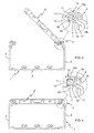
Figure 1 is a front view of the raceway. -
Figure 2 is an enlarged partial view of the support configuration at the upper end of the side walls of the raceway. -
Figures 3 and 4 are front views showing the retainer arranged in the raceway in the intermediate inclined position (Figure 3 ) and in the bridge position, respectively. -
Figures 5 and 6 are a perspective view and a partial front view, respectively, showing the retainer arranged in the raceway in the stand-by position. -
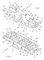
Figures 7, 8 ,9 and 10 are a top perspective view, a bottom perspective view, a side view and a top plan view, respectively, of the retainer. - The
raceway 1 depicted inFigures 1 and 2 is a profile made from extruded thermoplastic. Thisraceway 1 has a cross-section shape which is common in raceways used for conductor cables: ahorizontal base 2 and twovertical side walls 3 demarcating between one another an openupper face 4. There is formed at the upper end of the side walls 3 alip 30 which allows fixing a cover (not depicted) for closing the openupper face 4 of the raceway. There are formed at thebase 2 of theraceway feet 31 which allow installing longitudinal intermediate partitions (not depicted) used to compartmentalize theraceway 1. All this is known and described, for example, in the mentioned documentsES2014604A6 ES1067776U - The
raceway 1 according to the invention is characterized by the particular shape of thesupport configuration 5 at the upper end of each of theside walls 3 of theraceway 1, which serves for fixing aretainer 6 custom-designed for thisraceway 1. Theretainer 6 can be fixed in a bridge position (Figure 4 ), in an intermediate inclined position (Figure 3 ), or in a stand-by position (Figures 5-6 ). - This particular shape of the support configuration 5 (see
Figure 2 ) consists of comprising anoblique section 7 of theside wall 3 of theraceway 1 extending towards the central plane of saidraceway 1, a verticalupper leg 8 originating from saidoblique section 7, and there being formed at the end of said oblique section 7 aright angle profile 9 with avertical wing 10 extending towards thebase 2 of the raceway and ahorizontal wing 11 extending back towards said verticalupper leg 8 without actually reaching it, such that between said verticalupper leg 8 and the end of saidhorizontal wing 11 of theright angle profile 9 there is defined anopening 12 towards acavity 13 demarcated by saidoblique section 7, said verticalupper leg 8 and saidhorizontal wing 11. Furthermore, thevertical wing 10 of theright angle profile 9 extends towards thebase 2 of the raceway forming alower projection 18 with respect to saidoblique section 7. - The
retainer 6 is formed by a rigid oblong part made of molded thermoplastic, and its main purpose consists, in a known manner, of detachably snapping at its ends ontosupport configurations 5 provided in theside walls 3 of theraceway 1. Theretainer 6 thus fixed is arranged in a bridge position such as that shown inFigure 4 , forming a rigid bridge between the upper ends of theside walls 3 of theraceway 1. According to the invention, theretainer 6 has two main particularities which are independent from one another, but each of which is related to the particular shape of thesupport configuration 5 in the raceway. - A first particularity, which allows arranging the
retainer 6 in the bridge position (Figure 4 ) obtaining a particularly robust fixing, consists of saidretainer 6 being provided at each of its ends with at least one elbow-shapedupper tab 14, having a firsthorizontal section 14a prolonged by avertical end section 14b, and at least onelower tab 15. In the depicted embodiment, theretainer 6 comprises at each of its ends twoupper tabs 14 separated from one another and a singlelower tab 15 located in the center with respect to said twoupper tabs 14. As can be seen particularly inFigure 4 , theupper tab 14 andlower tab 15 are sized such that when theretainer 6 is arranged in the bridge position, the firsthorizontal section 14a of theupper tab 14 is supported on the upper portion of thehorizontal wing 11 of theright angle profile 9, thevertical end section 14b of thevertical tab 14 is introduced in thecavity 13 through theopening 12 and is supported against the verticalupper leg 8, and thelower tab 15 is supported on the lower portion of theoblique section 7. - Furthermore, for the purpose of helping the installers with the tasks of laying conductor cables in the
raceway 1, the sizing of theupper tab 14 andlower tab 15 is such that when the retainer is arranged in the intermediate inclined position shown inFigure 3 , in which saidretainer 6 extends in an inclined direction with respect to thehorizontal base 2 of the raceway and is coupled at only one of its ends to one of thesupport configurations 5 of aside wall 3 of theraceway 1, the other end of theretainer 6 being in a raised position, saidlower tab 15 is supported on the outer portion of thevertical wing 10 of theright angle profile 9, whereas thevertical end section 14b of saidupper tab 14 is obliquely introduced in thecavity 13 through theopening 12 and is supported on one or several of the walls demarcating saidcavity 13, thus exerting a force keeping theretainer 6 in the intermediate inclined position. - On the other hand, the
lower tab 15 of theretainer 6 comprises at its end atooth 28 forming aninclined surface 29 such that when theretainer 6 is arranged in the bridge position, as shown inFigure 4 , saidlower tab 15 is supported on the lower portion of theoblique section 7 through theinclined surface 29 of thetooth 28, which is parallel to the face of theoblique section 7 on which it is supported; and when theretainer 6 is arranged in the intermediate inclined position shown inFigure 3 , saidlower tab 15 is supported on the outer portion of thevertical wing 10 of theright angle profile 9 through saidinclined surface 29 of thetooth 28, which is parallel to the face of saidvertical wing 10 on which it is supported. - A second particularity, which allows arranging the
retainer 6 in the stand-by position shown inFigures 5-6 , consists of theretainer 6 being provided on at least one of its longitudinal sides with ahook 16 configured for detachably snap fastening saidretainer 6 to one of thesupport configurations 5 of one of theside walls 3 of theraceway 1. Theretainer 6 thus fastened by means of thehook 16 is arranged in the mentioned stand-by position (Figures 5-6 ), in which saidretainer 6 extends longitudinally inside theraceway 1 next to theside wall 3 thereof. Furthermore, as can be seen inFigures 7-10 , theretainer 6 comprises on the side provided with thehook 16 at least oneclaw 19 arranged such that when saidretainer 6 is arranged in the stand-by position (Figures 5-6 ), saidclaw 19 fits in the corner formed between thelower projection 18 and theoblique section 7. In the embodiment depicted in the drawings, there are twoclaws 19 and thehook 16 is arranged in the centered position with respect to these twoclaws 19. - As can be seen in
Figure 6 , thehook 16 has a shape complementary to the shape of theright angle profile 9 formed at the end of said oblique section 7: saidhook 16 has a firststraight section 16a extending in the transverse direction of theretainer 6, a secondstraight section 16b orthogonal to the first, and acurved end 16c which is introduced in theopening 12 defined between the verticalupper leg 8 and the end of thehorizontal wing 11 of theright angle profile 9. - On the other hand, as can also be seen in
Figure 6 , when theretainer 6 is arranged in the stand-by position, a portion thereof is supported against a verticallower leg 17 of theraceway 1, extending from theoblique section 7 towards thebase 2 of saidraceway 1. - In the preferred embodiments, such as that depicted in the drawings, the
retainer 6 is formed in a known manner by a plurality ofdetachable portions 20 which are distributed in the longitudinal direction of saidretainer 6 and are provided at their ends with catch-like portions retainer 6. As can be seen inFigures 7, 8 and10 , these catch-like portions detachable portions 20 has a pair of catch-like portions 21 separated from one another forming a fork, whereas the corresponding end of another one of thedetachable portions 20, adjacent to the former, has a single catch-like portion 22 fitted in said fork formed by the pair of catch-like portions 21. As shown in the mentioned documentsES2014604A6 ES1067776U like portions retainer 6 more rigid. To that end, thedetachable portions 20 are attached to one another byside walls 23 of theretainer 6 in which there are throughslots 24 extending from the upper face of saidretainer 6 towards thelower edge 25 of saidside walls 23 without actually reaching saidlower edge 25. Transversebreakable bridges 26 attaching the single catch-like portion 22 to the pair of corresponding catch-like portions 21 are also provided. Longitudinalbreakable bridges 27 attaching the single catch-like portion 22 to the end of the adjacentdetachable portion 20 are also provided.
Claims (14)
- A raceway assembly for conductor cables, comprising a raceway (1) with a rectangular-shaped cross-section formed by a horizontal base (2) and two vertical side walls (3) demarcating between one another an open upper face (4) of said raceway (1), each of said side walls (3) being provided at the upper end thereof with a support configuration (5) for fixing retainers (6); and at least one retainer (6) formed by a rigid oblong part which detachably snaps at its ends onto said support configurations (5) of the side walls (3), such that said retainer (6) thus fixed is arranged in a bridge position, forming a rigid bridge between the upper ends of said side walls (3) of the raceway (1); characterized in that said support configuration (5) comprises an oblique section (7) of said side wall (3) extending towards the central plane of said raceway (1), a vertical upper leg (8) originating from said oblique section (7), and there being formed at the end of said oblique section (7) a right angle profile (9) with a vertical wing (10) extending towards the base (2) of the raceway (1) and a horizontal wing (11) extending back towards said vertical upper leg (8) without actually reaching it, such that between said vertical upper leg (8) and the end of said horizontal wing (11) of the right angle profile (9) there is defined an opening (12) towards a cavity (13) demarcated by said oblique section (7), said vertical upper leg (8) and said horizontal wing (11), and in that said at least one retainer (6) is provided at each of its ends with at least one elbow-shaped upper tab (14), having a first horizontal section (14a) prolonged by a vertical end section (14b) and at least one lower tab (15), said upper tab (14) and lower tab (15) of the retainer (6) being sized so that when said retainer (6) is arranged in said bridge position, said first horizontal section (14a) of the upper tab (14) is supported on the upper portion of said horizontal wing (11) of the right angle profile (9) and said vertical end section (14b) of the vertical tab (14) is introduced in said cavity (13) through said opening (12) and supported against said vertical upper leg (8), whereas said lower tab (15) is supported on the lower portion of said oblique section (7).
- The raceway assembly for conductor cables according to claim 1, characterized in that in said retainer (6), said upper tab (14) and said lower tab (15) are sized so that when said retainer is arranged in an intermediate inclined position, in which said retainer (6) extends in an inclined direction with respect to the horizontal base (2) of the raceway (1) and is coupled at only one of its ends to one of said support configurations (5) of a side wall (3) of the raceway (1), the other end of said retainer (6) being in the raised position, said lower tab (15) of the retainer (6) is supported on the outer portion of said vertical wing (10) of the right angle profile (9), whereas said vertical end section (14b) of the upper tab (14) of the retainer (6) is obliquely introduced in said cavity (13) through said opening (12) and is supported on one or several of the walls demarcating said cavity (13), exerting a force keeping said retainer (6) in said intermediate inclined position.
- The raceway assembly for conductor cables according to claim 2, characterized in that in said retainer (6), said lower tab (15) comprises at its end a tooth (28) forming an inclined surface (29) such that when said retainer (6) is arranged in said bridge position, said lower tab (15) is supported on the lower portion of said oblique section (7) through said inclined surface (29) of the tooth (28), which is parallel to the face of said oblique section (7) on which it is supported, and when said retainer (6) is arranged in said intermediate inclined position, said lower tab (15) is supported on the outer portion of said vertical wing (10) of the right angle profile (9) through said inclined surface (29) of the tooth (28), which is parallel to the face of said vertical wing (10) on which it is supported.
- The raceway assembly for conductor cables according to any of claims 1 to 3, characterized in that said retainer (6) is provided on at least one of its longitudinal sides with a hook (16) configured for detachably snap fastening said retainer (6) to one of said support configurations (5) of a side wall (3) of the raceway (1), such that said retainer (6) thus fastened by means of said hook (16) is arranged in a stand-by position, in which said retainer (6) extends longitudinally inside said raceway (1) next to said side wall (3), said hook (16) being provided with a curved end (16c) that is introduced in said opening (12) defined between said vertical upper leg (8) and the end of said horizontal wing (11) of the right angle profile (9).
- The raceway assembly according to claim 4, characterized in that said hook (16) has a shape complementary to the shape of said right angle profile (9) formed at the end of said oblique section (7).
- The raceway assembly according to claim 4 or 5, characterized in that on at least one of said side walls (3) said raceway (1) comprises a vertical lower leg (17) extending from said oblique section (7) towards said base (2) of the raceway (1), said vertical lower leg (17) being positioned such that when said retainer (6) is arranged in said stand-by position, a portion of said retainer (6) is supported against said vertical lower leg (17).
- The raceway assembly according to any of claims 4 to 6, characterized in that in the raceway (1) said vertical wing (10) of the right angle profile (9) extends towards said base (2) of the raceway (1) forming a lower projection (18) with respect to said oblique section (7), and in that the retainer (6) comprises on the side provided with said hook (16) at least one claw (19) arranged such that when said retainer (6) is arranged in said stand-by position, said claw (19) fits in the corner formed between said lower projection (18) and said oblique section (7).
- A raceway (1) suitable for forming the raceway (1) of the raceway assembly for conductor cables according to claim 1, said raceway (1) having a rectangular-shaped cross-section and being formed by a horizontal base (2) and two vertical side walls (3) demarcating between one another an open upper face (4) of said raceway (1), each of said side walls (3) being provided at the upper end thereof with a support configuration (5) for fixing retainers (6), said raceway (1) being characterized in that said support configuration (5) comprises an oblique section (7) of said side wall (3) extending towards the central plane of said raceway (1), a vertical upper leg (8) originating from said oblique section (7), and there being formed at the end of said oblique section (7) a right angle profile (9) with a vertical wing (10) extending towards the base (2) of the raceway (1) and a horizontal wing (11) extending back towards said vertical upper leg (8) without actually reaching it, such that between said vertical upper leg (8) and the end of said horizontal wing (11) of the right angle profile (9) there is defined an opening (12) towards a cavity (13) demarcated by said oblique section (7), said vertical upper leg (8) and said horizontal wing (11).
- The raceway (1) according to claim 8, characterized in that it comprises in at least one of said side walls (3) a vertical lower leg (17) extending from said oblique section (7) towards said base (2) of the raceway (1).
- The raceway according to any of claims 8 or 9, characterized in that said vertical wing (10) of the right angle profile (9) extends towards said base (2) of the raceway (1) forming a lower projection (18) with respect to said oblique section (7).
- A retainer (6) suitable for forming the retainer (6) of the raceway assembly for conductor cables according to claim 1, said retainer (6) being formed by a rigid oblong part and being characterized in that it is provided at each of its ends with at least one elbow-shaped upper tab (14), having a first horizontal section (14a) prolonged by a vertical end section (14b), and at least one lower tab (15).
- The retainer according to claim 11, characterized in that said lower tab (15) comprises at its end a tooth (28) forming an inclined surface (29).
- The retainer according to any of claims 11 or 12, characterized in that it comprises a hook (16) provided with a curved end (16c) on at least one of its longitudinal sides.
- The retainer according to claim 13, characterized in that it comprises at least one claw (19) on the side provided with said hook (16).
Applications Claiming Priority (1)
| Application Number | Priority Date | Filing Date | Title |
|---|---|---|---|
| ES201330620U ES1081179Y (en) | 2013-05-21 | 2013-05-21 | "Channel set for conductive cables" |
Publications (3)
| Publication Number | Publication Date |
|---|---|
| EP2806515A2 true EP2806515A2 (en) | 2014-11-26 |
| EP2806515A3 EP2806515A3 (en) | 2015-04-29 |
| EP2806515B1 EP2806515B1 (en) | 2016-08-03 |
Family
ID=48485684
Family Applications (1)
| Application Number | Title | Priority Date | Filing Date |
|---|---|---|---|
| EP14168858.0A Active EP2806515B1 (en) | 2013-05-21 | 2014-05-19 | Raceway assembly for conductor cables, raceway and retainer suitable for being part of said assembly |
Country Status (4)
| Country | Link |
|---|---|
| EP (1) | EP2806515B1 (en) |
| ES (2) | ES1081179Y (en) |
| PL (1) | PL2806515T3 (en) |
| PT (1) | PT2806515T (en) |
Cited By (6)
| Publication number | Priority date | Publication date | Assignee | Title |
|---|---|---|---|---|
| CN107769120A (en) * | 2017-12-06 | 2018-03-06 | 江苏艮德电力设备有限公司 | A kind of reinforced capping cable testing bridge |
| CN107785832A (en) * | 2017-12-06 | 2018-03-09 | 江苏艮德电力设备有限公司 | One kind capping cable testing bridge |
| CN107834463A (en) * | 2017-12-06 | 2018-03-23 | 江苏艮德电力设备有限公司 | A kind of reinforced capping adjustable cable crane span structure |
| CN107959267A (en) * | 2017-12-06 | 2018-04-24 | 江苏艮德电力设备有限公司 | A kind of reinforced adjustable cable crane span structure |
| CN108054697A (en) * | 2017-12-06 | 2018-05-18 | 江苏艮德电力设备有限公司 | A kind of adjustable subregion cable testing bridge |
| JP2020044992A (en) * | 2018-09-19 | 2020-03-26 | 本田技研工業株式会社 | vehicle |
Citations (2)
| Publication number | Priority date | Publication date | Assignee | Title |
|---|---|---|---|---|
| ES2014604A6 (en) | 1989-04-14 | 1990-07-16 | Aparellaje Electrico Sa | Device for stiffening of cable channels or ducts for electrical conductors or similar and corresponding clamps. |
| ES1067776U (en) | 2008-04-28 | 2008-06-16 | Unex Aparellaje Electrico S.L. | Retainer of electrical conductors covered by channels (Machine-translation by Google Translate, not legally binding) |
Family Cites Families (6)
| Publication number | Priority date | Publication date | Assignee | Title |
|---|---|---|---|---|
| US5942729A (en) * | 1997-08-04 | 1999-08-24 | The Siemon Company | Double hinged raceway |
| CA2348220A1 (en) * | 2000-05-26 | 2001-11-26 | Hubbell Incorporated | Hinged raceway with latch |
| US6437244B1 (en) * | 2000-06-05 | 2002-08-20 | Panduit Corp. | Wiring duct system hinge arrangement |
| US6903265B1 (en) * | 2004-05-27 | 2005-06-07 | Panduit Corp. | Hinged and latched raceway |
| ITMI20050647A1 (en) * | 2005-04-14 | 2006-10-15 | Canalplast S P A | DUCT STRUCTURE EQUIPPED WITH AN ANTI-SLIP COVER TO CONTAIN PIPE AND SIMILAR CABLES |
| EP2112732A1 (en) * | 2008-04-25 | 2009-10-28 | Unex Aparellaje Electrico S.L. | Raceway for electrical conductors and retainer applicable to said raceway |
-
2013
- 2013-05-21 ES ES201330620U patent/ES1081179Y/en not_active Expired - Fee Related
-
2014
- 2014-05-19 PT PT141688580T patent/PT2806515T/en unknown
- 2014-05-19 PL PL14168858T patent/PL2806515T3/en unknown
- 2014-05-19 ES ES14168858.0T patent/ES2600140T3/en active Active
- 2014-05-19 EP EP14168858.0A patent/EP2806515B1/en active Active
Patent Citations (2)
| Publication number | Priority date | Publication date | Assignee | Title |
|---|---|---|---|---|
| ES2014604A6 (en) | 1989-04-14 | 1990-07-16 | Aparellaje Electrico Sa | Device for stiffening of cable channels or ducts for electrical conductors or similar and corresponding clamps. |
| ES1067776U (en) | 2008-04-28 | 2008-06-16 | Unex Aparellaje Electrico S.L. | Retainer of electrical conductors covered by channels (Machine-translation by Google Translate, not legally binding) |
Cited By (8)
| Publication number | Priority date | Publication date | Assignee | Title |
|---|---|---|---|---|
| CN107769120A (en) * | 2017-12-06 | 2018-03-06 | 江苏艮德电力设备有限公司 | A kind of reinforced capping cable testing bridge |
| CN107785832A (en) * | 2017-12-06 | 2018-03-09 | 江苏艮德电力设备有限公司 | One kind capping cable testing bridge |
| CN107834463A (en) * | 2017-12-06 | 2018-03-23 | 江苏艮德电力设备有限公司 | A kind of reinforced capping adjustable cable crane span structure |
| CN107959267A (en) * | 2017-12-06 | 2018-04-24 | 江苏艮德电力设备有限公司 | A kind of reinforced adjustable cable crane span structure |
| CN108054697A (en) * | 2017-12-06 | 2018-05-18 | 江苏艮德电力设备有限公司 | A kind of adjustable subregion cable testing bridge |
| CN107785832B (en) * | 2017-12-06 | 2018-11-23 | 唐山市致胜商务信息咨询有限公司 | A kind of capping cable testing bridge |
| JP2020044992A (en) * | 2018-09-19 | 2020-03-26 | 本田技研工業株式会社 | vehicle |
| US11376948B2 (en) | 2018-09-19 | 2022-07-05 | Honda Motor Co., Ltd. | Vehicle |
Also Published As
| Publication number | Publication date |
|---|---|
| ES1081179Y (en) | 2013-08-30 |
| ES2600140T3 (en) | 2017-02-07 |
| ES1081179U (en) | 2013-06-05 |
| EP2806515B1 (en) | 2016-08-03 |
| PL2806515T3 (en) | 2017-01-31 |
| EP2806515A3 (en) | 2015-04-29 |
| PT2806515T (en) | 2016-11-14 |
Similar Documents
| Publication | Publication Date | Title |
|---|---|---|
| EP2806515B1 (en) | Raceway assembly for conductor cables, raceway and retainer suitable for being part of said assembly | |
| EP3066398B1 (en) | Carrier structure for solar panels and method of producing such a carrier structure | |
| AU2019202881B2 (en) | Decking or flooring system, and components therefor | |
| US20150076291A1 (en) | Accessory Section for a Cable Tray System | |
| US9670674B2 (en) | Clip assembly for a suspended ceiling | |
| US7544893B2 (en) | Extruded wire duct end cap | |
| US9112340B2 (en) | Side wall bracket for cable tray | |
| JP2017531137A (en) | Guidance device | |
| US20220320842A1 (en) | Flexible channel molding assemblies | |
| RU2658952C2 (en) | Connecting element with profiled rails | |
| EP2374954B1 (en) | Section for structures and relative structure | |
| EP3469166B1 (en) | Wall cladding | |
| ATE358755T1 (en) | BANDRASTER SYSTEM | |
| CN111527657B (en) | Cable reel assembly | |
| TW201522751A (en) | Section with lip and tongues and associated spacer | |
| EP3066731B1 (en) | Multi-directional cable route | |
| US9145986B2 (en) | Wiring support for aircraft | |
| JP2013023917A (en) | Parting member set and construction method of the same | |
| US11261601B2 (en) | Cross runner connector and cross runner connector arrangement for a suspended ceiling system | |
| JP5666516B2 (en) | How to form and remove partition walls | |
| JP2015148327A (en) | Decorative cover and protection cover arrangement structure | |
| EP3291392B1 (en) | Cable tray | |
| JP7070877B2 (en) | Construction method of corner members and wallpaper | |
| AU2018204298B2 (en) | Housing for an electrical fitting in a sliding door unit | |
| SE529802C2 (en) | entrance flange |
Legal Events
| Date | Code | Title | Description |
|---|---|---|---|
| PUAI | Public reference made under article 153(3) epc to a published international application that has entered the european phase |
Free format text: ORIGINAL CODE: 0009012 |
|
| 17P | Request for examination filed |
Effective date: 20140519 |
|
| AK | Designated contracting states |
Kind code of ref document: A2 Designated state(s): AL AT BE BG CH CY CZ DE DK EE ES FI FR GB GR HR HU IE IS IT LI LT LU LV MC MK MT NL NO PL PT RO RS SE SI SK SM TR |
|
| AX | Request for extension of the european patent |
Extension state: BA ME |
|
| PUAL | Search report despatched |
Free format text: ORIGINAL CODE: 0009013 |
|
| AK | Designated contracting states |
Kind code of ref document: A3 Designated state(s): AL AT BE BG CH CY CZ DE DK EE ES FI FR GB GR HR HU IE IS IT LI LT LU LV MC MK MT NL NO PL PT RO RS SE SI SK SM TR |
|
| AX | Request for extension of the european patent |
Extension state: BA ME |
|
| RIC1 | Information provided on ipc code assigned before grant |
Ipc: H02G 3/04 20060101AFI20150320BHEP |
|
| R17P | Request for examination filed (corrected) |
Effective date: 20151015 |
|
| RBV | Designated contracting states (corrected) |
Designated state(s): AL AT BE BG CH CY CZ DE DK EE ES FI FR GB GR HR HU IE IS IT LI LT LU LV MC MK MT NL NO PL PT RO RS SE SI SK SM TR |
|
| GRAP | Despatch of communication of intention to grant a patent |
Free format text: ORIGINAL CODE: EPIDOSNIGR1 |
|
| INTG | Intention to grant announced |
Effective date: 20160413 |
|
| GRAS | Grant fee paid |
Free format text: ORIGINAL CODE: EPIDOSNIGR3 |
|
| GRAA | (expected) grant |
Free format text: ORIGINAL CODE: 0009210 |
|
| AK | Designated contracting states |
Kind code of ref document: B1 Designated state(s): AL AT BE BG CH CY CZ DE DK EE ES FI FR GB GR HR HU IE IS IT LI LT LU LV MC MK MT NL NO PL PT RO RS SE SI SK SM TR |
|
| REG | Reference to a national code |
Ref country code: GB Ref legal event code: FG4D |
|
| REG | Reference to a national code |
Ref country code: CH Ref legal event code: EP Ref country code: AT Ref legal event code: REF Ref document number: 817885 Country of ref document: AT Kind code of ref document: T Effective date: 20160815 |
|
| REG | Reference to a national code |
Ref country code: IE Ref legal event code: FG4D |
|
| REG | Reference to a national code |
Ref country code: DE Ref legal event code: R096 Ref document number: 602014002945 Country of ref document: DE |
|
| REG | Reference to a national code |
Ref country code: CH Ref legal event code: NV Representative=s name: FIAMMENGHI-FIAMMENGHI, CH |
|
| REG | Reference to a national code |
Ref country code: NL Ref legal event code: FP |
|
| REG | Reference to a national code |
Ref country code: PT Ref legal event code: SC4A Ref document number: 2806515 Country of ref document: PT Date of ref document: 20161114 Kind code of ref document: T Free format text: AVAILABILITY OF NATIONAL TRANSLATION Effective date: 20161031 |
|
| REG | Reference to a national code |
Ref country code: SE Ref legal event code: TRGR |
|
| REG | Reference to a national code |
Ref country code: LT Ref legal event code: MG4D |
|
| PG25 | Lapsed in a contracting state [announced via postgrant information from national office to epo] |
Ref country code: NO Free format text: LAPSE BECAUSE OF FAILURE TO SUBMIT A TRANSLATION OF THE DESCRIPTION OR TO PAY THE FEE WITHIN THE PRESCRIBED TIME-LIMIT Effective date: 20161103 Ref country code: IS Free format text: LAPSE BECAUSE OF FAILURE TO SUBMIT A TRANSLATION OF THE DESCRIPTION OR TO PAY THE FEE WITHIN THE PRESCRIBED TIME-LIMIT Effective date: 20161203 Ref country code: LT Free format text: LAPSE BECAUSE OF FAILURE TO SUBMIT A TRANSLATION OF THE DESCRIPTION OR TO PAY THE FEE WITHIN THE PRESCRIBED TIME-LIMIT Effective date: 20160803 Ref country code: FI Free format text: LAPSE BECAUSE OF FAILURE TO SUBMIT A TRANSLATION OF THE DESCRIPTION OR TO PAY THE FEE WITHIN THE PRESCRIBED TIME-LIMIT Effective date: 20160803 Ref country code: HR Free format text: LAPSE BECAUSE OF FAILURE TO SUBMIT A TRANSLATION OF THE DESCRIPTION OR TO PAY THE FEE WITHIN THE PRESCRIBED TIME-LIMIT Effective date: 20160803 Ref country code: RS Free format text: LAPSE BECAUSE OF FAILURE TO SUBMIT A TRANSLATION OF THE DESCRIPTION OR TO PAY THE FEE WITHIN THE PRESCRIBED TIME-LIMIT Effective date: 20160803 |
|
| REG | Reference to a national code |
Ref country code: ES Ref legal event code: FG2A Ref document number: 2600140 Country of ref document: ES Kind code of ref document: T3 Effective date: 20170207 |
|
| PG25 | Lapsed in a contracting state [announced via postgrant information from national office to epo] |
Ref country code: GR Free format text: LAPSE BECAUSE OF FAILURE TO SUBMIT A TRANSLATION OF THE DESCRIPTION OR TO PAY THE FEE WITHIN THE PRESCRIBED TIME-LIMIT Effective date: 20161104 Ref country code: LV Free format text: LAPSE BECAUSE OF FAILURE TO SUBMIT A TRANSLATION OF THE DESCRIPTION OR TO PAY THE FEE WITHIN THE PRESCRIBED TIME-LIMIT Effective date: 20160803 |
|
| PG25 | Lapsed in a contracting state [announced via postgrant information from national office to epo] |
Ref country code: RO Free format text: LAPSE BECAUSE OF FAILURE TO SUBMIT A TRANSLATION OF THE DESCRIPTION OR TO PAY THE FEE WITHIN THE PRESCRIBED TIME-LIMIT Effective date: 20160803 Ref country code: EE Free format text: LAPSE BECAUSE OF FAILURE TO SUBMIT A TRANSLATION OF THE DESCRIPTION OR TO PAY THE FEE WITHIN THE PRESCRIBED TIME-LIMIT Effective date: 20160803 |
|
| REG | Reference to a national code |
Ref country code: DE Ref legal event code: R097 Ref document number: 602014002945 Country of ref document: DE |
|
| REG | Reference to a national code |
Ref country code: FR Ref legal event code: PLFP Year of fee payment: 4 |
|
| PG25 | Lapsed in a contracting state [announced via postgrant information from national office to epo] |
Ref country code: SM Free format text: LAPSE BECAUSE OF FAILURE TO SUBMIT A TRANSLATION OF THE DESCRIPTION OR TO PAY THE FEE WITHIN THE PRESCRIBED TIME-LIMIT Effective date: 20160803 Ref country code: SK Free format text: LAPSE BECAUSE OF FAILURE TO SUBMIT A TRANSLATION OF THE DESCRIPTION OR TO PAY THE FEE WITHIN THE PRESCRIBED TIME-LIMIT Effective date: 20160803 Ref country code: CZ Free format text: LAPSE BECAUSE OF FAILURE TO SUBMIT A TRANSLATION OF THE DESCRIPTION OR TO PAY THE FEE WITHIN THE PRESCRIBED TIME-LIMIT Effective date: 20160803 Ref country code: DK Free format text: LAPSE BECAUSE OF FAILURE TO SUBMIT A TRANSLATION OF THE DESCRIPTION OR TO PAY THE FEE WITHIN THE PRESCRIBED TIME-LIMIT Effective date: 20160803 Ref country code: BG Free format text: LAPSE BECAUSE OF FAILURE TO SUBMIT A TRANSLATION OF THE DESCRIPTION OR TO PAY THE FEE WITHIN THE PRESCRIBED TIME-LIMIT Effective date: 20161103 |
|
| PLBE | No opposition filed within time limit |
Free format text: ORIGINAL CODE: 0009261 |
|
| STAA | Information on the status of an ep patent application or granted ep patent |
Free format text: STATUS: NO OPPOSITION FILED WITHIN TIME LIMIT |
|
| 26N | No opposition filed |
Effective date: 20170504 |
|
| PG25 | Lapsed in a contracting state [announced via postgrant information from national office to epo] |
Ref country code: SI Free format text: LAPSE BECAUSE OF FAILURE TO SUBMIT A TRANSLATION OF THE DESCRIPTION OR TO PAY THE FEE WITHIN THE PRESCRIBED TIME-LIMIT Effective date: 20160803 Ref country code: LU Free format text: LAPSE BECAUSE OF NON-PAYMENT OF DUE FEES Effective date: 20170531 |
|
| PG25 | Lapsed in a contracting state [announced via postgrant information from national office to epo] |
Ref country code: MC Free format text: LAPSE BECAUSE OF FAILURE TO SUBMIT A TRANSLATION OF THE DESCRIPTION OR TO PAY THE FEE WITHIN THE PRESCRIBED TIME-LIMIT Effective date: 20160803 |
|
| REG | Reference to a national code |
Ref country code: IE Ref legal event code: MM4A |
|
| PG25 | Lapsed in a contracting state [announced via postgrant information from national office to epo] |
Ref country code: LU Free format text: LAPSE BECAUSE OF NON-PAYMENT OF DUE FEES Effective date: 20170519 |
|
| PG25 | Lapsed in a contracting state [announced via postgrant information from national office to epo] |
Ref country code: IE Free format text: LAPSE BECAUSE OF NON-PAYMENT OF DUE FEES Effective date: 20170519 |
|
| REG | Reference to a national code |
Ref country code: FR Ref legal event code: PLFP Year of fee payment: 5 |
|
| PG25 | Lapsed in a contracting state [announced via postgrant information from national office to epo] |
Ref country code: MT Free format text: LAPSE BECAUSE OF NON-PAYMENT OF DUE FEES Effective date: 20170519 |
|
| PG25 | Lapsed in a contracting state [announced via postgrant information from national office to epo] |
Ref country code: AL Free format text: LAPSE BECAUSE OF FAILURE TO SUBMIT A TRANSLATION OF THE DESCRIPTION OR TO PAY THE FEE WITHIN THE PRESCRIBED TIME-LIMIT Effective date: 20160803 |
|
| PG25 | Lapsed in a contracting state [announced via postgrant information from national office to epo] |
Ref country code: HU Free format text: LAPSE BECAUSE OF FAILURE TO SUBMIT A TRANSLATION OF THE DESCRIPTION OR TO PAY THE FEE WITHIN THE PRESCRIBED TIME-LIMIT; INVALID AB INITIO Effective date: 20140519 |
|
| REG | Reference to a national code |
Ref country code: AT Ref legal event code: UEP Ref document number: 817885 Country of ref document: AT Kind code of ref document: T Effective date: 20160803 |
|
| PG25 | Lapsed in a contracting state [announced via postgrant information from national office to epo] |
Ref country code: CY Free format text: LAPSE BECAUSE OF FAILURE TO SUBMIT A TRANSLATION OF THE DESCRIPTION OR TO PAY THE FEE WITHIN THE PRESCRIBED TIME-LIMIT Effective date: 20160803 |
|
| PG25 | Lapsed in a contracting state [announced via postgrant information from national office to epo] |
Ref country code: MK Free format text: LAPSE BECAUSE OF FAILURE TO SUBMIT A TRANSLATION OF THE DESCRIPTION OR TO PAY THE FEE WITHIN THE PRESCRIBED TIME-LIMIT Effective date: 20160803 |
|
| PG25 | Lapsed in a contracting state [announced via postgrant information from national office to epo] |
Ref country code: TR Free format text: LAPSE BECAUSE OF FAILURE TO SUBMIT A TRANSLATION OF THE DESCRIPTION OR TO PAY THE FEE WITHIN THE PRESCRIBED TIME-LIMIT Effective date: 20160803 |
|
| PGFP | Annual fee paid to national office [announced via postgrant information from national office to epo] |
Ref country code: IT Payment date: 20210511 Year of fee payment: 8 |
|
| PGFP | Annual fee paid to national office [announced via postgrant information from national office to epo] |
Ref country code: GB Payment date: 20210505 Year of fee payment: 8 Ref country code: SE Payment date: 20210511 Year of fee payment: 8 Ref country code: BE Payment date: 20210518 Year of fee payment: 8 |
|
| REG | Reference to a national code |
Ref country code: SE Ref legal event code: EUG |
|
| REG | Reference to a national code |
Ref country code: BE Ref legal event code: MM Effective date: 20220531 |
|
| GBPC | Gb: european patent ceased through non-payment of renewal fee |
Effective date: 20220519 |
|
| PG25 | Lapsed in a contracting state [announced via postgrant information from national office to epo] |
Ref country code: SE Free format text: LAPSE BECAUSE OF NON-PAYMENT OF DUE FEES Effective date: 20220520 |
|
| PG25 | Lapsed in a contracting state [announced via postgrant information from national office to epo] |
Ref country code: GB Free format text: LAPSE BECAUSE OF NON-PAYMENT OF DUE FEES Effective date: 20220519 Ref country code: BE Free format text: LAPSE BECAUSE OF NON-PAYMENT OF DUE FEES Effective date: 20220531 |
|
| PG25 | Lapsed in a contracting state [announced via postgrant information from national office to epo] |
Ref country code: IT Free format text: LAPSE BECAUSE OF NON-PAYMENT OF DUE FEES Effective date: 20220519 |
|
| PGFP | Annual fee paid to national office [announced via postgrant information from national office to epo] |
Ref country code: PT Payment date: 20230518 Year of fee payment: 10 Ref country code: NL Payment date: 20230515 Year of fee payment: 10 Ref country code: FR Payment date: 20230510 Year of fee payment: 10 Ref country code: DE Payment date: 20230425 Year of fee payment: 10 Ref country code: CH Payment date: 20230602 Year of fee payment: 10 |
|
| PGFP | Annual fee paid to national office [announced via postgrant information from national office to epo] |
Ref country code: PL Payment date: 20230425 Year of fee payment: 10 Ref country code: AT Payment date: 20230425 Year of fee payment: 10 |
|
| PGFP | Annual fee paid to national office [announced via postgrant information from national office to epo] |
Ref country code: ES Payment date: 20230801 Year of fee payment: 10 |