EP2806217A2 - Gasturbinenmotoren mit Einspritzanordnungen - Google Patents
Gasturbinenmotoren mit Einspritzanordnungen Download PDFInfo
- Publication number
- EP2806217A2 EP2806217A2 EP20140167277 EP14167277A EP2806217A2 EP 2806217 A2 EP2806217 A2 EP 2806217A2 EP 20140167277 EP20140167277 EP 20140167277 EP 14167277 A EP14167277 A EP 14167277A EP 2806217 A2 EP2806217 A2 EP 2806217A2
- Authority
- EP
- European Patent Office
- Prior art keywords
- fuel
- air
- stem
- gas turbine
- flow
- Prior art date
- Legal status (The legal status is an assumption and is not a legal conclusion. Google has not performed a legal analysis and makes no representation as to the accuracy of the status listed.)
- Granted
Links
- 239000000446 fuel Substances 0.000 title claims abstract description 92
- 230000000712 assembly Effects 0.000 title description 10
- 238000000429 assembly Methods 0.000 title description 10
- 238000002485 combustion reaction Methods 0.000 claims abstract description 42
- 239000000203 mixture Substances 0.000 claims abstract description 16
- 239000007789 gas Substances 0.000 claims description 25
- 239000000567 combustion gas Substances 0.000 claims description 4
- 230000008878 coupling Effects 0.000 claims description 4
- 238000010168 coupling process Methods 0.000 claims description 4
- 238000005859 coupling reaction Methods 0.000 claims description 4
- 230000007423 decrease Effects 0.000 description 3
- 238000009826 distribution Methods 0.000 description 3
- 230000003068 static effect Effects 0.000 description 3
- 230000001143 conditioned effect Effects 0.000 description 2
- 238000010276 construction Methods 0.000 description 2
- 238000000034 method Methods 0.000 description 2
- 238000011084 recovery Methods 0.000 description 2
- 238000011144 upstream manufacturing Methods 0.000 description 2
- 241001272720 Medialuna californiensis Species 0.000 description 1
- 238000000889 atomisation Methods 0.000 description 1
- 230000009286 beneficial effect Effects 0.000 description 1
- 230000008901 benefit Effects 0.000 description 1
- 238000005219 brazing Methods 0.000 description 1
- 230000008859 change Effects 0.000 description 1
- 238000004891 communication Methods 0.000 description 1
- 230000003247 decreasing effect Effects 0.000 description 1
- 230000006866 deterioration Effects 0.000 description 1
- 239000012530 fluid Substances 0.000 description 1
- 238000009434 installation Methods 0.000 description 1
- 239000007788 liquid Substances 0.000 description 1
- 238000012423 maintenance Methods 0.000 description 1
- 230000007246 mechanism Effects 0.000 description 1
- 239000002184 metal Substances 0.000 description 1
- 238000010248 power generation Methods 0.000 description 1
- 238000010791 quenching Methods 0.000 description 1
- 230000009467 reduction Effects 0.000 description 1
- 239000000779 smoke Substances 0.000 description 1
- 238000003466 welding Methods 0.000 description 1
Images


Classifications
-
- F—MECHANICAL ENGINEERING; LIGHTING; HEATING; WEAPONS; BLASTING
- F02—COMBUSTION ENGINES; HOT-GAS OR COMBUSTION-PRODUCT ENGINE PLANTS
- F02C—GAS-TURBINE PLANTS; AIR INTAKES FOR JET-PROPULSION PLANTS; CONTROLLING FUEL SUPPLY IN AIR-BREATHING JET-PROPULSION PLANTS
- F02C7/00—Features, components parts, details or accessories, not provided for in, or of interest apart form groups F02C1/00 - F02C6/00; Air intakes for jet-propulsion plants
- F02C7/22—Fuel supply systems
-
- F—MECHANICAL ENGINEERING; LIGHTING; HEATING; WEAPONS; BLASTING
- F23—COMBUSTION APPARATUS; COMBUSTION PROCESSES
- F23D—BURNERS
- F23D11/00—Burners using a direct spraying action of liquid droplets or vaporised liquid into the combustion space
- F23D11/10—Burners using a direct spraying action of liquid droplets or vaporised liquid into the combustion space the spraying being induced by a gaseous medium, e.g. water vapour
- F23D11/101—Burners using a direct spraying action of liquid droplets or vaporised liquid into the combustion space the spraying being induced by a gaseous medium, e.g. water vapour medium and fuel meeting before the burner outlet
- F23D11/102—Burners using a direct spraying action of liquid droplets or vaporised liquid into the combustion space the spraying being induced by a gaseous medium, e.g. water vapour medium and fuel meeting before the burner outlet in an internal mixing chamber
- F23D11/103—Burners using a direct spraying action of liquid droplets or vaporised liquid into the combustion space the spraying being induced by a gaseous medium, e.g. water vapour medium and fuel meeting before the burner outlet in an internal mixing chamber with means creating a swirl inside the mixing chamber
-
- F—MECHANICAL ENGINEERING; LIGHTING; HEATING; WEAPONS; BLASTING
- F23—COMBUSTION APPARATUS; COMBUSTION PROCESSES
- F23D—BURNERS
- F23D11/00—Burners using a direct spraying action of liquid droplets or vaporised liquid into the combustion space
- F23D11/10—Burners using a direct spraying action of liquid droplets or vaporised liquid into the combustion space the spraying being induced by a gaseous medium, e.g. water vapour
- F23D11/106—Burners using a direct spraying action of liquid droplets or vaporised liquid into the combustion space the spraying being induced by a gaseous medium, e.g. water vapour medium and fuel meeting at the burner outlet
- F23D11/107—Burners using a direct spraying action of liquid droplets or vaporised liquid into the combustion space the spraying being induced by a gaseous medium, e.g. water vapour medium and fuel meeting at the burner outlet at least one of both being subjected to a swirling motion
-
- F—MECHANICAL ENGINEERING; LIGHTING; HEATING; WEAPONS; BLASTING
- F23—COMBUSTION APPARATUS; COMBUSTION PROCESSES
- F23R—GENERATING COMBUSTION PRODUCTS OF HIGH PRESSURE OR HIGH VELOCITY, e.g. GAS-TURBINE COMBUSTION CHAMBERS
- F23R3/00—Continuous combustion chambers using liquid or gaseous fuel
- F23R3/02—Continuous combustion chambers using liquid or gaseous fuel characterised by the air-flow or gas-flow configuration
- F23R3/04—Air inlet arrangements
-
- F—MECHANICAL ENGINEERING; LIGHTING; HEATING; WEAPONS; BLASTING
- F23—COMBUSTION APPARATUS; COMBUSTION PROCESSES
- F23R—GENERATING COMBUSTION PRODUCTS OF HIGH PRESSURE OR HIGH VELOCITY, e.g. GAS-TURBINE COMBUSTION CHAMBERS
- F23R3/00—Continuous combustion chambers using liquid or gaseous fuel
- F23R3/02—Continuous combustion chambers using liquid or gaseous fuel characterised by the air-flow or gas-flow configuration
- F23R3/04—Air inlet arrangements
- F23R3/10—Air inlet arrangements for primary air
- F23R3/12—Air inlet arrangements for primary air inducing a vortex
-
- F—MECHANICAL ENGINEERING; LIGHTING; HEATING; WEAPONS; BLASTING
- F23—COMBUSTION APPARATUS; COMBUSTION PROCESSES
- F23R—GENERATING COMBUSTION PRODUCTS OF HIGH PRESSURE OR HIGH VELOCITY, e.g. GAS-TURBINE COMBUSTION CHAMBERS
- F23R3/00—Continuous combustion chambers using liquid or gaseous fuel
- F23R3/02—Continuous combustion chambers using liquid or gaseous fuel characterised by the air-flow or gas-flow configuration
- F23R3/04—Air inlet arrangements
- F23R3/10—Air inlet arrangements for primary air
- F23R3/12—Air inlet arrangements for primary air inducing a vortex
- F23R3/14—Air inlet arrangements for primary air inducing a vortex by using swirl vanes
-
- F—MECHANICAL ENGINEERING; LIGHTING; HEATING; WEAPONS; BLASTING
- F23—COMBUSTION APPARATUS; COMBUSTION PROCESSES
- F23R—GENERATING COMBUSTION PRODUCTS OF HIGH PRESSURE OR HIGH VELOCITY, e.g. GAS-TURBINE COMBUSTION CHAMBERS
- F23R3/00—Continuous combustion chambers using liquid or gaseous fuel
- F23R3/28—Continuous combustion chambers using liquid or gaseous fuel characterised by the fuel supply
- F23R3/283—Attaching or cooling of fuel injecting means including supports for fuel injectors, stems, or lances
-
- F—MECHANICAL ENGINEERING; LIGHTING; HEATING; WEAPONS; BLASTING
- F02—COMBUSTION ENGINES; HOT-GAS OR COMBUSTION-PRODUCT ENGINE PLANTS
- F02C—GAS-TURBINE PLANTS; AIR INTAKES FOR JET-PROPULSION PLANTS; CONTROLLING FUEL SUPPLY IN AIR-BREATHING JET-PROPULSION PLANTS
- F02C3/00—Gas-turbine plants characterised by the use of combustion products as the working fluid
- F02C3/04—Gas-turbine plants characterised by the use of combustion products as the working fluid having a turbine driving a compressor
- F02C3/08—Gas-turbine plants characterised by the use of combustion products as the working fluid having a turbine driving a compressor the compressor comprising at least one radial stage
- F02C3/09—Gas-turbine plants characterised by the use of combustion products as the working fluid having a turbine driving a compressor the compressor comprising at least one radial stage of the centripetal type
Definitions
- the present invention generally relates to gas turbine engines, and more particularly relates to improved fuel injector assemblies for gas turbine engines.
- a gas turbine engine may be used to power various types of vehicles and systems.
- a particular type of gas turbine engine that may be used to power aircraft is a turbofan gas turbine engine.
- a turbofan gas turbine engine may include, for example, five major sections: a fan section, a compressor section, a combustor section, a turbine section, and an exhaust section.
- the fan section is positioned at the front or inlet section of the engine and includes a fan that induces air from the surrounding environment into the engine and accelerates a fraction of this air toward the compressor section. The remaining fraction of air induced into the fan section is accelerated into and through a bypass plenum and out the exhaust section.
- the compressor section raises the pressure of the air it receives from the fan section to a relatively high level.
- the compressor section may include two or more compressors, such as, for example, a high pressure compressor and a low pressure compressor.
- the compressed air from the compressor section then enters the combustion section, where a ring of fuel nozzles injects a steady stream of fuel into the compressed air.
- the fuel-air mixture is ignited in the combustion section to generate combustion gases.
- the high-energy combustion gases from the combustion section then flow into and through the turbine section, thereby causing rotationally mounted turbine blades to rotate and generate energy.
- the air exiting the turbine section is exhausted from the engine via the exhaust section, and the energy remaining in the exhaust air aids the thrust generated by the air flowing through the bypass plenum.
- the compressor section is implemented with a centrifugal compressor.
- a centrifugal compressor typically includes at least one impeller that is rotationally mounted to a rotor and surrounded by a shroud. When the impeller rotates, it compresses the air received from the fan section and the shroud directs the air radially outward into a diffuser. The diffuser decreases the velocity and increases the static pressure of the air and directs the air into a deswirl assembly, which straightens the flow of the air before it enters the combustor section.
- the combustor section in some engines is implemented with an axial through-flow combustor that includes an annular combustor disposed within a combustor housing. The straightened air enters the combustion section and travels axially through the annular combustor where it is mixed with fuel and ignited.
- the effectiveness of the aerodynamic coupling between the sections of the gas turbine engine impacts engine performance, operability and efficiency.
- the discharge flow from the centrifugal compressor is typically conditioned in an attempt to provide desired pressure and velocity characteristics.
- efficiently directing air between the compressor and combustor may pose challenges.
- a fuel injector assembly for a gas turbine engine with a compressor section and a combustion section.
- the fuel injector assembly includes a stem defining a fuel path for fuel and a flow guide coupled to and extending along the stem.
- the flow guide receives an air flow.
- the assembly further includes a swirler apparatus coupled to the stem and configured to receive the fuel.
- the swirler apparatus is further coupled to the flow guide and configured to receive the air flow.
- the swirler apparatus is configured to mix the fuel and the air flow and direct the mixture into a combustor of the combustor assembly.
- a gas turbine engine in accordance with an exemplary embodiment, includes a compressor section comprising a compressor configured to compress an air flow and a deswirl assembly configured to receive the air flow from the compressor and a combustion section.
- the combustion section includes a fuel injector assembly with a stem defining a fuel path for fuel, a flow guide coupled to and extending along the stem, the flow guide receiving at least a portion of the air flow from the deswirl assembly, and a swirler apparatus coupled to the stem and configured to receive the fuel from the fuel path and the portion of the air flow from the flow guide.
- the swirler apparatus is further configured to mix the fuel and the portion of the air to result in a fuel-air mixture.
- a combustor is configured to receive the fuel-air mixture from the swirler apparatus and to ignite the fuel-air mixture to generate combustion gases.
- each fuel injector assembly includes a flow guide extending along the injector stem to capture air flow from the deswirl assembly and direct such air flow directly into the swirler apparatus, thereby providing improved air flow characteristics for combustion.
- the engine 100 includes an intake section 102, a compressor section 104, a combustion section 106, a turbine section 108, and an exhaust section 110.
- the intake section 102 includes a fan 112, which is mounted in a fan case 114.
- the fan 112 draws in and accelerates air into the engine 100.
- a fraction of the accelerated air exhausted from the fan 112 is directed through a bypass section 116 disposed between the fan case 114 and an engine cowl 118 to provide a forward thrust.
- the remaining fraction of air exhausted from the fan 112 is directed into the compressor section 104.
- the compressor section 104 includes two compressors, such as an intermediate pressure compressor 120 and a high pressure compressor 122.
- the intermediate pressure compressor 120 drives impellers to raise the pressure of the air introduced from the fan 112 and to direct the compressed air into the high pressure compressor 122.
- the high pressure compressor 122 drives impellers to compress the air still further and to direct the high pressure air into the combustion section 106.
- the combustion section 106 which includes an annular combustor 124, the high pressure air is mixed with fuel and combusted. The combusted air is then directed into the turbine section 108.
- the turbine section 108 includes one or more turbines disposed in axial flow series, such as a high pressure turbine 126, an intermediate pressure turbine 128, and a low pressure turbine 130.
- the combusted air from the combustion section 106 expands through each turbine, thereby causing the turbines to rotate.
- the air is then exhausted through a propulsion nozzle 132 disposed in the exhaust section 110 to provide additional forward thrust.
- each drives equipment in the engine 100 via concentrically disposed shafts or spools.
- the high pressure turbine 126 drives the high pressure compressor 122 via a high pressure spool 134
- the intermediate pressure turbine 128 drives the intermediate pressure compressor 120 via an intermediate pressure spool 136
- the low pressure turbine 130 drives the fan 112 via a low pressure spool 138.
- FIG. 2 is a more detailed cross-sectional view of a portion of the combustion section 106 of FIG. 1 .
- the combustion section 106 of FIG. 2 is an annular combustor section, although aspects of exemplary embodiments described herein may also be useful in can combustors, can-annular combustors, and other types of combustors.
- exemplary embodiments may find beneficial uses in many industries, including aerospace and particularly in high performance aircraft, as well as automotive, marine and power generation.
- FIG. 2 depicts a diffuser 280 and a deswirl assembly 282, each disposed about centerline 200.
- the diffuser 280 and deswirl assembly 282 function to direct air between the compressor section 104 ( FIG. 1 ) and the combustion section 106.
- the compressor section 104 FIG. 1
- the compressor section 104 may include a high pressure, centrifugal compressor 122 ( FIG. 1 ) in which an impeller is driven by the high pressure turbine 126 ( FIG. 1 ).
- the diffuser 280 receives compressed air from an impeller discharge flow passage of the high pressure compressor 122 ( FIG. 1 ) and directs the air radially outwardly.
- the diffuser 280 is configured to decrease the velocity and increase the static pressure of air.
- the deswirl assembly 282 is in fluid communication with the diffuser 280 and functions to substantially remove swirl from air received therefrom, which decreases the Mach number of the air flow.
- the deswirl assembly 282 includes an inlet 284, an outlet 286, and a flow path 288 extending between the inlet 284 and outlet 286.
- the flow path 288 is configured to receive the radially directed air that is discharged from the diffuser 280 and change its direction. More specifically, the flow path 288 may be configured to redirect the air from its radially outward direction to a radially inward and axially downstream direction.
- the flow path 288 may extend between the inlet 284 and outlet 286 in an arc such that when the air exits the outlet 286, it is directed at an angle and toward the longitudinal axis 200 and the annular combustor 124. Additional details about the air flow will be provided below, after an introduction of the combustion system 106.
- the combustion section 106 includes a radially inner case 202 and a radially outer case 204 concentrically arranged with respect to the inner case 202.
- the inner and outer cases 202, 204 circumscribe the axially extending engine centerline 200 to define an annular pressure vessel 206.
- the combustion section 106 also includes the combustor 124 residing within the annular pressure vessel 206.
- the combustor 124 is defined by an outer liner 210 and an inner liner 212 that is circumscribed by the outer liner 210 to define an annular combustion chamber 214.
- the liners 210, 212 cooperate with cases 202, 204 to define respective outer and inner air plenums 216, 218.
- the liners 210, 212 in the depicted embodiment are of a single-walled construction, the liners 210, 212 may also be a double-walled construction.
- the combustion section 106 includes a fuel injector assembly 220, a dome assembly 222, and fuel injector guide 226 that function to introduce air into the combustor 124, as described below.
- the combustor dome 222 is coupled between the upstream ends of the liners 210, 212.
- the fuel injector assembly 220 extends through a dome shroud 223 attached to the front end of the dome assembly 222 and is coupled to the combustor 124 through a fuel injector guide 226.
- One fuel injector assembly 220 and one fuel injector guide 226 are shown in the partial cross-sectional view of FIG. 2 , although in the annular combustor 124, a number of fuel injector assemblies 220 and fuel injector guides 224 are provided about the centerline 200.
- the dome shroud 223 has a number of openings to accommodate the fuel injector assemblies 220.
- the dome shroud 223, dome assembly 222 and fuel injector guides 226 may form an inner plenum 228 that receives air thought holes in the dome shroud 223.
- the combustor 124 includes a total of sixteen circumferentially distributed fuel injector assemblies 220. It will be appreciated that the combustor 124 could be implemented with more or less than this number of fuel injector assemblies 220.
- Each fuel injector assembly 220 introduces a swirling, intimately blended fuel-air mixture that supports combustion in the combustion chamber 214. Additional details about the fuel injector assemblies 220 are provided below with reference to FIGS. 3 and 4 .
- the high pressure, compressed air from the compressor section 104 ( FIG. 1 ) is directed radially outwardly into the diffuser 280 and the deswirl assembly 282.
- the deswirl assembly 282 forces the air into an inward and axial flow toward the combustion section 106.
- the air is then mixed with fuel and introduced into the forward end of the combustion chamber 214 for ignition and combustion.
- the depicted combustor 124 is a rich burn, quick quench, lean bum (RQL) combustor that relies upon predetermined stoichiometric fuel-air ratios during ignition and combustion, although further exemplary embodiments may include other types of combustors.
- Air jets that support combustion may be introduced into the combustion chamber 214 via air admission holes 290. Additional details about the fuel injector assemblies 220 will now be provided.
- FIG. 3 is a more detailed, partial cross-sectional view of a fuel injector assembly, such as the fuel injector assembly 220 of the combustor 124 of FIG. 2 in accordance with an exemplary embodiment
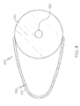
- FIG. 4 is a cross-sectional of the fuel injector assembly 220 through line 4-4 of FIG. 3 in accordance with an exemplary embodiment.
- the fuel injector assembly 220 has been removed from the dome shroud 223 and dome assembly 222.
- FIGS. 2-4 will be referenced below.
- the fuel injector assembly 220 includes an injector stem 310 mounted on the outer case 204 ( FIG. 2 ) with a flange 312.
- a first end 314 of the stem 310 is generally configured to be coupled to a fuel source (not shown) and a second end 316 of the stem 310 is generally coupled to a swirler apparatus 350, discussed below.
- the stem 310 extends approximately in a radial direction.
- the stem 310 may define or house a fuel delivery line 320 that directs the fuel received at the first end 314, through the stem 310, and to the swirler apparatus 350.
- the fuel may be liquid or gaseous.
- FIGS. 3 and 4 depict the fuel delivery line 320 as being defined by the walls of the stem 310, the fuel delivery line 320 may have any suitable configuration, including a discrete tube housed within the stem 310 or outside the stem 310 that delivers fuel to the swirler apparatus 350.
- An injector flow guide (or air guide) 330 is coupled to the injector stem 310.
- the flow guide 330 is attached to an outer surface of the the injector stem 310.
- the injector flow guide 330 is configured to receive a portion of the air flow (generally referenced as air flow 302) from the deswirl assembly 282 and to direct the air flow 302 into the swirler apparatus 350, as discussed in greater detail below.
- the injector flow guide 330 is defined by a wall 332 with edges attached to the stem 310 to form an air flow baffle or duct between the wall 332 and the outer surface of the injector stem 310.
- the wall 332 of the injector flow guide 330 defines an inlet 334 positioned generally along the length of the stem 310 to receive a portion of the air flow discharged from the deswirl assembly 282.
- the injector flow guide 330 may be fabricated from sheet metal.
- the injector flow guide 330 may be shaped and attached by any suitable technique to the injector stem 310, including welding or brazing.
- the injector flow guide 330 may have any suitable shape and configuration to provide the desired characteristics of air flow to be introduced into the swirler apparatus 350.
- the injector flow guide 330 may have any suitable length 336, including a length 336 that is a function of a length of the stem 310 between the flange 312 and the swirler apparatus 350.
- the inlet 334 is positioned at approximately the midpoint of the length of the stem 310. In other embodiments, the inlet 334 is arranged at a position between approximately 25% and approximately 75% of the length of the stem 310.
- the inlet 334 may have any suitable shape. In the depicted embodiment and as best shown in FIG.
- the inlet 334 has extended edges that taper to the outer wall of the stem 310.
- the cross-sectional shape of the injector flow guide 330 may be based on the desired volume, velocity, and pressure characteristics of the air flow. In the depicted embodiment, the cross-sectional shape is a semi-circular or half-moon shape, as best shown in the cross-sectional view of FIG. 4 .
- the injector flow guide 330 has a size and shape such that the fuel injector assembly 220 may be introduced or removed through an existing hole or orifice in the outer case 204, thereby enabling more efficient installation and maintenance.
- the fuel injector assembly 220 includes the swirler apparatus 350 that is coupled to the radial end 316 of the stem 310.
- the swirler apparatus 350 may include a manifold 360 that defines a generally axial flow path 362 with an inlet 364 and an outlet 366.
- the manifold 360 also defines at least one fuel outlet 368.
- the fuel outlet 368 is fluidly coupled to the fuel delivery line 320 and introduces fuel into the flow path 362.
- the fuel outlet 368 may include an atomizer to atomize the fuel.
- a plurality of fuel outlets 368 may be circumferentially arranged about the manifold 360. In general, the fuel outlet 368 may have any suitable configuration or arrangement for introducing fuel to the swirler apparatus 350.
- the manifold 360 additionally houses one or more airblast swirlers 370, 372.
- the swirlers 370, 372 are configured to shape the compressed air into a generally circular flow pattern to, among other things, assist in rapidly mixing the fuel and air to improve combustion of the fuel-air mixture upon exit from the fuel injector assembly 220.
- the swirlers 370, 372 function to atomize and partially mix the fuel with inlet air.
- a first or inner swirler 370 may be positioned within the flow path 362 defined by the manifold 360 to receive the air flow 302 from the injector flow guide 330, mix the air flow 302 with fuel introduced at the fuel outlet 368, and condition the mixture for combustion.
- a second or outer swirler 372 may be positioned downstream of the inner swirler 370 to introduce additional air flow 304 (e.g., a portion of the air within the plenum 228 ( FIG. 2 )) and condition the air flow 304 for mixing with the air and fuel mixture from the flow path 362.
- the resulting mixture exits the swirler apparatus 350 and the fuel injector assembly 220 and flows into the combustion chamber 214 to support ignition and combustion.
- the fuel outlet 368 is positioned between the swirlers 370, 372.
- the fuel outlet 368 may be positioned upstream of both swirlers 370, 372 or downstream of both swirlers 370, 372.
- additional swirlers may be provided or one of the swirlers 370, 372 may be omitted.
- swirlers 370, 372 may be any one of numerous types of swirlers, in the depicted embodiment, each is an axial swirler, although other arrangements may be provided, such as radial swirlers. Furthermore, the swirlers 370, 372 may include, as example, aerodynamic vanes, flat vanes or tangentially drilled holes. It will additionally be appreciated that the inner and outer swirlers 370, 372 may be configured to supply the same or different degree of swirl to the air and/or to supply the same or different amounts of air.
- air from the deswirl assembly 282 forces the air into an inward and axial flow into the combustor section 104.
- a portion of the air flow enters the injector flow guide 330 and is directed into the swirler apparatus 350.
- the air flow is mixed with fuel and additional air flow, conditioned, and directed into the combustion chamber 214.
- the fuel injector assembly 220 provides an improved mechanism for capturing the discharge air from the deswirl assembly 282 and creating a more balanced air distribution on both the inner and outer swirlers 370, 372.
- the injector flow guide 330 is attached to the fuel injector stem 310 to directly capture a portion of the air and direct it down toward an inlet of the inner swirler 370. In this manner, both the inner and outer swirlers 370, 372 receive a more comparable inlet flow distribution and improvements in fuel atomization may be realized.
- air discharged from the deswirl may be partially captured using the dome shroud and redistributed to the various flow features inside of the shroud, including the fuel injector swirlers.
- the inner swirler may not receive the benefit of the air pressure recovery and flow redistribution that the outer swirler does, thus creating the possibility of a reduced inlet pressure at the inner swirler, an imbalance in the air feeds to the injector, and a deterioration in the atomizer performance due to the reduced velocity of the inner swirler airstream.
- the fuel injector assembly 220 directs the air flow 302 through the flow guide 330 as needed or desired directly to the inner swirler 370 to improve air distribution on both the inner and outer swirlers 370, 372, and thus, improve operation.
- Exemplary embodiments discussed above may provide a gas turbine engine that operates more efficiently.
- the fuel injector assemblies provide a more direct aerodynamic coupling between the compressor and the combustor such that the air flow into the combustor is optimized.
- air flow may suffer decreased internal flow losses and improved static pressure recovery prior to introduction into the combustion chamber, thereby improving low pressure operation, including high-altitude ignition and light-around, as well as significant reductions in high-power combustion emissions, including substantial improvements in smoke levels.
- the engine is relatively inexpensive and simple to implement into existing engine configurations in which a centrifugal compressor is mounted with an axial combustor, particularly aircraft engines.
- exemplary embodiments discussed above are not limited to use in conjunction with a particular type of turbine engine.
- exemplary embodiments are, for convenience of explanation, depicted and described as being implemented in a multi-spool turbofan gas turbine jet engine, it will be appreciated that it can be implemented in various other types of turbines, and in various other systems and environments.
Landscapes
- Engineering & Computer Science (AREA)
- Chemical & Material Sciences (AREA)
- Combustion & Propulsion (AREA)
- Mechanical Engineering (AREA)
- General Engineering & Computer Science (AREA)
- Structures Of Non-Positive Displacement Pumps (AREA)
- Pre-Mixing And Non-Premixing Gas Burner (AREA)
Applications Claiming Priority (1)
| Application Number | Priority Date | Filing Date | Title |
|---|---|---|---|
| US13/901,219 US9404422B2 (en) | 2013-05-23 | 2013-05-23 | Gas turbine fuel injector having flow guide for receiving air flow |
Publications (3)
| Publication Number | Publication Date |
|---|---|
| EP2806217A2 true EP2806217A2 (de) | 2014-11-26 |
| EP2806217A3 EP2806217A3 (de) | 2015-04-01 |
| EP2806217B1 EP2806217B1 (de) | 2017-12-13 |
Family
ID=50628725
Family Applications (1)
| Application Number | Title | Priority Date | Filing Date |
|---|---|---|---|
| EP14167277.4A Not-in-force EP2806217B1 (de) | 2013-05-23 | 2014-05-06 | Gasturbinenmotoren mit Einspritzanordnungen |
Country Status (2)
| Country | Link |
|---|---|
| US (1) | US9404422B2 (de) |
| EP (1) | EP2806217B1 (de) |
Cited By (2)
| Publication number | Priority date | Publication date | Assignee | Title |
|---|---|---|---|---|
| EP3376111A1 (de) * | 2017-03-13 | 2018-09-19 | Rolls-Royce Corporation | Brennkammerhaube |
| US10982852B2 (en) | 2018-11-05 | 2021-04-20 | Rolls-Royce Corporation | Cowl integration to combustor wall |
Families Citing this family (9)
| Publication number | Priority date | Publication date | Assignee | Title |
|---|---|---|---|---|
| FR3035481B1 (fr) * | 2015-04-23 | 2017-05-05 | Snecma | Chambre de combustion de turbomachine comportant un dispositif de guidage de flux d'air de forme specifique |
| US10095218B2 (en) * | 2016-08-03 | 2018-10-09 | Siemens Aktiengesellschaft | Method and computer-readable model for additively manufacturing ducting arrangement with injector assemblies forming a shielding flow of air |
| KR102498300B1 (ko) | 2016-11-14 | 2023-02-09 | 한화에어로스페이스 주식회사 | 가스터빈용 연료 분사 장치 |
| US10907831B2 (en) * | 2018-05-07 | 2021-02-02 | Rolls-Royce Corporation | Ram pressure recovery fuel nozzle with a scoop |
| US11959401B1 (en) | 2023-03-24 | 2024-04-16 | Honeywell International Inc. | Deswirl system for gas turbine engine |
| GB202307700D0 (en) | 2023-05-23 | 2023-07-05 | Rolls Royce Plc | An improved combustor apparatus |
| GB202307701D0 (en) * | 2023-05-23 | 2023-07-05 | Rolls Royce Plc | An improved combustor apparatus |
| GB202408243D0 (en) * | 2024-06-10 | 2024-07-24 | Rolls Royce Plc | Available thrust |
| US12613035B1 (en) * | 2024-09-16 | 2026-04-28 | General Electric Company | Combustion section for a turbine engine |
Family Cites Families (25)
| Publication number | Priority date | Publication date | Assignee | Title |
|---|---|---|---|---|
| US2780061A (en) * | 1953-05-08 | 1957-02-05 | Lucas Industries Ltd | Liquid fuel burner for a combustion chamber provided with a surrounding air jacket |
| GB809514A (en) | 1956-04-03 | 1959-02-25 | Bristol Aero Engines Ltd | Improvements in or relating to combustion chambers |
| US3531937A (en) * | 1968-09-24 | 1970-10-06 | Curtiss Wright Corp | Fuel vaporizer for gas turbine engines |
| US3631675A (en) * | 1969-09-11 | 1972-01-04 | Gen Electric | Combustor primary air control |
| US4549402A (en) | 1982-05-26 | 1985-10-29 | Pratt & Whitney Aircraft Of Canada Limited | Combustor for a gas turbine engine |
| JPH0752014B2 (ja) | 1986-03-20 | 1995-06-05 | 株式会社日立製作所 | ガスタ−ビン燃焼器 |
| US4761959A (en) * | 1987-03-02 | 1988-08-09 | Allied-Signal Inc. | Adjustable non-piloted air blast fuel nozzle |
| US4928479A (en) * | 1987-12-28 | 1990-05-29 | Sundstrand Corporation | Annular combustor with tangential cooling air injection |
| JP3612331B2 (ja) * | 1993-06-01 | 2005-01-19 | プラット アンド ホイットニー カナダ,インコーポレイテッド | 半径方向に取り付けられる空気噴出型燃料噴射弁 |
| GB9326367D0 (en) | 1993-12-23 | 1994-02-23 | Rolls Royce Plc | Fuel injection apparatus |
| US6272865B1 (en) * | 1999-04-30 | 2001-08-14 | United Technologies Corporation | Swirler scoop and bearing plate for combustor |
| US6796129B2 (en) | 2001-08-29 | 2004-09-28 | Catalytica Energy Systems, Inc. | Design and control strategy for catalytic combustion system with a wide operating range |
| US6895756B2 (en) * | 2002-09-13 | 2005-05-24 | The Boeing Company | Compact swirl augmented afterburners for gas turbine engines |
| US7506511B2 (en) | 2003-12-23 | 2009-03-24 | Honeywell International Inc. | Reduced exhaust emissions gas turbine engine combustor |
| US7707835B2 (en) | 2005-06-15 | 2010-05-04 | General Electric Company | Axial flow sleeve for a turbine combustor and methods of introducing flow sleeve air |
| US7966822B2 (en) | 2005-06-30 | 2011-06-28 | General Electric Company | Reverse-flow gas turbine combustion system |
| US7624576B2 (en) * | 2005-07-18 | 2009-12-01 | Pratt & Whitney Canada Corporation | Low smoke and emissions fuel nozzle |
| US7500364B2 (en) * | 2005-11-22 | 2009-03-10 | Honeywell International Inc. | System for coupling flow from a centrifugal compressor to an axial combustor for gas turbines |
| US20070193272A1 (en) * | 2006-02-21 | 2007-08-23 | Woodward Fst, Inc. | Gas turbine engine fuel injector |
| US8196410B2 (en) * | 2007-05-18 | 2012-06-12 | Pratt & Whitney Canada Corp. | Stress reduction feature to improve fuel nozzle sheath durability |
| US20090173074A1 (en) | 2008-01-03 | 2009-07-09 | General Electric Company | Integrated fuel nozzle ifc |
| JP4838888B2 (ja) | 2009-05-27 | 2011-12-14 | 川崎重工業株式会社 | ガスタービン燃焼器 |
| US20110072823A1 (en) * | 2009-09-30 | 2011-03-31 | Daih-Yeou Chen | Gas turbine engine fuel injector |
| US8572978B2 (en) * | 2009-10-02 | 2013-11-05 | Hamilton Sundstrand Corporation | Fuel injector and aerodynamic flow device |
| FR2971039B1 (fr) * | 2011-02-02 | 2013-01-11 | Turbomeca | Injecteur de chambre de combustion de turbine a gaz a double circuit de carburant et chambre de combustion equipee d'au moins un tel injecteur |
-
2013
- 2013-05-23 US US13/901,219 patent/US9404422B2/en not_active Expired - Fee Related
-
2014
- 2014-05-06 EP EP14167277.4A patent/EP2806217B1/de not_active Not-in-force
Non-Patent Citations (1)
| Title |
|---|
| None |
Cited By (3)
| Publication number | Priority date | Publication date | Assignee | Title |
|---|---|---|---|---|
| EP3376111A1 (de) * | 2017-03-13 | 2018-09-19 | Rolls-Royce Corporation | Brennkammerhaube |
| US10619856B2 (en) | 2017-03-13 | 2020-04-14 | Rolls-Royce Corporation | Notched gas turbine combustor cowl |
| US10982852B2 (en) | 2018-11-05 | 2021-04-20 | Rolls-Royce Corporation | Cowl integration to combustor wall |
Also Published As
| Publication number | Publication date |
|---|---|
| US20140345286A1 (en) | 2014-11-27 |
| EP2806217A3 (de) | 2015-04-01 |
| EP2806217B1 (de) | 2017-12-13 |
| US9404422B2 (en) | 2016-08-02 |
Similar Documents
| Publication | Publication Date | Title |
|---|---|---|
| US9404422B2 (en) | Gas turbine fuel injector having flow guide for receiving air flow | |
| US12085281B2 (en) | Fuel nozzle and swirler | |
| US7966821B2 (en) | Reduced exhaust emissions gas turbine engine combustor | |
| US7500364B2 (en) | System for coupling flow from a centrifugal compressor to an axial combustor for gas turbines | |
| US11725819B2 (en) | Gas turbine fuel nozzle having a fuel passage within a swirler | |
| JP4997018B2 (ja) | 一次燃料噴射器及び複数の二次燃料噴射ポートを有するガスタービンエンジン燃焼器のミキサ組立体のためのパイロットミキサ | |
| EP2481985B1 (de) | Kraftstoffeinspritzanordnung | |
| US8555645B2 (en) | Fuel nozzle centerbody and method of assembling the same | |
| CN113357669B (zh) | 燃料喷射器流动装置 | |
| EP1847779A2 (de) | Optimierte Konfiguration eines Rückstromverbrennungssystems für eine Gasturbine | |
| EP4202303A1 (de) | Brennstoffdüse und verwirbler | |
| US12038176B2 (en) | Coupling a fuel nozzle purge flow directly to a swirler | |
| CN116136308B (zh) | 具有压降吹扫通道的旋流器套圈板 | |
| US20230213194A1 (en) | Turbine engine fuel premixer | |
| US12072099B2 (en) | Gas turbine fuel nozzle having a lip extending from the vanes of a swirler | |
| US11994295B2 (en) | Multi pressure drop swirler ferrule plate | |
| EP4675176A1 (de) | Turbinenmotor mit einem kraftstoffinjektor | |
| EP4678902A1 (de) | Verfahren zur zuführung eines brennstoffs zu einer brennkammer für einen turbinenmotor |
Legal Events
| Date | Code | Title | Description |
|---|---|---|---|
| PUAI | Public reference made under article 153(3) epc to a published international application that has entered the european phase |
Free format text: ORIGINAL CODE: 0009012 |
|
| 17P | Request for examination filed |
Effective date: 20140506 |
|
| AK | Designated contracting states |
Kind code of ref document: A2 Designated state(s): AL AT BE BG CH CY CZ DE DK EE ES FI FR GB GR HR HU IE IS IT LI LT LU LV MC MK MT NL NO PL PT RO RS SE SI SK SM TR |
|
| AX | Request for extension of the european patent |
Extension state: BA ME |
|
| PUAL | Search report despatched |
Free format text: ORIGINAL CODE: 0009013 |
|
| AK | Designated contracting states |
Kind code of ref document: A3 Designated state(s): AL AT BE BG CH CY CZ DE DK EE ES FI FR GB GR HR HU IE IS IT LI LT LU LV MC MK MT NL NO PL PT RO RS SE SI SK SM TR |
|
| AX | Request for extension of the european patent |
Extension state: BA ME |
|
| RIC1 | Information provided on ipc code assigned before grant |
Ipc: F23R 3/14 20060101AFI20150220BHEP Ipc: F23R 3/28 20060101ALI20150220BHEP |
|
| RAP1 | Party data changed (applicant data changed or rights of an application transferred) |
Owner name: HONEYWELL INTERNATIONAL INC. |
|
| 17Q | First examination report despatched |
Effective date: 20170118 |
|
| GRAP | Despatch of communication of intention to grant a patent |
Free format text: ORIGINAL CODE: EPIDOSNIGR1 |
|
| INTG | Intention to grant announced |
Effective date: 20170727 |
|
| GRAS | Grant fee paid |
Free format text: ORIGINAL CODE: EPIDOSNIGR3 |
|
| GRAA | (expected) grant |
Free format text: ORIGINAL CODE: 0009210 |
|
| REG | Reference to a national code |
Ref country code: GB Ref legal event code: FG4D |
|
| REG | Reference to a national code |
Ref country code: AT Ref legal event code: REF Ref document number: 954766 Country of ref document: AT Kind code of ref document: T Effective date: 20171215 Ref country code: CH Ref legal event code: EP |
|
| REG | Reference to a national code |
Ref country code: IE Ref legal event code: FG4D |
|
| REG | Reference to a national code |
Ref country code: DE Ref legal event code: R096 Ref document number: 602014018391 Country of ref document: DE |
|
| REG | Reference to a national code |
Ref country code: NL Ref legal event code: MP Effective date: 20171213 |
|
| PG25 | Lapsed in a contracting state [announced via postgrant information from national office to epo] |
Ref country code: NO Free format text: LAPSE BECAUSE OF FAILURE TO SUBMIT A TRANSLATION OF THE DESCRIPTION OR TO PAY THE FEE WITHIN THE PRESCRIBED TIME-LIMIT Effective date: 20180313 Ref country code: SE Free format text: LAPSE BECAUSE OF FAILURE TO SUBMIT A TRANSLATION OF THE DESCRIPTION OR TO PAY THE FEE WITHIN THE PRESCRIBED TIME-LIMIT Effective date: 20171213 Ref country code: FI Free format text: LAPSE BECAUSE OF FAILURE TO SUBMIT A TRANSLATION OF THE DESCRIPTION OR TO PAY THE FEE WITHIN THE PRESCRIBED TIME-LIMIT Effective date: 20171213 |
|
| REG | Reference to a national code |
Ref country code: AT Ref legal event code: MK05 Ref document number: 954766 Country of ref document: AT Kind code of ref document: T Effective date: 20171213 |
|
| PG25 | Lapsed in a contracting state [announced via postgrant information from national office to epo] |
Ref country code: RS Free format text: LAPSE BECAUSE OF FAILURE TO SUBMIT A TRANSLATION OF THE DESCRIPTION OR TO PAY THE FEE WITHIN THE PRESCRIBED TIME-LIMIT Effective date: 20171213 Ref country code: LV Free format text: LAPSE BECAUSE OF FAILURE TO SUBMIT A TRANSLATION OF THE DESCRIPTION OR TO PAY THE FEE WITHIN THE PRESCRIBED TIME-LIMIT Effective date: 20171213 Ref country code: HR Free format text: LAPSE BECAUSE OF FAILURE TO SUBMIT A TRANSLATION OF THE DESCRIPTION OR TO PAY THE FEE WITHIN THE PRESCRIBED TIME-LIMIT Effective date: 20171213 Ref country code: BG Free format text: LAPSE BECAUSE OF FAILURE TO SUBMIT A TRANSLATION OF THE DESCRIPTION OR TO PAY THE FEE WITHIN THE PRESCRIBED TIME-LIMIT Effective date: 20180313 Ref country code: GR Free format text: LAPSE BECAUSE OF FAILURE TO SUBMIT A TRANSLATION OF THE DESCRIPTION OR TO PAY THE FEE WITHIN THE PRESCRIBED TIME-LIMIT Effective date: 20180314 |
|
| PG25 | Lapsed in a contracting state [announced via postgrant information from national office to epo] |
Ref country code: NL Free format text: LAPSE BECAUSE OF FAILURE TO SUBMIT A TRANSLATION OF THE DESCRIPTION OR TO PAY THE FEE WITHIN THE PRESCRIBED TIME-LIMIT Effective date: 20171213 |
|
| PG25 | Lapsed in a contracting state [announced via postgrant information from national office to epo] |
Ref country code: SK Free format text: LAPSE BECAUSE OF FAILURE TO SUBMIT A TRANSLATION OF THE DESCRIPTION OR TO PAY THE FEE WITHIN THE PRESCRIBED TIME-LIMIT Effective date: 20171213 Ref country code: CY Free format text: LAPSE BECAUSE OF FAILURE TO SUBMIT A TRANSLATION OF THE DESCRIPTION OR TO PAY THE FEE WITHIN THE PRESCRIBED TIME-LIMIT Effective date: 20171213 Ref country code: EE Free format text: LAPSE BECAUSE OF FAILURE TO SUBMIT A TRANSLATION OF THE DESCRIPTION OR TO PAY THE FEE WITHIN THE PRESCRIBED TIME-LIMIT Effective date: 20171213 Ref country code: CZ Free format text: LAPSE BECAUSE OF FAILURE TO SUBMIT A TRANSLATION OF THE DESCRIPTION OR TO PAY THE FEE WITHIN THE PRESCRIBED TIME-LIMIT Effective date: 20171213 Ref country code: ES Free format text: LAPSE BECAUSE OF FAILURE TO SUBMIT A TRANSLATION OF THE DESCRIPTION OR TO PAY THE FEE WITHIN THE PRESCRIBED TIME-LIMIT Effective date: 20171213 |
|
| PG25 | Lapsed in a contracting state [announced via postgrant information from national office to epo] |
Ref country code: IS Free format text: LAPSE BECAUSE OF FAILURE TO SUBMIT A TRANSLATION OF THE DESCRIPTION OR TO PAY THE FEE WITHIN THE PRESCRIBED TIME-LIMIT Effective date: 20180413 Ref country code: SM Free format text: LAPSE BECAUSE OF FAILURE TO SUBMIT A TRANSLATION OF THE DESCRIPTION OR TO PAY THE FEE WITHIN THE PRESCRIBED TIME-LIMIT Effective date: 20171213 Ref country code: AT Free format text: LAPSE BECAUSE OF FAILURE TO SUBMIT A TRANSLATION OF THE DESCRIPTION OR TO PAY THE FEE WITHIN THE PRESCRIBED TIME-LIMIT Effective date: 20171213 Ref country code: IT Free format text: LAPSE BECAUSE OF FAILURE TO SUBMIT A TRANSLATION OF THE DESCRIPTION OR TO PAY THE FEE WITHIN THE PRESCRIBED TIME-LIMIT Effective date: 20171213 Ref country code: RO Free format text: LAPSE BECAUSE OF FAILURE TO SUBMIT A TRANSLATION OF THE DESCRIPTION OR TO PAY THE FEE WITHIN THE PRESCRIBED TIME-LIMIT Effective date: 20171213 Ref country code: PL Free format text: LAPSE BECAUSE OF FAILURE TO SUBMIT A TRANSLATION OF THE DESCRIPTION OR TO PAY THE FEE WITHIN THE PRESCRIBED TIME-LIMIT Effective date: 20171213 |
|
| REG | Reference to a national code |
Ref country code: DE Ref legal event code: R097 Ref document number: 602014018391 Country of ref document: DE |
|
| PLBE | No opposition filed within time limit |
Free format text: ORIGINAL CODE: 0009261 |
|
| STAA | Information on the status of an ep patent application or granted ep patent |
Free format text: STATUS: NO OPPOSITION FILED WITHIN TIME LIMIT |
|
| 26N | No opposition filed |
Effective date: 20180914 |
|
| PG25 | Lapsed in a contracting state [announced via postgrant information from national office to epo] |
Ref country code: DK Free format text: LAPSE BECAUSE OF FAILURE TO SUBMIT A TRANSLATION OF THE DESCRIPTION OR TO PAY THE FEE WITHIN THE PRESCRIBED TIME-LIMIT Effective date: 20171213 |
|
| REG | Reference to a national code |
Ref country code: CH Ref legal event code: PL |
|
| GBPC | Gb: european patent ceased through non-payment of renewal fee |
Effective date: 20180506 |
|
| REG | Reference to a national code |
Ref country code: BE Ref legal event code: MM Effective date: 20180531 |
|
| PG25 | Lapsed in a contracting state [announced via postgrant information from national office to epo] |
Ref country code: MC Free format text: LAPSE BECAUSE OF FAILURE TO SUBMIT A TRANSLATION OF THE DESCRIPTION OR TO PAY THE FEE WITHIN THE PRESCRIBED TIME-LIMIT Effective date: 20171213 |
|
| REG | Reference to a national code |
Ref country code: IE Ref legal event code: MM4A |
|
| PG25 | Lapsed in a contracting state [announced via postgrant information from national office to epo] |
Ref country code: CH Free format text: LAPSE BECAUSE OF NON-PAYMENT OF DUE FEES Effective date: 20180531 Ref country code: SI Free format text: LAPSE BECAUSE OF FAILURE TO SUBMIT A TRANSLATION OF THE DESCRIPTION OR TO PAY THE FEE WITHIN THE PRESCRIBED TIME-LIMIT Effective date: 20171213 Ref country code: LI Free format text: LAPSE BECAUSE OF NON-PAYMENT OF DUE FEES Effective date: 20180531 |
|
| PG25 | Lapsed in a contracting state [announced via postgrant information from national office to epo] |
Ref country code: LU Free format text: LAPSE BECAUSE OF NON-PAYMENT OF DUE FEES Effective date: 20180506 |
|
| PG25 | Lapsed in a contracting state [announced via postgrant information from national office to epo] |
Ref country code: FR Free format text: LAPSE BECAUSE OF NON-PAYMENT OF DUE FEES Effective date: 20180531 Ref country code: IE Free format text: LAPSE BECAUSE OF NON-PAYMENT OF DUE FEES Effective date: 20180506 Ref country code: GB Free format text: LAPSE BECAUSE OF NON-PAYMENT OF DUE FEES Effective date: 20180506 |
|
| PG25 | Lapsed in a contracting state [announced via postgrant information from national office to epo] |
Ref country code: BE Free format text: LAPSE BECAUSE OF NON-PAYMENT OF DUE FEES Effective date: 20180531 |
|
| PGFP | Annual fee paid to national office [announced via postgrant information from national office to epo] |
Ref country code: DE Payment date: 20190531 Year of fee payment: 6 |
|
| PG25 | Lapsed in a contracting state [announced via postgrant information from national office to epo] |
Ref country code: MT Free format text: LAPSE BECAUSE OF NON-PAYMENT OF DUE FEES Effective date: 20180506 |
|
| PG25 | Lapsed in a contracting state [announced via postgrant information from national office to epo] |
Ref country code: TR Free format text: LAPSE BECAUSE OF FAILURE TO SUBMIT A TRANSLATION OF THE DESCRIPTION OR TO PAY THE FEE WITHIN THE PRESCRIBED TIME-LIMIT Effective date: 20171213 |
|
| PG25 | Lapsed in a contracting state [announced via postgrant information from national office to epo] |
Ref country code: HU Free format text: LAPSE BECAUSE OF FAILURE TO SUBMIT A TRANSLATION OF THE DESCRIPTION OR TO PAY THE FEE WITHIN THE PRESCRIBED TIME-LIMIT; INVALID AB INITIO Effective date: 20140506 Ref country code: PT Free format text: LAPSE BECAUSE OF FAILURE TO SUBMIT A TRANSLATION OF THE DESCRIPTION OR TO PAY THE FEE WITHIN THE PRESCRIBED TIME-LIMIT Effective date: 20171213 |
|
| PG25 | Lapsed in a contracting state [announced via postgrant information from national office to epo] |
Ref country code: MK Free format text: LAPSE BECAUSE OF NON-PAYMENT OF DUE FEES Effective date: 20171213 Ref country code: LT Free format text: LAPSE BECAUSE OF FAILURE TO SUBMIT A TRANSLATION OF THE DESCRIPTION OR TO PAY THE FEE WITHIN THE PRESCRIBED TIME-LIMIT Effective date: 20171213 |
|
| PG25 | Lapsed in a contracting state [announced via postgrant information from national office to epo] |
Ref country code: AL Free format text: LAPSE BECAUSE OF FAILURE TO SUBMIT A TRANSLATION OF THE DESCRIPTION OR TO PAY THE FEE WITHIN THE PRESCRIBED TIME-LIMIT Effective date: 20171213 |
|
| REG | Reference to a national code |
Ref country code: DE Ref legal event code: R119 Ref document number: 602014018391 Country of ref document: DE |
|
| PG25 | Lapsed in a contracting state [announced via postgrant information from national office to epo] |
Ref country code: DE Free format text: LAPSE BECAUSE OF NON-PAYMENT OF DUE FEES Effective date: 20201201 |
|
| P01 | Opt-out of the competence of the unified patent court (upc) registered |
Effective date: 20230525 |