EP2806183B1 - Flexible support shaft - Google Patents
Flexible support shaft Download PDFInfo
- Publication number
- EP2806183B1 EP2806183B1 EP12865631.1A EP12865631A EP2806183B1 EP 2806183 B1 EP2806183 B1 EP 2806183B1 EP 12865631 A EP12865631 A EP 12865631A EP 2806183 B1 EP2806183 B1 EP 2806183B1
- Authority
- EP
- European Patent Office
- Prior art keywords
- compression spring
- support shaft
- section
- flexible support
- elastic member
- Prior art date
- Legal status (The legal status is an assumption and is not a legal conclusion. Google has not performed a legal analysis and makes no representation as to the accuracy of the status listed.)
- Active
Links
- 230000006835 compression Effects 0.000 claims description 43
- 238000007906 compression Methods 0.000 claims description 43
- 238000009826 distribution Methods 0.000 claims description 4
- 238000005266 casting Methods 0.000 claims description 2
- 238000001125 extrusion Methods 0.000 claims description 2
- 238000001746 injection moulding Methods 0.000 claims description 2
- 238000000465 moulding Methods 0.000 claims description 2
- XLYOFNOQVPJJNP-UHFFFAOYSA-N water Substances O XLYOFNOQVPJJNP-UHFFFAOYSA-N 0.000 claims description 2
- 238000004804 winding Methods 0.000 claims description 2
- 230000035939 shock Effects 0.000 description 4
- 239000006096 absorbing agent Substances 0.000 description 2
- 239000002131 composite material Substances 0.000 description 2
- 238000010521 absorption reaction Methods 0.000 description 1
- 238000009776 industrial production Methods 0.000 description 1
- 239000000203 mixture Substances 0.000 description 1
- 238000012986 modification Methods 0.000 description 1
- 230000004048 modification Effects 0.000 description 1
- 230000002787 reinforcement Effects 0.000 description 1
- 239000000243 solution Substances 0.000 description 1
- 239000000126 substance Substances 0.000 description 1
Images


Classifications
-
- F—MECHANICAL ENGINEERING; LIGHTING; HEATING; WEAPONS; BLASTING
- F16—ENGINEERING ELEMENTS AND UNITS; GENERAL MEASURES FOR PRODUCING AND MAINTAINING EFFECTIVE FUNCTIONING OF MACHINES OR INSTALLATIONS; THERMAL INSULATION IN GENERAL
- F16F—SPRINGS; SHOCK-ABSORBERS; MEANS FOR DAMPING VIBRATION
- F16F3/00—Spring units consisting of several springs, e.g. for obtaining a desired spring characteristic
- F16F3/08—Spring units consisting of several springs, e.g. for obtaining a desired spring characteristic with springs made of a material having high internal friction, e.g. rubber
- F16F3/10—Spring units consisting of several springs, e.g. for obtaining a desired spring characteristic with springs made of a material having high internal friction, e.g. rubber combined with springs made of steel or other material having low internal friction
- F16F3/12—Spring units consisting of several springs, e.g. for obtaining a desired spring characteristic with springs made of a material having high internal friction, e.g. rubber combined with springs made of steel or other material having low internal friction the steel spring being in contact with the rubber spring
Definitions
- the present invention relates to support shafts, in particular, to a flexible support shaft.
- the patent application EP 08184848 A2 discloses a composite spring comprising a tubular elastomeric body 10 and reinforcement means in the form of a coil spring 12 embedded in and bonded to the body for controlling deformation of the body such that the spring's force/deflection curve has two stiff regions, each characterized by essentially stable compression of the body, and an intermediate soft 30 region characterized by unstable but symmetric bulging of the body.
- the composite spring is not suitable for supporting because the elastomeric body will form a helical path.
- the present invention aims at providing a flexible support shaft, to solve the problem that the support shaft in the prior art only plays a supporting role and insufficient attention is paid to shock absorption.
- the embodiment of the present invention is implemented by a flexible support shaft configured to be arranged on a first object to flexibly support a second object moving relative to the first object, wherein the flexible support shaft comprises a first connecting flange for being mounted on the first object, a compression spring having one end arranged on the first connecting flange, an elastic member configured to be embedded by the compression spring to change the elasticity of the compression spring, and a second connecting flange arranged on the other end of the compression spring to support the second object.
- the flexible support shaft acts not only as a support but also as a shock absorber for the second object in relative motion. Furthermore, since the compression spring is embedded in the elastic member, the elastic member changes the elasticity and rigidity of the compression spring.
- a flexible support shaft 10 provided by the present invention is configured to be arranged on a first object (not shown) to flexibly support a second object (not shown) moving relative to the first object.
- the flexible support shaft 10 comprises a first connecting flange 20 for being mounted on the first object, a compression spring 30 having one end mounted on the first connecting flange 20, an elastic member 40 configured to be embedded by the compression spring 30 to change the elasticity of the compression spring 30, and a second connecting flange 50 mounted on the other end of the compression spring 30 to support the second object.
- the elastic member 40 and the compression spring 30 are formed integrally.
- the compression spring 30 is a cylinder formed by winding a spring wire, and a cross section of the spring wire is a circle.
- the compression spring 30 defines a plurality of mounting holes 31 arranged along an axis of the compression spring 30 on the spring wire at two opposite ends of the compression spring 30.
- the distribution of the distances between every two adjacent spring wire circles of the compression spring 30 is a close-sparse-close arrangement from the center of the compression spring 30 to two opposite ends of the compression spring 30.
- the distribution of the distances between every two adjacent spring wire circles of the compression spring 30 can be adjusted, so that the elasticity and rigidity of the flexible support shaft 10 are adjusted.
- the first connecting flange 20 is circular disc ring shaped.
- the first connecting flange 20 is provided with a plurality of first fixing holes 21.
- the second connecting flange 50 is circular disc ring shaped.
- the second connecting flange 50 is provided with a plurality of second fixing holes (not shown).
- the first fixing holes 21 and the second fixing holes are corresponding to the mounting holes 31.
- Locking members 60 such as screws, pass through the first fixing holes 21 and are screwed and locked with corresponding mounting holes 31, such that the first connecting flange 20 is fixed onto the compression spring 30.
- the locking members 60 pass through the second fixing hole and are screwed and locked with corresponding mounting holes 31, such that the second connecting flange 50 is fixed onto the compression spring 30.
- a cross section of the elastic member 40 is a torus.
- the elastic member 40 comprises a middle section 41 arranged in the middle of the compression spring 30 and a first section 42 and a second section 43 respectively arranged on two opposite ends of the middle section 41.
- the thicknesses of the first section 42 and the second section 43 are less than the thickness of the middle section 41.
- An outer surface of the middle section 41 protrudes beyond outer surfaces of the first section 42 and the second section 43 to form a water retaining ring 45.
- the elasticity of the flexible support shaft 10 may be adjusted according to the requirement by adjusting the volume of the middle section 41 of the elastic member 40.
- the outer surface and/or an inner surface of the middle section 41 of the elastic member 40 is dug with a recess 46 which doesn't penetrate the middle section 41, such that the volume of the middle section 41 of the elastic member 40 is changed, and the elasticity of the middle section 41 is thereby changed.
- the form of the recess 46 may be varied, for example, in a blind hole manner.
- the elastic member 40 and the compression spring 30 are formed through injection molding, extrusion molding, or casting molding.
- the flexible support shaft 10 acts not only as a support but also as a shock absorber for the second object in relative motion. Furthermore, since the compression spring 30 is embedded in the elastic member 40, the elastic member 40 changes the elasticity and rigidity of the compression spring 30.
- the bearing capacity and deformation of the flexible support shaft 10 are set by changing each parameter of the compression spring 30, and the elasticity and rigidity of the flexible support shaft 10 can be adjusted by changing the chemical composition, geometry size, and distribution status of the elastic member 40.
Description
- The present invention relates to support shafts, in particular, to a flexible support shaft.
- In industrial production, it may often meet the situation that a motion object moves relative to a fixed object, and the motion object is supported by the fixed object through a support shaft. An existing support shaft only plays a supporting role, and there is insufficient attention to the shock to the support shaft from the motion object and to the fixed object from the motion object through the support shaft, which may cause the damage of the support shaft and the fixed object. Therefore, the present invention needs to improve the support shaft.
- The patent application
EP 08184848 A2 elastomeric body 10 and reinforcement means in the form of a coil spring 12 embedded in and bonded to the body for controlling deformation of the body such that the spring's force/deflection curve has two stiff regions, each characterized by essentially stable compression of the body, and an intermediate soft 30 region characterized by unstable but symmetric bulging of the body. However, the composite spring is not suitable for supporting because the elastomeric body will form a helical path. - The present invention aims at providing a flexible support shaft, to solve the problem that the support shaft in the prior art only plays a supporting role and insufficient attention is paid to shock absorption.
- The embodiment of the present invention is implemented by a flexible support shaft configured to be arranged on a first object to flexibly support a second object moving relative to the first object, wherein the flexible support shaft comprises a first connecting flange for being mounted on the first object, a compression spring having one end arranged on the first connecting flange, an elastic member configured to be embedded by the compression spring to change the elasticity of the compression spring, and a second connecting flange arranged on the other end of the compression spring to support the second object.
- Because of the design of the compression spring and the elastic member thereon, the flexible support shaft acts not only as a support but also as a shock absorber for the second object in relative motion. Furthermore, since the compression spring is embedded in the elastic member, the elastic member changes the elasticity and rigidity of the compression spring.
-
-
Figure 1 is a three-dimensional exploded view of a flexible support shaft according to an embodiment of the present invention. -
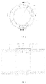
Figure 2 is an end face view of the flexible support shaft infigure 1 . -
Figure 3 is a cross-section view of the flexible support shaft infigure 2 , along the A-A line. -
Figure 4 is a cross-section view of the flexible support shaft infigure 2 , along the B-B line. -
Figure 5 is a cross-section view of the flexible support shaft infigure 2 , along the D-D line. - To make the objectives, technical solutions and advantages of the present invention be clearer, the present invention will be further described hereinafter with reference to the accompany drawings and embodiments. It shall be understood that, the embodiments described herein are only intended to illustrate but not to limit the present invention.
- Referring to
figure 1 to figure 5 , aflexible support shaft 10 provided by the present invention is configured to be arranged on a first object (not shown) to flexibly support a second object (not shown) moving relative to the first object. Theflexible support shaft 10 comprises a first connectingflange 20 for being mounted on the first object, acompression spring 30 having one end mounted on the first connectingflange 20, anelastic member 40 configured to be embedded by thecompression spring 30 to change the elasticity of thecompression spring 30, and a second connectingflange 50 mounted on the other end of thecompression spring 30 to support the second object. Theelastic member 40 and thecompression spring 30 are formed integrally. - The
compression spring 30 is a cylinder formed by winding a spring wire, and a cross section of the spring wire is a circle. Thecompression spring 30 defines a plurality ofmounting holes 31 arranged along an axis of thecompression spring 30 on the spring wire at two opposite ends of thecompression spring 30. The distribution of the distances between every two adjacent spring wire circles of thecompression spring 30 is a close-sparse-close arrangement from the center of thecompression spring 30 to two opposite ends of thecompression spring 30. The distribution of the distances between every two adjacent spring wire circles of thecompression spring 30 can be adjusted, so that the elasticity and rigidity of theflexible support shaft 10 are adjusted. - The first connecting
flange 20 is circular disc ring shaped. The first connectingflange 20 is provided with a plurality of first fixing holes 21. The second connectingflange 50 is circular disc ring shaped. The second connectingflange 50 is provided with a plurality of second fixing holes (not shown). The first fixing holes 21 and the second fixing holes are corresponding to themounting holes 31. Lockingmembers 60, such as screws, pass through the first fixing holes 21 and are screwed and locked withcorresponding mounting holes 31, such that the first connectingflange 20 is fixed onto thecompression spring 30. Thelocking members 60 pass through the second fixing hole and are screwed and locked withcorresponding mounting holes 31, such that the second connectingflange 50 is fixed onto thecompression spring 30. - A cross section of the
elastic member 40 is a torus. Theelastic member 40 comprises amiddle section 41 arranged in the middle of thecompression spring 30 and afirst section 42 and asecond section 43 respectively arranged on two opposite ends of themiddle section 41. The thicknesses of thefirst section 42 and thesecond section 43 are less than the thickness of themiddle section 41. An outer surface of themiddle section 41 protrudes beyond outer surfaces of thefirst section 42 and thesecond section 43 to form a water retainingring 45. - In practical use, the elasticity of the
flexible support shaft 10 may be adjusted according to the requirement by adjusting the volume of themiddle section 41 of theelastic member 40. For example, in this embodiment, the outer surface and/or an inner surface of themiddle section 41 of theelastic member 40 is dug with arecess 46 which doesn't penetrate themiddle section 41, such that the volume of themiddle section 41 of theelastic member 40 is changed, and the elasticity of themiddle section 41 is thereby changed. The form of therecess 46 may be varied, for example, in a blind hole manner. - The
elastic member 40 and thecompression spring 30 are formed through injection molding, extrusion molding, or casting molding. - Because of the design of the
compression spring 30 and theelastic member 40 thereon, theflexible support shaft 10 acts not only as a support but also as a shock absorber for the second object in relative motion. Furthermore, since thecompression spring 30 is embedded in theelastic member 40, theelastic member 40 changes the elasticity and rigidity of thecompression spring 30. - In the present invention, the bearing capacity and deformation of the
flexible support shaft 10 are set by changing each parameter of thecompression spring 30, and the elasticity and rigidity of theflexible support shaft 10 can be adjusted by changing the chemical composition, geometry size, and distribution status of theelastic member 40. - What described above are only preferred embodiments of the present disclosure but are not intended to limit the scope of the present disclosure, any modifications, equivalent replacements and improvements etc. made within the spirit and principle of the present invention, should be included in the protection scope of the present invention.
Claims (7)
- A flexible support shaft (10), configured to be arranged on a first object to flexibly support a second object moving relative to the first object, wherein the flexible support shaft (10) comprises a first connecting flange (20) for being mounted on the first object, a compression spring (30) having one end arranged on the first connecting flange (20), an elastic member (40) configured to be embedded by the compression spring (30) to change the elasticity of the compression spring (30), and a second connecting flange (50) arranged on the other end of the compression spring (30) to support the second object, a cross section of the elastic member is a torus, characterized in that the elastic member comprises a middle section (41) arranged in the middle of the compression spring and a first section (42) and a second section (43) respectively arranged on two opposite ends of the middle section, and the thicknesses of the first section and the second section are less than the thickness of the middle section, the outer surface and/or an inner surface of the middle section of the elastic member is dug with a recess (46) which doesn't penetrate the middle section.
- The flexible support shaft (10) of claim 1, characterized in that the compression spring (30) is a cylinder formed by winding a spring wire, and a cross section of the spring wire is a circle.
- The flexible support shaft (10) of claim 2, characterized in that the distribution of the distances between every two adjacent spring wire circles of the compression spring (30) is a close-sparse-close arrangement from the center of the compression spring (30) to two opposite ends of the compression spring (30).
- The flexible support shaft (10) of claim 2, characterized in that the compression spring (30) defines a plurality of mounting holes (31) arranged along an axis of the compression spring on the spring wire at two opposite ends of the compression spring (30), the first connecting flange (20) is provided with a plurality of first fixing holes, the second connecting flange (50) is provided with a plurality of second fixing holes, and the first fixing holes and the second fixing holes are corresponding to the mounting holes.
- The flexible support shaft (10) of claim 4, characterized in that an outer surface of the middle section (41) protrudes beyond outer surfaces of the first section (42) and the second section (43) to form a water retaining ring (45).
- The flexible support shaft (10) of claim 1, characterized in that the elastic member (40) and the compression spring (30) are formed integrally.
- The flexible support shaft (10) of claim 6, characterized in that the elastic member (40) and the compression spring (30) are formed through injection molding, extrusion molding, or casting molding.
Applications Claiming Priority (1)
| Application Number | Priority Date | Filing Date | Title |
|---|---|---|---|
| PCT/CN2012/070647 WO2013107034A1 (en) | 2012-01-20 | 2012-01-20 | Flexible support shaft |
Publications (3)
| Publication Number | Publication Date |
|---|---|
| EP2806183A1 EP2806183A1 (en) | 2014-11-26 |
| EP2806183A4 EP2806183A4 (en) | 2015-10-21 |
| EP2806183B1 true EP2806183B1 (en) | 2016-11-09 |
Family
ID=48798519
Family Applications (1)
| Application Number | Title | Priority Date | Filing Date |
|---|---|---|---|
| EP12865631.1A Active EP2806183B1 (en) | 2012-01-20 | 2012-01-20 | Flexible support shaft |
Country Status (7)
| Country | Link |
|---|---|
| US (1) | US9377073B2 (en) |
| EP (1) | EP2806183B1 (en) |
| JP (1) | JP5977367B2 (en) |
| KR (1) | KR101834610B1 (en) |
| ES (1) | ES2614027T3 (en) |
| PL (1) | PL2806183T3 (en) |
| WO (1) | WO2013107034A1 (en) |
Families Citing this family (4)
| Publication number | Priority date | Publication date | Assignee | Title |
|---|---|---|---|---|
| US20150233680A1 (en) * | 2012-11-30 | 2015-08-20 | Renton Coil Spring Company | Resiliently mounted armor panel |
| CN104084815A (en) * | 2014-07-02 | 2014-10-08 | 无锡烨隆精密机械有限公司 | Large-stroke rapid flexible supporting structure |
| JP7225896B2 (en) | 2018-02-28 | 2023-02-21 | 株式会社デンソー | battery monitoring system |
| JP7225897B2 (en) | 2018-02-28 | 2023-02-21 | 株式会社デンソー | battery monitoring system |
Family Cites Families (18)
| Publication number | Priority date | Publication date | Assignee | Title |
|---|---|---|---|---|
| US2605099A (en) * | 1949-01-07 | 1952-07-29 | Firestone Tire & Rubber Co | Rubber-metal spring |
| US3879024A (en) * | 1973-11-01 | 1975-04-22 | Apex Molded Prod Co | Mounting device |
| USRE33696E (en) * | 1984-12-12 | 1991-09-24 | The Paton Corporation | Composite spring |
| JPS61144439A (en) * | 1984-12-12 | 1986-07-02 | ザ パットン コーポレイション | Composite spring |
| US4731966A (en) * | 1985-06-19 | 1988-03-22 | Takafumi Fujita | Vibration energy absorber device |
| FR2603959B1 (en) * | 1986-09-12 | 1992-07-24 | Intertechnique Sa | SHOCK AND VIBRATION DAMPING DEVICE |
| US4874154A (en) * | 1987-06-19 | 1989-10-17 | Acushnet Company | Encapsulated spring assembly for reclining furniture |
| JPH06507227A (en) * | 1991-04-29 | 1994-08-11 | パトン,エイチ.ネイル | Composite elastomer springs and mounting devices |
| KR200152096Y1 (en) * | 1994-11-10 | 1999-07-15 | 윤종용 | Compressor mounting structure |
| AU2004201650B2 (en) * | 2003-02-19 | 2011-03-24 | Dreamwell, Ltd. | Multi-stranded coil spring |
| JP4421500B2 (en) * | 2005-03-23 | 2010-02-24 | 倉敷化工株式会社 | Vibration isolator |
| JP2007309361A (en) | 2006-05-16 | 2007-11-29 | Fuji Electric Holdings Co Ltd | Vibration damping device |
| JP2007315425A (en) * | 2006-05-23 | 2007-12-06 | Ntn Corp | Compression coil spring |
| CN200981588Y (en) * | 2006-12-04 | 2007-11-28 | 王福民 | Flexible shock absorber |
| JP2010091058A (en) * | 2008-10-10 | 2010-04-22 | Union Bed Seizo Kk | Coil spring and mattress using the same |
| DE102009022810A1 (en) | 2009-05-27 | 2010-12-02 | Bayerische Motoren Werke Aktiengesellschaft | Spring strut for wheel of motorcycle, has damping piston provided with piston rod, and two springs formed as spiral springs, where one of spiral springs is wound linearly, and other spiral spring wound progressively |
| CN201483254U (en) * | 2009-07-15 | 2010-05-26 | 孙建勇 | Elastic supporting piece |
| CN101913051A (en) | 2010-07-09 | 2010-12-15 | 临沂开元轴承有限公司 | Internal support special for superfinishing bearing ring |
-
2012
- 2012-01-20 KR KR1020147022134A patent/KR101834610B1/en active IP Right Grant
- 2012-01-20 EP EP12865631.1A patent/EP2806183B1/en active Active
- 2012-01-20 PL PL12865631T patent/PL2806183T3/en unknown
- 2012-01-20 US US14/372,966 patent/US9377073B2/en active Active
- 2012-01-20 ES ES12865631.1T patent/ES2614027T3/en active Active
- 2012-01-20 WO PCT/CN2012/070647 patent/WO2013107034A1/en active Application Filing
- 2012-01-20 JP JP2014552464A patent/JP5977367B2/en active Active
Non-Patent Citations (1)
| Title |
|---|
| None * |
Also Published As
| Publication number | Publication date |
|---|---|
| PL2806183T3 (en) | 2017-06-30 |
| KR101834610B1 (en) | 2018-03-05 |
| US9377073B2 (en) | 2016-06-28 |
| EP2806183A4 (en) | 2015-10-21 |
| KR20140114014A (en) | 2014-09-25 |
| JP2015504145A (en) | 2015-02-05 |
| WO2013107034A1 (en) | 2013-07-25 |
| ES2614027T3 (en) | 2017-05-29 |
| JP5977367B2 (en) | 2016-08-24 |
| EP2806183A1 (en) | 2014-11-26 |
| US20150076754A1 (en) | 2015-03-19 |
Similar Documents
| Publication | Publication Date | Title |
|---|---|---|
| EP2806183B1 (en) | Flexible support shaft | |
| US9121494B2 (en) | Gear arrangement | |
| JP6027392B2 (en) | Non pneumatic tire | |
| JP5733469B2 (en) | Single axis actuator | |
| CN101909911B (en) | Vehicle stabilizer | |
| US20100284733A1 (en) | Axial Ball Joint with Impact Damping Mechanism | |
| EP3118479B1 (en) | Aircraft landing gear shock absorber | |
| JP6478790B2 (en) | Shaft spring | |
| US20150266351A1 (en) | Mount for Wheel Suspensions of a Motor Vehicle | |
| EP1906045B1 (en) | Cartridge and rod end isolator | |
| EP3141769B1 (en) | Thrust sliding bearing | |
| JP5648727B1 (en) | Ball screw | |
| US10202142B2 (en) | Rack guide device and steering apparatus including same | |
| CN103249957B (en) | Tripod rolling element with spring ring | |
| CN202149171U (en) | Shock buffering device and installation structure thereof | |
| CN105276141B (en) | Linear actuator | |
| JP2018109434A (en) | Air spring | |
| WO2019146624A1 (en) | Strut mount | |
| CN106499721B (en) | Motor shaft | |
| CN106836060B (en) | Warning guardrail for injection molding machine control room | |
| JP2021089026A (en) | Cylindrical lamination rubber and adjustment method of spring characteristics of the same | |
| KR101172456B1 (en) | Lateral Flexure of Mirror Assembly for Telescope | |
| JP2022018165A (en) | Vibration damping buch | |
| JP2018203030A (en) | Steering device for vehicle | |
| WO2017046927A1 (en) | Wave motion generator for wave motion gear device |
Legal Events
| Date | Code | Title | Description |
|---|---|---|---|
| PUAI | Public reference made under article 153(3) epc to a published international application that has entered the european phase |
Free format text: ORIGINAL CODE: 0009012 |
|
| 17P | Request for examination filed |
Effective date: 20140731 |
|
| AK | Designated contracting states |
Kind code of ref document: A1 Designated state(s): AL AT BE BG CH CY CZ DE DK EE ES FI FR GB GR HR HU IE IS IT LI LT LU LV MC MK MT NL NO PL PT RO RS SE SI SK SM TR |
|
| DAX | Request for extension of the european patent (deleted) | ||
| RA4 | Supplementary search report drawn up and despatched (corrected) |
Effective date: 20150922 |
|
| RIC1 | Information provided on ipc code assigned before grant |
Ipc: F16F 7/116 20060101ALI20150916BHEP Ipc: F16F 7/00 20060101AFI20150916BHEP Ipc: F16F 3/12 20060101ALI20150916BHEP |
|
| GRAP | Despatch of communication of intention to grant a patent |
Free format text: ORIGINAL CODE: EPIDOSNIGR1 |
|
| INTG | Intention to grant announced |
Effective date: 20160720 |
|
| GRAS | Grant fee paid |
Free format text: ORIGINAL CODE: EPIDOSNIGR3 |
|
| GRAA | (expected) grant |
Free format text: ORIGINAL CODE: 0009210 |
|
| AK | Designated contracting states |
Kind code of ref document: B1 Designated state(s): AL AT BE BG CH CY CZ DE DK EE ES FI FR GB GR HR HU IE IS IT LI LT LU LV MC MK MT NL NO PL PT RO RS SE SI SK SM TR |
|
| REG | Reference to a national code |
Ref country code: GB Ref legal event code: FG4D |
|
| REG | Reference to a national code |
Ref country code: AT Ref legal event code: REF Ref document number: 844240 Country of ref document: AT Kind code of ref document: T Effective date: 20161115 Ref country code: CH Ref legal event code: EP |
|
| REG | Reference to a national code |
Ref country code: IE Ref legal event code: FG4D |
|
| REG | Reference to a national code |
Ref country code: DE Ref legal event code: R096 Ref document number: 602012025303 Country of ref document: DE |
|
| REG | Reference to a national code |
Ref country code: NL Ref legal event code: FP |
|
| REG | Reference to a national code |
Ref country code: FR Ref legal event code: PLFP Year of fee payment: 6 |
|
| PG25 | Lapsed in a contracting state [announced via postgrant information from national office to epo] |
Ref country code: LV Free format text: LAPSE BECAUSE OF FAILURE TO SUBMIT A TRANSLATION OF THE DESCRIPTION OR TO PAY THE FEE WITHIN THE PRESCRIBED TIME-LIMIT Effective date: 20161109 |
|
| REG | Reference to a national code |
Ref country code: LT Ref legal event code: MG4D |
|
| PG25 | Lapsed in a contracting state [announced via postgrant information from national office to epo] |
Ref country code: LT Free format text: LAPSE BECAUSE OF FAILURE TO SUBMIT A TRANSLATION OF THE DESCRIPTION OR TO PAY THE FEE WITHIN THE PRESCRIBED TIME-LIMIT Effective date: 20161109 Ref country code: SE Free format text: LAPSE BECAUSE OF FAILURE TO SUBMIT A TRANSLATION OF THE DESCRIPTION OR TO PAY THE FEE WITHIN THE PRESCRIBED TIME-LIMIT Effective date: 20161109 Ref country code: NO Free format text: LAPSE BECAUSE OF FAILURE TO SUBMIT A TRANSLATION OF THE DESCRIPTION OR TO PAY THE FEE WITHIN THE PRESCRIBED TIME-LIMIT Effective date: 20170209 Ref country code: GR Free format text: LAPSE BECAUSE OF FAILURE TO SUBMIT A TRANSLATION OF THE DESCRIPTION OR TO PAY THE FEE WITHIN THE PRESCRIBED TIME-LIMIT Effective date: 20170210 |
|
| REG | Reference to a national code |
Ref country code: ES Ref legal event code: FG2A Ref document number: 2614027 Country of ref document: ES Kind code of ref document: T3 Effective date: 20170529 |
|
| PG25 | Lapsed in a contracting state [announced via postgrant information from national office to epo] |
Ref country code: FI Free format text: LAPSE BECAUSE OF FAILURE TO SUBMIT A TRANSLATION OF THE DESCRIPTION OR TO PAY THE FEE WITHIN THE PRESCRIBED TIME-LIMIT Effective date: 20161109 Ref country code: PT Free format text: LAPSE BECAUSE OF FAILURE TO SUBMIT A TRANSLATION OF THE DESCRIPTION OR TO PAY THE FEE WITHIN THE PRESCRIBED TIME-LIMIT Effective date: 20170309 Ref country code: IS Free format text: LAPSE BECAUSE OF FAILURE TO SUBMIT A TRANSLATION OF THE DESCRIPTION OR TO PAY THE FEE WITHIN THE PRESCRIBED TIME-LIMIT Effective date: 20170309 Ref country code: HR Free format text: LAPSE BECAUSE OF FAILURE TO SUBMIT A TRANSLATION OF THE DESCRIPTION OR TO PAY THE FEE WITHIN THE PRESCRIBED TIME-LIMIT Effective date: 20161109 Ref country code: RS Free format text: LAPSE BECAUSE OF FAILURE TO SUBMIT A TRANSLATION OF THE DESCRIPTION OR TO PAY THE FEE WITHIN THE PRESCRIBED TIME-LIMIT Effective date: 20161109 |
|
| PG25 | Lapsed in a contracting state [announced via postgrant information from national office to epo] |
Ref country code: DK Free format text: LAPSE BECAUSE OF FAILURE TO SUBMIT A TRANSLATION OF THE DESCRIPTION OR TO PAY THE FEE WITHIN THE PRESCRIBED TIME-LIMIT Effective date: 20161109 Ref country code: CZ Free format text: LAPSE BECAUSE OF FAILURE TO SUBMIT A TRANSLATION OF THE DESCRIPTION OR TO PAY THE FEE WITHIN THE PRESCRIBED TIME-LIMIT Effective date: 20161109 Ref country code: EE Free format text: LAPSE BECAUSE OF FAILURE TO SUBMIT A TRANSLATION OF THE DESCRIPTION OR TO PAY THE FEE WITHIN THE PRESCRIBED TIME-LIMIT Effective date: 20161109 Ref country code: SK Free format text: LAPSE BECAUSE OF FAILURE TO SUBMIT A TRANSLATION OF THE DESCRIPTION OR TO PAY THE FEE WITHIN THE PRESCRIBED TIME-LIMIT Effective date: 20161109 Ref country code: RO Free format text: LAPSE BECAUSE OF FAILURE TO SUBMIT A TRANSLATION OF THE DESCRIPTION OR TO PAY THE FEE WITHIN THE PRESCRIBED TIME-LIMIT Effective date: 20161109 |
|
| REG | Reference to a national code |
Ref country code: DE Ref legal event code: R097 Ref document number: 602012025303 Country of ref document: DE |
|
| PG25 | Lapsed in a contracting state [announced via postgrant information from national office to epo] |
Ref country code: BG Free format text: LAPSE BECAUSE OF FAILURE TO SUBMIT A TRANSLATION OF THE DESCRIPTION OR TO PAY THE FEE WITHIN THE PRESCRIBED TIME-LIMIT Effective date: 20170209 Ref country code: IT Free format text: LAPSE BECAUSE OF FAILURE TO SUBMIT A TRANSLATION OF THE DESCRIPTION OR TO PAY THE FEE WITHIN THE PRESCRIBED TIME-LIMIT Effective date: 20161109 Ref country code: SM Free format text: LAPSE BECAUSE OF FAILURE TO SUBMIT A TRANSLATION OF THE DESCRIPTION OR TO PAY THE FEE WITHIN THE PRESCRIBED TIME-LIMIT Effective date: 20161109 |
|
| PLBE | No opposition filed within time limit |
Free format text: ORIGINAL CODE: 0009261 |
|
| STAA | Information on the status of an ep patent application or granted ep patent |
Free format text: STATUS: NO OPPOSITION FILED WITHIN TIME LIMIT |
|
| PG25 | Lapsed in a contracting state [announced via postgrant information from national office to epo] |
Ref country code: MC Free format text: LAPSE BECAUSE OF FAILURE TO SUBMIT A TRANSLATION OF THE DESCRIPTION OR TO PAY THE FEE WITHIN THE PRESCRIBED TIME-LIMIT Effective date: 20161109 |
|
| 26N | No opposition filed |
Effective date: 20170810 |
|
| REG | Reference to a national code |
Ref country code: IE Ref legal event code: MM4A |
|
| PG25 | Lapsed in a contracting state [announced via postgrant information from national office to epo] |
Ref country code: SI Free format text: LAPSE BECAUSE OF FAILURE TO SUBMIT A TRANSLATION OF THE DESCRIPTION OR TO PAY THE FEE WITHIN THE PRESCRIBED TIME-LIMIT Effective date: 20161109 Ref country code: LU Free format text: LAPSE BECAUSE OF NON-PAYMENT OF DUE FEES Effective date: 20170120 |
|
| REG | Reference to a national code |
Ref country code: FR Ref legal event code: PLFP Year of fee payment: 7 |
|
| PG25 | Lapsed in a contracting state [announced via postgrant information from national office to epo] |
Ref country code: IE Free format text: LAPSE BECAUSE OF NON-PAYMENT OF DUE FEES Effective date: 20170120 |
|
| PG25 | Lapsed in a contracting state [announced via postgrant information from national office to epo] |
Ref country code: MT Free format text: LAPSE BECAUSE OF NON-PAYMENT OF DUE FEES Effective date: 20170120 |
|
| PG25 | Lapsed in a contracting state [announced via postgrant information from national office to epo] |
Ref country code: HU Free format text: LAPSE BECAUSE OF FAILURE TO SUBMIT A TRANSLATION OF THE DESCRIPTION OR TO PAY THE FEE WITHIN THE PRESCRIBED TIME-LIMIT; INVALID AB INITIO Effective date: 20120120 |
|
| PG25 | Lapsed in a contracting state [announced via postgrant information from national office to epo] |
Ref country code: CY Free format text: LAPSE BECAUSE OF FAILURE TO SUBMIT A TRANSLATION OF THE DESCRIPTION OR TO PAY THE FEE WITHIN THE PRESCRIBED TIME-LIMIT Effective date: 20161109 |
|
| PG25 | Lapsed in a contracting state [announced via postgrant information from national office to epo] |
Ref country code: MK Free format text: LAPSE BECAUSE OF FAILURE TO SUBMIT A TRANSLATION OF THE DESCRIPTION OR TO PAY THE FEE WITHIN THE PRESCRIBED TIME-LIMIT Effective date: 20161109 |
|
| REG | Reference to a national code |
Ref country code: AT Ref legal event code: UEP Ref document number: 844240 Country of ref document: AT Kind code of ref document: T Effective date: 20161109 |
|
| PG25 | Lapsed in a contracting state [announced via postgrant information from national office to epo] |
Ref country code: AL Free format text: LAPSE BECAUSE OF FAILURE TO SUBMIT A TRANSLATION OF THE DESCRIPTION OR TO PAY THE FEE WITHIN THE PRESCRIBED TIME-LIMIT Effective date: 20161109 |
|
| PGFP | Annual fee paid to national office [announced via postgrant information from national office to epo] |
Ref country code: CH Payment date: 20220119 Year of fee payment: 11 Ref country code: AT Payment date: 20220120 Year of fee payment: 11 |
|
| PGFP | Annual fee paid to national office [announced via postgrant information from national office to epo] |
Ref country code: TR Payment date: 20220113 Year of fee payment: 11 Ref country code: PL Payment date: 20220105 Year of fee payment: 11 Ref country code: NL Payment date: 20220119 Year of fee payment: 11 Ref country code: ES Payment date: 20220325 Year of fee payment: 11 Ref country code: BE Payment date: 20220119 Year of fee payment: 11 |
|
| PGFP | Annual fee paid to national office [announced via postgrant information from national office to epo] |
Ref country code: FR Payment date: 20230124 Year of fee payment: 12 |
|
| PGFP | Annual fee paid to national office [announced via postgrant information from national office to epo] |
Ref country code: GB Payment date: 20230119 Year of fee payment: 12 Ref country code: DE Payment date: 20230123 Year of fee payment: 12 |
|
| REG | Reference to a national code |
Ref country code: CH Ref legal event code: PL |
|
| REG | Reference to a national code |
Ref country code: NL Ref legal event code: MM Effective date: 20230201 |
|
| REG | Reference to a national code |
Ref country code: AT Ref legal event code: MM01 Ref document number: 844240 Country of ref document: AT Kind code of ref document: T Effective date: 20230120 |
|
| REG | Reference to a national code |
Ref country code: BE Ref legal event code: MM Effective date: 20230131 |
|
| PG25 | Lapsed in a contracting state [announced via postgrant information from national office to epo] |
Ref country code: NL Free format text: LAPSE BECAUSE OF NON-PAYMENT OF DUE FEES Effective date: 20230201 Ref country code: LI Free format text: LAPSE BECAUSE OF NON-PAYMENT OF DUE FEES Effective date: 20230131 Ref country code: CH Free format text: LAPSE BECAUSE OF NON-PAYMENT OF DUE FEES Effective date: 20230131 Ref country code: AT Free format text: LAPSE BECAUSE OF NON-PAYMENT OF DUE FEES Effective date: 20230120 |
|
| PG25 | Lapsed in a contracting state [announced via postgrant information from national office to epo] |
Ref country code: BE Free format text: LAPSE BECAUSE OF NON-PAYMENT OF DUE FEES Effective date: 20230131 |
|
| REG | Reference to a national code |
Ref country code: ES Ref legal event code: FD2A Effective date: 20240402 |
|
| PG25 | Lapsed in a contracting state [announced via postgrant information from national office to epo] |
Ref country code: ES Free format text: LAPSE BECAUSE OF NON-PAYMENT OF DUE FEES Effective date: 20230121 |