EP2806175B1 - Hot upset solid shaft sub-assembly - Google Patents
Hot upset solid shaft sub-assembly Download PDFInfo
- Publication number
- EP2806175B1 EP2806175B1 EP14169306.9A EP14169306A EP2806175B1 EP 2806175 B1 EP2806175 B1 EP 2806175B1 EP 14169306 A EP14169306 A EP 14169306A EP 2806175 B1 EP2806175 B1 EP 2806175B1
- Authority
- EP
- European Patent Office
- Prior art keywords
- solid shaft
- shaft
- yoke
- assembly
- solid
- Prior art date
- Legal status (The legal status is an assumption and is not a legal conclusion. Google has not performed a legal analysis and makes no representation as to the accuracy of the status listed.)
- Not-in-force
Links
- 239000007787 solid Substances 0.000 title claims description 79
- 238000000034 method Methods 0.000 claims description 5
- 230000000295 complement effect Effects 0.000 claims description 4
- 230000008878 coupling Effects 0.000 claims description 3
- 238000010168 coupling process Methods 0.000 claims description 3
- 238000005859 coupling reaction Methods 0.000 claims description 3
- 238000003825 pressing Methods 0.000 claims description 2
- 238000010438 heat treatment Methods 0.000 claims 2
- 238000000429 assembly Methods 0.000 description 10
- 230000014759 maintenance of location Effects 0.000 description 9
- 230000000712 assembly Effects 0.000 description 3
- 238000003780 insertion Methods 0.000 description 3
- 230000037431 insertion Effects 0.000 description 3
- 238000004519 manufacturing process Methods 0.000 description 3
- 241000219793 Trifolium Species 0.000 description 2
- 230000004075 alteration Effects 0.000 description 1
- 230000004323 axial length Effects 0.000 description 1
- 238000003754 machining Methods 0.000 description 1
- 230000013011 mating Effects 0.000 description 1
- 239000002184 metal Substances 0.000 description 1
- 238000006467 substitution reaction Methods 0.000 description 1
- 238000003466 welding Methods 0.000 description 1
Images


Classifications
-
- F—MECHANICAL ENGINEERING; LIGHTING; HEATING; WEAPONS; BLASTING
- F16—ENGINEERING ELEMENTS AND UNITS; GENERAL MEASURES FOR PRODUCING AND MAINTAINING EFFECTIVE FUNCTIONING OF MACHINES OR INSTALLATIONS; THERMAL INSULATION IN GENERAL
- F16D—COUPLINGS FOR TRANSMITTING ROTATION; CLUTCHES; BRAKES
- F16D3/00—Yielding couplings, i.e. with means permitting movement between the connected parts during the drive
- F16D3/16—Universal joints in which flexibility is produced by means of pivots or sliding or rolling connecting parts
- F16D3/26—Hooke's joints or other joints with an equivalent intermediate member to which each coupling part is pivotally or slidably connected
- F16D3/38—Hooke's joints or other joints with an equivalent intermediate member to which each coupling part is pivotally or slidably connected with a single intermediate member with trunnions or bearings arranged on two axes perpendicular to one another
- F16D3/382—Hooke's joints or other joints with an equivalent intermediate member to which each coupling part is pivotally or slidably connected with a single intermediate member with trunnions or bearings arranged on two axes perpendicular to one another constructional details of other than the intermediate member
- F16D3/387—Fork construction; Mounting of fork on shaft; Adapting shaft for mounting of fork
-
- B—PERFORMING OPERATIONS; TRANSPORTING
- B62—LAND VEHICLES FOR TRAVELLING OTHERWISE THAN ON RAILS
- B62D—MOTOR VEHICLES; TRAILERS
- B62D1/00—Steering controls, i.e. means for initiating a change of direction of the vehicle
- B62D1/02—Steering controls, i.e. means for initiating a change of direction of the vehicle vehicle-mounted
- B62D1/16—Steering columns
-
- F—MECHANICAL ENGINEERING; LIGHTING; HEATING; WEAPONS; BLASTING
- F16—ENGINEERING ELEMENTS AND UNITS; GENERAL MEASURES FOR PRODUCING AND MAINTAINING EFFECTIVE FUNCTIONING OF MACHINES OR INSTALLATIONS; THERMAL INSULATION IN GENERAL
- F16C—SHAFTS; FLEXIBLE SHAFTS; ELEMENTS OR CRANKSHAFT MECHANISMS; ROTARY BODIES OTHER THAN GEARING ELEMENTS; BEARINGS
- F16C3/00—Shafts; Axles; Cranks; Eccentrics
- F16C3/02—Shafts; Axles
-
- F—MECHANICAL ENGINEERING; LIGHTING; HEATING; WEAPONS; BLASTING
- F16—ENGINEERING ELEMENTS AND UNITS; GENERAL MEASURES FOR PRODUCING AND MAINTAINING EFFECTIVE FUNCTIONING OF MACHINES OR INSTALLATIONS; THERMAL INSULATION IN GENERAL
- F16C—SHAFTS; FLEXIBLE SHAFTS; ELEMENTS OR CRANKSHAFT MECHANISMS; ROTARY BODIES OTHER THAN GEARING ELEMENTS; BEARINGS
- F16C3/00—Shafts; Axles; Cranks; Eccentrics
- F16C3/02—Shafts; Axles
- F16C3/023—Shafts; Axles made of several parts, e.g. by welding
-
- F—MECHANICAL ENGINEERING; LIGHTING; HEATING; WEAPONS; BLASTING
- F16—ENGINEERING ELEMENTS AND UNITS; GENERAL MEASURES FOR PRODUCING AND MAINTAINING EFFECTIVE FUNCTIONING OF MACHINES OR INSTALLATIONS; THERMAL INSULATION IN GENERAL
- F16D—COUPLINGS FOR TRANSMITTING ROTATION; CLUTCHES; BRAKES
- F16D1/00—Couplings for rigidly connecting two coaxial shafts or other movable machine elements
- F16D1/06—Couplings for rigidly connecting two coaxial shafts or other movable machine elements for attachment of a member on a shaft or on a shaft-end
- F16D1/064—Couplings for rigidly connecting two coaxial shafts or other movable machine elements for attachment of a member on a shaft or on a shaft-end non-disconnectable
- F16D1/072—Couplings for rigidly connecting two coaxial shafts or other movable machine elements for attachment of a member on a shaft or on a shaft-end non-disconnectable involving plastic deformation
-
- F—MECHANICAL ENGINEERING; LIGHTING; HEATING; WEAPONS; BLASTING
- F16—ENGINEERING ELEMENTS AND UNITS; GENERAL MEASURES FOR PRODUCING AND MAINTAINING EFFECTIVE FUNCTIONING OF MACHINES OR INSTALLATIONS; THERMAL INSULATION IN GENERAL
- F16C—SHAFTS; FLEXIBLE SHAFTS; ELEMENTS OR CRANKSHAFT MECHANISMS; ROTARY BODIES OTHER THAN GEARING ELEMENTS; BEARINGS
- F16C2226/00—Joining parts; Fastening; Assembling or mounting parts
- F16C2226/50—Positive connections
- F16C2226/52—Positive connections with plastic deformation, e.g. caulking or staking
-
- F—MECHANICAL ENGINEERING; LIGHTING; HEATING; WEAPONS; BLASTING
- F16—ENGINEERING ELEMENTS AND UNITS; GENERAL MEASURES FOR PRODUCING AND MAINTAINING EFFECTIVE FUNCTIONING OF MACHINES OR INSTALLATIONS; THERMAL INSULATION IN GENERAL
- F16C—SHAFTS; FLEXIBLE SHAFTS; ELEMENTS OR CRANKSHAFT MECHANISMS; ROTARY BODIES OTHER THAN GEARING ELEMENTS; BEARINGS
- F16C2326/00—Articles relating to transporting
- F16C2326/20—Land vehicles
- F16C2326/24—Steering systems, e.g. steering rods or columns
-
- F—MECHANICAL ENGINEERING; LIGHTING; HEATING; WEAPONS; BLASTING
- F16—ENGINEERING ELEMENTS AND UNITS; GENERAL MEASURES FOR PRODUCING AND MAINTAINING EFFECTIVE FUNCTIONING OF MACHINES OR INSTALLATIONS; THERMAL INSULATION IN GENERAL
- F16D—COUPLINGS FOR TRANSMITTING ROTATION; CLUTCHES; BRAKES
- F16D1/00—Couplings for rigidly connecting two coaxial shafts or other movable machine elements
- F16D1/10—Quick-acting couplings in which the parts are connected by simply bringing them together axially
- F16D2001/102—Quick-acting couplings in which the parts are connected by simply bringing them together axially the torque is transmitted via polygon shaped connections
-
- Y—GENERAL TAGGING OF NEW TECHNOLOGICAL DEVELOPMENTS; GENERAL TAGGING OF CROSS-SECTIONAL TECHNOLOGIES SPANNING OVER SEVERAL SECTIONS OF THE IPC; TECHNICAL SUBJECTS COVERED BY FORMER USPC CROSS-REFERENCE ART COLLECTIONS [XRACs] AND DIGESTS
- Y10—TECHNICAL SUBJECTS COVERED BY FORMER USPC
- Y10T—TECHNICAL SUBJECTS COVERED BY FORMER US CLASSIFICATION
- Y10T29/00—Metal working
- Y10T29/49—Method of mechanical manufacture
- Y10T29/49826—Assembling or joining
- Y10T29/49833—Punching, piercing or reaming part by surface of second part
- Y10T29/49835—Punching, piercing or reaming part by surface of second part with shaping
-
- Y—GENERAL TAGGING OF NEW TECHNOLOGICAL DEVELOPMENTS; GENERAL TAGGING OF CROSS-SECTIONAL TECHNOLOGIES SPANNING OVER SEVERAL SECTIONS OF THE IPC; TECHNICAL SUBJECTS COVERED BY FORMER USPC CROSS-REFERENCE ART COLLECTIONS [XRACs] AND DIGESTS
- Y10—TECHNICAL SUBJECTS COVERED BY FORMER USPC
- Y10T—TECHNICAL SUBJECTS COVERED BY FORMER US CLASSIFICATION
- Y10T29/00—Metal working
- Y10T29/49—Method of mechanical manufacture
- Y10T29/49826—Assembling or joining
- Y10T29/49908—Joining by deforming
- Y10T29/49938—Radially expanding part in cavity, aperture, or hollow body
Definitions
- the present disclosure generally relates to shaft assemblies and, more specifically, to solid shaft sub-assemblies for a vehicle intermediate shaft.
- Intermediate shafts are typically comprised of two main components: a tubular sub-assembly and a solid shaft sub-assembly. This combination allows for telescoping of the intermediate shaft so that it may be installed in a car, and potentially collapse during a crash scenario. Examples of such intermediate shaft assemblies can be found in DE 10 2010 002 494 A1 and US 2011/0219907 A1 .
- the solid shaft sub-assembly is traditionally made by an interference fit between a solid shaft and a yoke.
- the interference is typically created by forming a serration on the yoke, and forming a complementing but slightly different serration on the solid shaft. These slightly differing serrations create an overlap of the serration flanks on the yoke to the serration flanks on the shaft. This connection holds together the yoke and shaft so that they may form the solid shaft sub-assembly.
- Some solid shaft sub-assemblies may undergo a "staking" operation to add an axial retention feature after the yoke and shaft are pressed together. This feature or “stake” is a small patch of metal on the solid shaft that is deformed past the original outer diameter.
- JP 2007-040240 A describes this manufacturing method and provides examples of the resulting solid shaft sub-assemblies.
- the serrations may be difficult to design, difficult to manufacture, and may be easily damaged. Additionally, the interference connection may be limited in the axial retention force it can withstand before failing. Because of this limited retention force, a redundant axial retention feature is required.
- Traditional solid shaft sub-assemblies may also encounter difficulties during assembly. For example, the required load to press the two components together may be too high or too low, the components may not press together on a parallel path, the serrations of the components may not connect as desired, or the components may not press together for the desired distance. Accordingly, it is desirable to provide an improved solid shaft sub-assembly.
- a solid shaft sub-assembly is provided by claim 1.
- an intermediate shaft for a steering column assembly is provided by claim 2.
- FIG. 1 illustrates an exemplary intermediate shaft assembly 10 that generally includes a tubular shaft sub-assembly 12 and a solid shaft sub-assembly 14.
- Tubular shaft 12 generally includes an open end 16 and a yoke end 18.
- intermediate shaft assembly 10 is configured for use in a vehicle steering column assembly (not shown).
- the shaft assemblies 10, 14 described herein may be used in any other suitable system.
- solid shaft sub-assembly 14 includes a solid shaft 20 and a yoke 22.
- Solid shaft 20 includes a first end 28 and a second end 30.
- First end 28 is configured for insertion into yoke 22 to facilitate coupling therebetween
- second end 30 is configured for insertion into tubular shaft open end 16 to facilitate coupling between solid shaft 20 and tubular shaft 12.
- Second end 30 may be coupled to tubular shaft 12 by any suitable means such as, for example, press-fitting or welding.
- solid shaft 20 is generally cylindrical and includes a first portion 32 having a first cross-section or diameter D1, a second portion 34 having a second cross-section or diameter D2.
- First diameter D1 is larger than second diameter D2 such that first portion 32 includes a shoulder 36, and second portion 34 includes an end face 38.
- solid shaft 20 may have alternative shapes such as, for example, a two-groove configuration ( FIGS. 5-7 ) and a clover configuration ( FIGS. 8-10 ).
- Yoke 22 generally includes bearing holes 42, an inner surface 44, a bottom surface 46, and an inner wall 48 that defines an aperture 50.
- aperture 50 has a non-circular cross-section.
- aperture 50 is generally hexagonal.
- aperture 50 may have any suitable non-circular geometry that enables solid shaft sub-assembly 14 to function as described herein, such as four-projection geometry ( FIGS. 8-10 ).
- the inner wall 48 includes projections extending inwardly into the aperture ( FIGS. 5-7 ).
- FIGS. 5-7 illustrate a solid shaft sub-assembly 114 according to the invention that is similar to the solid shaft sub-assembly 14 shown in FIGS. 1-4 , and like reference numerals indicate like parts.
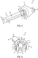
- Sub-assembly 114 is similar to sub-assembly 14 except solid shaft 20 includes grooves 116 extending axially along the length of shaft 20, and yoke inner wall 48 includes projections 118 extending inwardly into aperture 50. Grooves 116 are configured to each receive a projection 118 when solid shaft second portion 34 is inserted into aperture 50.
- FIGS. 8-10 illustrate a solid shaft sub-assembly 214 that is similar to the solid shaft sub-assemblies 14, 114, and like reference numerals indicate like parts.
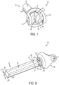
- Sub-assembly 214 is similar to sub-assemblies 14, 114 except solid shaft 20 includes projections 216 along the axial length of shaft 20, and yoke inner wall includes grooves 218 configured to receive projections 216 when solid shaft second portion 34 is inserted into aperture 50.
- solid shaft 20 and yoke 22 are provided to a desired assembly location (not shown).
- shaft 20 may be fixtured (i.e., secured) in an assembly machine (not shown) in a vertical position, and yoke 22 positioned in a desired orientation relative to solid shaft 20 and fixtured in the assembly machine to maintain the relative orientation to shaft 20.
- yoke 22 may be positioned by hand in the desired orientation (see FIGS. 3 , 6 , 9 ) and then fixtured. Once solid shaft 20 and yoke 22 are fixtured, the assembly operation may begin.
- the assembly operation includes the hot upsetting of solid shaft second portion 34 to deform second portion 34 against yoke inner surface 44 (see. FIGS. 4 , 7 , 10 ) and/or fill the designed mating yoke geometry of aperture 50.
- shaft second portion 34 is inserted into yoke aperture 50 until yoke bottom surface 46 abuts against solid shaft shoulder 36 and prevents further insertion of solid shaft 20 into yoke aperture 50.
- Shaft second portion 34 is then heated and deformed to form an enlarged second portion end face 54 ( FIGS. 4 , 7 , 10 ) and/or to fill any gaps present between second portion outer surface 40 and yoke inner wall 48.
- shaft second portion 34 is formed with a cross-sectional profile 52 substantially complementary to the cross-sectional profile of aperture 50.
- the assembly machine or other device may press against shaft end face 38 of the heated shaft second portion 34 such that the shaft second portion 34 is deformed back against yoke inner surface 44 and is forced radially outward against yoke inner wall 48.
- the assembly operation forms cross-sectional profile 52 that is substantially complementary to the cross-sectional profile of aperture 50 such that shaft second portion outer surface 40 and yoke inner wall 48 are interlocked to facilitate increased torsional strength.
- This operation also facilitates preventing the need for machining operation, preventing the need for serrations on the shaft and yoke interfaces, preventing the need for staking operations, and providing increased axial retention between shaft 20 and yoke 22.
- a first electrode (not shown) is attached to shaft second portion 34 and a second electrode (not shown) is attached to yoke 22.
- Shaft second portion 34 is inserted into yoke aperture 50 (see FIGS. 3 , 6 , 9 ) and an electrical current is directed from the first electrode to the second electrode through both solid shaft 20 and yoke 22.
- a resistance is created between portions of shaft second portion 34 and yoke 22 that are in contact, which subsequently heats shaft second portion 34 to a temperature at which it can be deformed (e.g., when second portion 34 glows red or orange).
- a cylinder (not shown) is then pressed against second portion end face 38 and at least a portion of shaft 20 is pressed and deformed against yoke inner face 44 and inner wall 48.
- shaft second portion 34 subsequently includes an enlarged end face 54 having a diameter D3 ( FIGS. 4 , 7 , 10 ).
- End face diameter D3 is larger than the cross-sectional geometry of yoke aperture 50 such that end face 54, along with solid shaft shoulder 36, facilitates preventing removal of shaft 20 from yoke 22 in the axial direction.
- a portion of the solid shaft is heated and inserted through an aperture of the yoke.
- the heated portion is then deformed such that it overlaps the yoke geometry and/or fills gaps between the solid shaft and a yoke inner wall that defines the aperture.
- the deformed portion of the solid shaft is consequently larger than the yoke aperture to improve axial retention of the shaft in the yoke, and/or the deformed portion conforms to the non-circular geometry of the yoke inner wall to improve torsional strength between the solid shaft and the yoke.
- the non-circular geometry may be, for example, hexagonal, grooved, or have a clover shape.
- the I-shaft assembly provides improved orientation variance between the yoke and solid shaft, an increased axial retention force resistance to failure, a yoke-to-shaft connection that does not require separate manufacturing operations for torsional and axial retention features, a yoke-to-shaft connection that does not need a redundant axial retention feature, and multiple measureable locations to validate the integrity of the yoke-to-shaft connection.
Landscapes
- Engineering & Computer Science (AREA)
- General Engineering & Computer Science (AREA)
- Mechanical Engineering (AREA)
- Ocean & Marine Engineering (AREA)
- Chemical & Material Sciences (AREA)
- Combustion & Propulsion (AREA)
- Transportation (AREA)
- Shafts, Cranks, Connecting Bars, And Related Bearings (AREA)
Description
- The present disclosure generally relates to shaft assemblies and, more specifically, to solid shaft sub-assemblies for a vehicle intermediate shaft.
- Intermediate shafts are typically comprised of two main components: a tubular sub-assembly and a solid shaft sub-assembly. This combination allows for telescoping of the intermediate shaft so that it may be installed in a car, and potentially collapse during a crash scenario. Examples of such intermediate shaft assemblies can be found in
DE 10 2010 002 494 A1 andUS 2011/0219907 A1 . - The solid shaft sub-assembly is traditionally made by an interference fit between a solid shaft and a yoke. The interference is typically created by forming a serration on the yoke, and forming a complementing but slightly different serration on the solid shaft. These slightly differing serrations create an overlap of the serration flanks on the yoke to the serration flanks on the shaft. This connection holds together the yoke and shaft so that they may form the solid shaft sub-assembly.
- Some solid shaft sub-assemblies may undergo a "staking" operation to add an axial retention feature after the yoke and shaft are pressed together. This feature or "stake" is a small patch of metal on the solid shaft that is deformed past the original outer diameter.
JP 2007-040240 A -
US 4,110,051 describes a solid shaft sub-assembly in accordance with the preamble of claim 1. - However, with some known solid shaft sub-assemblies, the serrations may be difficult to design, difficult to manufacture, and may be easily damaged. Additionally, the interference connection may be limited in the axial retention force it can withstand before failing. Because of this limited retention force, a redundant axial retention feature is required. Traditional solid shaft sub-assemblies may also encounter difficulties during assembly. For example, the required load to press the two components together may be too high or too low, the components may not press together on a parallel path, the serrations of the components may not connect as desired, or the components may not press together for the desired distance. Accordingly, it is desirable to provide an improved solid shaft sub-assembly.
- In one aspect, a solid shaft sub-assembly is provided by claim 1.
- In another aspect, an intermediate shaft for a steering column assembly is provided by claim 2.
- In yet another aspect, a method of assembling a solid shaft sub-assembly is provided by claim 3.
- These and other advantages and features will become more apparent from the following description taken in conjunction with the drawings.
- The subject matter which is regarded as the invention is particularly pointed out and distinctly claimed in the claims at the conclusion of the specification. The foregoing and other features, and advantages of the invention are apparent from the following detailed description taken in conjunction with the accompanying drawings in which:
-
FIG. 1 is a perspective view of an exemplary intermediate shaft assembly having a solid shaft sub-assembly, and before assembly, that is not in accordance with the claims; -
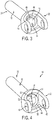
FIG. 2 is perspective view of the solid shaft sub-assembly shown inFIG. 1 before assembly; -
FIG. 3 is a perspective view of the solid shaft sub-assembly shown inFIG. 1 and during assembly; -
FIG. 4 is a perspective view of the solid shaft sub-assembly shown inFIGS. 2 and3 and after assembly; -
FIG. 5 is a perspective view of an embodiment of a solid shaft sub-assembly before assembly; -
FIG. 6 is a perspective view of the solid shaft sub-assembly shown inFIG. 5 and during assembly; -
FIG. 7 is a perspective view of the solid shaft sub-assembly shown inFIGS. 5 and 6 , and after assembly; -
FIG. 8 is a perspective view of a shaft sub-assembly that is not in accordance with the claims before assembly; -
FIG. 9 is a perspective view of the solid shaft sub-assembly shown inFIG. 8 and during assembly; and -
FIG. 10 is a perspective view of the solid shaft sub-assembly shown inFIGS. 8 and9 , and after assembly. - Referring now to the Figures, where the invention will be described with reference to specific embodiments, without limiting same,
FIG. 1 illustrates an exemplaryintermediate shaft assembly 10 that generally includes atubular shaft sub-assembly 12 and asolid shaft sub-assembly 14.Tubular shaft 12 generally includes anopen end 16 and ayoke end 18. In the exemplary embodiment,intermediate shaft assembly 10 is configured for use in a vehicle steering column assembly (not shown). However, the shaft assemblies 10, 14 described herein may be used in any other suitable system. - As illustrated in
FIGS. 2-4 ,solid shaft sub-assembly 14 includes asolid shaft 20 and ayoke 22.Solid shaft 20 includes afirst end 28 and asecond end 30.First end 28 is configured for insertion intoyoke 22 to facilitate coupling therebetween, andsecond end 30 is configured for insertion into tubular shaftopen end 16 to facilitate coupling betweensolid shaft 20 andtubular shaft 12.Second end 30 may be coupled totubular shaft 12 by any suitable means such as, for example, press-fitting or welding. - In the exemplary embodiment,
solid shaft 20 is generally cylindrical and includes afirst portion 32 having a first cross-section or diameter D1, asecond portion 34 having a second cross-section or diameter D2. First diameter D1 is larger than second diameter D2 such thatfirst portion 32 includes ashoulder 36, andsecond portion 34 includes anend face 38. However,solid shaft 20 may have alternative shapes such as, for example, a two-groove configuration (FIGS. 5-7 ) and a clover configuration (FIGS. 8-10 ). - Yoke 22 generally includes
bearing holes 42, aninner surface 44, abottom surface 46, and aninner wall 48 that defines anaperture 50. In the exemplary embodiment,aperture 50 has a non-circular cross-section. For example, as shown inFIGS. 1-4 ,aperture 50 is generally hexagonal. Alternatively,aperture 50 may have any suitable non-circular geometry that enablessolid shaft sub-assembly 14 to function as described herein, such as four-projection geometry (FIGS. 8-10 ). However, in accordance with the claims, theinner wall 48 includes projections extending inwardly into the aperture (FIGS. 5-7 ). -
FIGS. 5-7 illustrate asolid shaft sub-assembly 114 according to the invention that is similar to thesolid shaft sub-assembly 14 shown inFIGS. 1-4 , and like reference numerals indicate like parts.Sub-assembly 114 is similar tosub-assembly 14 exceptsolid shaft 20 includesgrooves 116 extending axially along the length ofshaft 20, and yokeinner wall 48 includesprojections 118 extending inwardly intoaperture 50.Grooves 116 are configured to each receive aprojection 118 when solid shaftsecond portion 34 is inserted intoaperture 50. -
FIGS. 8-10 illustrate asolid shaft sub-assembly 214 that is similar to thesolid shaft sub-assemblies sub-assemblies solid shaft 20 includesprojections 216 along the axial length ofshaft 20, and yoke inner wall includesgrooves 218 configured to receiveprojections 216 when solid shaftsecond portion 34 is inserted intoaperture 50. - During assembly of the
solid shaft sub-assembly 14,solid shaft 20 andyoke 22 are provided to a desired assembly location (not shown). For example,shaft 20 may be fixtured (i.e., secured) in an assembly machine (not shown) in a vertical position, andyoke 22 positioned in a desired orientation relative tosolid shaft 20 and fixtured in the assembly machine to maintain the relative orientation toshaft 20. For example,yoke 22 may be positioned by hand in the desired orientation (seeFIGS. 3 ,6 ,9 ) and then fixtured. Oncesolid shaft 20 andyoke 22 are fixtured, the assembly operation may begin. - In the exemplary embodiment, the assembly operation includes the hot upsetting of solid shaft
second portion 34 to deformsecond portion 34 against yoke inner surface 44 (see.FIGS. 4 ,7 ,10 ) and/or fill the designed mating yoke geometry ofaperture 50. As such, shaftsecond portion 34 is inserted intoyoke aperture 50 untilyoke bottom surface 46 abuts againstsolid shaft shoulder 36 and prevents further insertion ofsolid shaft 20 intoyoke aperture 50. - Shaft
second portion 34 is then heated and deformed to form an enlarged second portion end face 54 (FIGS. 4 ,7 ,10 ) and/or to fill any gaps present between second portionouter surface 40 and yokeinner wall 48. As such, shaftsecond portion 34 is formed with across-sectional profile 52 substantially complementary to the cross-sectional profile ofaperture 50. For example, the assembly machine or other device may press against shaft end face 38 of the heated shaftsecond portion 34 such that the shaftsecond portion 34 is deformed back against yokeinner surface 44 and is forced radially outward against yokeinner wall 48. - Accordingly, the assembly operation forms
cross-sectional profile 52 that is substantially complementary to the cross-sectional profile ofaperture 50 such that shaft second portionouter surface 40 and yokeinner wall 48 are interlocked to facilitate increased torsional strength. This operation also facilitates preventing the need for machining operation, preventing the need for serrations on the shaft and yoke interfaces, preventing the need for staking operations, and providing increased axial retention betweenshaft 20 andyoke 22. - In one exemplary embodiment, a first electrode (not shown) is attached to shaft
second portion 34 and a second electrode (not shown) is attached toyoke 22. Shaftsecond portion 34 is inserted into yoke aperture 50 (seeFIGS. 3 ,6 ,9 ) and an electrical current is directed from the first electrode to the second electrode through bothsolid shaft 20 andyoke 22. A resistance is created between portions of shaftsecond portion 34 andyoke 22 that are in contact, which subsequently heats shaftsecond portion 34 to a temperature at which it can be deformed (e.g., whensecond portion 34 glows red or orange). A cylinder (not shown) is then pressed against secondportion end face 38 and at least a portion ofshaft 20 is pressed and deformed against yokeinner face 44 andinner wall 48. - After the pressing operation, shaft
second portion 34 subsequently includes an enlarged end face 54 having a diameter D3 (FIGS. 4 ,7 ,10 ). End face diameter D3 is larger than the cross-sectional geometry ofyoke aperture 50 such thatend face 54, along withsolid shaft shoulder 36, facilitates preventing removal ofshaft 20 fromyoke 22 in the axial direction. - Described herein are systems and methods for assembling a solid shaft and yoke sub-assembly of an I-shaft. A portion of the solid shaft is heated and inserted through an aperture of the yoke. The heated portion is then deformed such that it overlaps the yoke geometry and/or fills gaps between the solid shaft and a yoke inner wall that defines the aperture. The deformed portion of the solid shaft is consequently larger than the yoke aperture to improve axial retention of the shaft in the yoke, and/or the deformed portion conforms to the non-circular geometry of the yoke inner wall to improve torsional strength between the solid shaft and the yoke. The non-circular geometry may be, for example, hexagonal, grooved, or have a clover shape. As such, the I-shaft assembly provides improved orientation variance between the yoke and solid shaft, an increased axial retention force resistance to failure, a yoke-to-shaft connection that does not require separate manufacturing operations for torsional and axial retention features, a yoke-to-shaft connection that does not need a redundant axial retention feature, and multiple measureable locations to validate the integrity of the yoke-to-shaft connection.
- While the invention has been described in detail in connection with only a limited number of embodiments, it should be readily understood that the invention is not limited to such disclosed embodiments. Rather, the invention can be modified to incorporate any number of variations, alterations, substitutions or equivalent arrangements not heretofore described, but which are commensurate with the scope of the invention as defined by the following claims. Additionally, while various embodiments of the invention have been described, it is to be understood that aspects of the invention may include only some of the described embodiments. Accordingly, the invention is not to be seen as limited by the foregoing description.
Claims (4)
- A solid shaft sub-assembly (114) comprising:a solid shaft (20) having a first portion (32) and a second portion (34); anda yoke (22) comprising an inner surface (44), a bottom surface (46), and an inner wall (48) defining an aperture (50) to receive the solid shaft (20), the aperture (50) having a non-circular first cross-sectional profile, wherein the solid shaft second portion (34) is positioned within the aperture (50) and is deformed such that the second portion (34) is formed with a second cross-sectional profile complementary to the first cross-sectional profile to axially and torsionally couple the solid shaft (20) to the yoke (22),characterized in thatthe solid shaft (20) comprises grooves (116) extending axially along the length of the solid shaft (20), and the inner wall (48) of the yoke (22) includes projections (118) extending inwardly into the aperture (50) and configured to be received in the grooves (116) of the solid shaft (20), andwherein the solid shaft first portion (32) has a first diameter (D1) and the solid shaft second portion (34) has a second diameter (D2) smaller than the first diameter (D1), such that the solid shaft first portion (32) includes a shoulder (36) that abuts the bottom surface (46) of the yoke (22), and the solid shaft second portion (34) includes an enlarged end face (54) with a third cross-sectional profile that is larger than the first cross-sectional profile.
- An intermediate shaft (10) for a steering column assembly, the intermediate shaft (10) comprising:a tubular shaft (12); anda solid shaft sub-assembly (114) according to claim 1, the solid shaft (20) having a first end (28) and a second end (30), the second end (30) inserted into the tubular shaft (12).
- A method of assembling the solid shaft sub-assembly (114) of claim 1, the method comprising:providing the solid shaft (20) and the yoke (22);inserting the solid shaft second portion (34) into the aperture (50) until the yoke bottom surface (46) abuts against the shoulder (36) of the solid shaft (20);heating the solid shaft second portion (34); andaxially and torsionally coupling the solid shaft (20) to the yoke (22) by deforming the solid shaft second portion (34) such that the second portion (34) is formed with the second cross-sectional profile complementary to the first cross-sectional profile by pressing against the end face (38) of the heated shaft second portion (34) such that the shaft second portion (34) is deformed back against the yoke inner surface (44) and is forced radially outward against the yoke inner wall (48) and to form the end face (54) having the third cross-sectional profile that is larger than the first cross-sectional profile.
- The method of claim 3, wherein the step of heating the solid shaft second portion (34) comprises directing current through the solid shaft second portion (34) to heat the second portion (34).
Applications Claiming Priority (1)
| Application Number | Priority Date | Filing Date | Title |
|---|---|---|---|
| US201361825860P | 2013-05-21 | 2013-05-21 |
Publications (2)
| Publication Number | Publication Date |
|---|---|
| EP2806175A1 EP2806175A1 (en) | 2014-11-26 |
| EP2806175B1 true EP2806175B1 (en) | 2018-10-24 |
Family
ID=50735973
Family Applications (1)
| Application Number | Title | Priority Date | Filing Date |
|---|---|---|---|
| EP14169306.9A Not-in-force EP2806175B1 (en) | 2013-05-21 | 2014-05-21 | Hot upset solid shaft sub-assembly |
Country Status (3)
| Country | Link |
|---|---|
| US (1) | US10161460B2 (en) |
| EP (1) | EP2806175B1 (en) |
| CN (2) | CN110077454A (en) |
Families Citing this family (5)
| Publication number | Priority date | Publication date | Assignee | Title |
|---|---|---|---|---|
| US10480553B2 (en) * | 2017-10-06 | 2019-11-19 | Steering Solutions Ip Holding Corporation | Shaft assembly |
| JP6613289B2 (en) * | 2017-11-21 | 2019-11-27 | ファナック株式会社 | Coupling fixing method |
| JP7561594B2 (en) * | 2020-12-09 | 2024-10-04 | 日本精工株式会社 | Yoke integrated shaft |
| US11383755B2 (en) * | 2020-12-16 | 2022-07-12 | Steering Solutions Ip Holding Corporation | Steering shaft assembly and method of assembling same |
| BE1030972B1 (en) * | 2022-10-20 | 2024-05-21 | Thyssenkrupp Presta Ag | Method for establishing a connection between a shaft and a joint fork of a steering system for a motor vehicle and steering system for a motor vehicle |
Citations (2)
| Publication number | Priority date | Publication date | Assignee | Title |
|---|---|---|---|---|
| US4110051A (en) * | 1976-06-03 | 1978-08-29 | Press- Und Stanzwerk Ag | Apparatus for producing a non-releasable connection and non-releasable connection produced with such apparatus |
| JP2007040420A (en) * | 2005-08-03 | 2007-02-15 | Jtekt Corp | Drive shaft manufacturing method |
Family Cites Families (19)
| Publication number | Priority date | Publication date | Assignee | Title |
|---|---|---|---|---|
| GB1471539A (en) * | 1973-11-16 | 1977-04-27 | Mollart Eng Co Ltd | Method and apparatus for forming heads on the ends of a metal pin |
| CA1074668A (en) * | 1977-03-21 | 1980-04-01 | Tamco Limited | Steering shaft and flange and method of making same |
| AT372314B (en) * | 1981-07-03 | 1983-09-26 | Supervis Ets | STEERING SPINDLE FOR STEERING DEVICES IN MOTOR VEHICLES |
| JP2800828B2 (en) * | 1988-02-29 | 1998-09-21 | 富士機工株式会社 | Method of manufacturing shaft / yoke joint |
| JP3670714B2 (en) * | 1994-05-31 | 2005-07-13 | Ntn株式会社 | Joint structure of constant velocity joint outer ring and shaft |
| JP3917707B2 (en) * | 1997-03-27 | 2007-05-23 | 株式会社松井製作所 | Drive shaft manufacturing method |
| US6406374B1 (en) * | 1999-05-27 | 2002-06-18 | Aida Engineering Co., Ltd. | Outer ring of a constant velocity universal joint and manufacturing method for the same |
| EP1179440B1 (en) * | 2000-08-10 | 2008-09-10 | Ntn Corporation | Bearing device for drive wheel of a vehicle |
| CN2565968Y (en) * | 2002-08-09 | 2003-08-13 | 葫芦岛龙源采油机电设备有限公司 | Upsetting anti-tripping solid sucker rod |
| US20090003743A1 (en) * | 2007-06-26 | 2009-01-01 | Roller Bearing Company Of America, Inc. | Bearing for kingpin or other shaft assembly |
| DE102007062595A1 (en) * | 2007-12-22 | 2009-07-02 | Daimler Ag | Torsion-proof connection for attaching e.g. cam, of vehicle, has shaft end section with cross sectional profile complementary to or within opening that is non-rotationally and symmetrically designed with respect to longitudinal center axis |
| DE102008004924A1 (en) * | 2008-01-18 | 2009-07-23 | Schaeffler Kg | Collar for frontal teeth for a drivable hub |
| WO2009123254A1 (en) * | 2008-04-04 | 2009-10-08 | Ntn株式会社 | Wheel bearing apparatus and axle module |
| DE102008049825B4 (en) * | 2008-10-01 | 2017-04-06 | Thyssenkrupp Presta Aktiengesellschaft | sliding sleeve |
| DE102010002494A1 (en) * | 2010-03-02 | 2011-09-08 | Zf Lenksysteme Gmbh | Electrical power stirring for motor car, has servo unit having driven shaft which is connected with universal joint, such that torque is transmitted by positive tooth wave connection of driven shaft and universal joint |
| FR2965887B1 (en) * | 2010-10-08 | 2012-11-30 | Staubli Sa Ets | CONNECTING DEVICE WITH THREADED LOCKING AND CONNECTION COMPRISING SUCH A DEVICE |
| JP5699565B2 (en) * | 2010-11-29 | 2015-04-15 | 日本精工株式会社 | Shaft and yoke coupling method and coupling structure |
| FR2972844B1 (en) * | 2011-03-15 | 2014-06-06 | Schneider Electric Ind Sas | ROTARY ACTUATOR AND CONTACTOR COMPRISING SUCH ACTUATOR |
| DE112012002023A5 (en) * | 2011-05-11 | 2014-02-13 | Schaeffler Technologies AG & Co. KG | Plug connection for the rotational connection of two components and methods |
-
2014
- 2014-05-21 EP EP14169306.9A patent/EP2806175B1/en not_active Not-in-force
- 2014-05-21 CN CN201910063574.6A patent/CN110077454A/en active Pending
- 2014-05-21 US US14/283,909 patent/US10161460B2/en active Active
- 2014-05-21 CN CN201410215231.4A patent/CN104176111A/en active Pending
Patent Citations (2)
| Publication number | Priority date | Publication date | Assignee | Title |
|---|---|---|---|---|
| US4110051A (en) * | 1976-06-03 | 1978-08-29 | Press- Und Stanzwerk Ag | Apparatus for producing a non-releasable connection and non-releasable connection produced with such apparatus |
| JP2007040420A (en) * | 2005-08-03 | 2007-02-15 | Jtekt Corp | Drive shaft manufacturing method |
Also Published As
| Publication number | Publication date |
|---|---|
| CN110077454A (en) | 2019-08-02 |
| EP2806175A1 (en) | 2014-11-26 |
| US20140349773A1 (en) | 2014-11-27 |
| CN104176111A (en) | 2014-12-03 |
| US10161460B2 (en) | 2018-12-25 |
Similar Documents
| Publication | Publication Date | Title |
|---|---|---|
| US10161460B2 (en) | Hot upset solid shaft sub-assembly | |
| CN102734295B (en) | Blind rivet and clinching method thereof | |
| EP2937943B1 (en) | Socket contact | |
| JP2001038548A (en) | Assembling method of camshaft and camshaft manufactured thereby | |
| EP3791139B1 (en) | Magnet assembly for a sensor device of a motor vehicle, sensor device having a magnet assembly, and motor vehicle having a sensor device | |
| WO2015076184A1 (en) | Torque measurement unit for electric power steering device and method of assembling same | |
| EP3009330B1 (en) | Electric power steering device | |
| EP3026275B1 (en) | Split ball sleeve | |
| JP5699565B2 (en) | Shaft and yoke coupling method and coupling structure | |
| JP2007040420A (en) | Drive shaft manufacturing method | |
| US9545942B2 (en) | Assembly detection means | |
| US9523392B2 (en) | Shaft-to-universal joint coupling structure | |
| US10407094B2 (en) | Electric power steering device and method for assembling the same | |
| US8702112B1 (en) | Steering linkage and method for producing same | |
| WO2015174432A1 (en) | Joint cross-type universal joint yoke and manufacturing method therefor | |
| JP2018016128A (en) | Telescopic shaft | |
| JP6149708B2 (en) | Electric power steering device | |
| JP2009196386A (en) | Steering device | |
| JP3771170B2 (en) | Steering shaft coupling structure and coupling method | |
| JP7671053B2 (en) | Intermediate Shaft | |
| JP6344467B2 (en) | Cross shaft type universal joint yoke | |
| JP2015142925A (en) | Binding of steering system components | |
| JP2019082217A (en) | Coupling structure and coupling method of shafts | |
| JP2005121507A (en) | Torque sensor | |
| EP3376191B1 (en) | Yoke cover, torque detection device, electric power steering device, yoke cover production method, and electric power steering device production method |
Legal Events
| Date | Code | Title | Description |
|---|---|---|---|
| PUAI | Public reference made under article 153(3) epc to a published international application that has entered the european phase |
Free format text: ORIGINAL CODE: 0009012 |
|
| 17P | Request for examination filed |
Effective date: 20140521 |
|
| AK | Designated contracting states |
Kind code of ref document: A1 Designated state(s): AL AT BE BG CH CY CZ DE DK EE ES FI FR GB GR HR HU IE IS IT LI LT LU LV MC MK MT NL NO PL PT RO RS SE SI SK SM TR |
|
| AX | Request for extension of the european patent |
Extension state: BA ME |
|
| R17P | Request for examination filed (corrected) |
Effective date: 20150515 |
|
| RBV | Designated contracting states (corrected) |
Designated state(s): AL AT BE BG CH CY CZ DE DK EE ES FI FR GB GR HR HU IE IS IT LI LT LU LV MC MK MT NL NO PL PT RO RS SE SI SK SM TR |
|
| 17Q | First examination report despatched |
Effective date: 20160921 |
|
| STAA | Information on the status of an ep patent application or granted ep patent |
Free format text: STATUS: EXAMINATION IS IN PROGRESS |
|
| GRAP | Despatch of communication of intention to grant a patent |
Free format text: ORIGINAL CODE: EPIDOSNIGR1 |
|
| STAA | Information on the status of an ep patent application or granted ep patent |
Free format text: STATUS: GRANT OF PATENT IS INTENDED |
|
| INTG | Intention to grant announced |
Effective date: 20180502 |
|
| GRAS | Grant fee paid |
Free format text: ORIGINAL CODE: EPIDOSNIGR3 |
|
| GRAA | (expected) grant |
Free format text: ORIGINAL CODE: 0009210 |
|
| STAA | Information on the status of an ep patent application or granted ep patent |
Free format text: STATUS: THE PATENT HAS BEEN GRANTED |
|
| AK | Designated contracting states |
Kind code of ref document: B1 Designated state(s): AL AT BE BG CH CY CZ DE DK EE ES FI FR GB GR HR HU IE IS IT LI LT LU LV MC MK MT NL NO PL PT RO RS SE SI SK SM TR |
|
| REG | Reference to a national code |
Ref country code: CH Ref legal event code: EP |
|
| REG | Reference to a national code |
Ref country code: IE Ref legal event code: FG4D |
|
| REG | Reference to a national code |
Ref country code: AT Ref legal event code: REF Ref document number: 1057014 Country of ref document: AT Kind code of ref document: T Effective date: 20181115 |
|
| REG | Reference to a national code |
Ref country code: DE Ref legal event code: R096 Ref document number: 602014034515 Country of ref document: DE |
|
| REG | Reference to a national code |
Ref country code: NL Ref legal event code: MP Effective date: 20181024 |
|
| REG | Reference to a national code |
Ref country code: LT Ref legal event code: MG4D |
|
| REG | Reference to a national code |
Ref country code: AT Ref legal event code: MK05 Ref document number: 1057014 Country of ref document: AT Kind code of ref document: T Effective date: 20181024 |
|
| PG25 | Lapsed in a contracting state [announced via postgrant information from national office to epo] |
Ref country code: NL Free format text: LAPSE BECAUSE OF FAILURE TO SUBMIT A TRANSLATION OF THE DESCRIPTION OR TO PAY THE FEE WITHIN THE PRESCRIBED TIME-LIMIT Effective date: 20181024 |
|
| PG25 | Lapsed in a contracting state [announced via postgrant information from national office to epo] |
Ref country code: IS Free format text: LAPSE BECAUSE OF FAILURE TO SUBMIT A TRANSLATION OF THE DESCRIPTION OR TO PAY THE FEE WITHIN THE PRESCRIBED TIME-LIMIT Effective date: 20190224 Ref country code: FI Free format text: LAPSE BECAUSE OF FAILURE TO SUBMIT A TRANSLATION OF THE DESCRIPTION OR TO PAY THE FEE WITHIN THE PRESCRIBED TIME-LIMIT Effective date: 20181024 Ref country code: LT Free format text: LAPSE BECAUSE OF FAILURE TO SUBMIT A TRANSLATION OF THE DESCRIPTION OR TO PAY THE FEE WITHIN THE PRESCRIBED TIME-LIMIT Effective date: 20181024 Ref country code: NO Free format text: LAPSE BECAUSE OF FAILURE TO SUBMIT A TRANSLATION OF THE DESCRIPTION OR TO PAY THE FEE WITHIN THE PRESCRIBED TIME-LIMIT Effective date: 20190124 Ref country code: AT Free format text: LAPSE BECAUSE OF FAILURE TO SUBMIT A TRANSLATION OF THE DESCRIPTION OR TO PAY THE FEE WITHIN THE PRESCRIBED TIME-LIMIT Effective date: 20181024 Ref country code: LV Free format text: LAPSE BECAUSE OF FAILURE TO SUBMIT A TRANSLATION OF THE DESCRIPTION OR TO PAY THE FEE WITHIN THE PRESCRIBED TIME-LIMIT Effective date: 20181024 Ref country code: ES Free format text: LAPSE BECAUSE OF FAILURE TO SUBMIT A TRANSLATION OF THE DESCRIPTION OR TO PAY THE FEE WITHIN THE PRESCRIBED TIME-LIMIT Effective date: 20181024 Ref country code: PL Free format text: LAPSE BECAUSE OF FAILURE TO SUBMIT A TRANSLATION OF THE DESCRIPTION OR TO PAY THE FEE WITHIN THE PRESCRIBED TIME-LIMIT Effective date: 20181024 Ref country code: HR Free format text: LAPSE BECAUSE OF FAILURE TO SUBMIT A TRANSLATION OF THE DESCRIPTION OR TO PAY THE FEE WITHIN THE PRESCRIBED TIME-LIMIT Effective date: 20181024 Ref country code: BG Free format text: LAPSE BECAUSE OF FAILURE TO SUBMIT A TRANSLATION OF THE DESCRIPTION OR TO PAY THE FEE WITHIN THE PRESCRIBED TIME-LIMIT Effective date: 20190124 |
|
| PG25 | Lapsed in a contracting state [announced via postgrant information from national office to epo] |
Ref country code: PT Free format text: LAPSE BECAUSE OF FAILURE TO SUBMIT A TRANSLATION OF THE DESCRIPTION OR TO PAY THE FEE WITHIN THE PRESCRIBED TIME-LIMIT Effective date: 20190224 Ref country code: AL Free format text: LAPSE BECAUSE OF FAILURE TO SUBMIT A TRANSLATION OF THE DESCRIPTION OR TO PAY THE FEE WITHIN THE PRESCRIBED TIME-LIMIT Effective date: 20181024 Ref country code: SE Free format text: LAPSE BECAUSE OF FAILURE TO SUBMIT A TRANSLATION OF THE DESCRIPTION OR TO PAY THE FEE WITHIN THE PRESCRIBED TIME-LIMIT Effective date: 20181024 Ref country code: RS Free format text: LAPSE BECAUSE OF FAILURE TO SUBMIT A TRANSLATION OF THE DESCRIPTION OR TO PAY THE FEE WITHIN THE PRESCRIBED TIME-LIMIT Effective date: 20181024 Ref country code: GR Free format text: LAPSE BECAUSE OF FAILURE TO SUBMIT A TRANSLATION OF THE DESCRIPTION OR TO PAY THE FEE WITHIN THE PRESCRIBED TIME-LIMIT Effective date: 20190125 |
|
| REG | Reference to a national code |
Ref country code: DE Ref legal event code: R097 Ref document number: 602014034515 Country of ref document: DE |
|
| PG25 | Lapsed in a contracting state [announced via postgrant information from national office to epo] |
Ref country code: IT Free format text: LAPSE BECAUSE OF FAILURE TO SUBMIT A TRANSLATION OF THE DESCRIPTION OR TO PAY THE FEE WITHIN THE PRESCRIBED TIME-LIMIT Effective date: 20181024 Ref country code: CZ Free format text: LAPSE BECAUSE OF FAILURE TO SUBMIT A TRANSLATION OF THE DESCRIPTION OR TO PAY THE FEE WITHIN THE PRESCRIBED TIME-LIMIT Effective date: 20181024 Ref country code: DK Free format text: LAPSE BECAUSE OF FAILURE TO SUBMIT A TRANSLATION OF THE DESCRIPTION OR TO PAY THE FEE WITHIN THE PRESCRIBED TIME-LIMIT Effective date: 20181024 |
|
| PG25 | Lapsed in a contracting state [announced via postgrant information from national office to epo] |
Ref country code: EE Free format text: LAPSE BECAUSE OF FAILURE TO SUBMIT A TRANSLATION OF THE DESCRIPTION OR TO PAY THE FEE WITHIN THE PRESCRIBED TIME-LIMIT Effective date: 20181024 Ref country code: SM Free format text: LAPSE BECAUSE OF FAILURE TO SUBMIT A TRANSLATION OF THE DESCRIPTION OR TO PAY THE FEE WITHIN THE PRESCRIBED TIME-LIMIT Effective date: 20181024 Ref country code: RO Free format text: LAPSE BECAUSE OF FAILURE TO SUBMIT A TRANSLATION OF THE DESCRIPTION OR TO PAY THE FEE WITHIN THE PRESCRIBED TIME-LIMIT Effective date: 20181024 Ref country code: SK Free format text: LAPSE BECAUSE OF FAILURE TO SUBMIT A TRANSLATION OF THE DESCRIPTION OR TO PAY THE FEE WITHIN THE PRESCRIBED TIME-LIMIT Effective date: 20181024 |
|
| PLBE | No opposition filed within time limit |
Free format text: ORIGINAL CODE: 0009261 |
|
| STAA | Information on the status of an ep patent application or granted ep patent |
Free format text: STATUS: NO OPPOSITION FILED WITHIN TIME LIMIT |
|
| 26N | No opposition filed |
Effective date: 20190725 |
|
| PG25 | Lapsed in a contracting state [announced via postgrant information from national office to epo] |
Ref country code: SI Free format text: LAPSE BECAUSE OF FAILURE TO SUBMIT A TRANSLATION OF THE DESCRIPTION OR TO PAY THE FEE WITHIN THE PRESCRIBED TIME-LIMIT Effective date: 20181024 |
|
| REG | Reference to a national code |
Ref country code: CH Ref legal event code: PL |
|
| GBPC | Gb: european patent ceased through non-payment of renewal fee |
Effective date: 20190521 |
|
| PG25 | Lapsed in a contracting state [announced via postgrant information from national office to epo] |
Ref country code: LI Free format text: LAPSE BECAUSE OF NON-PAYMENT OF DUE FEES Effective date: 20190531 Ref country code: MC Free format text: LAPSE BECAUSE OF FAILURE TO SUBMIT A TRANSLATION OF THE DESCRIPTION OR TO PAY THE FEE WITHIN THE PRESCRIBED TIME-LIMIT Effective date: 20181024 Ref country code: CH Free format text: LAPSE BECAUSE OF NON-PAYMENT OF DUE FEES Effective date: 20190531 |
|
| REG | Reference to a national code |
Ref country code: BE Ref legal event code: MM Effective date: 20190531 |
|
| PG25 | Lapsed in a contracting state [announced via postgrant information from national office to epo] |
Ref country code: LU Free format text: LAPSE BECAUSE OF NON-PAYMENT OF DUE FEES Effective date: 20190521 |
|
| PG25 | Lapsed in a contracting state [announced via postgrant information from national office to epo] |
Ref country code: TR Free format text: LAPSE BECAUSE OF FAILURE TO SUBMIT A TRANSLATION OF THE DESCRIPTION OR TO PAY THE FEE WITHIN THE PRESCRIBED TIME-LIMIT Effective date: 20181024 |
|
| PG25 | Lapsed in a contracting state [announced via postgrant information from national office to epo] |
Ref country code: IE Free format text: LAPSE BECAUSE OF NON-PAYMENT OF DUE FEES Effective date: 20190521 Ref country code: GB Free format text: LAPSE BECAUSE OF NON-PAYMENT OF DUE FEES Effective date: 20190521 |
|
| PG25 | Lapsed in a contracting state [announced via postgrant information from national office to epo] |
Ref country code: BE Free format text: LAPSE BECAUSE OF NON-PAYMENT OF DUE FEES Effective date: 20190531 |
|
| PG25 | Lapsed in a contracting state [announced via postgrant information from national office to epo] |
Ref country code: FR Free format text: LAPSE BECAUSE OF NON-PAYMENT OF DUE FEES Effective date: 20190531 |
|
| PG25 | Lapsed in a contracting state [announced via postgrant information from national office to epo] |
Ref country code: CY Free format text: LAPSE BECAUSE OF FAILURE TO SUBMIT A TRANSLATION OF THE DESCRIPTION OR TO PAY THE FEE WITHIN THE PRESCRIBED TIME-LIMIT Effective date: 20181024 |
|
| PG25 | Lapsed in a contracting state [announced via postgrant information from national office to epo] |
Ref country code: MT Free format text: LAPSE BECAUSE OF FAILURE TO SUBMIT A TRANSLATION OF THE DESCRIPTION OR TO PAY THE FEE WITHIN THE PRESCRIBED TIME-LIMIT Effective date: 20181024 Ref country code: HU Free format text: LAPSE BECAUSE OF FAILURE TO SUBMIT A TRANSLATION OF THE DESCRIPTION OR TO PAY THE FEE WITHIN THE PRESCRIBED TIME-LIMIT; INVALID AB INITIO Effective date: 20140521 |
|
| PG25 | Lapsed in a contracting state [announced via postgrant information from national office to epo] |
Ref country code: MK Free format text: LAPSE BECAUSE OF FAILURE TO SUBMIT A TRANSLATION OF THE DESCRIPTION OR TO PAY THE FEE WITHIN THE PRESCRIBED TIME-LIMIT Effective date: 20181024 |
|
| PGFP | Annual fee paid to national office [announced via postgrant information from national office to epo] |
Ref country code: DE Payment date: 20220527 Year of fee payment: 9 |
|
| REG | Reference to a national code |
Ref country code: DE Ref legal event code: R119 Ref document number: 602014034515 Country of ref document: DE |
|
| PG25 | Lapsed in a contracting state [announced via postgrant information from national office to epo] |
Ref country code: DE Free format text: LAPSE BECAUSE OF NON-PAYMENT OF DUE FEES Effective date: 20231201 |