EP2806104A1 - Wölbungsveränderung eines Schaufelprofils - Google Patents
Wölbungsveränderung eines Schaufelprofils Download PDFInfo
- Publication number
- EP2806104A1 EP2806104A1 EP20140166295 EP14166295A EP2806104A1 EP 2806104 A1 EP2806104 A1 EP 2806104A1 EP 20140166295 EP20140166295 EP 20140166295 EP 14166295 A EP14166295 A EP 14166295A EP 2806104 A1 EP2806104 A1 EP 2806104A1
- Authority
- EP
- European Patent Office
- Prior art keywords
- shock
- aerofoil
- camber line
- region
- pressure
- Prior art date
- Legal status (The legal status is an assumption and is not a legal conclusion. Google has not performed a legal analysis and makes no representation as to the accuracy of the status listed.)
- Granted
Links
Images


Classifications
-
- G—PHYSICS
- G06—COMPUTING OR CALCULATING; COUNTING
- G06F—ELECTRIC DIGITAL DATA PROCESSING
- G06F30/00—Computer-aided design [CAD]
- G06F30/20—Design optimisation, verification or simulation
- G06F30/28—Design optimisation, verification or simulation using fluid dynamics, e.g. using Navier-Stokes equations or computational fluid dynamics [CFD]
-
- F—MECHANICAL ENGINEERING; LIGHTING; HEATING; WEAPONS; BLASTING
- F01—MACHINES OR ENGINES IN GENERAL; ENGINE PLANTS IN GENERAL; STEAM ENGINES
- F01D—NON-POSITIVE DISPLACEMENT MACHINES OR ENGINES, e.g. STEAM TURBINES
- F01D5/00—Blades; Blade-carrying members; Heating, heat-insulating, cooling or antivibration means on the blades or the members
- F01D5/12—Blades
- F01D5/14—Form or construction
- F01D5/141—Shape, i.e. outer, aerodynamic form
-
- F—MECHANICAL ENGINEERING; LIGHTING; HEATING; WEAPONS; BLASTING
- F01—MACHINES OR ENGINES IN GENERAL; ENGINE PLANTS IN GENERAL; STEAM ENGINES
- F01D—NON-POSITIVE DISPLACEMENT MACHINES OR ENGINES, e.g. STEAM TURBINES
- F01D9/00—Stators
- F01D9/02—Nozzles; Nozzle boxes; Stator blades; Guide conduits, e.g. individual nozzles
-
- G—PHYSICS
- G06—COMPUTING OR CALCULATING; COUNTING
- G06F—ELECTRIC DIGITAL DATA PROCESSING
- G06F30/00—Computer-aided design [CAD]
-
- G—PHYSICS
- G06—COMPUTING OR CALCULATING; COUNTING
- G06F—ELECTRIC DIGITAL DATA PROCESSING
- G06F30/00—Computer-aided design [CAD]
- G06F30/20—Design optimisation, verification or simulation
- G06F30/23—Design optimisation, verification or simulation using finite element methods [FEM] or finite difference methods [FDM]
-
- F—MECHANICAL ENGINEERING; LIGHTING; HEATING; WEAPONS; BLASTING
- F05—INDEXING SCHEMES RELATING TO ENGINES OR PUMPS IN VARIOUS SUBCLASSES OF CLASSES F01-F04
- F05D—INDEXING SCHEME FOR ASPECTS RELATING TO NON-POSITIVE-DISPLACEMENT MACHINES OR ENGINES, GAS-TURBINES OR JET-PROPULSION PLANTS
- F05D2260/00—Function
- F05D2260/81—Modelling or simulation
-
- G—PHYSICS
- G06—COMPUTING OR CALCULATING; COUNTING
- G06F—ELECTRIC DIGITAL DATA PROCESSING
- G06F2113/00—Details relating to the application field
- G06F2113/28—Fuselage, exterior or interior
-
- Y—GENERAL TAGGING OF NEW TECHNOLOGICAL DEVELOPMENTS; GENERAL TAGGING OF CROSS-SECTIONAL TECHNOLOGIES SPANNING OVER SEVERAL SECTIONS OF THE IPC; TECHNICAL SUBJECTS COVERED BY FORMER USPC CROSS-REFERENCE ART COLLECTIONS [XRACs] AND DIGESTS
- Y02—TECHNOLOGIES OR APPLICATIONS FOR MITIGATION OR ADAPTATION AGAINST CLIMATE CHANGE
- Y02T—CLIMATE CHANGE MITIGATION TECHNOLOGIES RELATED TO TRANSPORTATION
- Y02T50/00—Aeronautics or air transport
- Y02T50/60—Efficient propulsion technologies, e.g. for aircraft
-
- Y—GENERAL TAGGING OF NEW TECHNOLOGICAL DEVELOPMENTS; GENERAL TAGGING OF CROSS-SECTIONAL TECHNOLOGIES SPANNING OVER SEVERAL SECTIONS OF THE IPC; TECHNICAL SUBJECTS COVERED BY FORMER USPC CROSS-REFERENCE ART COLLECTIONS [XRACs] AND DIGESTS
- Y02—TECHNOLOGIES OR APPLICATIONS FOR MITIGATION OR ADAPTATION AGAINST CLIMATE CHANGE
- Y02T—CLIMATE CHANGE MITIGATION TECHNOLOGIES RELATED TO TRANSPORTATION
- Y02T90/00—Enabling technologies or technologies with a potential or indirect contribution to GHG emissions mitigation
Definitions
- the present invention relates to a method of recambering an aerofoil section forming part of an aerofoil. It finds particular utility for recambering an aerofoil that is subject to passage shock.
- a known method includes semi-inverse design in which the pressure loading between the pressure and suction surfaces of the aerofoil is compared to a target pressure loading. The camber line is then changed to improve the match between the calculated and target pressure loading. The thickness between the pressure surface and camber line, and between the suction surface and camber line, is maintained.
- a disadvantage of this method is that passage shocks between aerofoils cause discontinuities in the calculated pressure loading across an aerofoil.
- the target pressure distribution cannot be accurately defined in advance to take account of the aerodynamic effects of such passage shocks. Consequently the semi-inverse design method often designs a suboptimal feature, such as a kink, into the camber line of the aerofoil at the approximate location of the passage shock.
- the present invention provides a method of recambering an aerofoil section that seeks to address the aforementioned problems.
- the present invention provides a method of recambering an aerofoil section wherein the aerofoil section is one of a spanwise array forming an aerofoil; the aerofoil section having a leading edge, a trailing edge, a suction surface, a pressure surface, and a camber line equidistant from the suction and pressure surfaces and having an upstream end and a downstream end.
- the method comprising steps to:
- the method therefore includes a feedback loop to take account of the actual position of the passage shock and then sets the target pressure loading distribution accordingly.
- the method recambers an aerofoil section without kinks or other discontinuities caused by the passage shock effect on the pressure loading.
- the shock region may extend by 2-5% of chordal length towards the leading edge.
- the shock region may extend by 2-5% of chordal length towards the trailing edge.
- the shock region may extend by about 3% of chordal length towards the leading edge.
- the shock region may extend by about 3% of chordal length towards the trailing edge.
- the shock region is wide enough to fully encompass the projected passage shock, which is spread by computational fluid dynamics analysis, whilst not comprising a significant proportion of the chord length.
- the camber line may be discretised.
- this offers short line portions on which to perform the recalculation steps.
- the recalculating steps may comprise applying an inverse design method, particularly a semi-inverse design method.
- an inverse design method particularly a semi-inverse design method.
- this enables the recambering method to be applied in conjunction with an aerofoil section thickness constraint.
- the geometric criterion may be one of the group comprising: linear; quadratic; polynomial; exponential; conic section fit; B-spline.
- the camber line can be extrapolated or projected across the shock region in any desirable shape.
- the geometric criterion may be described by any analytic function or in another suitable way.
- the position of the camber line at the end of the projection step is used to calculate a recamber angle for use in the second recalculation step.
- the recamber angle may be proportional to the difference between calculated and target pressure loading and inversely proportional to the sum of the pressures on the pressure and suction surface.
- the constant of proportionality may be a multiple of the aerofoil section stiffness.
- the first step of the method may comprise determining the position of each of the pressure and suction surfaces that intersects with the passage shock.
- the second step may comprise projecting each intersection point onto the camber line to be shock positions.
- the third step may comprise defining a shock region encompassing each shock position. The shock regions may overlap or be distinct. If the shock regions are distinct, there are three camber line regions and steps e) and f) are repeated for each shock region and camber line portion downstream thereof.
- the method can recamber an aerofoil section that experiences pressure discontinuities on both its pressure and suction sides.
- the method may comprise applying computational fluid dynamics to calculate the calculated pressure loading.
- the method may further comprise a step to recalculate the position of the suction surface and the pressure surface from the recalculated camber line.
- the steps of the method may be iterated.
- the steps may be iterated until the calculated pressure loading matches the target pressure loading within a predetermined tolerance. The method is likely to converge to a stable recambered aerofoil section.
- the steps of the method may be iterated for each aerofoil section in the array forming the aerofoil to produce a recambered aerofoil design.
- the method may comprise a further step to manufacture a recambered aerofoil according to the recambered aerofoil design.
- a recambered aerofoil will be aerodynamically smooth and therefore more efficient than the base aerofoil design which was recambered.
- the present invention provides a rotor assembly comprising a recambered aerofoil designed according to the described method. It also provides a stator assembly comprising a recambered aerofoil designed according to the described method. Further it provides a gas turbine engine comprising a recambered aerofoil designed according to the described method.
- the present invention provides a computer program having instructions adapted to carry out the methods described; a computer readable medium, having a computer program recorded thereon, wherein the computer program is adapted to make the computer execute the methods described; and a computer program comprising the computer readable medium as described.
- a gas turbine engine 10 is shown in Figure 1 and comprises an air intake 12 and a propulsive fan 14 that generates two airflows A and B.
- the gas turbine engine 10 comprises, in axial flow A, an intermediate pressure compressor 16, a high pressure compressor 18, a combustor 20, a high pressure turbine 22, an intermediate pressure turbine 24, a low pressure turbine 26 and an exhaust nozzle 28; these components comprising the engine core.
- a nacelle 30 surrounds the gas turbine engine 10 and defines, in axial flow B, a bypass duct 32.
- Streamlines are the flow lines through the engine 10, which are substantially axial with a radial component caused by the change in radial dimension of the core. For clarity, only one of the streamlines 34, which may be an approximate streamline 34, is illustrated through the core.
- the aerofoil 36 may be, for example, a fan blade from the fan 14; a rotor blade from a stage of one of the compressors 16, 18 or turbines 22, 24, 26; or a stator blade from a stage of one of the compressors 16, 18 or turbines 22, 24, 26.
- superimposed on the aerofoil 36 are a plurality of streamlines 34 and the stacking axis 38.
- the stacking axis 38 is a spanwise line, that is extending from hub to tip of the aerofoil 36 and following its shape. The position of the stacking axis 38 is a predefined fraction of the aerofoil chord.
- the aerofoil 36 comprises a leading edge 40 and a trailing edge 42 which are oriented towards the upstream and downstream directions respectively when the aerofoil 36 is mounted and in use in a gas turbine engine 10.
- the suction surface 46 of the aerofoil 36 is visible in Figure 2 whilst the pressure surface 44 is indicated behind the suction surface 46.
- the pressure and suction surfaces 44, 46 each form a surface of the aerofoil 36 and extend between the leading and trailing edges 40, 42.
- the chord of the aerofoil 36 is the straight line between the leading and trailing edges 40, 42.
- An aerofoil section 48 is shown in Figure 3 plotted in the axial-circumferential plane.
- the aerofoil section 48 is a two-dimensional section through the aerofoil 36 along a streamline 34. Bisecting the aerofoil section 48 is a camber line 50.
- the camber line 50 extends over substantially the whole length of the aerofoil section 48 from the leading edge 40 to the trailing edge 42 but stops short of both the leading and trailing edges 40, 42 to avoid flow effects at these locations impacting the recambering method. This also prevents the leading and trailing edges 40, 42 from being reshaped by the recambering method.
- camber line 50 is spaced from the leading edge 40 and the downstream end 51 of the camber line 50 is spaced from the trailing edge 42.
- the camber line 50 is discretised into a plurality of camber points 52 such that the curved camber line 50 is approximated by straight intermediate line portions 54 between camber points 52.
- the static pressure P can be determined on the pressure and suction surfaces 44, 46 circumferentially aligned with the camber points 52.
- a plot of static pressure P against axial distance x is shown in Figure 4 .
- the vertical distance between the pressure surface pressure line and the suction surface pressure line is the pressure loading; that is, the circumferential difference in pressure across the aerofoil section 48.
- the static pressure P plotted in Figure 4 is representative of aerofoils 36 experiencing passage shock 56 aligned with the leading edge 40 of the circumferentially advanced one of the pair of aerofoils 36 defining the passage. Where the passage shock 56 is differently aligned, or the aerofoils 36 have differently shaped camber lines 50, the shape of the static pressure plot is different.
- Figure 5 shows the aerofoil section 48 with features of the method of the present invention.
- an intersection point 58 is determined where the passage shock 56 intersects the suction surface 46 of the aerofoil section 48.
- the intersection point 58 is projected in the circumferential direction onto the camber line 50 to give a shock position 60.
- the intersection point 58 may be projected onto the camber line 50 in a direction which is normal to the camber line 50.
- a shock region 62 is defined.
- the shock region 62 encompasses the shock position 60 on the camber line 50 and extends in a chordal direction towards the leading and trailing edges 40, 42.
- the shock region 62 may extend by 2-5%, preferably around 3%, of chord length towards each of the leading and trailing edges 40, 42. Alternatively it may extend by more than 3% of chord length, by less than 3% of chord length, or by a different fraction of chord length towards the leading edge 40 than towards the trailing edge 42 so that the shock region 62 is asymmetric about the shock position 60.
- the shock region 62 must have sufficient chordal or axial extent that the pressure loading discontinuity caused by the passage shock 56 is fully contained within the shock region 62. Computational fluid dynamic modelling spreads the passage shock 56 so that it has a greater modelled chordal extent than actual chordal extent.
- an upstream region 65 is recalculated.
- the recalculation is performed using the semi-inverse design method to match a calculated pressure loading between the pressure and suction surfaces 44, 46, circumferentially aligned with each camber point 52, with a target pressure loading distribution.
- An exemplary target pressure distribution 66 for the upstream region 65 of the aerofoil section 48 is shown in Figure 6 .
- the recalculation may then be performed by calculating a recamber angle ⁇ , which is the change to the camber angle ⁇ to match a desired pressure loading distribution.
- the recamber angle ⁇ is proportional to the difference between calculated and target pressure loading and inversely proportional to the sum of the static pressure at the pressure surface 44 and the static pressure at the suction surface 46, circumferentially aligned with each camber point 52.
- ⁇ ⁇ ⁇ K ⁇ ⁇ ⁇ P calc - ⁇ ⁇ P t ⁇ arg ⁇ et P PS + P SS , where K is a stiffness constant for the aerofoil 36.
- the recalculation of the upstream region 65 in the fourth step may be performed from the shock region 62 to the upstream end 49 of the camber line 50 or in the opposite direction.
- an updated position for each camber point 52 has been calculated and an updated camber angle ⁇ calculated (from the previous camber angle ⁇ and the recamber angle ⁇ ) to define the direction of each intermediate line portion 54 for the upstream region 65.
- the camber line 50 is extrapolated across the shock region 62.
- the position of the camber line 50 at the upstream edge 64 of the shock region 62 and the camber angle ⁇ of the intermediate line portion 54 that meets the upstream edge 64 of the shock region 62 are used as the basis of the extrapolation.
- a geometric criterion is then applied to extrapolate or project the camber line 50 across the shock region 62.
- the geometric criterion may be that the camber line 50 is linear, in which case the camber angle ⁇ at the downstream edge 68 of the shock region 62 is the same as at the upstream edge 64.
- the geometric criterion may be that the camber line 50 matches a quadratic curve, a polynomial curve, an exponential curve, conic section (i.e. fitting to part of a circle or ellipse), B-spline, or some other geometric shape defined by an analytic function or in any other way.
- the geometric criterion may use more than one camber point 52 from the upstream portion to extrapolate or project the camber line 50 across the shock region 62.
- the position of each of the camber points 52 between the downstream edge 68 of the shock region 62 and the downstream end 51 of the camber line 50, a downstream region 69 is recalculated.
- the recalculation is performed in the same manner as fourth step of the method, that is using the semi-inverse design method to match a calculated pressure loading between the pressure and suction surfaces 44, 46, circumferentially aligned with each camber point 52, with a target pressure loading distribution.
- An exemplary target pressure loading distribution 70 for the downstream region 69 of the aerofoil section 48 is shown in Figure 6 .
- the recalculating of the downstream region 69 in the sixth step may be performed from the downstream edge 68 of the shock region 62 to the downstream end 51 of the camber line 50 or in the opposite direction.
- the camber angle ⁇ at the downstream edge 68 of the shock region 62 is determined.
- the pressure loading at the downstream edge 68 of the shock region 62 is calculated from the determined camber angle ⁇ .
- the target downstream pressure loading distribution 70 is then scaled on the basis of the calculated pressure loading at the downstream edge 68 of the shock region 62.
- the recalculation may then be performed for successive camber points 52 by calculating a recamber angle ⁇ , which is the change to the camber angle ⁇ to match the target pressure loading distribution 70.
- the target pressure loading distribution 70 for the downstream region 69 of the aerofoil section 48 is different to the target pressure loading distribution 66 for the upstream region 65 of the aerofoil section 48. This can be clearly seen in Figure 6 .
- the new position of the suction surface 46 and the pressure surface 44 is determined from the recalculated camber line 50 and the thickness constraint.
- the steps of the method are iterated using the recalculated suction surface 46, pressure surface 44 and camber line 50.
- the method determines the new intersection point 58 between the passage shock 56 and the suction surface 46, projects this to a new shock position 60 on the camber line 50 and defines a new shock region 62 encompassing this new shock position 60.
- the method recalculates the position of each camber point 52 in the upstream region 65.
- This portion of the aerofoil section 48 may be a different chordal length than in the previous iteration because the passage shock 56 intersects the suction surface 46 at a different axial position.
- the camber line 50 is projected across the shock region 62 and then the position of each camber point 52 in the downstream region 69 is recalculated.
- each target pressure loading distribution 66, 70 used may change. For example, a truncated length of the target pressure loading distribution 66 may be used where the passage shock 56 acts nearer to the leading edge 40 and more of the target pressure loading distribution 70 be used where the passage shock 56 acts further from the leading edge 40. Alternatively, the same proportion of each target pressure loading distribution 66, 70 may be used wherever the intersection point 58 lies and be stretched or compressed to fill the required axial length of the upstream or downstream region 65, 69.
- the steps of the method are iterated until the calculated pressure loading at each camber point 52 matches the target pressure loading distribution 66, 70 to within a pre-defined tolerance.
- the steps of the method may be iterated until the intersection point 58 in one iteration is at the same position as in the previous iteration, or until another criterion is met.
- the iteration may also cease after a predetermined number of iterations.
- the method is iterated for each aerofoil section 48 in the array forming the aerofoil 36.
- the result is then a recambered aerofoil design.
- the method may comprise a further step to manufacture an aerofoil 36 to the recambered aerofoil design.
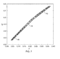
- Figure 7 shows the initial aerofoil section 48 and the recambered aerofoil section 72.
- the pressure surface 44 and suction surface 46 of the recambered aerofoil section 72 are smooth, having no kink or other discontinuity as generated by known methods of recambering aerofoils 36.
- the method of the present invention should preferably be refined to set a camber point 52 on the stacking axis 38. There should then be a criterion applied so that the stacking axis camber point 74 cannot be displaced during the recalculation of the camber line 50. This guarantees that the array of aerofoil sections 48 will form a continuous, three-dimensional, aerofoil 36 after application of the method. It can be seen in Figure 7 that the stacking axis camber point 74 is unchanged between the initial aerofoil section 48 and the recambered aerofoil section 72.
- the method of the present invention is preferably encompassed in computer-implemented code and stored on a computer-readable medium. It is thus a computer-implemented method of recambering an aerofoil section.
- the method may be implemented on a basic computer system comprising a processing unit, memory, user interface means such as a keyboard and/or mouse, and display means.
- the method is a design method which is performed 'offline' starting from a previous aerofoil design.
- the first step of the method has been described as determining the intersection point 58 on the suction surface 46, the method is also applicable where the intersection point 76 (not shown) between the passage shock 56 and the pressure surface 44 is found. It is generally more beneficial to use the method to determine the intersection point 58 on the suction surface 46 because the passage shock 56 just touches the leading edge 40 of the aerofoil 36 on the pressure surface 44 and so the problems of discontinuities in the pressure loading are small or non-existent. However, in some applications the passage shock 56 may intersect with the pressure surface 44 away from the leading edge 40 of the aerofoil 36 and such discontinuities will be present.
- the method can also be performed by finding the intersection point 58 on the suction surface 46 and the intersection point 76 on the pressure surface 44. Each of these is projected onto the camber line 50 to give shock positions 60. A shock region 62 encompassing each shock position 60 is then determined. The shock regions 62 may overlap, in which case they appear as one larger shock region 62 that may be asymmetric. Alternatively the shock regions 62 may be spaced apart, in which case there are three camber line regions: an upstream region 65, a downstream region 69 and an intermediate region 78 (not shown) between the two shock regions 62.
- the method then proceeds to recalculate the camber line 50 in the upstream region 65, project the camber line 50 across the first shock region 62, recalculate the camber line 50 in the intermediate region 78, project the camber line 50 across the second shock region 62 and finally recalculate the camber line 50 in the downstream region 69.
- the method of the present invention is also applicable to other aerofoils that experience transonic flow, and therefore shocks.
- Such aerofoils comprise aircraft wings; propeller gas turbine engine blades; helicopter and aircraft propellers; gas turbine engines for aircraft, marine and industrial applications; compressor stages in turbochargers; radial flow impellers for gas pumping applications; and steam turbines for power generation applications.
Landscapes
- Engineering & Computer Science (AREA)
- Physics & Mathematics (AREA)
- Theoretical Computer Science (AREA)
- General Engineering & Computer Science (AREA)
- General Physics & Mathematics (AREA)
- Computer Hardware Design (AREA)
- Evolutionary Computation (AREA)
- Geometry (AREA)
- Mechanical Engineering (AREA)
- Fluid Mechanics (AREA)
- Algebra (AREA)
- Computing Systems (AREA)
- Mathematical Analysis (AREA)
- Mathematical Optimization (AREA)
- Mathematical Physics (AREA)
- Pure & Applied Mathematics (AREA)
- Structures Of Non-Positive Displacement Pumps (AREA)
- Turbine Rotor Nozzle Sealing (AREA)
- Architecture (AREA)
- Software Systems (AREA)
Applications Claiming Priority (1)
| Application Number | Priority Date | Filing Date | Title |
|---|---|---|---|
| GBGB1309280.4A GB201309280D0 (en) | 2013-05-23 | 2013-05-23 | Aerofoil Recambering |
Publications (2)
| Publication Number | Publication Date |
|---|---|
| EP2806104A1 true EP2806104A1 (de) | 2014-11-26 |
| EP2806104B1 EP2806104B1 (de) | 2017-03-15 |
Family
ID=48784616
Family Applications (1)
| Application Number | Title | Priority Date | Filing Date |
|---|---|---|---|
| EP14166295.7A Not-in-force EP2806104B1 (de) | 2013-05-23 | 2014-04-29 | Wölbungsveränderung eines Schaufelprofils |
Country Status (3)
| Country | Link |
|---|---|
| US (1) | US9965571B2 (de) |
| EP (1) | EP2806104B1 (de) |
| GB (1) | GB201309280D0 (de) |
Cited By (1)
| Publication number | Priority date | Publication date | Assignee | Title |
|---|---|---|---|---|
| CN106762762A (zh) * | 2016-12-08 | 2017-05-31 | 沈阳黎明航空发动机(集团)有限责任公司 | 航空发动机导向叶片模拟工作状况的检查系统及方法 |
Families Citing this family (3)
| Publication number | Priority date | Publication date | Assignee | Title |
|---|---|---|---|---|
| EP3088663A1 (de) * | 2015-04-28 | 2016-11-02 | Siemens Aktiengesellschaft | Verfahren zum profilieren einer schaufel |
| EP3239460A1 (de) * | 2016-04-27 | 2017-11-01 | Siemens Aktiengesellschaft | Verfahren zum profilieren von schaufeln einer axialströmungsmaschine |
| CN117332532B (zh) * | 2023-12-01 | 2024-03-08 | 陕西空天信息技术有限公司 | 一种轴流叶轮机械叶片模型构建方法及装置 |
Citations (1)
| Publication number | Priority date | Publication date | Assignee | Title |
|---|---|---|---|---|
| EP1742160A1 (de) * | 2005-07-08 | 2007-01-10 | Ansaldo Energia S.P.A. | Verfahren zum Optimieren von Flügelprofilen |
Family Cites Families (4)
| Publication number | Priority date | Publication date | Assignee | Title |
|---|---|---|---|---|
| WO2010032240A2 (en) * | 2008-09-17 | 2010-03-25 | Israel Aerospace Industries Ltd. | Aerofoils |
| US20110182741A1 (en) * | 2010-01-26 | 2011-07-28 | United Technologies Corporation | Composite fan blade leading edge recamber |
| WO2013054404A1 (ja) * | 2011-10-12 | 2013-04-18 | 三菱重工業株式会社 | 風車翼及びこれを備えた風力発電装置ならびに風車翼の設計方法 |
| CN103047079B (zh) | 2012-12-22 | 2015-04-22 | 中国科学院工程热物理研究所 | 一种高效低载水平轴风力机叶片专用翼型及其设计方法 |
-
2013
- 2013-05-23 GB GBGB1309280.4A patent/GB201309280D0/en not_active Ceased
-
2014
- 2014-04-29 EP EP14166295.7A patent/EP2806104B1/de not_active Not-in-force
- 2014-04-30 US US14/265,843 patent/US9965571B2/en not_active Expired - Fee Related
Patent Citations (1)
| Publication number | Priority date | Publication date | Assignee | Title |
|---|---|---|---|---|
| EP1742160A1 (de) * | 2005-07-08 | 2007-01-10 | Ansaldo Energia S.P.A. | Verfahren zum Optimieren von Flügelprofilen |
Non-Patent Citations (2)
| Title |
|---|
| JINGUANG YANG ET AL: "The development and application of an inviscid inverse method", PROPULSION AND POWER RESEARCH, vol. 2, no. 2, 22 May 2013 (2013-05-22), pages 131 - 138, XP055143472, ISSN: 2212-540X, [retrieved on 20140930], DOI: 10.1016/j.jppr.2013.04.005 * |
| RAJA RAMAMURTHY ET AL: "A VISCOUS INVERSE DESIGN METHOD FOR INTERNAL AND EXTERNAL FLOW OVER AIRFOIS USING CFD TECHNIQUES", V EUROPEAN CONFERENCE ON COMPUTATIONAL FLUID DYNAMICS ECCOMAS CFD 2010, 17 June 2010 (2010-06-17), pages 14 - 17, XP055143477, Retrieved from the Internet <URL:http://congress.cimne.com/eccomas/cfd2010/papers/01058.pdf> [retrieved on 20140930] * |
Cited By (1)
| Publication number | Priority date | Publication date | Assignee | Title |
|---|---|---|---|---|
| CN106762762A (zh) * | 2016-12-08 | 2017-05-31 | 沈阳黎明航空发动机(集团)有限责任公司 | 航空发动机导向叶片模拟工作状况的检查系统及方法 |
Also Published As
| Publication number | Publication date |
|---|---|
| US20140348648A1 (en) | 2014-11-27 |
| EP2806104B1 (de) | 2017-03-15 |
| GB201309280D0 (en) | 2013-07-10 |
| US9965571B2 (en) | 2018-05-08 |
Similar Documents
| Publication | Publication Date | Title |
|---|---|---|
| CN105122248B (zh) | 用于对部件尤其是涡轮叶片进行建模的方法 | |
| CN102562178B (zh) | 用于空气循环机的涡轮机喷嘴 | |
| EP3029270B1 (de) | Turbomaschinen-schaufeln und verfahren zur verminderung des schaufelflatterns | |
| Siddappaji et al. | General capability of parametric 3d blade design tool for turbomachinery | |
| EP3118412B1 (de) | Verfahren zur erzeugung einer schaufel mit einer aerodynamisch geformten ausrundung und schaufel mit der aerodynamisch geformten ausrundung | |
| JP6708995B2 (ja) | 軸流流体機械の翼の設計方法及び翼 | |
| US10387611B2 (en) | Method for modeling a blade of a non-ducted propeller | |
| Korakianitis | Prescribed-curvature-distribution airfoils for the preliminary geometric design of axial-turbomachinery cascades | |
| Korakianitis et al. | Design of high-efficiency turbomachinery blades for energy conversion devices with the three-dimensional prescribed surface curvature distribution blade design (CIRCLE) method | |
| Nemnem et al. | A smooth curvature-defined meanline section option for a general turbomachinery geometry generator | |
| WO2019011395A1 (en) | AIR WING WITH AT LEAST TWO MARGINAL FINS | |
| EP2806104B1 (de) | Wölbungsveränderung eines Schaufelprofils | |
| Carolus et al. | An aerodynamic design methodology for low pressure axial fans with integrated airfoil polar prediction | |
| Wellborn et al. | Bleed flow interactions with an axial-flow compressor powerstream | |
| CN110030038B (zh) | 考虑bli进气畸变效应的叶尖跨音风扇非对称静子设计方法 | |
| Power et al. | Numerical and experimental findings of a highly-loaded aspirated cascade | |
| Kim et al. | Mail-slot nacelle shape design for N3-X hybrid wing-body configuration | |
| Korakianitis et al. | Improved turbine-blade design techniques using 4th-order parametric-spline segments | |
| Li et al. | Aerodynamic design and optimization of a high-loaded axial fan stage using a curvature control method | |
| He et al. | Investigation of vaned diffuser splitters on the performance and flow control of high pressure ratio centrifugal compressors | |
| Page et al. | Inverse design of 3D multi-stage transonic fans at dual operating points | |
| US9784286B2 (en) | Flutter-resistant turbomachinery blades | |
| McGlumphy et al. | Numerical investigation of tandem airfoils for subsonic axial-flow compressor blades | |
| EP3263837A1 (de) | Axialkompressorbeschaufelung mit druckrückgewinnung | |
| Vikhorev et al. | The influence of the vane lean on the flow in a turbine rear structure |
Legal Events
| Date | Code | Title | Description |
|---|---|---|---|
| PUAI | Public reference made under article 153(3) epc to a published international application that has entered the european phase |
Free format text: ORIGINAL CODE: 0009012 |
|
| 17P | Request for examination filed |
Effective date: 20140429 |
|
| AK | Designated contracting states |
Kind code of ref document: A1 Designated state(s): AL AT BE BG CH CY CZ DE DK EE ES FI FR GB GR HR HU IE IS IT LI LT LU LV MC MK MT NL NO PL PT RO RS SE SI SK SM TR |
|
| AX | Request for extension of the european patent |
Extension state: BA ME |
|
| R17P | Request for examination filed (corrected) |
Effective date: 20150413 |
|
| RBV | Designated contracting states (corrected) |
Designated state(s): AL AT BE BG CH CY CZ DE DK EE ES FI FR GB GR HR HU IE IS IT LI LT LU LV MC MK MT NL NO PL PT RO RS SE SI SK SM TR |
|
| RAP1 | Party data changed (applicant data changed or rights of an application transferred) |
Owner name: ROLLS-ROYCE PLC |
|
| REG | Reference to a national code |
Ref country code: DE Ref legal event code: R079 Ref document number: 602014007508 Country of ref document: DE Free format text: PREVIOUS MAIN CLASS: F01D0005140000 Ipc: F01D0009020000 |
|
| GRAP | Despatch of communication of intention to grant a patent |
Free format text: ORIGINAL CODE: EPIDOSNIGR1 |
|
| STAA | Information on the status of an ep patent application or granted ep patent |
Free format text: STATUS: GRANT OF PATENT IS INTENDED |
|
| RIC1 | Information provided on ipc code assigned before grant |
Ipc: F01D 9/02 20060101AFI20161208BHEP Ipc: F01D 5/14 20060101ALI20161208BHEP Ipc: G06F 17/50 20060101ALI20161208BHEP |
|
| INTG | Intention to grant announced |
Effective date: 20170109 |
|
| RIN1 | Information on inventor provided before grant (corrected) |
Inventor name: PAGE, JAMES Inventor name: TUCKER, PAUL Inventor name: HIELD, PAUL |
|
| GRAS | Grant fee paid |
Free format text: ORIGINAL CODE: EPIDOSNIGR3 |
|
| GRAA | (expected) grant |
Free format text: ORIGINAL CODE: 0009210 |
|
| STAA | Information on the status of an ep patent application or granted ep patent |
Free format text: STATUS: THE PATENT HAS BEEN GRANTED |
|
| AK | Designated contracting states |
Kind code of ref document: B1 Designated state(s): AL AT BE BG CH CY CZ DE DK EE ES FI FR GB GR HR HU IE IS IT LI LT LU LV MC MK MT NL NO PL PT RO RS SE SI SK SM TR |
|
| REG | Reference to a national code |
Ref country code: CH Ref legal event code: EP Ref country code: GB Ref legal event code: FG4D |
|
| REG | Reference to a national code |
Ref country code: IE Ref legal event code: FG4D |
|
| REG | Reference to a national code |
Ref country code: AT Ref legal event code: REF Ref document number: 875809 Country of ref document: AT Kind code of ref document: T Effective date: 20170415 |
|
| REG | Reference to a national code |
Ref country code: FR Ref legal event code: PLFP Year of fee payment: 4 |
|
| REG | Reference to a national code |
Ref country code: DE Ref legal event code: R096 Ref document number: 602014007508 Country of ref document: DE |
|
| REG | Reference to a national code |
Ref country code: NL Ref legal event code: MP Effective date: 20170315 |
|
| REG | Reference to a national code |
Ref country code: LT Ref legal event code: MG4D |
|
| PG25 | Lapsed in a contracting state [announced via postgrant information from national office to epo] |
Ref country code: FI Free format text: LAPSE BECAUSE OF FAILURE TO SUBMIT A TRANSLATION OF THE DESCRIPTION OR TO PAY THE FEE WITHIN THE PRESCRIBED TIME-LIMIT Effective date: 20170315 Ref country code: HR Free format text: LAPSE BECAUSE OF FAILURE TO SUBMIT A TRANSLATION OF THE DESCRIPTION OR TO PAY THE FEE WITHIN THE PRESCRIBED TIME-LIMIT Effective date: 20170315 Ref country code: LT Free format text: LAPSE BECAUSE OF FAILURE TO SUBMIT A TRANSLATION OF THE DESCRIPTION OR TO PAY THE FEE WITHIN THE PRESCRIBED TIME-LIMIT Effective date: 20170315 Ref country code: NO Free format text: LAPSE BECAUSE OF FAILURE TO SUBMIT A TRANSLATION OF THE DESCRIPTION OR TO PAY THE FEE WITHIN THE PRESCRIBED TIME-LIMIT Effective date: 20170615 Ref country code: GR Free format text: LAPSE BECAUSE OF FAILURE TO SUBMIT A TRANSLATION OF THE DESCRIPTION OR TO PAY THE FEE WITHIN THE PRESCRIBED TIME-LIMIT Effective date: 20170616 |
|
| REG | Reference to a national code |
Ref country code: AT Ref legal event code: MK05 Ref document number: 875809 Country of ref document: AT Kind code of ref document: T Effective date: 20170315 |
|
| PG25 | Lapsed in a contracting state [announced via postgrant information from national office to epo] |
Ref country code: BG Free format text: LAPSE BECAUSE OF FAILURE TO SUBMIT A TRANSLATION OF THE DESCRIPTION OR TO PAY THE FEE WITHIN THE PRESCRIBED TIME-LIMIT Effective date: 20170615 Ref country code: LV Free format text: LAPSE BECAUSE OF FAILURE TO SUBMIT A TRANSLATION OF THE DESCRIPTION OR TO PAY THE FEE WITHIN THE PRESCRIBED TIME-LIMIT Effective date: 20170315 Ref country code: SE Free format text: LAPSE BECAUSE OF FAILURE TO SUBMIT A TRANSLATION OF THE DESCRIPTION OR TO PAY THE FEE WITHIN THE PRESCRIBED TIME-LIMIT Effective date: 20170315 Ref country code: RS Free format text: LAPSE BECAUSE OF FAILURE TO SUBMIT A TRANSLATION OF THE DESCRIPTION OR TO PAY THE FEE WITHIN THE PRESCRIBED TIME-LIMIT Effective date: 20170315 |
|
| PG25 | Lapsed in a contracting state [announced via postgrant information from national office to epo] |
Ref country code: NL Free format text: LAPSE BECAUSE OF FAILURE TO SUBMIT A TRANSLATION OF THE DESCRIPTION OR TO PAY THE FEE WITHIN THE PRESCRIBED TIME-LIMIT Effective date: 20170315 |
|
| PG25 | Lapsed in a contracting state [announced via postgrant information from national office to epo] |
Ref country code: CZ Free format text: LAPSE BECAUSE OF FAILURE TO SUBMIT A TRANSLATION OF THE DESCRIPTION OR TO PAY THE FEE WITHIN THE PRESCRIBED TIME-LIMIT Effective date: 20170315 Ref country code: SK Free format text: LAPSE BECAUSE OF FAILURE TO SUBMIT A TRANSLATION OF THE DESCRIPTION OR TO PAY THE FEE WITHIN THE PRESCRIBED TIME-LIMIT Effective date: 20170315 Ref country code: EE Free format text: LAPSE BECAUSE OF FAILURE TO SUBMIT A TRANSLATION OF THE DESCRIPTION OR TO PAY THE FEE WITHIN THE PRESCRIBED TIME-LIMIT Effective date: 20170315 Ref country code: IT Free format text: LAPSE BECAUSE OF FAILURE TO SUBMIT A TRANSLATION OF THE DESCRIPTION OR TO PAY THE FEE WITHIN THE PRESCRIBED TIME-LIMIT Effective date: 20170315 Ref country code: ES Free format text: LAPSE BECAUSE OF FAILURE TO SUBMIT A TRANSLATION OF THE DESCRIPTION OR TO PAY THE FEE WITHIN THE PRESCRIBED TIME-LIMIT Effective date: 20170315 Ref country code: RO Free format text: LAPSE BECAUSE OF FAILURE TO SUBMIT A TRANSLATION OF THE DESCRIPTION OR TO PAY THE FEE WITHIN THE PRESCRIBED TIME-LIMIT Effective date: 20170315 Ref country code: AT Free format text: LAPSE BECAUSE OF FAILURE TO SUBMIT A TRANSLATION OF THE DESCRIPTION OR TO PAY THE FEE WITHIN THE PRESCRIBED TIME-LIMIT Effective date: 20170315 |
|
| PG25 | Lapsed in a contracting state [announced via postgrant information from national office to epo] |
Ref country code: SM Free format text: LAPSE BECAUSE OF FAILURE TO SUBMIT A TRANSLATION OF THE DESCRIPTION OR TO PAY THE FEE WITHIN THE PRESCRIBED TIME-LIMIT Effective date: 20170315 Ref country code: IS Free format text: LAPSE BECAUSE OF FAILURE TO SUBMIT A TRANSLATION OF THE DESCRIPTION OR TO PAY THE FEE WITHIN THE PRESCRIBED TIME-LIMIT Effective date: 20170715 Ref country code: PT Free format text: LAPSE BECAUSE OF FAILURE TO SUBMIT A TRANSLATION OF THE DESCRIPTION OR TO PAY THE FEE WITHIN THE PRESCRIBED TIME-LIMIT Effective date: 20170717 Ref country code: PL Free format text: LAPSE BECAUSE OF FAILURE TO SUBMIT A TRANSLATION OF THE DESCRIPTION OR TO PAY THE FEE WITHIN THE PRESCRIBED TIME-LIMIT Effective date: 20170315 |
|
| REG | Reference to a national code |
Ref country code: CH Ref legal event code: PL |
|
| REG | Reference to a national code |
Ref country code: DE Ref legal event code: R097 Ref document number: 602014007508 Country of ref document: DE |
|
| PLBE | No opposition filed within time limit |
Free format text: ORIGINAL CODE: 0009261 |
|
| STAA | Information on the status of an ep patent application or granted ep patent |
Free format text: STATUS: NO OPPOSITION FILED WITHIN TIME LIMIT |
|
| REG | Reference to a national code |
Ref country code: IE Ref legal event code: MM4A |
|
| PG25 | Lapsed in a contracting state [announced via postgrant information from national office to epo] |
Ref country code: DK Free format text: LAPSE BECAUSE OF FAILURE TO SUBMIT A TRANSLATION OF THE DESCRIPTION OR TO PAY THE FEE WITHIN THE PRESCRIBED TIME-LIMIT Effective date: 20170315 Ref country code: MC Free format text: LAPSE BECAUSE OF FAILURE TO SUBMIT A TRANSLATION OF THE DESCRIPTION OR TO PAY THE FEE WITHIN THE PRESCRIBED TIME-LIMIT Effective date: 20170315 |
|
| 26N | No opposition filed |
Effective date: 20171218 |
|
| PG25 | Lapsed in a contracting state [announced via postgrant information from national office to epo] |
Ref country code: CH Free format text: LAPSE BECAUSE OF NON-PAYMENT OF DUE FEES Effective date: 20170430 Ref country code: LU Free format text: LAPSE BECAUSE OF NON-PAYMENT OF DUE FEES Effective date: 20170429 Ref country code: SI Free format text: LAPSE BECAUSE OF FAILURE TO SUBMIT A TRANSLATION OF THE DESCRIPTION OR TO PAY THE FEE WITHIN THE PRESCRIBED TIME-LIMIT Effective date: 20170315 Ref country code: LI Free format text: LAPSE BECAUSE OF NON-PAYMENT OF DUE FEES Effective date: 20170430 |
|
| REG | Reference to a national code |
Ref country code: BE Ref legal event code: MM Effective date: 20170430 |
|
| REG | Reference to a national code |
Ref country code: FR Ref legal event code: PLFP Year of fee payment: 5 |
|
| PG25 | Lapsed in a contracting state [announced via postgrant information from national office to epo] |
Ref country code: IE Free format text: LAPSE BECAUSE OF NON-PAYMENT OF DUE FEES Effective date: 20170429 |
|
| PG25 | Lapsed in a contracting state [announced via postgrant information from national office to epo] |
Ref country code: BE Free format text: LAPSE BECAUSE OF NON-PAYMENT OF DUE FEES Effective date: 20170430 |
|
| PG25 | Lapsed in a contracting state [announced via postgrant information from national office to epo] |
Ref country code: MT Free format text: LAPSE BECAUSE OF NON-PAYMENT OF DUE FEES Effective date: 20170429 |
|
| PG25 | Lapsed in a contracting state [announced via postgrant information from national office to epo] |
Ref country code: HU Free format text: LAPSE BECAUSE OF FAILURE TO SUBMIT A TRANSLATION OF THE DESCRIPTION OR TO PAY THE FEE WITHIN THE PRESCRIBED TIME-LIMIT; INVALID AB INITIO Effective date: 20140429 |
|
| PGFP | Annual fee paid to national office [announced via postgrant information from national office to epo] |
Ref country code: DE Payment date: 20190429 Year of fee payment: 6 |
|
| PGFP | Annual fee paid to national office [announced via postgrant information from national office to epo] |
Ref country code: FR Payment date: 20190425 Year of fee payment: 6 |
|
| PG25 | Lapsed in a contracting state [announced via postgrant information from national office to epo] |
Ref country code: CY Free format text: LAPSE BECAUSE OF FAILURE TO SUBMIT A TRANSLATION OF THE DESCRIPTION OR TO PAY THE FEE WITHIN THE PRESCRIBED TIME-LIMIT Effective date: 20170315 |
|
| PGFP | Annual fee paid to national office [announced via postgrant information from national office to epo] |
Ref country code: GB Payment date: 20190429 Year of fee payment: 6 |
|
| PG25 | Lapsed in a contracting state [announced via postgrant information from national office to epo] |
Ref country code: MK Free format text: LAPSE BECAUSE OF FAILURE TO SUBMIT A TRANSLATION OF THE DESCRIPTION OR TO PAY THE FEE WITHIN THE PRESCRIBED TIME-LIMIT Effective date: 20170315 |
|
| PG25 | Lapsed in a contracting state [announced via postgrant information from national office to epo] |
Ref country code: TR Free format text: LAPSE BECAUSE OF FAILURE TO SUBMIT A TRANSLATION OF THE DESCRIPTION OR TO PAY THE FEE WITHIN THE PRESCRIBED TIME-LIMIT Effective date: 20170315 |
|
| PG25 | Lapsed in a contracting state [announced via postgrant information from national office to epo] |
Ref country code: AL Free format text: LAPSE BECAUSE OF FAILURE TO SUBMIT A TRANSLATION OF THE DESCRIPTION OR TO PAY THE FEE WITHIN THE PRESCRIBED TIME-LIMIT Effective date: 20170315 |
|
| REG | Reference to a national code |
Ref country code: DE Ref legal event code: R119 Ref document number: 602014007508 Country of ref document: DE |
|
| PG25 | Lapsed in a contracting state [announced via postgrant information from national office to epo] |
Ref country code: DE Free format text: LAPSE BECAUSE OF NON-PAYMENT OF DUE FEES Effective date: 20201103 Ref country code: FR Free format text: LAPSE BECAUSE OF NON-PAYMENT OF DUE FEES Effective date: 20200430 |
|
| GBPC | Gb: european patent ceased through non-payment of renewal fee |
Effective date: 20200429 |
|
| PG25 | Lapsed in a contracting state [announced via postgrant information from national office to epo] |
Ref country code: GB Free format text: LAPSE BECAUSE OF NON-PAYMENT OF DUE FEES Effective date: 20200429 |