EP2805909A1 - Dispositif de chauffage - Google Patents
Dispositif de chauffage Download PDFInfo
- Publication number
- EP2805909A1 EP2805909A1 EP14180218.1A EP14180218A EP2805909A1 EP 2805909 A1 EP2805909 A1 EP 2805909A1 EP 14180218 A EP14180218 A EP 14180218A EP 2805909 A1 EP2805909 A1 EP 2805909A1
- Authority
- EP
- European Patent Office
- Prior art keywords
- tower
- tower segment
- segment
- centering
- ladder
- Prior art date
- Legal status (The legal status is an assumption and is not a legal conclusion. Google has not performed a legal analysis and makes no representation as to the accuracy of the status listed.)
- Granted
Links
- 238000010438 heat treatment Methods 0.000 title claims abstract description 27
- 238000010276 construction Methods 0.000 claims abstract description 15
- 238000000034 method Methods 0.000 claims abstract description 10
- 230000002093 peripheral effect Effects 0.000 claims description 2
- 229910000831 Steel Inorganic materials 0.000 description 18
- 239000010959 steel Substances 0.000 description 18
- 239000000463 material Substances 0.000 description 6
- 238000005266 casting Methods 0.000 description 5
- 150000001875 compounds Chemical class 0.000 description 4
- 239000004020 conductor Substances 0.000 description 4
- 230000008014 freezing Effects 0.000 description 4
- 238000007710 freezing Methods 0.000 description 4
- 238000003780 insertion Methods 0.000 description 4
- 230000037431 insertion Effects 0.000 description 4
- 239000002184 metal Substances 0.000 description 3
- 239000000243 solution Substances 0.000 description 3
- 230000033228 biological regulation Effects 0.000 description 2
- 230000000903 blocking effect Effects 0.000 description 2
- 238000009434 installation Methods 0.000 description 2
- 238000004519 manufacturing process Methods 0.000 description 2
- 210000003205 muscle Anatomy 0.000 description 2
- 229920000642 polymer Polymers 0.000 description 2
- 208000034656 Contusions Diseases 0.000 description 1
- 208000027418 Wounds and injury Diseases 0.000 description 1
- 230000006978 adaptation Effects 0.000 description 1
- 238000013270 controlled release Methods 0.000 description 1
- 230000006378 damage Effects 0.000 description 1
- 230000001934 delay Effects 0.000 description 1
- 238000006073 displacement reaction Methods 0.000 description 1
- 230000000694 effects Effects 0.000 description 1
- 230000002349 favourable effect Effects 0.000 description 1
- 210000003128 head Anatomy 0.000 description 1
- 230000001771 impaired effect Effects 0.000 description 1
- 238000001746 injection moulding Methods 0.000 description 1
- 208000014674 injury Diseases 0.000 description 1
- 230000013011 mating Effects 0.000 description 1
- 230000002265 prevention Effects 0.000 description 1
- 230000002035 prolonged effect Effects 0.000 description 1
- 230000001681 protective effect Effects 0.000 description 1
- 230000005855 radiation Effects 0.000 description 1
- 230000000284 resting effect Effects 0.000 description 1
- 238000000926 separation method Methods 0.000 description 1
- 230000006641 stabilisation Effects 0.000 description 1
- 238000011105 stabilization Methods 0.000 description 1
- 238000003860 storage Methods 0.000 description 1
Images


Classifications
-
- E—FIXED CONSTRUCTIONS
- E04—BUILDING
- E04H—BUILDINGS OR LIKE STRUCTURES FOR PARTICULAR PURPOSES; SWIMMING OR SPLASH BATHS OR POOLS; MASTS; FENCING; TENTS OR CANOPIES, IN GENERAL
- E04H12/00—Towers; Masts or poles; Chimney stacks; Water-towers; Methods of erecting such structures
- E04H12/34—Arrangements for erecting or lowering towers, masts, poles, chimney stacks, or the like
- E04H12/342—Arrangements for stacking tower sections on top of each other
-
- F—MECHANICAL ENGINEERING; LIGHTING; HEATING; WEAPONS; BLASTING
- F16—ENGINEERING ELEMENTS AND UNITS; GENERAL MEASURES FOR PRODUCING AND MAINTAINING EFFECTIVE FUNCTIONING OF MACHINES OR INSTALLATIONS; THERMAL INSULATION IN GENERAL
- F16B—DEVICES FOR FASTENING OR SECURING CONSTRUCTIONAL ELEMENTS OR MACHINE PARTS TOGETHER, e.g. NAILS, BOLTS, CIRCLIPS, CLAMPS, CLIPS OR WEDGES; JOINTS OR JOINTING
- F16B19/00—Bolts without screw-thread; Pins, including deformable elements; Rivets
- F16B19/02—Bolts or sleeves for positioning of machine parts, e.g. notched taper pins, fitting pins, sleeves, eccentric positioning rings
-
- B—PERFORMING OPERATIONS; TRANSPORTING
- B66—HOISTING; LIFTING; HAULING
- B66B—ELEVATORS; ESCALATORS OR MOVING WALKWAYS
- B66B17/00—Hoistway equipment
- B66B17/08—Mining skips
- B66B17/10—Mining skips adapted for passenger transport
-
- B—PERFORMING OPERATIONS; TRANSPORTING
- B66—HOISTING; LIFTING; HAULING
- B66B—ELEVATORS; ESCALATORS OR MOVING WALKWAYS
- B66B19/00—Mining-hoist operation
-
- B—PERFORMING OPERATIONS; TRANSPORTING
- B66—HOISTING; LIFTING; HAULING
- B66B—ELEVATORS; ESCALATORS OR MOVING WALKWAYS
- B66B9/00—Kinds or types of lifts in, or associated with, buildings or other structures
- B66B9/16—Mobile or transportable lifts specially adapted to be shifted from one part of a building or other structure to another part or to another building or structure
- B66B9/187—Mobile or transportable lifts specially adapted to be shifted from one part of a building or other structure to another part or to another building or structure with a liftway specially adapted for temporary connection to a building or other structure
-
- B—PERFORMING OPERATIONS; TRANSPORTING
- B66—HOISTING; LIFTING; HAULING
- B66C—CRANES; LOAD-ENGAGING ELEMENTS OR DEVICES FOR CRANES, CAPSTANS, WINCHES, OR TACKLES
- B66C1/00—Load-engaging elements or devices attached to lifting or lowering gear of cranes or adapted for connection therewith for transmitting lifting forces to articles or groups of articles
- B66C1/10—Load-engaging elements or devices attached to lifting or lowering gear of cranes or adapted for connection therewith for transmitting lifting forces to articles or groups of articles by mechanical means
- B66C1/108—Load-engaging elements or devices attached to lifting or lowering gear of cranes or adapted for connection therewith for transmitting lifting forces to articles or groups of articles by mechanical means for lifting parts of wind turbines
-
- B—PERFORMING OPERATIONS; TRANSPORTING
- B66—HOISTING; LIFTING; HAULING
- B66C—CRANES; LOAD-ENGAGING ELEMENTS OR DEVICES FOR CRANES, CAPSTANS, WINCHES, OR TACKLES
- B66C23/00—Cranes comprising essentially a beam, boom, or triangular structure acting as a cantilever and mounted for translatory of swinging movements in vertical or horizontal planes or a combination of such movements, e.g. jib-cranes, derricks, tower cranes
- B66C23/16—Cranes comprising essentially a beam, boom, or triangular structure acting as a cantilever and mounted for translatory of swinging movements in vertical or horizontal planes or a combination of such movements, e.g. jib-cranes, derricks, tower cranes with jibs supported by columns, e.g. towers having their lower end mounted for slewing movements
-
- E—FIXED CONSTRUCTIONS
- E04—BUILDING
- E04B—GENERAL BUILDING CONSTRUCTIONS; WALLS, e.g. PARTITIONS; ROOFS; FLOORS; CEILINGS; INSULATION OR OTHER PROTECTION OF BUILDINGS
- E04B1/00—Constructions in general; Structures which are not restricted either to walls, e.g. partitions, or floors or ceilings or roofs
- E04B1/02—Structures consisting primarily of load-supporting, block-shaped, or slab-shaped elements
- E04B1/04—Structures consisting primarily of load-supporting, block-shaped, or slab-shaped elements the elements consisting of concrete, e.g. reinforced concrete, or other stone-like material
-
- E—FIXED CONSTRUCTIONS
- E04—BUILDING
- E04G—SCAFFOLDING; FORMS; SHUTTERING; BUILDING IMPLEMENTS OR AIDS, OR THEIR USE; HANDLING BUILDING MATERIALS ON THE SITE; REPAIRING, BREAKING-UP OR OTHER WORK ON EXISTING BUILDINGS
- E04G21/00—Preparing, conveying, or working-up building materials or building elements in situ; Other devices or measures for constructional work
- E04G21/14—Conveying or assembling building elements
- E04G21/142—Means in or on the elements for connecting same to handling apparatus
-
- E—FIXED CONSTRUCTIONS
- E04—BUILDING
- E04G—SCAFFOLDING; FORMS; SHUTTERING; BUILDING IMPLEMENTS OR AIDS, OR THEIR USE; HANDLING BUILDING MATERIALS ON THE SITE; REPAIRING, BREAKING-UP OR OTHER WORK ON EXISTING BUILDINGS
- E04G21/00—Preparing, conveying, or working-up building materials or building elements in situ; Other devices or measures for constructional work
- E04G21/24—Safety or protective measures preventing damage to building parts or finishing work during construction
-
- E—FIXED CONSTRUCTIONS
- E04—BUILDING
- E04G—SCAFFOLDING; FORMS; SHUTTERING; BUILDING IMPLEMENTS OR AIDS, OR THEIR USE; HANDLING BUILDING MATERIALS ON THE SITE; REPAIRING, BREAKING-UP OR OTHER WORK ON EXISTING BUILDINGS
- E04G3/00—Scaffolds essentially supported by building constructions, e.g. adjustable in height
- E04G3/24—Scaffolds essentially supported by building constructions, e.g. adjustable in height specially adapted for particular parts of buildings or for buildings of particular shape, e.g. chimney stacks or pylons
- E04G3/246—Scaffolds essentially supported by building constructions, e.g. adjustable in height specially adapted for particular parts of buildings or for buildings of particular shape, e.g. chimney stacks or pylons following the inside contour of a building
-
- E—FIXED CONSTRUCTIONS
- E04—BUILDING
- E04H—BUILDINGS OR LIKE STRUCTURES FOR PARTICULAR PURPOSES; SWIMMING OR SPLASH BATHS OR POOLS; MASTS; FENCING; TENTS OR CANOPIES, IN GENERAL
- E04H12/00—Towers; Masts or poles; Chimney stacks; Water-towers; Methods of erecting such structures
- E04H12/02—Structures made of specified materials
- E04H12/12—Structures made of specified materials of concrete or other stone-like material, with or without internal or external reinforcements, e.g. with metal coverings, with permanent form elements
-
- E—FIXED CONSTRUCTIONS
- E04—BUILDING
- E04H—BUILDINGS OR LIKE STRUCTURES FOR PARTICULAR PURPOSES; SWIMMING OR SPLASH BATHS OR POOLS; MASTS; FENCING; TENTS OR CANOPIES, IN GENERAL
- E04H12/00—Towers; Masts or poles; Chimney stacks; Water-towers; Methods of erecting such structures
- E04H12/34—Arrangements for erecting or lowering towers, masts, poles, chimney stacks, or the like
-
- E—FIXED CONSTRUCTIONS
- E06—DOORS, WINDOWS, SHUTTERS, OR ROLLER BLINDS IN GENERAL; LADDERS
- E06C—LADDERS
- E06C7/00—Component parts, supporting parts, or accessories
- E06C7/12—Lifts or other hoisting devices on ladders
-
- E—FIXED CONSTRUCTIONS
- E06—DOORS, WINDOWS, SHUTTERS, OR ROLLER BLINDS IN GENERAL; LADDERS
- E06C—LADDERS
- E06C7/00—Component parts, supporting parts, or accessories
- E06C7/16—Platforms on, or for use on, ladders, e.g. liftable or lowerable platforms
-
- E—FIXED CONSTRUCTIONS
- E06—DOORS, WINDOWS, SHUTTERS, OR ROLLER BLINDS IN GENERAL; LADDERS
- E06C—LADDERS
- E06C9/00—Ladders characterised by being permanently attached to fixed structures, e.g. fire escapes
- E06C9/02—Ladders characterised by being permanently attached to fixed structures, e.g. fire escapes rigidly mounted
-
- F—MECHANICAL ENGINEERING; LIGHTING; HEATING; WEAPONS; BLASTING
- F02—COMBUSTION ENGINES; HOT-GAS OR COMBUSTION-PRODUCT ENGINE PLANTS
- F02C—GAS-TURBINE PLANTS; AIR INTAKES FOR JET-PROPULSION PLANTS; CONTROLLING FUEL SUPPLY IN AIR-BREATHING JET-PROPULSION PLANTS
- F02C6/00—Plural gas-turbine plants; Combinations of gas-turbine plants with other apparatus; Adaptations of gas- turbine plants for special use
- F02C6/18—Plural gas-turbine plants; Combinations of gas-turbine plants with other apparatus; Adaptations of gas- turbine plants for special use using the waste heat of gas-turbine plants outside the plants themselves, e.g. gas-turbine power heat plants
-
- F—MECHANICAL ENGINEERING; LIGHTING; HEATING; WEAPONS; BLASTING
- F03—MACHINES OR ENGINES FOR LIQUIDS; WIND, SPRING, OR WEIGHT MOTORS; PRODUCING MECHANICAL POWER OR A REACTIVE PROPULSIVE THRUST, NOT OTHERWISE PROVIDED FOR
- F03D—WIND MOTORS
- F03D1/00—Wind motors with rotation axis substantially parallel to the air flow entering the rotor
-
- F—MECHANICAL ENGINEERING; LIGHTING; HEATING; WEAPONS; BLASTING
- F03—MACHINES OR ENGINES FOR LIQUIDS; WIND, SPRING, OR WEIGHT MOTORS; PRODUCING MECHANICAL POWER OR A REACTIVE PROPULSIVE THRUST, NOT OTHERWISE PROVIDED FOR
- F03D—WIND MOTORS
- F03D13/00—Assembly, mounting or commissioning of wind motors; Arrangements specially adapted for transporting wind motor components
- F03D13/10—Assembly of wind motors; Arrangements for erecting wind motors
-
- F—MECHANICAL ENGINEERING; LIGHTING; HEATING; WEAPONS; BLASTING
- F03—MACHINES OR ENGINES FOR LIQUIDS; WIND, SPRING, OR WEIGHT MOTORS; PRODUCING MECHANICAL POWER OR A REACTIVE PROPULSIVE THRUST, NOT OTHERWISE PROVIDED FOR
- F03D—WIND MOTORS
- F03D13/00—Assembly, mounting or commissioning of wind motors; Arrangements specially adapted for transporting wind motor components
- F03D13/20—Arrangements for mounting or supporting wind motors; Masts or towers for wind motors
-
- F—MECHANICAL ENGINEERING; LIGHTING; HEATING; WEAPONS; BLASTING
- F03—MACHINES OR ENGINES FOR LIQUIDS; WIND, SPRING, OR WEIGHT MOTORS; PRODUCING MECHANICAL POWER OR A REACTIVE PROPULSIVE THRUST, NOT OTHERWISE PROVIDED FOR
- F03D—WIND MOTORS
- F03D13/00—Assembly, mounting or commissioning of wind motors; Arrangements specially adapted for transporting wind motor components
- F03D13/40—Arrangements or methods specially adapted for transporting wind motor components
-
- F—MECHANICAL ENGINEERING; LIGHTING; HEATING; WEAPONS; BLASTING
- F24—HEATING; RANGES; VENTILATING
- F24H—FLUID HEATERS, e.g. WATER OR AIR HEATERS, HAVING HEAT-GENERATING MEANS, e.g. HEAT PUMPS, IN GENERAL
- F24H3/00—Air heaters
- F24H3/02—Air heaters with forced circulation
-
- E—FIXED CONSTRUCTIONS
- E06—DOORS, WINDOWS, SHUTTERS, OR ROLLER BLINDS IN GENERAL; LADDERS
- E06C—LADDERS
- E06C1/00—Ladders in general
- E06C1/02—Ladders in general with rigid longitudinal member or members
- E06C1/38—Special constructions of ladders, e.g. ladders with more or less than two longitudinal members, ladders with movable rungs or other treads, longitudinally-foldable ladders
- E06C1/381—Ladders with rungs or treads attached only to one rigid longitudinal member
-
- F—MECHANICAL ENGINEERING; LIGHTING; HEATING; WEAPONS; BLASTING
- F03—MACHINES OR ENGINES FOR LIQUIDS; WIND, SPRING, OR WEIGHT MOTORS; PRODUCING MECHANICAL POWER OR A REACTIVE PROPULSIVE THRUST, NOT OTHERWISE PROVIDED FOR
- F03D—WIND MOTORS
- F03D80/00—Details, components or accessories not provided for in groups F03D1/00 - F03D17/00
-
- F—MECHANICAL ENGINEERING; LIGHTING; HEATING; WEAPONS; BLASTING
- F05—INDEXING SCHEMES RELATING TO ENGINES OR PUMPS IN VARIOUS SUBCLASSES OF CLASSES F01-F04
- F05B—INDEXING SCHEME RELATING TO WIND, SPRING, WEIGHT, INERTIA OR LIKE MOTORS, TO MACHINES OR ENGINES FOR LIQUIDS COVERED BY SUBCLASSES F03B, F03D AND F03G
- F05B2230/00—Manufacture
- F05B2230/60—Assembly methods
- F05B2230/61—Assembly methods using auxiliary equipment for lifting or holding
-
- F—MECHANICAL ENGINEERING; LIGHTING; HEATING; WEAPONS; BLASTING
- F05—INDEXING SCHEMES RELATING TO ENGINES OR PUMPS IN VARIOUS SUBCLASSES OF CLASSES F01-F04
- F05D—INDEXING SCHEME FOR ASPECTS RELATING TO NON-POSITIVE-DISPLACEMENT MACHINES OR ENGINES, GAS-TURBINES OR JET-PROPULSION PLANTS
- F05D2220/00—Application
- F05D2220/60—Application making use of surplus or waste energy
-
- F—MECHANICAL ENGINEERING; LIGHTING; HEATING; WEAPONS; BLASTING
- F05—INDEXING SCHEMES RELATING TO ENGINES OR PUMPS IN VARIOUS SUBCLASSES OF CLASSES F01-F04
- F05D—INDEXING SCHEME FOR ASPECTS RELATING TO NON-POSITIVE-DISPLACEMENT MACHINES OR ENGINES, GAS-TURBINES OR JET-PROPULSION PLANTS
- F05D2230/00—Manufacture
- F05D2230/60—Assembly methods
- F05D2230/68—Assembly methods using auxiliary equipment for lifting or holding
-
- F—MECHANICAL ENGINEERING; LIGHTING; HEATING; WEAPONS; BLASTING
- F16—ENGINEERING ELEMENTS AND UNITS; GENERAL MEASURES FOR PRODUCING AND MAINTAINING EFFECTIVE FUNCTIONING OF MACHINES OR INSTALLATIONS; THERMAL INSULATION IN GENERAL
- F16B—DEVICES FOR FASTENING OR SECURING CONSTRUCTIONAL ELEMENTS OR MACHINE PARTS TOGETHER, e.g. NAILS, BOLTS, CIRCLIPS, CLAMPS, CLIPS OR WEDGES; JOINTS OR JOINTING
- F16B2200/00—Constructional details of connections not covered for in other groups of this subclass
- F16B2200/99—Fasteners with means for avoiding incorrect assembly or positioning
-
- F—MECHANICAL ENGINEERING; LIGHTING; HEATING; WEAPONS; BLASTING
- F16—ENGINEERING ELEMENTS AND UNITS; GENERAL MEASURES FOR PRODUCING AND MAINTAINING EFFECTIVE FUNCTIONING OF MACHINES OR INSTALLATIONS; THERMAL INSULATION IN GENERAL
- F16B—DEVICES FOR FASTENING OR SECURING CONSTRUCTIONAL ELEMENTS OR MACHINE PARTS TOGETHER, e.g. NAILS, BOLTS, CIRCLIPS, CLAMPS, CLIPS OR WEDGES; JOINTS OR JOINTING
- F16B35/00—Screw-bolts; Stay-bolts; Screw-threaded studs; Screws; Set screws
- F16B35/04—Screw-bolts; Stay-bolts; Screw-threaded studs; Screws; Set screws with specially-shaped head or shaft in order to fix the bolt on or in an object
- F16B35/06—Specially-shaped heads
-
- Y—GENERAL TAGGING OF NEW TECHNOLOGICAL DEVELOPMENTS; GENERAL TAGGING OF CROSS-SECTIONAL TECHNOLOGIES SPANNING OVER SEVERAL SECTIONS OF THE IPC; TECHNICAL SUBJECTS COVERED BY FORMER USPC CROSS-REFERENCE ART COLLECTIONS [XRACs] AND DIGESTS
- Y02—TECHNOLOGIES OR APPLICATIONS FOR MITIGATION OR ADAPTATION AGAINST CLIMATE CHANGE
- Y02B—CLIMATE CHANGE MITIGATION TECHNOLOGIES RELATED TO BUILDINGS, e.g. HOUSING, HOUSE APPLIANCES OR RELATED END-USER APPLICATIONS
- Y02B10/00—Integration of renewable energy sources in buildings
- Y02B10/30—Wind power
-
- Y—GENERAL TAGGING OF NEW TECHNOLOGICAL DEVELOPMENTS; GENERAL TAGGING OF CROSS-SECTIONAL TECHNOLOGIES SPANNING OVER SEVERAL SECTIONS OF THE IPC; TECHNICAL SUBJECTS COVERED BY FORMER USPC CROSS-REFERENCE ART COLLECTIONS [XRACs] AND DIGESTS
- Y02—TECHNOLOGIES OR APPLICATIONS FOR MITIGATION OR ADAPTATION AGAINST CLIMATE CHANGE
- Y02E—REDUCTION OF GREENHOUSE GAS [GHG] EMISSIONS, RELATED TO ENERGY GENERATION, TRANSMISSION OR DISTRIBUTION
- Y02E10/00—Energy generation through renewable energy sources
- Y02E10/70—Wind energy
- Y02E10/728—Onshore wind turbines
-
- Y—GENERAL TAGGING OF NEW TECHNOLOGICAL DEVELOPMENTS; GENERAL TAGGING OF CROSS-SECTIONAL TECHNOLOGIES SPANNING OVER SEVERAL SECTIONS OF THE IPC; TECHNICAL SUBJECTS COVERED BY FORMER USPC CROSS-REFERENCE ART COLLECTIONS [XRACs] AND DIGESTS
- Y02—TECHNOLOGIES OR APPLICATIONS FOR MITIGATION OR ADAPTATION AGAINST CLIMATE CHANGE
- Y02P—CLIMATE CHANGE MITIGATION TECHNOLOGIES IN THE PRODUCTION OR PROCESSING OF GOODS
- Y02P70/00—Climate change mitigation technologies in the production process for final industrial or consumer products
- Y02P70/50—Manufacturing or production processes characterised by the final manufactured product
Definitions
- the present invention relates to a method for erecting a tower of a wind power plant. Also, the present invention relates to a heating device for heating an annular circumferential abutting region between a tubular tower segment with circumferential segment wall and a tower foundation of a wind energy plant in the construction of the wind turbine.
- a concrete foundation is provided.
- a prefabricated concrete tower is composed of several tower segments.
- Such tower segments can be provided as tubular and thus cylinder-like elements, namely in contrast to a cylinder with a slightly conical shape.
- a subdivision in the circumferential direction is also taken into consideration, so that, for example, two approximately semicircular element or other part-circular segments are assembled in cross section.
- a tower segment or several tower segments are placed as the first lowest tower level on the foundation. It is important that this first level be very carefully aligned, that is leveled out. For this purpose, this first segment or precisely leveled several segments and initially at least provisionally fixed in this leveled position, then to insert a leveling compound between the foundation and this lowest tower segment or these lowest tower segments, which finally hardens and fixes this leveled alignment.
- the problem here is that the curing of the balancing mass requires a certain minimum temperature. At low outdoor temperatures around freezing, curing may be significantly prolonged or fail completely. On the one hand, this leads to the risk of a poorly or incompletely cured leveling compound. On the other hand, waiting for an extended curing time may result in longer service lives for, for example, a crane required for installation. Such a crane, which has already lifted the first tower segment (s) onto the foundation, remains unused for the duration of curing of this balancing mass. This results in costly additional service life of the crane.
- the tower is built successively by further tower segments are placed on the previously built tower tower.
- the necessary work thus arises increasingly at a higher altitude.
- a scaffold or work platform is thus regularly arranged on which workers of the construction team can control the placement of a new tower segment.
- the respective new tower segment is arranged at exactly the correct, intended position.
- each tower segment is successively lifted about its place and a crane operator performs a fine positioning of the relevant tower segment.
- the exact positioning of each tower segment is then carried out manually by the workers of the construction team on said work platform, so with muscle power.
- the tower segment in question must be regularly rotated to the correct position.
- This method for placing another tower segment is thus complicated, time consuming and laborious and has a certain susceptibility to errors.
- the tower segment must be separated from a truss with which the crane lifted the tower segment.
- carrying loops such as looped steel cables may be attached to the tower segment.
- the truss is then released from these loops, such as unhooked, and the steel rope loops as such are then manually removed by the workers on the work platform from the attached tower segment.
- this is complex and requires a fairly high staff costs including appropriate work platform at the height of the previously completed tower.
- the present invention is therefore based on the object to remedy or reduce at least one of the above-indicated problems, in particular to make the construction of a tower of a wind turbine more efficient, in particular the construction of a concrete tower. At least an alternative solution should be proposed.
- a lifting device for lifting a tower segment of a concrete tower of a wind turbine by means of a crane.
- a lifting device is thus designed as a supporting structure, in particular traverse, which is intended to lift the tower segment and thereby itself is lifted by a crane, that is in particular attached to a crane cable.
- This lifting device or traverse has at least one fastening element for fastening the tower segment to itself. This may for example be a hook to engage in a loop, or a cross pin between two receiving flanks.
- at least two fastening elements, preferably four fastening elements are provided in order to be connected at several points to the tower segment in order thereby to be able to stabilize the tower segment during lifting.
- a single fastener may be sufficient, however, to provide the weighting forces and provide stabilization, multiple fasteners are often required.
- a triggering device which can release a connection between the lifting device and the tower segment.
- an automatic or semi-automatic or remote-controlled release or separation of a connection or a release of a connection by the triggering device should be provided.
- this triggering device can be actuated for example via a radio remote control. The actual release is carried out by the triggering device.
- workers must immediately do manual work to release the connection.
- connection instead of a remote-controlled solution of the connection is also a situational solution of the connection into consideration, such as that carried out or discontinued by the discontinuation of the tower segment, a release of the connection between the lifting device and tower segment.
- the lifting device is prepared to solve the connection between the lifting device and the tower segment so residue-free that on the tower segment another tower segment can be arranged as intended.
- an element may remain at the top of the lower tower segment in this constellation.
- this embodiment is that after releasing a connection by means of the lifting device, no further manual activities in this regard are necessary on the tower segment.
- this embodiment is to avoid that a lifting device only solves the connection to one or more lifting eyes or carrying loops of the tower segment, that is unhooked, but the remaining lifting eyes or straps must still be removed manually.
- This embodiment may also include the case that when releasing the connection between the lifting device and the tower segment, an aid such as a lifting eye or carrying strap or the like is released from the tower segment. This aid detached from the tower segment does not have to be part of the lifting device.
- the lifting device in particular the triggering device is prepared to solve, in particular unscrew a connecting element, in particular an eyelet or steel cable loop screwed into the tower segment from the tower segment.
- a connecting element in particular an eyelet or steel cable loop screwed into the tower segment from the tower segment.
- This embodiment is based on the use of a connecting element or a plurality of connecting elements, which are fastened to the tower segment to be lifted, in particular screwed.
- a connecting element such as an eyelet, a steel cable loop, a ring or the like, which in addition has a threaded section in order to be screwed into a threaded opening, in particular a threaded blind hole.
- the lifting device can engage by means of a hook or other engaging element to lift the tower segment. If only the lifting device would be released from this connecting element after the final setting down of the tower segment, the connecting element would remain and counteract the placement of a further tower segment on this tower segment.
- the triggering device is thus designed according to this embodiment, that it can also solve the connecting element of the tower segment. For the preferred example of screwed fasteners they are unscrewed from the tower segment. This can be done by means of a motor, in particular electric motor for the lifting device or for each individual triggering device.
- the motor thus performs a rotation of the engagement means, which engages in the connecting element and this rotational movement is transmitted to the connecting element and thereby unscrews this connecting element out of the tower segment. It remains only an opening in the tower segment back, but does not oppose the placement of another tower segment.
- connections may also be provided between the connecting element and the tower segment, which may have a detachable connection, such as e.g. include a locking device.
- each fastener is prepared to be connected to one of the steel loops or other fastener and each fastener is provided with one of the detachment devices around the steel loop or other fastener connected to the respective fastener from the tower segment to screw.
- each fastening means individually unscrew the connecting element connected to it from the tower segment.
- At least two fastening means are provided, each of which can be releasably connected to a steel cable loop.
- a bearing cross bolt for insertion into a steel cable loop or a hook portion for hooking into a steel cable loop may be provided, which are preferably each secured by a security means which prevents unintentional release of the connecting element of the fastening means. It is also based on the idea that after loosening the fasteners from the tower segment they still need to be brought by means of the lifting device to the ground of the site at the site and may not fall down here. If the lifting device, including these connecting elements, has been lowered to the ground, then the connecting elements can be removed from the fastening elements there.
- all or some of the attachment means, and preferably including the release device may be changed in position on the lift to be adapted to different sized tower segments to be lifted.
- the expenditure on equipment when erecting a wind energy turbine tower can be kept low in this respect, although the tower segments change in size and / or type with increasing height of an upwardly tapered wind turbine tower.
- a centering mandrel is also proposed.
- a centering pin is provided for attachment to a first tower segment of a concrete tower of a wind turbine and for guiding a second tower segment of the concrete tower when lowering the second tower segment to the first tower segment.
- the centering mandrel has a fastening section for fastening to the first tower segment, and a guide section for guiding the second tower segment.
- the centering mandrel is thus attached to the first and thus lower tower segment.
- the guide section is prepared accordingly for guiding the second and thus upper tower segment during lowering.
- a prefabricated wind turbine tower is composed of a plurality of tower segments, the in particular, be placed on each other.
- the proposed centering mandrel makes a contribution and achieves the most precise possible arrangement of the second tower segment on the first, ie the upper tower segment on the lower.
- the centering mandrel has at least one of the following features or properties.
- the attachment portion of the centering mandrel is provided with an external thread, in particular a metal thread, for screwing into the first tower segment.
- a corresponding thread for screwing the centering mandrel is provided on the tower segment, which advantageously corresponds to a thread or blind hole described above for receiving a carrying strap or other support means on the type and size, in particular is identical.
- the centering mandrel can then be screwed into the thread at the top of the first tower segment and thus secured. When using a corresponding thread thereby an accurate positioning of the centering mandrel is achieved in the first tower segment.
- the guide section is conical and tapers in the side facing away from the attachment section. If the centering mandrel is thus inserted into the first tower segment as intended, in particular screwed in, the guide section tapers upwards.
- the guide section can thus correspond, for example, to a cone section.
- the guide portion may preferably be made of plastic.
- the guide portion of the centering pin is provided to engage in a corresponding opening on the underside of the second, ie upper tower segment.
- the fastening section and the guide section are formed concentrically about a common axis.
- a simple production, space-saving storage and transport is possible.
- a Zentrierdorncru is proposed consisting of two different sized Zentrierdornen.
- the fastening sections that is to say in particular a threaded fastening section, can be the same size, whereas the guide sections have different sizes.
- this second tower segment is only lowered so far that the smaller centering mandrel, so the centering mandrel with the shorter guide portion is still free.
- the underside of the second tower segment is thus still just above the topmost tip of this smaller centering mandrel. Due to the partial engagement of the larger centering mandrel in its corresponding centering the second tower segment can now be pivoted in just this area to the large centering mandrel until a further centering sleeve is arranged above the smaller centering mandrel. Now, the second tower segment can be lowered further, so that the smaller centering pin engages in its corresponding sleeve.
- a centering sleeve for setting in concrete in a second tower segment of a concrete tower of a wind energy plant is proposed.
- Such a centering is used as described above for guiding the second tower segment when lowering to a first tower segment and is intended to cooperate with a centering mandrel described.
- Such a centering sleeve has at least one cavity with an inner contour for receiving a conical centering mandrel and an opening for introducing such a conical centering mandrel.
- the cavity and the opening are in particular designed in this way, that is, both in terms of shape and dimensioning, that they can interact with a corresponding centering mandrel.
- the corresponding centering mandrel should be adapted as accurately as possible to the centering, so the cavity of the centering that it is passed during insertion into a position.
- the centering sleeve has an outer contour for holding the centering sleeve in the concrete of the tower segment.
- the outer contour has, for example, a projection, such as a circumferential projection, to avoid falling out of the centering of the cured concrete.
- the outer contour substantially corresponds to the inner contour of the cavity.
- the centering sleeve is essentially made of plastic.
- the essential relates to the fact that plastic is used as the material for the centering, but if necessary holding elements, such as a retaining hook or the like may be supplemented for example of metal or other material.
- the embodiment of the cavity can be realized in a simple manner by means of a plastic material, for example by injection molding.
- a positioning section is also provided on the centering sleeve, which is designed to position and / or fasten the centering sleeve in a concrete form or on a support surface used in the context of a concrete form.
- the centering is centered as accurately as possible and then the casting of the concrete segment takes place. It must be ensured that the casting of the concrete into the appropriate segmental shape leaves the centering sleeve or the centering sleeves in their position and also orientation and does not move or otherwise move. Accordingly, the centering is then poured into the tower segment with.
- the opening should not be closed, or such a closure should be so insignificant that it can be easily removed after curing. This results in a simple way a tower segment with at least one easily incorporated centering and thus a clearly defined centering, which can cooperate with a centering mandrel.
- a working platform device is also proposed for working at variable height in a tower or tower section of a wind turbine.
- This working platform device is intended for constructing a tower and for that purpose for use in a partially completed tower, which may also be referred to as a tower section.
- the work platform apparatus comprises a work cage for receiving a person to work in the tower at a variable height.
- the work basket is so far prepared to be provided in particular in each case in the area of the topmost currently arranged tower section.
- This is based on a tower of a wind turbine, which is assembled segmentally, ie in particular by stacking tower segments. These may preferably be tower segments of a concrete tower, ie concrete segments. An application in a steel tower is also considered.
- the work platform device further comprises a mounting portion for accidentally securing the work basket to a tower ladder provided with a safety rail.
- the attachment portion must therefore be designed to attach not only the work basket quasi arbitrary on the tower ladder, but in a way that, taking into account accident prevention regulations at least one worker can safely work in the tower in the tower and may.
- the tower ladder, to which this safety basket is to be secured accident-proof, has a safety rail in which a worker in the tower can secure his safety harness as intended and in accordance with the regulations. This must be adapted to the attachment section of the work basket.
- the work cage has a bottom section and the bottom section can be opened to create a bottom opening through which an adult person, namely a person of a construction team of the wind turbine tower, can leave the work platform down. Accordingly, the work basket can be opened down and the member of the construction team can the work basket in particular on the tower ladder to which the work basket is attached, leave down.
- the bottom opening is formed so that the person when leaving the work basket through the bottom opening, when the work basket is attached to the tower ladder, can be consistently secured with a safety harness via a safety slide on the safety rail, in particular that the person the safety slide on leaving the Work basket in the rail can lead.
- the safety rail is completely released when opening the bottom opening.
- the person who wants to leave the work basket down so can secure by means of the safety harness and the corresponding safety slide on the safety rail already in the basket, which is to be provided anyway for the entire stay in the work basket. Then the opening can be opened leaving the person uninterruptedly secure. After all, the person on the tower ladder can simply go down the ladder and down the ladder.
- the safety slide is guided in an otherwise known manner in the safety rail and it arises here at no time unsecured situation for the person. The person is secured throughout the entire process.
- the working platform device with a lifting means.
- This lifting means is provided for attachment to the tower ladder and for pulling up the working basket along the tower ladder provided with the safety rail from a first working position to a higher second working position.
- the lifting means comprises a pulley block or at least one deflection means for deflecting a carrying cable, wherein the pulley or the deflection means is prepared for fastening to the tower ladder or safety rail.
- One end of a support rope or an end of the pulley is then attached to one or more corresponding points of the work basket and the other end of the rope reaches to the person who is to operate the lifting means. In this case, this person may have previously left the work basket through a corresponding opening down and stand below the work basket. The rope can reach the person through this opening in the bottom of the working basket.
- the work basket Move up to a higher working position.
- This is particularly advantageous when constructing a wind turbine tower from individual tower segments, by successively moving in the described manner, the work basket in the region of the upper tower segment, in particular in the vicinity of the upper edge of the upper tower segment, because there are work to be carried out there the next tower segment is to be placed.
- Preferably tower segments are used here with pre-assembled tower conductor sections.
- a heating device for heating a ring-shaped peripheral impact region between a tubular tower segment with circumferential segment wall and a tower foundation of a wind energy plant in the construction of the wind turbine according to claim 1 is proposed.
- This heating device has one or more tarpaulins for covering the joint area. Furthermore, it has one or more annular support frames for supporting the or one of the tarpaulins.
- the one or more shoring is designed so that there is sufficient space for at least one adult person between the joint area and the tarpaulin placed on the support frame.
- This heating device is based on the finding that for aligning a tower segment on a tower foundation a leveling compound can be arranged, which cures poorly, slowly or not at all, especially at freezing temperatures, ie in particular temperatures around and in particular below the freezing point.
- the erection of towers of wind turbines in cold areas and / or cold seasons is therefore problematic, may at least lead to delays in the construction of the wind turbine tower.
- a corresponding crane is already necessary to set up the first tower segment, even a delay of the construction means an idle time of the ordered crane with the associated costs.
- the heating device should thus be achieved, despite low ambient temperatures, the temperature in the area in which the leveling is done by means of balancing mass, at least to increase insofar as the curing of the balancing mass is not or not significantly impaired.
- the heat device proposed for this purpose essentially provides the arrangement of a heat cover around said area to be heated.
- a leaning against the tower or attached thereto holding device is proposed on the one corresponding tarpaulin is arranged.
- the cover can basically be kept away from the point to be heated so that sufficient space for one or more people to work.
- the shoring are designed for this purpose ring. Not only an annular shape in the mathematical sense of a circle, but also polygonal constructions adapted to the round shape of a wind energy turbine tower or tower segment fall under this annular configuration.
- an inner Operaabdeckvorraum is provided for arranging in the interior of the tower segment, which comprises a particular independent construction of shoring or shoring and cover or cover tarpaulins.
- an outer part cover is provided for arranging around the outside of the tower segment, which in turn has at least one covering tarpaulin and a supporting framework. So it may be sufficient, if necessary, to make do only with an outer Operaabdeckvortechnisch when the outside temperature is not too deep and the sheltered position of the room in the first tower segment can ensure a sufficiently high temperature there.
- the at least one support frame has an annular circumferential upper support portion for attachment to the tower segment.
- the support frame can be further built, in particular Abhaltestreben can be arranged to hold the tarpaulin.
- a tarpaulin can be made of a waterproof material to simultaneously provide a rain cover.
- a tarpaulin on this is not limited, but there are also air and / or water-permeable materials into consideration.
- a high insulating property of this tarpaulin can be provided.
- a thin tarp may be sufficient, which essentially prevents or at least minimizes air circulation and in particular the escape of warm air by convection.
- a heating means in particular a fan heater is provided. This heats the air in the space between the joint area and tarpaulin and the tarpaulin substantially prevents the escape of air thus heated. It should be repeated that heating to temperatures just above freezing may often be sufficient to allow the leveling compound to cure.
- the tarpaulin on a light-absorbing surface.
- the sunlight can be used in addition to heating.
- a heating means such as, for example, a fan heater is used.
- FIG. 1 shows a lifting device 1 with four fastening means 2 for fixing a tower segment on the lifting device 1.
- Each fastening means 2 is associated with a triggering device 4.
- the triggering device 4 is here designed as a device for rotating the respective fastening means 2 by a substantially normal rotation axis.
- the lifting device 1 has a center girder 6 and two cross members 8 fixed to the center girder 6.
- the cross member 8 are fixed to the center carrier 6 in position variable.
- the cross member 8 also carry the tripping devices 4 with their attachment means 2, wherein the tripping devices 4 are in turn arranged on the respective cross member 8 movable, namely slidably.
- the lifting device 1 can be adapted to different tower segment sizes.
- Each fastening means 2 has two retaining webs 10, each with a support pin 12.
- a carrying loop 14 of a tower segment 16 is intended to be received as intended between the two holding webs 10 of a fastening means 2 such that the carrying bolt 12 extends through the carrying loop 14 and carries it thereby.
- Each tripping device 4 comprises an electric motor which is prepared to rotate the fastening means about a substantially vertical axis to thereby also rotate a carrying loop 14 received between the retaining legs 10 to thereby unscrew the respective carrying loop 14 from the tower segment 16 ,
- a tripping control 18 is provided which is connected via connecting arms 20 to the respective tripping devices 4 in order to control them.
- the lifting device 1 is lifted on supporting cables 22 by a crane.
- the respective triggering device 4 simultaneously serves to hold the respective fastening means 2, and the triggering device 4 can be locked by means of a respective locking rail 24 on the respective cross member 8 in predetermined positions, which are adapted to the size of each mold segment 16 to be lifted.
- FIG. 2 shows the lifting device 1 in a connected to the tower segment 16 state, wherein the connection is made by the fastening means 2 via four carrying loops 14, of which in the view of FIG. 2 only two are to be recognized.
- the carrying loops 14 are screwed into the tower segment 16 from above in an upper approach surface. After the tower segment 16 at its intended place - in the present example on the foundation - is discontinued and the lifting device 1 has been lowered so far that the carrying loops 14 no significant tension must absorb more, ie are essentially unloaded, the respective triggering device 4 the fastener 2 to thereby rotate the corresponding support loop 14 and thereby unscrew from the tower segment.
- FIG. 3 shows the lifting device 1 with an attached tower segment 16 in a floating state and in an overall perspective view.
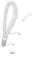
- the carrying loop 14 shown in more detail has a loop portion 26 and a threaded portion 28.
- the threaded portion 28 is prepared for screwing into a corresponding mating thread in the tower segment 16.
- a tower segment 16 can thus as in the FIG. 1 indicated for lifting be prepared with a lifting device 1.
- the carrying loops 14 are screwed into the tower segment 16 and project upwards.
- To carry the carrying loops 14 are connected to the corresponding fastening means 2 and can be lifted, as in FIG. 3 is indicated. After settling, however, the fastener is not released from the support loop 14 but the fastener 2 is rotated by the triggering device 4, whereby the carrying loops 14 are rotated and thereby can be released from the tower segment 16.
- the tower segment 16 thus remains at its intended installation site, wherein the carrying loops 14 are already removed and the next tower segment can be placed on the last erected tower segment.
- FIG. 5 shows a centering pin 50 and a centering sleeve 52.
- the centering pin 50 has a mounting portion 54 and a guide portion 56.
- the attachment portion 54 is formed substantially as a threaded pin and carries the guide portion 56 which is tapered and tapers from a side facing away from the attachment portion 54.
- the guide portion 56 is designed in approximately conical shape.
- the centering sleeve 52 has an opening 58, through which the guide section 56 of the centering pin 50 can be inserted into a cavity in the centering sleeve 52.
- an outer contour 60 can be seen, which basically indicates the shape of an inner contour of the cavity.
- the centering sleeve 52 is intended to be concreted in a tower segment made of concrete during its manufacture, so that substantially the opening 58 and also the positioning plate 62 is still accessible at a lower abutment surface of the tower segment.
- the positioning plate 62 has two positioning recesses 64. Before concreting the centering sleeve 52 is placed with the positioning plate 62 facing down on a flat surface on which a mold for casting the tower segment is placed. On each of these flat surfaces or plates, two centering lugs 52 are provided for each centering sleeve, each of which engages in the positioning recesses 64 and thus precisely positions the centering sleeve 52.
- the positioning plate 62 achieves the most accurate possible vertical alignment of the centering sleeve 52, in particular with respect to the outer contour 60, which receives the cavity.
- a holding plate 66 is provided, which can also be referred to as a headband and in particular holds the centering sleeve in the casting of concrete in position.
- the circumferential rounded outer webs 68 support a good grip in the concrete.
- FIG. 6 shows the centering pin 50 in a partially inserted into the centering sleeve 52 state, for illustration.
- the centering mandrel 50 namely the guide portion 56 only when putting two tower segments in the centering rierhülse 52 introduced, which is already embedded in one of the two tower segment.
- the work platform apparatus 100 of the FIG. 7 includes a work basket 102 and a lift 104 having a pulley 106.
- the working platform device 100 is fastened to a tower ladder 108, which is provided with ladder rungs 110 and a safety rail 112.
- the lifting means 104 has a load arm 114, which is secured against displacement by means of a fastening section 116 on the safety rail 112.
- On the load arm 14 of the pulley 106 is attached and also it is attached to the work basket 102, which can thus be pulled by means of the pulley in a higher position.
- the work basket 102 is also fastened to the tower ladder 108 so as to be shift-proof in a working position.
- the pulley 106 and the lifting means 104 in total should keep the work basket 102 only when putting the same in a higher position and lift.
- the work basket 102 thus also substantially only in the unloaded condition, ie keep and raise staff without work.
- the work basket 102 has a railing 118 with various attachment points for attaching the pulley 106 for lifting the work basket 102.
- the railing 118 is otherwise intended to prevent a person from falling out of the work basket 102. This is supported by some protective walls 120.
- the work basket 102 also has a hinged platform 122 which serves as the bottom of the work basket 102.
- the platform 122 is shown in a folded-to-side position in which a person may exit the work basket 102 downward.
- the folded-away platform 122 releases a corresponding bottom opening 124.
- the folding direction of the platform is indicated by the arrow 126.
- a pivotable tool box 128 is provided, which can be pivoted into or out of the work basket 102 as needed.
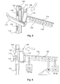
- FIG. 8 illustrates the attachment of the load arm 114 to the safety rail 112.
- the load arm 114 is thereby fastened by means of the fastening portion 116 on the safety rail 112.
- the fastening portion 116 has a fastening hook 130, which is intended to engage in an elongated opening 132, which can also be referred to as a slot and is arranged on the rear side of the safety rail 112.
- To attach the load arm 114 is slightly inclined with its mounting portion 116 and the mounting hook 130 in the safety rail 112, which is designed as a so-called C-profile, inserted and pushed slightly down to its mounted position.
- a locking pin 134 is provided, which engages in the fixed position in the same slot 132 as the fastening hook 130.
- the fully inserted position is in the FIG. 9 illustrated in a side view.
- FIG. 9 also illustrates that in the load arm 114 a plurality of mounting holes 138 are provided which provide different attachment positions for the pulley 106 of the lifting means 104. Different mounting holes 138 can accommodate different weights. In addition, by a skillful choice of the mounting hole 138 a favorable pulling direction when lifting the working basket 102 can be selected.
- FIG. 10 basically shows a side view of the situation of FIG. 7 , It can also be seen here that an actuating portion 140 is attached to a cable 142 of the pulley 106, wherein the cable 142 extends from a position above the work basket 102 through the work basket 102 to a position below the working basket 102. Accordingly, the work basket 102 can be pulled from a position lying below this working basket 102 to a higher position and lifted therewith. The work basket 102 is guided here by lateral guide cheeks.
- the lifting means 104 may provide corresponding secured hooks 144, which may also be generally referred to as snap hooks. Such a secured hook 144 is in the FIG.
- FIGS. 8 . 10 and 11 also in the FIG. 11 exemplified in an enlargement.
- this conductor holder 146 also leads to a distance between the tower conductor 108 and the relevant tower wall.
- FIG. 11 shows a situation similar to the one in FIG. 10 illustrated, with the pulley 106 is secured with its secure hook 144 at other positions of the working basket 102. Accordingly, no attachment to the railing 118 according to FIG. 10 but an attachment to a pivot axis 148 to pivot the platform 122 and to further support struts 150 of the work basket 102.
- the use of the pivot axis 148 and the support struts 150 to stop the secured hook 144 provides the ability to closer the work basket 102 Pull the load arm 114 up. This is particularly important when the work basket 102 is to be lifted particularly high in the tower and in particular the topmost straight tower segment to be processed.
- FIG. 11 shows the work basket 102 in a partially sectioned view.
- the pulley 106 is in accordance with the situation of FIG. 11 arranged in the work basket 102 and thus recognizable only by the cut representation.
- FIG. 12 shows the work basket 102 from a rear view, namely basically from the perspective of the tower wall to which the tower ladder 108 is attached.
- FIG. 12 thus shows a view of a basket back 152, which has a number of fasteners.
- the work basket is fastened by means of six connecting means 154 on the rear side 152 of the basket.
- Each connecting means 154 in this case comprises a locking slide 156, with which the connection between the working basket 102 and the rear of the basket 152 is made.
- the arrow 158 illustrates a movement for locking and the arrow 160 a movement for unlocking.
- three support brackets 162 are provided which position the work basket by resting on a respective ladder rung 110 in height.
- a support bracket 162 is shown in a side view.
- the support bracket has a support lever 164 in the FIG. 13 is shown in two positions, namely in a horizontal rest position and an oblique, evasive position.
- the arrow 166 indicates an evasive movement in the evaded position. If the work basket is pulled upward and the support bracket 162 passes a ladder rung 110, the ladder rung 110 will push the support lever 164 into the deflection movement 160 as a result of this upward movement of the work basket 102 and thus of the support bracket 162.
- a pivoting back of the support lever 164 by a correspondingly provided blocking device must be prevented.
- a blocking device is present, but is not illustrated in the figures.
- FIG. 14 In perspective, a first tower segment 200 placed on a foundation is shown, around which a heating device with an outer sub-covering device 202 is shown.
- This outer Operaabdeckvorraum 202 encloses the thus unrecognizable impact area between the tower segment 200 and the foundation 204.
- this outer Operaabdeckvorraum 202 creates a protected space around the tower segment 200 around, which is readily accessible in height and width for adults. To illustrate schematically persons are indicated.
- the outer Operaabdeckvoriques 202 is attached to an upper, circumferential rail 206 on the tower segment 200 and seals substantially against the first tower segment. Such a seal should essentially prevent heat from escaping through convection. Furthermore, a scaffold is disposed below the outer part covering device 202, which is also connected to this circumferential upper rail and substantially determines the outer shape of the outer part covering device 202.
- FIG. 15 shows a portion of a support frame 208 of a still to be completed inner Operaabdeckvoriques.
- the inner support frame 208 has a circumferential rail, namely inner circulation rail 210.
- a person is outlined to illustrate the size of the framework 208 and thus the interior sub-masking device to be provided.
- the support frame 208 which is provided substantially for clamping a tarpaulin, for holding the support frame 208 connected thereto.
- Embodiment 2 Lifting device according to embodiment 1, prepared to loosen the connection between the lifting device and the first tower segment without residue so that a second tower segment can be arranged as intended on the tower segment.
- Embodiment 3 Lifting device according to embodiment 1 or 2, wherein the triggering device is prepared to detach, in particular unscrew a connecting element, in particular an eyelet or steel cable loop screwed into the first tower segment, out of the tower segment.
- a connecting element in particular an eyelet or steel cable loop screwed into the first tower segment, out of the tower segment.
- Embodiment 4 Lifting device according to Embodiment 3, characterized in that each fastening means is prepared to be connected respectively to the steel loop and one of the steel loops, and wherein each fastening means is provided with one of the detachment devices, around the steel loop connected to the respective fastening means to screw the first tower segment.
- Embodiment 5 Lifting device according to one of the preceding embodiments, characterized in that at least 2 fastening means are provided and / or that the or each fastening element is prepared to be releasably connected to a steel cable loop, in particular that each fastening element is a transverse bolt section or has a hook portion for insertion or hooking in one of the steel cable loops for lifting the first tower segment.
- Embodiment 6 Lifting device according to one of the preceding embodiments, characterized in that the or each triggering device comprises an electric motor to carry out the release of the connection between the carrying device and the first tower segment.
- Embodiment 9 Zentrierdorncru with a first and a second centering mandrel according to embodiment 7 or 8, wherein the first centering mandrel has a shorter guide portion than the second centering mandrel, in particular by 20% - 70% shorter, preferably by 40% - 60% shorter, the Fastening portions of both centering mandrels preferably have the same size.
- Embodiment 12 Centering set comprising at least one centering mandrel according to embodiment 7 or 8 and a centering sleeve adapted to the centering mandrel according to embodiment 10 or 11.
- Embodiment 13 Tower segment of a concrete tower with at least one centering mandrel sleeve concreted therein according to embodiment 10 or 11.
- Embodiment 15 A work platform device according to Embodiment 14, characterized in that the work basket has a bottom portion and the bottom portion can be opened so that a bottom opening is created by an adult person can leave the work basket down.
- Embodiment 16 A working platform device according to embodiment 15, characterized in that the bottom opening is formed so that the person when leaving the work basket through the bottom opening, when the work basket is attached to the tower ladder, consistently secured with a safety harness via a safety slide on the safety rail can, in particular, that the person can lead the safety slide when leaving the work basket in the rail.
- Embodiment 18 Working platform device according to embodiment 17, characterized in that the lifting means comprises a pulley block and / or a deflecting means for deflecting a carrying cable, wherein the pulley or the deflecting element is prepared for attachment to the tower ladder or safety rail.
- Embodiment 20 Method according to embodiment 19, wherein the further tower segment or another tower segment is lifted and set down with a lifting device according to one of the embodiments 1 to 6.
- Embodiment 22 Method according to embodiment 21, characterized in that a lifting device according to one of embodiments 1 to 6 is used for lifting and lowering a tower segment.
Priority Applications (3)
| Application Number | Priority Date | Filing Date | Title |
|---|---|---|---|
| RS20160924A RS55347B1 (sr) | 2011-01-26 | 2012-01-18 | Uređaj za zagrevanje |
| SI201230805A SI2805909T1 (sl) | 2011-01-26 | 2012-01-18 | Grelna naprava |
| HRP20161445TT HRP20161445T1 (hr) | 2011-01-26 | 2016-11-02 | Uređaj za zagrijavanje |
Applications Claiming Priority (2)
| Application Number | Priority Date | Filing Date | Title |
|---|---|---|---|
| DE102011003164A DE102011003164A1 (de) | 2011-01-26 | 2011-01-26 | Verfahren und Vorrichtung zum Errichten eines Turms einer Windenergieanlage |
| EP12700685.6A EP2556008B1 (fr) | 2011-01-26 | 2012-01-18 | Dispositif et procédé pour ériger un mât d'une éolienne |
Related Parent Applications (2)
| Application Number | Title | Priority Date | Filing Date |
|---|---|---|---|
| EP12700685.6A Division EP2556008B1 (fr) | 2011-01-26 | 2012-01-18 | Dispositif et procédé pour ériger un mât d'une éolienne |
| EP12700685.6A Division-Into EP2556008B1 (fr) | 2011-01-26 | 2012-01-18 | Dispositif et procédé pour ériger un mât d'une éolienne |
Publications (2)
| Publication Number | Publication Date |
|---|---|
| EP2805909A1 true EP2805909A1 (fr) | 2014-11-26 |
| EP2805909B1 EP2805909B1 (fr) | 2016-10-12 |
Family
ID=45509505
Family Applications (4)
| Application Number | Title | Priority Date | Filing Date |
|---|---|---|---|
| EP14180218.1A Active EP2805909B1 (fr) | 2011-01-26 | 2012-01-18 | Dispositif de chauffage |
| EP14180212.4A Active EP2803616B1 (fr) | 2011-01-26 | 2012-01-18 | Dispositif de plate-forme de travail pour travailler à hauteur variable et méthode correspondante |
| EP14180214.0A Active EP2803617B1 (fr) | 2011-01-26 | 2012-01-18 | Procédé de construction d'une tour d'un générateur d'énergie éolienne |
| EP12700685.6A Active EP2556008B1 (fr) | 2011-01-26 | 2012-01-18 | Dispositif et procédé pour ériger un mât d'une éolienne |
Family Applications After (3)
| Application Number | Title | Priority Date | Filing Date |
|---|---|---|---|
| EP14180212.4A Active EP2803616B1 (fr) | 2011-01-26 | 2012-01-18 | Dispositif de plate-forme de travail pour travailler à hauteur variable et méthode correspondante |
| EP14180214.0A Active EP2803617B1 (fr) | 2011-01-26 | 2012-01-18 | Procédé de construction d'une tour d'un générateur d'énergie éolienne |
| EP12700685.6A Active EP2556008B1 (fr) | 2011-01-26 | 2012-01-18 | Dispositif et procédé pour ériger un mât d'une éolienne |
Country Status (25)
| Country | Link |
|---|---|
| US (1) | US9534416B2 (fr) |
| EP (4) | EP2805909B1 (fr) |
| JP (3) | JP5860902B2 (fr) |
| KR (3) | KR101665169B1 (fr) |
| CN (3) | CN103476696B (fr) |
| AR (1) | AR085029A1 (fr) |
| AU (1) | AU2012210698B2 (fr) |
| BR (1) | BR112013018604A2 (fr) |
| CA (1) | CA2823982C (fr) |
| CL (1) | CL2013002121A1 (fr) |
| CY (2) | CY1116401T1 (fr) |
| DE (1) | DE102011003164A1 (fr) |
| DK (4) | DK2556008T3 (fr) |
| ES (3) | ES2541637T3 (fr) |
| HR (2) | HRP20150718T1 (fr) |
| HU (2) | HUE030304T2 (fr) |
| LT (1) | LT2805909T (fr) |
| MX (1) | MX336620B (fr) |
| PL (2) | PL2805909T3 (fr) |
| PT (3) | PT2805909T (fr) |
| RS (2) | RS54062B1 (fr) |
| SI (2) | SI2805909T1 (fr) |
| TW (1) | TWI480453B (fr) |
| WO (1) | WO2012101023A2 (fr) |
| ZA (1) | ZA201304951B (fr) |
Families Citing this family (41)
| Publication number | Priority date | Publication date | Assignee | Title |
|---|---|---|---|---|
| CN104797766B (zh) * | 2012-11-08 | 2017-03-15 | 贝斯特罗株式会社 | 集合型烟囱拆除用脚手架装置及使用了该装置的集合型烟囱的拆除方法 |
| DE102012221453A1 (de) * | 2012-11-23 | 2014-05-28 | Wobben Properties Gmbh | Greifeinrichtung zum Handhaben von Bewehrungskörben für Turmsegmente einer Windenergieanlage |
| DK2824057T3 (en) * | 2013-07-11 | 2017-09-11 | Siemens Ag | Lifting of a tower segment |
| PL3572366T3 (pl) * | 2013-07-17 | 2022-03-21 | Alimak Group Management Ab | System windowy |
| CN103939298B (zh) * | 2014-04-01 | 2016-04-13 | 北京金风科创风电设备有限公司 | 用于混凝土塔架拼装的结构 |
| CN104213714B (zh) * | 2014-08-27 | 2016-03-09 | 中国建筑第二工程局有限公司 | 一种超大型屋架的提升吊点加固结构及吊装施工方法 |
| AU2015330437A1 (en) * | 2014-10-06 | 2017-04-27 | Vestas Wind Systems A/S | Hinged tower segments and transport method |
| CN104631839B (zh) * | 2015-01-29 | 2016-08-24 | 浙江勤业建工集团有限公司 | 超高超重大跨度空中连廊整体提升施工方法 |
| CN104803308B (zh) * | 2015-04-28 | 2017-01-18 | 中国水利水电第八工程局有限公司 | 用于钢管加劲环拼装的吊装装置 |
| CN105119190A (zh) * | 2015-08-27 | 2015-12-02 | 国家电网公司 | 一种自锁式瓷片式绝缘子吊装架 |
| CN105119189A (zh) * | 2015-08-27 | 2015-12-02 | 国家电网公司 | 一种超长瓷片式绝缘子串吊装架 |
| WO2017039975A1 (fr) | 2015-08-31 | 2017-03-09 | Siemens Energy, Inc. | Système et procédé d'installation d'un tendon de serrage dans une tour éolienne |
| DE102016200160A1 (de) * | 2016-01-08 | 2017-07-13 | Wobben Properties Gmbh | Hebevorrichtung zum Heben einer Komponente einer Windenergieanlage und Verfahren zum Montieren von Komponenten einer Windenergieanlage |
| GB2551481A (en) * | 2016-06-08 | 2017-12-27 | John Reed Patrick | A sheeting system |
| CN106337785B (zh) * | 2016-09-29 | 2019-01-25 | 中车株洲电力机车研究所有限公司 | 风力发电机组风轮内葫芦辅助拆装工具及方法 |
| WO2018086837A1 (fr) | 2016-11-11 | 2018-05-17 | Siemens Aktiengesellschaft | Assemblage de transport |
| US10704535B2 (en) | 2016-11-23 | 2020-07-07 | Mhi Vestas Offshore Wind A/S | Method and assembly for aligning wind turbine structural parts |
| CN106640558B (zh) * | 2016-12-30 | 2019-04-12 | 北京金风科创风电设备有限公司 | 风力涡轮机的变桨轴承、叶片、叶轮及连接方法 |
| CN106903014A (zh) * | 2017-02-28 | 2017-06-30 | 李金平 | 一种喷涂行业用定心转盘 |
| CN106744252B (zh) * | 2017-03-27 | 2018-09-21 | 江苏中车电机有限公司 | 用于mw级直驱永磁风力发电机转子吊运工装及使用方法 |
| CN107152021B (zh) * | 2017-06-06 | 2023-03-28 | 中国石油天然气集团公司 | 一种u形管桩护甲安装工具 |
| EP3450752B1 (fr) | 2017-09-04 | 2020-06-17 | Siemens Gamesa Renewable Energy A/S | Éolienne ayant un agencement d'accès pour une nacelle |
| CN115783143B (zh) * | 2017-11-22 | 2023-09-08 | 自然资源部第二海洋研究所 | 船用机械臂止荡设备 |
| CN109058052B (zh) * | 2018-08-29 | 2020-08-21 | 江苏仕沃精密机械科技有限公司 | 新能源风力发电设备的集成式固定安装架 |
| CN109809287B (zh) * | 2019-03-18 | 2020-05-12 | 哈尔滨电机厂有限责任公司 | 一种用于周向装配的对称起吊装置的使用方法 |
| CN110565934A (zh) * | 2019-07-26 | 2019-12-13 | 江苏兴厦建设工程集团有限公司 | 一种建筑外墙悬吊式人货电梯施工平台及其安装方法 |
| DE102019122021A1 (de) * | 2019-08-15 | 2021-02-18 | Wobben Properties Gmbh | Montagetraverse und Verfahren zum Einziehen von kabelförmigen Elementen, insbesondere von Spanngliedern, entlang eines Turms einer Windenergieanlage |
| JP6798721B1 (ja) * | 2019-09-30 | 2020-12-09 | 村田油圧機械株式会社 | 連絡ブリッジ用の水平回動アクチュエータ |
| JP6798720B1 (ja) * | 2019-09-30 | 2020-12-09 | 村田油圧機械株式会社 | 連絡ブリッジ用の伸縮アクチュエータ |
| JP6882795B2 (ja) * | 2019-09-30 | 2021-06-02 | 村田油圧機械株式会社 | 連絡ブリッジ |
| CN111039152B (zh) * | 2019-12-31 | 2021-01-26 | 烟台腾泰环保建材有限公司 | 一种混凝土预制构件 |
| CN111980865B (zh) * | 2020-07-29 | 2021-11-12 | 上海市机电设计研究院有限公司 | 减小预制混凝土筒片错动的筒节吊装方法 |
| CN111997432B (zh) * | 2020-07-29 | 2021-12-14 | 上海市机电设计研究院有限公司 | 预制混凝土塔筒的施工平台提升装置及方法 |
| CN113023540B (zh) * | 2021-03-15 | 2022-03-01 | 合肥中科离子医学技术装备有限公司 | 一种用于回旋加速器整机的吊装运输一体式装置 |
| CN113090037A (zh) * | 2021-04-01 | 2021-07-09 | 浙江明康工程咨询有限公司 | 一种卸料平台的预警方法及系统 |
| CN113503047A (zh) * | 2021-07-31 | 2021-10-15 | 中冶(上海)钢结构科技有限公司 | 钢结构提升过程中牵引调整高空位置偏移的方法 |
| CN113756647B (zh) * | 2021-09-04 | 2022-11-08 | 中铁十五局集团有限公司 | 一种线路铁塔分段结构的施工方法及其装置 |
| CN113944313B (zh) * | 2021-11-03 | 2023-04-11 | 上海建工五建集团有限公司 | 悬挑型钢顶撑限位装置、悬挑钢平台及其施工方法 |
| CN114108996B (zh) * | 2021-11-26 | 2023-06-06 | 中煤西安设计工程有限责任公司 | 一种无楼板砖砌填充墙的施工装置及方法 |
| CN115285854B (zh) * | 2022-09-28 | 2022-12-02 | 中国能源建设集团山西电力建设有限公司 | 大型圆柱形罐体的低空拼装分节抬升的装配方法 |
| CN117703164B (zh) * | 2024-02-05 | 2024-04-09 | 辽宁省送变电工程有限公司 | 高低铁塔塔腿段组立自动提升装置 |
Citations (5)
| Publication number | Priority date | Publication date | Assignee | Title |
|---|---|---|---|---|
| US3074564A (en) | 1961-03-01 | 1963-01-22 | Chicago Bridge & Iron Co | Mast extension jib |
| DE8424193U1 (de) * | 1984-08-16 | 1985-12-12 | Ernst Peiniger GmbH Unternehmen für Bautenschutz, 4300 Essen | Arbeitsplatzverschlag |
| DE202010000868U1 (de) | 2009-07-20 | 2010-12-02 | Wader-Wittis Gmbh | Vorrichtung zum Transport und zur Montage von Windkraftanlagen |
| DE102009023538A1 (de) | 2009-05-30 | 2010-12-09 | Kai Berkenbrink | Turm einer Windkraftanlage, Windkraftanlage sowie Verfahren zum Anheben von Komponenten einer Windkraftanlage |
| WO2010147459A2 (fr) * | 2009-06-19 | 2010-12-23 | Xemc Darwind B.V. | Procédé de finition d'une section de tour d'une turbine éolienne, section de tour finie d'une turbine éolienne et procédé pour transporter une section de tour d'une turbine éolienne |
Family Cites Families (47)
| Publication number | Priority date | Publication date | Assignee | Title |
|---|---|---|---|---|
| DE1251803B (de) * | 1963-12-05 | 1967-10-12 | Siemens Aktiengesellschaft, Berlin und München München | Verfah ren und Einrichtung zum Regenerieren von phasenmodulierten Impulsfolgen |
| CH508507A (de) * | 1969-05-28 | 1971-06-15 | Von Roll Ag | Zahnstange für eine Fahrschiene für Hängebahnen |
| JPS5830882Y2 (ja) * | 1978-06-21 | 1983-07-08 | 住友金属工業株式会社 | 大型コンクリ−ト構造体用吊筋 |
| SU958296A1 (ru) | 1980-06-12 | 1982-09-15 | Республиканское Проектно-Технологическое Производственное Объединение "Росоргтехстрой" | Захват-кантователь дл изделий с цапфами |
| EP0688922B1 (fr) * | 1994-06-23 | 1998-04-22 | HALFEN GmbH & CO. Kommanditgesellschaft | Ancrage de manutention notamment pour éléments en béton préfabriqués et élément de manutention vissé dans l'ancrage |
| TW253924B (en) | 1994-09-14 | 1995-08-11 | Nippon Kotetsu Kokusai Kk | Elevatable work facility |
| JPH08303441A (ja) * | 1995-05-01 | 1996-11-19 | Aioi Seiki Kk | ガイド兼ロック機構付きコネクタ装置 |
| CA2362179A1 (fr) * | 1998-02-04 | 1999-08-12 | Stephen L. Heston | Dispositif de palettisation |
| DE19857744B4 (de) * | 1998-12-15 | 2007-05-16 | Schuler Pressen Gmbh & Co | Presse mit Stempelverstellung, insbesondere zur Massivumformung |
| JP2000283019A (ja) * | 1999-03-31 | 2000-10-10 | Pc Bridge Co Ltd | コンクリート製風車支持タワー及びその構築方法 |
| DE10025074B4 (de) | 2000-05-20 | 2006-11-09 | Hailo-Werk Rudolf Loh Gmbh & Co. Kg | Einrichtung zum Befördern von Personen |
| US6782667B2 (en) | 2000-12-05 | 2004-08-31 | Z-Tek, Llc | Tilt-up and telescopic support tower for large structures |
| DE10104351A1 (de) * | 2001-02-01 | 2002-08-22 | Ingenieurgesellschaft Foerder | Aufzug mit auf der Aufzugskabine mitfahrender Antriebseinheit und Steuereinheit |
| US6625940B2 (en) * | 2001-02-02 | 2003-09-30 | Wallace D. Sanger | Concrete building module with module lifting means and method |
| DE10160022A1 (de) * | 2001-12-06 | 2003-06-18 | Gen Electric | Verfahren zum Herstellen eines Turms einer Windkraftanlage, mit diesem Verfahren hergestellter Turm und Bauelemente zur Herstellung eines Turms |
| DE10163538B4 (de) * | 2001-12-21 | 2004-09-30 | Norbert Plambeck | Vorrichtung und Verfahren zum Transport und zur Errichtung von Offshore-Windenergieanlagen |
| GB2394498B (en) * | 2002-10-23 | 2006-08-09 | Engineering Business Ltd | Mounting of offshore structures |
| JP2004156478A (ja) * | 2002-11-05 | 2004-06-03 | Kashiwabara Painting Works Co Ltd | 独立型塔体構造物の作業用足場装置及び作業用足場設置工法 |
| CN100445552C (zh) * | 2003-12-30 | 2008-12-24 | Pp能源有限责任公司 | 用于抵达位于地面上方的结构的设备 |
| GB0500619D0 (en) | 2005-01-13 | 2005-02-23 | Severfield Rowen Plc | Improvements relating to construction |
| CN101614083B (zh) * | 2005-01-19 | 2014-09-24 | Iti苏格兰有限公司 | 夹具、自移式爬升装置和联接夹具与管形件的方法 |
| US20060213145A1 (en) * | 2005-03-22 | 2006-09-28 | Haller Mark E | Lattice-skin hybrid tower |
| JP2007046292A (ja) * | 2005-08-09 | 2007-02-22 | Oriental Construction Co Ltd | タワー構築用ブロック |
| JP4701047B2 (ja) * | 2005-09-07 | 2011-06-15 | 株式会社竹中工務店 | 風力発電タワーの構築方法 |
| TWM296876U (en) | 2006-03-07 | 2006-09-01 | Runhorn Pretech Eng Co Ltd | Wall structure preset hanging point |
| CN101484698A (zh) * | 2006-06-29 | 2009-07-15 | 维斯塔斯风力系统有限公司 | 用于风轮机的塔体构造 |
| DE602007011264D1 (de) * | 2006-06-30 | 2011-01-27 | Vestas Wind Sys As | Hubeinrichtung zur handhabung einer windturbinenkomponente und verfahren zur handhabung einer windturbinenkomponente |
| BRPI0719789A8 (pt) * | 2006-10-02 | 2017-08-15 | Wind Tower Systems Llc | Sistema de levantamento e aparelho para construir e vedar torres de turbina eólica. |
| KR20090011746A (ko) * | 2007-07-27 | 2009-02-02 | 주식회사 피엔에이치 | 자동 개방형 샤클 조립체의 안전장치 |
| AU2008221636A1 (en) * | 2007-10-11 | 2009-04-30 | General Electric Company | Wind tower and method of assembling the same |
| WO2009101697A1 (fr) * | 2008-02-15 | 2009-08-20 | Sakuraigiken Co., Ltd. | Procédé et appareil pour la maintenance d'une pale d'éolienne d'un équipement éolien |
| US20090223163A1 (en) | 2008-03-10 | 2009-09-10 | Shu Ching Quek | Wind Turbine Tower Including An Induction Brazed Joint And A Method Of Fabricating The Wind Turbine Tower |
| JP5069171B2 (ja) * | 2008-05-22 | 2012-11-07 | 鹿島建設株式会社 | 洋上風力発電の基礎と上部工の接合部構造および上部工の据付方法 |
| TW201016961A (en) | 2008-10-16 | 2010-05-01 | Mitsubishi Heavy Ind Ltd | Wind-powered electric generator |
| ES2448769T3 (es) * | 2008-11-03 | 2014-03-17 | Siemens Aktiengesellschaft | Cimentación, particularmente para una turbina eólica, y turbina eólica |
| ES2386519T3 (es) * | 2008-11-27 | 2012-08-22 | Vestas Wind Systems A/S | Torre para una turbina eólica y método para montar la torre |
| CN101481069B (zh) * | 2008-12-10 | 2012-09-05 | 三一电气有限责任公司 | 一种攀爬系统和攀爬起吊系统 |
| SE534035C2 (sv) * | 2009-04-08 | 2011-04-12 | Ncc Construction Sverige Ab | Förfarande för byggande av vindkraftverk |
| DE102009061027A1 (de) * | 2009-04-19 | 2010-10-28 | Timber Tower Gmbh | Turm für eine Windkraftanlage |
| US8281546B2 (en) * | 2009-05-05 | 2012-10-09 | Thompson Bradley D | Slip formed concrete wind turbine tower |
| BR112012000808A2 (pt) | 2009-07-13 | 2016-02-23 | Vsl Int Ag | conjunto de torre telescópica e método |
| DK2456710T3 (da) * | 2009-07-24 | 2013-10-14 | Siemens Ag | Løftebeslag |
| US8596700B2 (en) * | 2009-08-14 | 2013-12-03 | Mjt Holdings, Llc | Tower erection lift kit tools |
| DE102009051425A1 (de) | 2009-10-30 | 2011-05-05 | Voith Patent Gmbh | Strömungskraftwerk und Verfahren für dessen Erstellung |
| US8544924B2 (en) * | 2009-11-06 | 2013-10-01 | Engineered Lifting Technologies, Inc. | Lifting assembly |
| US8434799B2 (en) * | 2010-06-03 | 2013-05-07 | Robert J. Reger | Synthetic fiber sling and roller system for carrying and positioning a load |
| DK2402278T3 (da) * | 2010-06-29 | 2012-12-10 | Siemens Ag | Indretning til løftning af et tårnvægafsnit af en vindturbine og fremgangsmåde til løftning af et tårnvægafsnit af en vindturbine |
-
2011
- 2011-01-26 DE DE102011003164A patent/DE102011003164A1/de not_active Withdrawn
-
2012
- 2012-01-18 HU HUE14180218A patent/HUE030304T2/en unknown
- 2012-01-18 LT LTEP14180218.1T patent/LT2805909T/lt unknown
- 2012-01-18 RS RS20150408A patent/RS54062B1/en unknown
- 2012-01-18 ES ES12700685.6T patent/ES2541637T3/es active Active
- 2012-01-18 CN CN201280006757.0A patent/CN103476696B/zh active Active
- 2012-01-18 DK DK12700685.6T patent/DK2556008T3/en active
- 2012-01-18 SI SI201230805A patent/SI2805909T1/sl unknown
- 2012-01-18 EP EP14180218.1A patent/EP2805909B1/fr active Active
- 2012-01-18 CN CN201510309176.XA patent/CN105035939B/zh not_active Expired - Fee Related
- 2012-01-18 PL PL14180218T patent/PL2805909T3/pl unknown
- 2012-01-18 MX MX2013008532A patent/MX336620B/es unknown
- 2012-01-18 BR BR112013018604-6A patent/BR112013018604A2/pt not_active Application Discontinuation
- 2012-01-18 PL PL12700685T patent/PL2556008T3/pl unknown
- 2012-01-18 AU AU2012210698A patent/AU2012210698B2/en not_active Ceased
- 2012-01-18 ES ES14180218.1T patent/ES2611830T3/es active Active
- 2012-01-18 KR KR1020137022160A patent/KR101665169B1/ko active IP Right Grant
- 2012-01-18 EP EP14180212.4A patent/EP2803616B1/fr active Active
- 2012-01-18 HU HUE12700685A patent/HUE026787T2/en unknown
- 2012-01-18 EP EP14180214.0A patent/EP2803617B1/fr active Active
- 2012-01-18 US US13/981,713 patent/US9534416B2/en active Active
- 2012-01-18 DK DK14180214.0T patent/DK2803617T3/en active
- 2012-01-18 JP JP2013550827A patent/JP5860902B2/ja active Active
- 2012-01-18 EP EP12700685.6A patent/EP2556008B1/fr active Active
- 2012-01-18 KR KR1020157019627A patent/KR20150090266A/ko not_active Application Discontinuation
- 2012-01-18 SI SI201230211T patent/SI2556008T1/sl unknown
- 2012-01-18 DK DK14180218.1T patent/DK2805909T3/en active
- 2012-01-18 PT PT141802181T patent/PT2805909T/pt unknown
- 2012-01-18 PT PT141802140T patent/PT2803617T/pt unknown
- 2012-01-18 PT PT127006856T patent/PT2556008E/pt unknown
- 2012-01-18 KR KR1020157019628A patent/KR20150090267A/ko not_active Application Discontinuation
- 2012-01-18 RS RS20160924A patent/RS55347B1/sr unknown
- 2012-01-18 ES ES14180214.0T patent/ES2658437T3/es active Active
- 2012-01-18 DK DK14180212.4T patent/DK2803616T3/da active
- 2012-01-18 WO PCT/EP2012/050729 patent/WO2012101023A2/fr active Application Filing
- 2012-01-18 CA CA2823982A patent/CA2823982C/fr not_active Expired - Fee Related
- 2012-01-18 CN CN201510309673.XA patent/CN105020228B/zh not_active Expired - Fee Related
- 2012-01-19 TW TW101102283A patent/TWI480453B/zh not_active IP Right Cessation
- 2012-01-25 AR ARP120100242A patent/AR085029A1/es active IP Right Grant
-
2013
- 2013-07-03 ZA ZA2013/04951A patent/ZA201304951B/en unknown
- 2013-07-24 CL CL2013002121A patent/CL2013002121A1/es unknown
-
2014
- 2014-10-31 JP JP2014223332A patent/JP6282572B2/ja active Active
- 2014-10-31 JP JP2014223324A patent/JP6038098B2/ja active Active
-
2015
- 2015-06-12 CY CY20151100516T patent/CY1116401T1/el unknown
- 2015-07-02 HR HRP20150718TT patent/HRP20150718T1/hr unknown
-
2016
- 2016-11-02 HR HRP20161445TT patent/HRP20161445T1/hr unknown
- 2016-12-09 CY CY20161101275T patent/CY1118427T1/el unknown
Patent Citations (5)
| Publication number | Priority date | Publication date | Assignee | Title |
|---|---|---|---|---|
| US3074564A (en) | 1961-03-01 | 1963-01-22 | Chicago Bridge & Iron Co | Mast extension jib |
| DE8424193U1 (de) * | 1984-08-16 | 1985-12-12 | Ernst Peiniger GmbH Unternehmen für Bautenschutz, 4300 Essen | Arbeitsplatzverschlag |
| DE102009023538A1 (de) | 2009-05-30 | 2010-12-09 | Kai Berkenbrink | Turm einer Windkraftanlage, Windkraftanlage sowie Verfahren zum Anheben von Komponenten einer Windkraftanlage |
| WO2010147459A2 (fr) * | 2009-06-19 | 2010-12-23 | Xemc Darwind B.V. | Procédé de finition d'une section de tour d'une turbine éolienne, section de tour finie d'une turbine éolienne et procédé pour transporter une section de tour d'une turbine éolienne |
| DE202010000868U1 (de) | 2009-07-20 | 2010-12-02 | Wader-Wittis Gmbh | Vorrichtung zum Transport und zur Montage von Windkraftanlagen |
Also Published As
Similar Documents
| Publication | Publication Date | Title |
|---|---|---|
| EP2556008B1 (fr) | Dispositif et procédé pour ériger un mât d'une éolienne | |
| EP1929107B1 (fr) | Dispositif de protection et d'acces | |
| EP3495561B1 (fr) | Ensemble plate-forme, structure offshore, procédé d'installation d'un ensemble plate-forme | |
| DE202010003033U1 (de) | Hebezeug zur Positionierung eines Rotorblatts einer Windenergieanlage | |
| WO2006097505A1 (fr) | Plateforme de travail | |
| EP3042011B1 (fr) | Procédé de montage d'équipements d'une tour | |
| EP2906817A1 (fr) | Dispositif de sécurité pour opérateur effectuant l'entretien d'un moyeu d'une éolienne | |
| EP0034819A2 (fr) | Echafaudage mobile | |
| EP3047083B1 (fr) | Toit de protection variable | |
| EP2823860B1 (fr) | Système de sécurité pour personnes | |
| DE102010060639A1 (de) | Arbeitsbühnenanlage | |
| WO2019076786A1 (fr) | Procédé pour ériger un pylône, segment de pylône, structure d'approvisionnement ainsi que pylône | |
| DE10212305A1 (de) | Verfahren und Vorrichtung zum Errichten von Türmen aus vorgefertigten Elementen | |
| CH632083A5 (de) | Kuehlturm. | |
| DE10308239A1 (de) | Verfahren und Vorrichtung zur Errichtung einer Windenergieanlage | |
| DE202014104436U1 (de) | Sandkasten | |
| DE19653847C2 (de) | System zum Ermöglichen eines Eingriffs am Ende eines im wesentlichen horizontalen, am Schaft eines Masts befestigten Arms, insbesondere eines Hochspannungsmasts | |
| EP3560882B1 (fr) | Passage pour un ascenseur | |
| DE19934273C2 (de) | Gerüstsystem | |
| DE202017100749U1 (de) | System zum Abspulen von Spannlitzen | |
| WO2020094735A1 (fr) | Fixation d'engin de levage et engin de levage pour turbines éoliennes | |
| DE102020109162A1 (de) | Verfahren sowie Montagetisch zur Montage einer Tragstruktur für elektrische und/oder mechanische Komponenten für ein Turmsegment eines Windkraftturms | |
| NZ613000B2 (en) | Method and device for erecting a tower for a wind energy plant |
Legal Events
| Date | Code | Title | Description |
|---|---|---|---|
| PUAI | Public reference made under article 153(3) epc to a published international application that has entered the european phase |
Free format text: ORIGINAL CODE: 0009012 |
|
| 17P | Request for examination filed |
Effective date: 20140807 |
|
| AC | Divisional application: reference to earlier application |
Ref document number: 2556008 Country of ref document: EP Kind code of ref document: P |
|
| AK | Designated contracting states |
Kind code of ref document: A1 Designated state(s): AL AT BE BG CH CY CZ DE DK EE ES FI FR GB GR HR HU IE IS IT LI LT LU LV MC MK MT NL NO PL PT RO RS SE SI SK SM TR |
|
| R17P | Request for examination filed (corrected) |
Effective date: 20150526 |
|
| RBV | Designated contracting states (corrected) |
Designated state(s): AL AT BE BG CH CY CZ DE DK EE ES FI FR GB GR HR HU IE IS IT LI LT LU LV MC MK MT NL NO PL PT RO RS SE SI SK SM TR |
|
| RIC1 | Information provided on ipc code assigned before grant |
Ipc: B66C 1/10 20060101ALI20151026BHEP Ipc: B66B 19/00 20060101ALI20151026BHEP Ipc: F02C 6/18 20060101ALI20151026BHEP Ipc: B66B 9/187 20060101ALI20151026BHEP Ipc: E04G 21/14 20060101ALI20151026BHEP Ipc: F03D 11/04 20060101AFI20151026BHEP Ipc: F03D 1/00 20060101ALI20151026BHEP |
|
| GRAP | Despatch of communication of intention to grant a patent |
Free format text: ORIGINAL CODE: EPIDOSNIGR1 |
|
| RAP1 | Party data changed (applicant data changed or rights of an application transferred) |
Owner name: WOBBEN PROPERTIES GMBH |
|
| INTG | Intention to grant announced |
Effective date: 20151221 |
|
| REG | Reference to a national code |
Ref country code: DE Ref legal event code: R079 Ref document number: 502012008548 Country of ref document: DE Free format text: PREVIOUS MAIN CLASS: B66C0001100000 Ipc: F03D0001000000 |
|
| GRAP | Despatch of communication of intention to grant a patent |
Free format text: ORIGINAL CODE: EPIDOSNIGR1 |
|
| INTG | Intention to grant announced |
Effective date: 20160525 |
|
| RIC1 | Information provided on ipc code assigned before grant |
Ipc: E04G 3/28 20060101ALI20160517BHEP Ipc: E04G 21/14 20060101ALI20160517BHEP Ipc: B66B 19/00 20060101ALI20160517BHEP Ipc: E04B 1/04 20060101ALI20160517BHEP Ipc: E04H 12/34 20060101ALI20160517BHEP Ipc: F24H 3/02 20060101ALI20160517BHEP Ipc: E04H 12/12 20060101ALI20160517BHEP Ipc: B66C 1/10 20060101ALI20160517BHEP Ipc: E04G 5/00 20060101ALI20160517BHEP Ipc: F03D 13/20 20160101ALI20160517BHEP Ipc: F16B 1/00 20060101ALI20160517BHEP Ipc: F03D 1/00 20060101AFI20160517BHEP Ipc: B66B 9/187 20060101ALI20160517BHEP Ipc: F02C 6/18 20060101ALI20160517BHEP Ipc: F16B 35/06 20060101ALI20160517BHEP |
|
| GRAS | Grant fee paid |
Free format text: ORIGINAL CODE: EPIDOSNIGR3 |
|
| GRAA | (expected) grant |
Free format text: ORIGINAL CODE: 0009210 |
|
| AC | Divisional application: reference to earlier application |
Ref document number: 2556008 Country of ref document: EP Kind code of ref document: P |
|
| AK | Designated contracting states |
Kind code of ref document: B1 Designated state(s): AL AT BE BG CH CY CZ DE DK EE ES FI FR GB GR HR HU IE IS IT LI LT LU LV MC MK MT NL NO PL PT RO RS SE SI SK SM TR |
|
| REG | Reference to a national code |
Ref country code: GB Ref legal event code: FG4D Free format text: NOT ENGLISH |
|
| REG | Reference to a national code |
Ref country code: CH Ref legal event code: NV Representative=s name: WEINMANN ZIMMERLI, CH Ref country code: CH Ref legal event code: EP |
|
| REG | Reference to a national code |
Ref country code: AT Ref legal event code: REF Ref document number: 836761 Country of ref document: AT Kind code of ref document: T Effective date: 20161015 |
|
| REG | Reference to a national code |
Ref country code: HR Ref legal event code: TUEP Ref document number: P20161445 Country of ref document: HR Ref country code: IE Ref legal event code: FG4D Free format text: LANGUAGE OF EP DOCUMENT: GERMAN |
|
| REG | Reference to a national code |
Ref country code: DE Ref legal event code: R096 Ref document number: 502012008548 Country of ref document: DE |
|
| REG | Reference to a national code |
Ref country code: HR Ref legal event code: T1PR Ref document number: P20161445 Country of ref document: HR |
|
| REG | Reference to a national code |
Ref country code: RO Ref legal event code: EPE |
|
| REG | Reference to a national code |
Ref country code: NL Ref legal event code: FP |
|
| REG | Reference to a national code |
Ref country code: PT Ref legal event code: SC4A Ref document number: 2805909 Country of ref document: PT Date of ref document: 20170112 Kind code of ref document: T Free format text: AVAILABILITY OF NATIONAL TRANSLATION Effective date: 20170103 |
|
| REG | Reference to a national code |
Ref country code: DK Ref legal event code: T3 Effective date: 20170116 |
|
| REG | Reference to a national code |
Ref country code: FR Ref legal event code: PLFP Year of fee payment: 6 |
|
| REG | Reference to a national code |
Ref country code: SE Ref legal event code: TRGR |
|
| REG | Reference to a national code |
Ref country code: EE Ref legal event code: FG4A Ref document number: E013041 Country of ref document: EE Effective date: 20161205 |
|
| REG | Reference to a national code |
Ref country code: NO Ref legal event code: T2 Effective date: 20161012 |
|
| REG | Reference to a national code |
Ref country code: HU Ref legal event code: AG4A Ref document number: E030304 Country of ref document: HU |
|
| REG | Reference to a national code |
Ref country code: ES Ref legal event code: FG2A Ref document number: 2611830 Country of ref document: ES Kind code of ref document: T3 Effective date: 20170510 |
|
| REG | Reference to a national code |
Ref country code: SK Ref legal event code: T3 Ref document number: E 23085 Country of ref document: SK |
|
| REG | Reference to a national code |
Ref country code: GR Ref legal event code: EP Ref document number: 20160403061 Country of ref document: GR Effective date: 20170410 |
|
| REG | Reference to a national code |
Ref country code: DE Ref legal event code: R097 Ref document number: 502012008548 Country of ref document: DE |
|
| PLBE | No opposition filed within time limit |
Free format text: ORIGINAL CODE: 0009261 |
|
| STAA | Information on the status of an ep patent application or granted ep patent |
Free format text: STATUS: NO OPPOSITION FILED WITHIN TIME LIMIT |
|
| PG25 | Lapsed in a contracting state [announced via postgrant information from national office to epo] |
Ref country code: SM Free format text: LAPSE BECAUSE OF FAILURE TO SUBMIT A TRANSLATION OF THE DESCRIPTION OR TO PAY THE FEE WITHIN THE PRESCRIBED TIME-LIMIT Effective date: 20161012 |
|
| 26N | No opposition filed |
Effective date: 20170713 |
|
| PG25 | Lapsed in a contracting state [announced via postgrant information from national office to epo] |
Ref country code: MC Free format text: LAPSE BECAUSE OF FAILURE TO SUBMIT A TRANSLATION OF THE DESCRIPTION OR TO PAY THE FEE WITHIN THE PRESCRIBED TIME-LIMIT Effective date: 20161012 |
|
| PG25 | Lapsed in a contracting state [announced via postgrant information from national office to epo] |
Ref country code: LU Free format text: LAPSE BECAUSE OF NON-PAYMENT OF DUE FEES Effective date: 20170118 |
|
| REG | Reference to a national code |
Ref country code: FR Ref legal event code: PLFP Year of fee payment: 7 |
|
| PG25 | Lapsed in a contracting state [announced via postgrant information from national office to epo] |
Ref country code: MT Free format text: LAPSE BECAUSE OF FAILURE TO SUBMIT A TRANSLATION OF THE DESCRIPTION OR TO PAY THE FEE WITHIN THE PRESCRIBED TIME-LIMIT Effective date: 20161012 |
|
| REG | Reference to a national code |
Ref country code: HR Ref legal event code: ODRP Ref document number: P20161445 Country of ref document: HR Payment date: 20190110 Year of fee payment: 8 |
|
| REG | Reference to a national code |
Ref country code: HR Ref legal event code: ODRP Ref document number: P20161445 Country of ref document: HR Payment date: 20200109 Year of fee payment: 9 |
|
| PGFP | Annual fee paid to national office [announced via postgrant information from national office to epo] |
Ref country code: PL Payment date: 20191209 Year of fee payment: 9 |
|
| PGFP | Annual fee paid to national office [announced via postgrant information from national office to epo] |
Ref country code: RO Payment date: 20200113 Year of fee payment: 9 Ref country code: LV Payment date: 20200124 Year of fee payment: 9 Ref country code: BG Payment date: 20200127 Year of fee payment: 9 Ref country code: EE Payment date: 20200122 Year of fee payment: 9 Ref country code: FI Payment date: 20200121 Year of fee payment: 9 Ref country code: HU Payment date: 20200108 Year of fee payment: 9 Ref country code: GR Payment date: 20200121 Year of fee payment: 9 Ref country code: NO Payment date: 20200123 Year of fee payment: 9 Ref country code: PT Payment date: 20200110 Year of fee payment: 9 Ref country code: AT Payment date: 20200121 Year of fee payment: 9 Ref country code: LT Payment date: 20200107 Year of fee payment: 9 Ref country code: ES Payment date: 20200219 Year of fee payment: 9 Ref country code: IE Payment date: 20200122 Year of fee payment: 9 Ref country code: SE Payment date: 20200127 Year of fee payment: 9 Ref country code: AL Payment date: 20191210 Year of fee payment: 9 Ref country code: IT Payment date: 20200122 Year of fee payment: 9 |
|
| PGFP | Annual fee paid to national office [announced via postgrant information from national office to epo] |
Ref country code: CZ Payment date: 20200110 Year of fee payment: 9 Ref country code: BE Payment date: 20200122 Year of fee payment: 9 Ref country code: HR Payment date: 20200109 Year of fee payment: 9 Ref country code: RS Payment date: 20200106 Year of fee payment: 9 Ref country code: CY Payment date: 20200115 Year of fee payment: 9 Ref country code: IS Payment date: 20200122 Year of fee payment: 9 Ref country code: CH Payment date: 20200127 Year of fee payment: 9 Ref country code: SI Payment date: 20200109 Year of fee payment: 9 Ref country code: SK Payment date: 20200107 Year of fee payment: 9 |
|
| PGFP | Annual fee paid to national office [announced via postgrant information from national office to epo] |
Ref country code: TR Payment date: 20200110 Year of fee payment: 9 Ref country code: MK Payment date: 20200103 Year of fee payment: 9 |
|
| REG | Reference to a national code |
Ref country code: HR Ref legal event code: PBON Ref document number: P20161445 Country of ref document: HR Effective date: 20210118 |
|
| REG | Reference to a national code |
Ref country code: FI Ref legal event code: MAE |
|
| REG | Reference to a national code |
Ref country code: EE Ref legal event code: MM4A Ref document number: E013041 Country of ref document: EE Effective date: 20210131 |
|
| REG | Reference to a national code |
Ref country code: NO Ref legal event code: MMEP |
|
| REG | Reference to a national code |
Ref country code: CH Ref legal event code: PL Ref country code: SE Ref legal event code: EUG |
|
| REG | Reference to a national code |
Ref country code: AT Ref legal event code: MM01 Ref document number: 836761 Country of ref document: AT Kind code of ref document: T Effective date: 20210118 |
|
| REG | Reference to a national code |
Ref country code: SK Ref legal event code: MM4A Ref document number: E 23085 Country of ref document: SK Effective date: 20210118 |
|
| REG | Reference to a national code |
Ref country code: BE Ref legal event code: MM Effective date: 20210131 |
|
| REG | Reference to a national code |
Ref country code: LT Ref legal event code: MM4D Effective date: 20210118 |
|
| PG25 | Lapsed in a contracting state [announced via postgrant information from national office to epo] |
Ref country code: HU Free format text: LAPSE BECAUSE OF NON-PAYMENT OF DUE FEES Effective date: 20210119 Ref country code: HR Free format text: LAPSE BECAUSE OF NON-PAYMENT OF DUE FEES Effective date: 20210118 Ref country code: EE Free format text: LAPSE BECAUSE OF NON-PAYMENT OF DUE FEES Effective date: 20210131 Ref country code: CY Free format text: LAPSE BECAUSE OF NON-PAYMENT OF DUE FEES Effective date: 20210118 Ref country code: FI Free format text: LAPSE BECAUSE OF NON-PAYMENT OF DUE FEES Effective date: 20210118 Ref country code: CZ Free format text: LAPSE BECAUSE OF NON-PAYMENT OF DUE FEES Effective date: 20210118 Ref country code: AT Free format text: LAPSE BECAUSE OF NON-PAYMENT OF DUE FEES Effective date: 20210118 Ref country code: BG Free format text: LAPSE BECAUSE OF NON-PAYMENT OF DUE FEES Effective date: 20210731 |
|
| PG25 | Lapsed in a contracting state [announced via postgrant information from national office to epo] |
Ref country code: CH Free format text: LAPSE BECAUSE OF NON-PAYMENT OF DUE FEES Effective date: 20210131 Ref country code: PT Free format text: LAPSE BECAUSE OF NON-PAYMENT OF DUE FEES Effective date: 20210719 Ref country code: NO Free format text: LAPSE BECAUSE OF NON-PAYMENT OF DUE FEES Effective date: 20210131 Ref country code: RO Free format text: LAPSE BECAUSE OF NON-PAYMENT OF DUE FEES Effective date: 20210118 Ref country code: RS Free format text: LAPSE BECAUSE OF NON-PAYMENT OF DUE FEES Effective date: 20210118 Ref country code: SE Free format text: LAPSE BECAUSE OF NON-PAYMENT OF DUE FEES Effective date: 20210119 Ref country code: SK Free format text: LAPSE BECAUSE OF NON-PAYMENT OF DUE FEES Effective date: 20210118 Ref country code: GR Free format text: LAPSE BECAUSE OF NON-PAYMENT OF DUE FEES Effective date: 20210805 Ref country code: LI Free format text: LAPSE BECAUSE OF NON-PAYMENT OF DUE FEES Effective date: 20210131 Ref country code: LV Free format text: LAPSE BECAUSE OF NON-PAYMENT OF DUE FEES Effective date: 20210118 |
|
| PG25 | Lapsed in a contracting state [announced via postgrant information from national office to epo] |
Ref country code: IE Free format text: LAPSE BECAUSE OF NON-PAYMENT OF DUE FEES Effective date: 20210118 Ref country code: LT Free format text: LAPSE BECAUSE OF NON-PAYMENT OF DUE FEES Effective date: 20210118 |
|
| REG | Reference to a national code |
Ref country code: SI Ref legal event code: KO00 Effective date: 20211201 |
|
| PG25 | Lapsed in a contracting state [announced via postgrant information from national office to epo] |
Ref country code: SI Free format text: LAPSE BECAUSE OF NON-PAYMENT OF DUE FEES Effective date: 20210119 |
|
| REG | Reference to a national code |
Ref country code: ES Ref legal event code: FD2A Effective date: 20220427 |
|
| PG25 | Lapsed in a contracting state [announced via postgrant information from national office to epo] |
Ref country code: IT Free format text: LAPSE BECAUSE OF NON-PAYMENT OF DUE FEES Effective date: 20210118 |
|
| PG25 | Lapsed in a contracting state [announced via postgrant information from national office to epo] |
Ref country code: ES Free format text: LAPSE BECAUSE OF NON-PAYMENT OF DUE FEES Effective date: 20210119 Ref country code: BE Free format text: LAPSE BECAUSE OF NON-PAYMENT OF DUE FEES Effective date: 20210131 |
|
| PG25 | Lapsed in a contracting state [announced via postgrant information from national office to epo] |
Ref country code: PL Free format text: LAPSE BECAUSE OF NON-PAYMENT OF DUE FEES Effective date: 20210118 |
|
| PGFP | Annual fee paid to national office [announced via postgrant information from national office to epo] |
Ref country code: FR Payment date: 20230123 Year of fee payment: 12 Ref country code: DK Payment date: 20230123 Year of fee payment: 12 |
|
| PGFP | Annual fee paid to national office [announced via postgrant information from national office to epo] |
Ref country code: GB Payment date: 20230124 Year of fee payment: 12 Ref country code: DE Payment date: 20220629 Year of fee payment: 12 |
|
| PGFP | Annual fee paid to national office [announced via postgrant information from national office to epo] |
Ref country code: NL Payment date: 20230124 Year of fee payment: 12 |
|
| PG25 | Lapsed in a contracting state [announced via postgrant information from national office to epo] |
Ref country code: AL Free format text: LAPSE BECAUSE OF NON-PAYMENT OF DUE FEES Effective date: 20210118 |
|
| PGFP | Annual fee paid to national office [announced via postgrant information from national office to epo] |
Ref country code: NL Payment date: 20240123 Year of fee payment: 13 |