EP2805903A1 - Method and device for unloading stacked objects, like boxes - Google Patents
Method and device for unloading stacked objects, like boxes Download PDFInfo
- Publication number
- EP2805903A1 EP2805903A1 EP13168693.3A EP13168693A EP2805903A1 EP 2805903 A1 EP2805903 A1 EP 2805903A1 EP 13168693 A EP13168693 A EP 13168693A EP 2805903 A1 EP2805903 A1 EP 2805903A1
- Authority
- EP
- European Patent Office
- Prior art keywords
- objects
- support surface
- zone
- surface zone
- moving
- Prior art date
- Legal status (The legal status is an assumption and is not a legal conclusion. Google has not performed a legal analysis and makes no representation as to the accuracy of the status listed.)
- Granted
Links
Images

Classifications
-
- B—PERFORMING OPERATIONS; TRANSPORTING
- B65—CONVEYING; PACKING; STORING; HANDLING THIN OR FILAMENTARY MATERIAL
- B65G—TRANSPORT OR STORAGE DEVICES, e.g. CONVEYORS FOR LOADING OR TIPPING, SHOP CONVEYOR SYSTEMS OR PNEUMATIC TUBE CONVEYORS
- B65G59/00—De-stacking of articles
- B65G59/02—De-stacking from the top of the stack
- B65G59/04—De-stacking from the top of the stack by suction or magnetic devices
-
- B—PERFORMING OPERATIONS; TRANSPORTING
- B65—CONVEYING; PACKING; STORING; HANDLING THIN OR FILAMENTARY MATERIAL
- B65G—TRANSPORT OR STORAGE DEVICES, e.g. CONVEYORS FOR LOADING OR TIPPING, SHOP CONVEYOR SYSTEMS OR PNEUMATIC TUBE CONVEYORS
- B65G67/00—Loading or unloading vehicles
- B65G67/02—Loading or unloading land vehicles
- B65G67/24—Unloading land vehicles
Definitions
- the invention relates to a device for unloading stacked objects, like boxes.
- the invention relates to a device, which is suitable to unload cardboard boxes from shipping containers.
- cardboard boxes are stacked directly on the floor, without using pallets.
- a forklift When such a shipping container needs to be unloaded, one cannot use a forklift and has to handle each box by hand. This is very labor intensive and could cause, for example, back injuries to the people unloading the boxes.
- EP1885636 discloses a device for unloading stacked boxes from a shipping container.
- This device comprises a movable arm, which is manually operable.
- a gripper is arranged at the free end of the arm and is used to grip cardboard boxes from the top side. With this device a few adjacent boxes are picked up together, are rotated and are then moved onto a conveyor belt, which transports the boxes away from the device. The boxes are still abutting each other, like they were in the stack of boxes inside the shipping container. The close distance of the boxes will lead to problems in the further chain of transport, for example at a palletizing machine.
- the arm used in this device requires a lot of space to be able to pick up the boxes, to rotate the row of boxes and to place the boxes onto a conveyor. Furthermore, it takes time to perform all the movements with the arm, which reduces the unloading speed of the shipping container.
- the objects like cardboard boxes, are pulled by the gripper means onto the support surface. Then the surface zones will move the objects over the support surface, while the position of the objects is monitored by the position detection means.
- the objects are pulled out of their row one by one. As a result the objects are spaced apart and transported away over the second surface zone.
- the device according to the invention could be designed more compact.
- the width of the support surface could almost be the same as the inner width of a shipping container.
- the first and second surface zones are formed by a first and second conveyor.
- a conveyor could, for example, be a conveyor belt or a roller conveyor.
- the first conveyor is a roller conveyor and the gripper means comprise a first guide track arranged parallel and between the rollers for moving the gripper means in the axial direction of the rollers of the first conveyor.
- roller conveyor By using a roller conveyor, it is possible to provide a guide track in between the rollers, wherein the guide track is somewhat lowered relative to the rollers. With this guide track it is possible to move the gripper means over the support surface to pick the objects from a stack and pull the gripped objects onto the support surface.
- the gripper means further comprise a second guide track arranged on and perpendicular to the first guide track, for moving the gripper means in the transport direction of the first conveyor.
- the second guide track ensures that the gripper can also be moved sideways, which is particularly relevant, when the support surface is almost the same width as the inner width of a shipping container.
- the support surface is then kept stationary, while the gripper will move sideways to pick all the objects from a layer of the stack.
- the gripper means could also be lifted over a short vertical distance relative to the support surface, such that gripped objects are easily pulled onto the support surface.
- the gripper means could comprise an array of suction cups for suction to an object.
- the size of the objects can vary per shipping container and even within one single container.
- an array of suction cups one can move the array towards the stack of objects. At least some of the cups will get a hold on the objects, which enable the gripping means to pull the objects onto the support surface.
- the suction cups are each independently telescopic movable, such that the suction cups can adjust easily to an uneven surface of the objects.
- the suction cups are preferably provided with low pressure. Each could be provided with a restriction to reduce the volume of air, when a cup is not pressed against an object and to ensure that sufficient low pressure is available for the cups which are in contact with an object.
- the suction cups could also each be provided with a venturi, which provides for each and every cup a separate low pressure source.
- the position detection means comprise a scanning laser rangefinder.
- a scanning laser rangefinder is a device, which uses a laser beam and a sensor to measure the distance between the device and an object, which reflects the laser beam.
- the laser beam is scanned over a surface, for example by rotating the laser beam, which results in a number of distance measurements in relation to the rotation angle of the device. This provides a digital image of the surface in front of the scanning laser rangefinder. With this digital image it is thus possible to distinguish the objects and to determine the position of the objects on the supporting surface.
- the scanning laser rangefinder is arranged adjacent the interface between the first and second surface zones. This will enable the device to track the objects, which are moved over the first surface zone and in perpendicular direction over the second surface zone.
- the movable frame With the movable frame it is possible to advance the support surface into a shipping container as it is getting emptier by the unloading of the objects. With the height adjustment it is possible to level the support surface with a top layer of objects at the stack. In this way the gripper means will take rows of objects of a single object height one at a time toward the support surface.
- the third conveyor is used to further transport away the spaced apart objects, which are transported over the second surface zone.
- the invention also relates to a method for unloading objects with a device according to the invention, which method comprises the steps of:
- the device 1 has a movable frame 4 having wheels 5.
- An arm 6 is arranged on the movable frame 4 and tiltable by hydraulic cylinders 7.
- a support surface 8 with a gripper 9 is arranged at the free end of the arm 6.
- a conveyor belt 10 is provided next to the arm 6 for transporting away unloaded boxes 3.
- the gripper 9 has a plurality of suction cups 16 arranged in a matrix on a frame part 17. This frame part 17 is guided over guide rails 18, such that the gripper 9 can move over the support surface 8.
- a scanning laser rangefinder 19 is arranged adjacent the interface between the first and second surface zones 14, 15.
- Figures 4A - 4C shows a top view of the support surface 8 in three different states.
- FIG 4A the gripper 9 is moved over the support surface 8 via the guide rails 18.
- the frame part 17 is slidable arranged on a frame base 20, such that the gripper with suction cups 16 is movable both in depth direction as in width direction of the support surface 8.
- the gripper 9 has gripped three boxes 3 from a layer and pulls these boxes 3 onto the support surface.
- the scanning laser rangefinder 19 constantly measures in several direction the distance between the rangefinder 19 and the surrounding objects, such as the boxes 3 in order to determine the position of these boxes 3.
- the gripper 9 has positioned the three boxes 3 mainly in the first surface zone 14 and has returned to the home position in the left bottom corner of the support surface 8.
- the controller (not shown) knows the position of the boxes 3 and controls the movement of the roller conveyor 14 such that the most right box 3 is moved into the second surface zone 15/
- the controller detects based on the measurements of the rangefinder 19, that the first box 3 has moved sufficiently far, the movement of the first roller conveyor 14 can be started again to bring the second box 3 within the second surface zone15.
- the boxes 3 are unloaded from a stack of boxes and moved with a certain spacing onto the conveyor belt 10 for further processing.
Landscapes
- Engineering & Computer Science (AREA)
- Aviation & Aerospace Engineering (AREA)
- Mechanical Engineering (AREA)
- De-Stacking Of Articles (AREA)
- Stacking Of Articles And Auxiliary Devices (AREA)
Abstract
- a support surface (8) having at least two adjacent surface zones, wherein a first surface zone (14) is movable in a first direction and a second surface zone (15) is movable in a second direction substantially perpendicular to the first direction;
- gripper means (9) movable over and parallel to the support surface (8) for gripping and moving objects (3) on the support surface;
- position detection means (19) for detecting the position of objects in the at least two adjacent surface zones; and
- a controller for controlling at least the movement of the first surface zone (14) and the second surface zone (15) depending on position of the objects (3) detected in the at least two surface zones.
Description
- The invention relates to a device for unloading stacked objects, like boxes. In particular, the invention relates to a device, which is suitable to unload cardboard boxes from shipping containers. To efficiently utilize the space within a shipping container, cardboard boxes are stacked directly on the floor, without using pallets. When such a shipping container needs to be unloaded, one cannot use a forklift and has to handle each box by hand. This is very labor intensive and could cause, for example, back injuries to the people unloading the boxes.
-
EP1885636 discloses a device for unloading stacked boxes from a shipping container. This device comprises a movable arm, which is manually operable. A gripper is arranged at the free end of the arm and is used to grip cardboard boxes from the top side. With this device a few adjacent boxes are picked up together, are rotated and are then moved onto a conveyor belt, which transports the boxes away from the device. The boxes are still abutting each other, like they were in the stack of boxes inside the shipping container. The close distance of the boxes will lead to problems in the further chain of transport, for example at a palletizing machine. - The arm used in this device requires a lot of space to be able to pick up the boxes, to rotate the row of boxes and to place the boxes onto a conveyor. Furthermore, it takes time to perform all the movements with the arm, which reduces the unloading speed of the shipping container.
- It is an object of the invention to reduce at least partially the above mentioned disadvantages and to provide an efficient device for unloading stacked objects.
- This object is achieved with a device according to the invention, which device comprises:
- a support surface having at least two adjacent surface zones, wherein a first surface zone is movable in a first direction and a second surface zone is movable in a second direction substantially perpendicular to the first direction;
- gripper means movable over and parallel to the support surface for gripping and moving objects on the support surface;
- position detection means for detecting the position of objects in the at least two adjacent surface zones; and
- a controller for controlling at least the movement of the first surface zone and the second surface zone depending on position of the objects detected in the at least two surface zones.
- With the device according to the invention, the objects, like cardboard boxes, are pulled by the gripper means onto the support surface. Then the surface zones will move the objects over the support surface, while the position of the objects is monitored by the position detection means.
- Because the second surface zone moves perpendicular to the first surface zone, the objects are pulled out of their row one by one. As a result the objects are spaced apart and transported away over the second surface zone.
- As it is not necessary to rotate the row of boxes, like with the device according to the prior art, the device according to the invention could be designed more compact. For example, the width of the support surface could almost be the same as the inner width of a shipping container.
- Preferably, the first and second surface zones are formed by a first and second conveyor. Such a conveyor could, for example, be a conveyor belt or a roller conveyor.
- In a preferred embodiment of the device according to the invention the first conveyor is a roller conveyor and the gripper means comprise a first guide track arranged parallel and between the rollers for moving the gripper means in the axial direction of the rollers of the first conveyor.
- By using a roller conveyor, it is possible to provide a guide track in between the rollers, wherein the guide track is somewhat lowered relative to the rollers. With this guide track it is possible to move the gripper means over the support surface to pick the objects from a stack and pull the gripped objects onto the support surface.
- In a further preferred embodiment the gripper means further comprise a second guide track arranged on and perpendicular to the first guide track, for moving the gripper means in the transport direction of the first conveyor.
- The second guide track ensures that the gripper can also be moved sideways, which is particularly relevant, when the support surface is almost the same width as the inner width of a shipping container. The support surface is then kept stationary, while the gripper will move sideways to pick all the objects from a layer of the stack.
- Preferably, the gripper means could also be lifted over a short vertical distance relative to the support surface, such that gripped objects are easily pulled onto the support surface.
- Furthermore, the gripper means could comprise an array of suction cups for suction to an object. The size of the objects can vary per shipping container and even within one single container. By using an array of suction cups, one can move the array towards the stack of objects. At least some of the cups will get a hold on the objects, which enable the gripping means to pull the objects onto the support surface.
- It is preferred if the suction cups are each independently telescopic movable, such that the suction cups can adjust easily to an uneven surface of the objects.
- The suction cups are preferably provided with low pressure. Each could be provided with a restriction to reduce the volume of air, when a cup is not pressed against an object and to ensure that sufficient low pressure is available for the cups which are in contact with an object.
- The suction cups could also each be provided with a venturi, which provides for each and every cup a separate low pressure source.
- In another preferred embodiment of the device according to the invention the position detection means comprise a scanning laser rangefinder. A scanning laser rangefinder is a device, which uses a laser beam and a sensor to measure the distance between the device and an object, which reflects the laser beam. The laser beam is scanned over a surface, for example by rotating the laser beam, which results in a number of distance measurements in relation to the rotation angle of the device. This provides a digital image of the surface in front of the scanning laser rangefinder. With this digital image it is thus possible to distinguish the objects and to determine the position of the objects on the supporting surface.
- Preferably the scanning laser rangefinder is arranged adjacent the interface between the first and second surface zones. This will enable the device to track the objects, which are moved over the first surface zone and in perpendicular direction over the second surface zone.
- It will even be possible to detect any objects in front of the support surface, which would even enable fully automated unloading of a shipping container.
- A further preferred embodiment of the device according to the invention further comprises:
- a movable frame to which the support surface is height adjustable arranged;
- a third conveyor arranged between the movable frame and the second surface zone of the support surface for transporting away the unloaded objects.
- With the movable frame it is possible to advance the support surface into a shipping container as it is getting emptier by the unloading of the objects. With the height adjustment it is possible to level the support surface with a top layer of objects at the stack. In this way the gripper means will take rows of objects of a single object height one at a time toward the support surface.
- The third conveyor is used to further transport away the spaced apart objects, which are transported over the second surface zone.
- The invention also relates to a method for unloading objects with a device according to the invention, which method comprises the steps of:
- moving the support surface adjacent a row of objects;
- moving the gripper means over and parallel to the support surface to grip the row of objects and moving the objects onto the first surface zone of the support surface;
- moving the first surface zone, such that the row of objects is moved towards the second surface zone, while detecting the position of the objects; and
- controlling the movement of the first and second surface zones based on the detected positions, such that the objects are moved from the first surface zone onto the second surface zone and the objects are then moved over the second surface zone, while providing a spacing between the objects.
- These and other features of the invention will be elucidated in conjunction with the accompanying drawings.
-
Figure 1 shows a perspective view of an embodiment of the device according to the invention. -
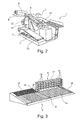
Figure 2 shows a different perspective view of the device according tofigure 1 . -
Figure 3 shows a perspective of the support surface of the device according tofigure 1 . -
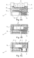
Figures 4A - 4C shows a top view of the support surface in different stages. -
Figure 1 shows an embodiment of the device 1 according to the invention placed in front of astack 2 ofboxes 3. - The device 1 has a
movable frame 4 having wheels 5. An arm 6 is arranged on themovable frame 4 and tiltable byhydraulic cylinders 7. Asupport surface 8 with agripper 9 is arranged at the free end of the arm 6. Aconveyor belt 10 is provided next to the arm 6 for transporting away unloadedboxes 3. -
Figure 2 shows the device offigure 1 from behind. On the side of the arm 6 opposite of theconveyor belt 10, aseat 11 is provided for an operator. Theseat 11 is provided withcontrols 12 for manually controlling the device 1. Furthermore, agangway 13 is provided behind theseat 11 for easy access of the operator. -
Figure 3 shows thesupport surface 8 in more detail. Thesupport surface 8 has two roller conveyors,first roller conveyor 14 in width direction of thesupport surface 8 and asecond roller conveyor 15 extending in depth direction of thesupport surface 8. Thefirst roller conveyor 14 defines the first surface zone of thesupport surface 8, while the second surface zone is defined by thesecond roller conveyor 15. - The
gripper 9 has a plurality ofsuction cups 16 arranged in a matrix on aframe part 17. Thisframe part 17 is guided overguide rails 18, such that thegripper 9 can move over thesupport surface 8. - A
scanning laser rangefinder 19 is arranged adjacent the interface between the first andsecond surface zones -
Figures 4A - 4C shows a top view of thesupport surface 8 in three different states. - In
figure 4A thegripper 9 is moved over thesupport surface 8 via the guide rails 18. Theframe part 17 is slidable arranged on aframe base 20, such that the gripper withsuction cups 16 is movable both in depth direction as in width direction of thesupport surface 8. - In
figure 4A thegripper 9 has gripped threeboxes 3 from a layer and pulls theseboxes 3 onto the support surface. - The
scanning laser rangefinder 19 constantly measures in several direction the distance between therangefinder 19 and the surrounding objects, such as theboxes 3 in order to determine the position of theseboxes 3. - As shown in
figure 4B , thegripper 9 has positioned the threeboxes 3 mainly in thefirst surface zone 14 and has returned to the home position in the left bottom corner of thesupport surface 8. - With the measurements of the
rangefinder 19, the controller (not shown) knows the position of theboxes 3 and controls the movement of theroller conveyor 14 such that the mostright box 3 is moved into thesecond surface zone 15/ - As soon as the
right box 8 is within the second surface zone, the movement of theroller conveyor 14 is stopped and the movement of theroller conveyor 15 is started, such that thefirst box 3 is transported away (seefigure 4C ) toward theconveyor belt 10. - When the controller detects based on the measurements of the
rangefinder 19, that thefirst box 3 has moved sufficiently far, the movement of thefirst roller conveyor 14 can be started again to bring thesecond box 3 within the second surface zone15. - In this way, the
boxes 3 are unloaded from a stack of boxes and moved with a certain spacing onto theconveyor belt 10 for further processing. - It would be possible with the device according to the invention to unload boxes from a stack, wherein other boxes are stacked on top of the unloaded boxes. This will speed up the unloading process.
Claims (9)
- Device for unloading stacked objects, like boxes, which device comprises:- a support surface having at least two adjacent surface zones, wherein a first surface zone is movable in a first direction and a second surface zone is movable in a second direction substantially perpendicular to the first direction;- gripper means movable over and parallel to the support surface for gripping and moving objects on the support surface;- position detection means for detecting the position of objects in the at least two adjacent surface zones; and- a controller for controlling at least the movement of the first surface zone and the second surface zone depending on position of the objects detected in the at least two surface zones.
- Device according to claim 1, wherein the first and second surface zones are formed by a first and second conveyor.
- Device according to claim 1, wherein a the first conveyor is a roller conveyor and wherein the gripper means comprise a first guide track arranged parallel and between the rollers for moving the gripper means in the axial direction of the rollers of the first conveyor.
- Device according to claim 3, wherein the gripper means further comprise a second guide track arranged on and perpendicular to the first guide track, for moving the gripper means in the transport direction of the first conveyor.
- Device according to any of the preceding claims, wherein the gripper means comprise an array of suction cups for suction to an object.
- Device according to any of the preceding claims, wherein the position detection means comprise a scanning laser rangefinder.
- Device according to claim 6, wherein the scanning laser rangefinder is arranged adjacent the interface between the first and second surface zones.
- Device according to any of the preceding claims, further comprising:- a movable frame to which the support surface is height adjustable arranged;- a third conveyor arranged between the movable frame and the second surface zone of the support surface for transporting away the unloaded objects.
- Method for unloading objects with a device according to any of the preceding claims, which method comprises the steps of:- moving the support surface adjacent a row of objects;- moving the gripper means over and parallel to the support surface to grip the row of objects and moving the objects onto the first surface zone of the support surface;- moving the first surface zone, such that the row of objects is moved towards the second surface zone, while detecting the position of the objects; and- controlling the movement of the first and second surface zones based on the detected positions, such that the objects are moved from the first surface zone onto the second surface zone and the objects are then moved over the second surface zone, while providing a spacing between the objects.
Priority Applications (2)
| Application Number | Priority Date | Filing Date | Title |
|---|---|---|---|
| EP13168693.3A EP2805903B1 (en) | 2013-05-22 | 2013-05-22 | Method and device for unloading stacked objects, like boxes |
| DK13168693.3T DK2805903T3 (en) | 2013-05-22 | 2013-05-22 | Method and device to unload the stacked articles, such as boxes |
Applications Claiming Priority (1)
| Application Number | Priority Date | Filing Date | Title |
|---|---|---|---|
| EP13168693.3A EP2805903B1 (en) | 2013-05-22 | 2013-05-22 | Method and device for unloading stacked objects, like boxes |
Publications (2)
| Publication Number | Publication Date |
|---|---|
| EP2805903A1 true EP2805903A1 (en) | 2014-11-26 |
| EP2805903B1 EP2805903B1 (en) | 2015-10-14 |
Family
ID=48537772
Family Applications (1)
| Application Number | Title | Priority Date | Filing Date |
|---|---|---|---|
| EP13168693.3A Active EP2805903B1 (en) | 2013-05-22 | 2013-05-22 | Method and device for unloading stacked objects, like boxes |
Country Status (2)
| Country | Link |
|---|---|
| EP (1) | EP2805903B1 (en) |
| DK (1) | DK2805903T3 (en) |
Cited By (10)
| Publication number | Priority date | Publication date | Assignee | Title |
|---|---|---|---|---|
| US9555982B2 (en) * | 2013-08-28 | 2017-01-31 | Intelligrated Headquarters Llc | Robotic carton unloader |
| WO2019001840A1 (en) * | 2017-06-28 | 2019-01-03 | Bayerische Motoren Werke Aktiengesellschaft | DEPALETTING DEVICE FOR DISPALETTING A TRANSPORT CONTAINER FROM A LOADING AREA |
| US10196219B2 (en) | 2014-11-28 | 2019-02-05 | Gebo Packaging Solutions Italy Srl | Detection device and method for a layer transfer device |
| US10336562B2 (en) | 2013-05-17 | 2019-07-02 | Intelligrated Headquarters, Llc | Robotic carton unloader |
| US10807805B2 (en) | 2013-05-17 | 2020-10-20 | Intelligrated Headquarters, Llc | Robotic carton unloader |
| US10829319B2 (en) | 2013-05-17 | 2020-11-10 | Intelligrated Headquarters, Llc | Robotic carton unloader |
| US10906742B2 (en) | 2016-10-20 | 2021-02-02 | Intelligrated Headquarters, Llc | Carton unloader tool for jam recovery |
| CN113233216A (en) * | 2021-06-08 | 2021-08-10 | 曜琅智慧科技产业(天津)有限公司 | Box drawing robot and using method thereof |
| US20230227272A1 (en) * | 2020-06-23 | 2023-07-20 | Haddad & Co S.A.L. (Holding Company) | Device and process for automated loading and unloading of parcels |
| WO2025174929A1 (en) * | 2024-02-15 | 2025-08-21 | Anyware Robotics Inc. | Multi-purpose robotic systems and methods for warehouse automation |
Citations (5)
| Publication number | Priority date | Publication date | Assignee | Title |
|---|---|---|---|---|
| DE7313036U (en) * | 1973-08-23 | Faller S | Device for unloading pallets | |
| DE19719748A1 (en) * | 1997-05-09 | 1998-11-12 | Fraunhofer Ges Forschung | Device for handling piece goods, in particular parcels, for loading and unloading a loading space, and method for unloading a loading space |
| DE102004033437A1 (en) * | 2004-04-01 | 2005-10-20 | Christine Farrenkopf | Mechanical handling device for loading/unloading containers or warehouse racks has a jacking mast that inclines in the X-plane |
| EP1885636A1 (en) | 2005-05-09 | 2008-02-13 | Copal Development B.V. | Apparatus for unloading a cargo space |
| EP1893512B1 (en) * | 2005-05-05 | 2009-03-04 | Arisi S.R.L. | Automatic depalletizer |
-
2013
- 2013-05-22 EP EP13168693.3A patent/EP2805903B1/en active Active
- 2013-05-22 DK DK13168693.3T patent/DK2805903T3/en active
Patent Citations (6)
| Publication number | Priority date | Publication date | Assignee | Title |
|---|---|---|---|---|
| DE7313036U (en) * | 1973-08-23 | Faller S | Device for unloading pallets | |
| DE19719748A1 (en) * | 1997-05-09 | 1998-11-12 | Fraunhofer Ges Forschung | Device for handling piece goods, in particular parcels, for loading and unloading a loading space, and method for unloading a loading space |
| DE102004033437A1 (en) * | 2004-04-01 | 2005-10-20 | Christine Farrenkopf | Mechanical handling device for loading/unloading containers or warehouse racks has a jacking mast that inclines in the X-plane |
| EP1893512B1 (en) * | 2005-05-05 | 2009-03-04 | Arisi S.R.L. | Automatic depalletizer |
| EP1885636A1 (en) | 2005-05-09 | 2008-02-13 | Copal Development B.V. | Apparatus for unloading a cargo space |
| EP1885636B1 (en) * | 2005-05-09 | 2013-04-17 | Copal Development B.V. | Apparatus for unloading a cargo space |
Cited By (14)
| Publication number | Priority date | Publication date | Assignee | Title |
|---|---|---|---|---|
| US10807805B2 (en) | 2013-05-17 | 2020-10-20 | Intelligrated Headquarters, Llc | Robotic carton unloader |
| US10829319B2 (en) | 2013-05-17 | 2020-11-10 | Intelligrated Headquarters, Llc | Robotic carton unloader |
| US10336562B2 (en) | 2013-05-17 | 2019-07-02 | Intelligrated Headquarters, Llc | Robotic carton unloader |
| US10124967B2 (en) | 2013-08-28 | 2018-11-13 | Intelligrated Headquarters Llc | Robotic carton unloader |
| US9555982B2 (en) * | 2013-08-28 | 2017-01-31 | Intelligrated Headquarters Llc | Robotic carton unloader |
| US10196219B2 (en) | 2014-11-28 | 2019-02-05 | Gebo Packaging Solutions Italy Srl | Detection device and method for a layer transfer device |
| EP3025988B1 (en) * | 2014-11-28 | 2019-11-20 | Gebo Packaging Solutions Italy SRL | Detection device and method for a layer transfer device |
| US10906742B2 (en) | 2016-10-20 | 2021-02-02 | Intelligrated Headquarters, Llc | Carton unloader tool for jam recovery |
| WO2019001840A1 (en) * | 2017-06-28 | 2019-01-03 | Bayerische Motoren Werke Aktiengesellschaft | DEPALETTING DEVICE FOR DISPALETTING A TRANSPORT CONTAINER FROM A LOADING AREA |
| US11167940B2 (en) | 2017-06-28 | 2021-11-09 | Bayerische Motoren Werke Aktiengesellschaft | Depalletizing device for depalletizing a transport receptacle from a storage surface |
| US20230227272A1 (en) * | 2020-06-23 | 2023-07-20 | Haddad & Co S.A.L. (Holding Company) | Device and process for automated loading and unloading of parcels |
| US12122613B2 (en) * | 2020-06-23 | 2024-10-22 | Haddad & Co S.A.L. | Device and process for automated loading and unloading of parcels |
| CN113233216A (en) * | 2021-06-08 | 2021-08-10 | 曜琅智慧科技产业(天津)有限公司 | Box drawing robot and using method thereof |
| WO2025174929A1 (en) * | 2024-02-15 | 2025-08-21 | Anyware Robotics Inc. | Multi-purpose robotic systems and methods for warehouse automation |
Also Published As
| Publication number | Publication date |
|---|---|
| EP2805903B1 (en) | 2015-10-14 |
| DK2805903T3 (en) | 2015-12-07 |
Similar Documents
| Publication | Publication Date | Title |
|---|---|---|
| EP2805903B1 (en) | Method and device for unloading stacked objects, like boxes | |
| US12344488B2 (en) | Vision-assisted robotized depalletizer | |
| US6652014B2 (en) | Vacuum grip system for gripping an object, and handling apparatus for handling an object using a vacuum grip system | |
| KR101931787B1 (en) | Bot payload alignment and sensing | |
| US5265712A (en) | Method and apparatus for taking up articles | |
| JP2014177337A5 (en) | ||
| US11787640B2 (en) | Floor-bound continuous conveyor | |
| US9221605B2 (en) | Article transfer device and stacker crane having same | |
| US20230024496A1 (en) | Automated warehouse systems, assemblies, apparatuses, and methods for assembling mixed pallets and facilitating order picking | |
| CN105173761A (en) | Automatic bag opening machine for material bags stacked on pallets | |
| US11091330B2 (en) | Apparatus and method for depalletizing a loaded pallet | |
| US12595140B2 (en) | Intelligent robotized depalletizer | |
| KR101850811B1 (en) | Automatic apparatus for transporting and stacking board | |
| EP3778447B1 (en) | Machine for unstacking objects | |
| CN106029533B (en) | Apparatus and method for transferring a loading unit | |
| JP7161256B1 (en) | Loading method on truck and its loading device | |
| CN110494379B (en) | Depalletizing device for depalletizing transport containers from a loading surface and method for operating the same | |
| EP3257794A1 (en) | Glass processing table with separate loading and processing areas | |
| US20250145388A1 (en) | Systems and Methods for PALLETIZING AND DEPALLETIZING | |
| US20160039620A1 (en) | Unloading a Cylindrical Body from a Pallet | |
| CN115892885A (en) | Automatic incoming material manual microscope inspection operation equipment | |
| EP4674793A1 (en) | Depalletising system and method | |
| KR101975776B1 (en) | Stone loading apparatus having bais prevention function | |
| KR100835392B1 (en) | Loading / unloading device for sheet material | |
| JP7066393B2 (en) | Extrusion transfer device |
Legal Events
| Date | Code | Title | Description |
|---|---|---|---|
| PUAI | Public reference made under article 153(3) epc to a published international application that has entered the european phase |
Free format text: ORIGINAL CODE: 0009012 |
|
| 17P | Request for examination filed |
Effective date: 20130522 |
|
| AK | Designated contracting states |
Kind code of ref document: A1 Designated state(s): AL AT BE BG CH CY CZ DE DK EE ES FI FR GB GR HR HU IE IS IT LI LT LU LV MC MK MT NL NO PL PT RO RS SE SI SK SM TR |
|
| AX | Request for extension of the european patent |
Extension state: BA ME |
|
| R17P | Request for examination filed (corrected) |
Effective date: 20150505 |
|
| RBV | Designated contracting states (corrected) |
Designated state(s): AL AT BE BG CH CY CZ DE DK EE ES FI FR GB GR HR HU IE IS IT LI LT LU LV MC MK MT NL NO PL PT RO RS SE SI SK SM TR |
|
| GRAP | Despatch of communication of intention to grant a patent |
Free format text: ORIGINAL CODE: EPIDOSNIGR1 |
|
| RIC1 | Information provided on ipc code assigned before grant |
Ipc: B65G 61/00 20060101ALI20150603BHEP Ipc: B65G 59/04 20060101AFI20150603BHEP Ipc: B65G 67/24 20060101ALI20150603BHEP |
|
| INTG | Intention to grant announced |
Effective date: 20150623 |
|
| GRAS | Grant fee paid |
Free format text: ORIGINAL CODE: EPIDOSNIGR3 |
|
| GRAA | (expected) grant |
Free format text: ORIGINAL CODE: 0009210 |
|
| AK | Designated contracting states |
Kind code of ref document: B1 Designated state(s): AL AT BE BG CH CY CZ DE DK EE ES FI FR GB GR HR HU IE IS IT LI LT LU LV MC MK MT NL NO PL PT RO RS SE SI SK SM TR |
|
| REG | Reference to a national code |
Ref country code: GB Ref legal event code: FG4D |
|
| REG | Reference to a national code |
Ref country code: AT Ref legal event code: REF Ref document number: 754939 Country of ref document: AT Kind code of ref document: T Effective date: 20151015 Ref country code: CH Ref legal event code: EP |
|
| REG | Reference to a national code |
Ref country code: IE Ref legal event code: FG4D |
|
| REG | Reference to a national code |
Ref country code: DE Ref legal event code: R096 Ref document number: 602013003420 Country of ref document: DE |
|
| REG | Reference to a national code |
Ref country code: DK Ref legal event code: T3 Effective date: 20151130 |
|
| REG | Reference to a national code |
Ref country code: NL Ref legal event code: FP |
|
| REG | Reference to a national code |
Ref country code: LT Ref legal event code: MG4D |
|
| REG | Reference to a national code |
Ref country code: AT Ref legal event code: MK05 Ref document number: 754939 Country of ref document: AT Kind code of ref document: T Effective date: 20151014 |
|
| PG25 | Lapsed in a contracting state [announced via postgrant information from national office to epo] |
Ref country code: IT Free format text: LAPSE BECAUSE OF FAILURE TO SUBMIT A TRANSLATION OF THE DESCRIPTION OR TO PAY THE FEE WITHIN THE PRESCRIBED TIME-LIMIT Effective date: 20151014 Ref country code: IS Free format text: LAPSE BECAUSE OF FAILURE TO SUBMIT A TRANSLATION OF THE DESCRIPTION OR TO PAY THE FEE WITHIN THE PRESCRIBED TIME-LIMIT Effective date: 20160214 Ref country code: NO Free format text: LAPSE BECAUSE OF FAILURE TO SUBMIT A TRANSLATION OF THE DESCRIPTION OR TO PAY THE FEE WITHIN THE PRESCRIBED TIME-LIMIT Effective date: 20160114 Ref country code: LT Free format text: LAPSE BECAUSE OF FAILURE TO SUBMIT A TRANSLATION OF THE DESCRIPTION OR TO PAY THE FEE WITHIN THE PRESCRIBED TIME-LIMIT Effective date: 20151014 Ref country code: HR Free format text: LAPSE BECAUSE OF FAILURE TO SUBMIT A TRANSLATION OF THE DESCRIPTION OR TO PAY THE FEE WITHIN THE PRESCRIBED TIME-LIMIT Effective date: 20151014 Ref country code: ES Free format text: LAPSE BECAUSE OF FAILURE TO SUBMIT A TRANSLATION OF THE DESCRIPTION OR TO PAY THE FEE WITHIN THE PRESCRIBED TIME-LIMIT Effective date: 20151014 |
|
| REG | Reference to a national code |
Ref country code: FR Ref legal event code: PLFP Year of fee payment: 4 |
|
| PG25 | Lapsed in a contracting state [announced via postgrant information from national office to epo] |
Ref country code: LV Free format text: LAPSE BECAUSE OF FAILURE TO SUBMIT A TRANSLATION OF THE DESCRIPTION OR TO PAY THE FEE WITHIN THE PRESCRIBED TIME-LIMIT Effective date: 20151014 Ref country code: AT Free format text: LAPSE BECAUSE OF FAILURE TO SUBMIT A TRANSLATION OF THE DESCRIPTION OR TO PAY THE FEE WITHIN THE PRESCRIBED TIME-LIMIT Effective date: 20151014 Ref country code: RS Free format text: LAPSE BECAUSE OF FAILURE TO SUBMIT A TRANSLATION OF THE DESCRIPTION OR TO PAY THE FEE WITHIN THE PRESCRIBED TIME-LIMIT Effective date: 20151014 Ref country code: SE Free format text: LAPSE BECAUSE OF FAILURE TO SUBMIT A TRANSLATION OF THE DESCRIPTION OR TO PAY THE FEE WITHIN THE PRESCRIBED TIME-LIMIT Effective date: 20151014 Ref country code: PT Free format text: LAPSE BECAUSE OF FAILURE TO SUBMIT A TRANSLATION OF THE DESCRIPTION OR TO PAY THE FEE WITHIN THE PRESCRIBED TIME-LIMIT Effective date: 20160215 Ref country code: GR Free format text: LAPSE BECAUSE OF FAILURE TO SUBMIT A TRANSLATION OF THE DESCRIPTION OR TO PAY THE FEE WITHIN THE PRESCRIBED TIME-LIMIT Effective date: 20160115 Ref country code: FI Free format text: LAPSE BECAUSE OF FAILURE TO SUBMIT A TRANSLATION OF THE DESCRIPTION OR TO PAY THE FEE WITHIN THE PRESCRIBED TIME-LIMIT Effective date: 20151014 Ref country code: PL Free format text: LAPSE BECAUSE OF FAILURE TO SUBMIT A TRANSLATION OF THE DESCRIPTION OR TO PAY THE FEE WITHIN THE PRESCRIBED TIME-LIMIT Effective date: 20151014 |
|
| REG | Reference to a national code |
Ref country code: DE Ref legal event code: R097 Ref document number: 602013003420 Country of ref document: DE |
|
| PG25 | Lapsed in a contracting state [announced via postgrant information from national office to epo] |
Ref country code: CZ Free format text: LAPSE BECAUSE OF FAILURE TO SUBMIT A TRANSLATION OF THE DESCRIPTION OR TO PAY THE FEE WITHIN THE PRESCRIBED TIME-LIMIT Effective date: 20151014 |
|
| PLBE | No opposition filed within time limit |
Free format text: ORIGINAL CODE: 0009261 |
|
| STAA | Information on the status of an ep patent application or granted ep patent |
Free format text: STATUS: NO OPPOSITION FILED WITHIN TIME LIMIT |
|
| PG25 | Lapsed in a contracting state [announced via postgrant information from national office to epo] |
Ref country code: SM Free format text: LAPSE BECAUSE OF FAILURE TO SUBMIT A TRANSLATION OF THE DESCRIPTION OR TO PAY THE FEE WITHIN THE PRESCRIBED TIME-LIMIT Effective date: 20151014 Ref country code: SK Free format text: LAPSE BECAUSE OF FAILURE TO SUBMIT A TRANSLATION OF THE DESCRIPTION OR TO PAY THE FEE WITHIN THE PRESCRIBED TIME-LIMIT Effective date: 20151014 Ref country code: EE Free format text: LAPSE BECAUSE OF FAILURE TO SUBMIT A TRANSLATION OF THE DESCRIPTION OR TO PAY THE FEE WITHIN THE PRESCRIBED TIME-LIMIT Effective date: 20151014 Ref country code: RO Free format text: LAPSE BECAUSE OF FAILURE TO SUBMIT A TRANSLATION OF THE DESCRIPTION OR TO PAY THE FEE WITHIN THE PRESCRIBED TIME-LIMIT Effective date: 20151014 |
|
| 26N | No opposition filed |
Effective date: 20160715 |
|
| PG25 | Lapsed in a contracting state [announced via postgrant information from national office to epo] |
Ref country code: SI Free format text: LAPSE BECAUSE OF FAILURE TO SUBMIT A TRANSLATION OF THE DESCRIPTION OR TO PAY THE FEE WITHIN THE PRESCRIBED TIME-LIMIT Effective date: 20151014 |
|
| PG25 | Lapsed in a contracting state [announced via postgrant information from national office to epo] |
Ref country code: LU Free format text: LAPSE BECAUSE OF FAILURE TO SUBMIT A TRANSLATION OF THE DESCRIPTION OR TO PAY THE FEE WITHIN THE PRESCRIBED TIME-LIMIT Effective date: 20160522 |
|
| REG | Reference to a national code |
Ref country code: FR Ref legal event code: PLFP Year of fee payment: 5 |
|
| REG | Reference to a national code |
Ref country code: FR Ref legal event code: PLFP Year of fee payment: 6 |
|
| PG25 | Lapsed in a contracting state [announced via postgrant information from national office to epo] |
Ref country code: HU Free format text: LAPSE BECAUSE OF FAILURE TO SUBMIT A TRANSLATION OF THE DESCRIPTION OR TO PAY THE FEE WITHIN THE PRESCRIBED TIME-LIMIT; INVALID AB INITIO Effective date: 20130522 |
|
| PG25 | Lapsed in a contracting state [announced via postgrant information from national office to epo] |
Ref country code: CY Free format text: LAPSE BECAUSE OF FAILURE TO SUBMIT A TRANSLATION OF THE DESCRIPTION OR TO PAY THE FEE WITHIN THE PRESCRIBED TIME-LIMIT Effective date: 20151014 Ref country code: MK Free format text: LAPSE BECAUSE OF FAILURE TO SUBMIT A TRANSLATION OF THE DESCRIPTION OR TO PAY THE FEE WITHIN THE PRESCRIBED TIME-LIMIT Effective date: 20151014 Ref country code: MC Free format text: LAPSE BECAUSE OF FAILURE TO SUBMIT A TRANSLATION OF THE DESCRIPTION OR TO PAY THE FEE WITHIN THE PRESCRIBED TIME-LIMIT Effective date: 20151014 Ref country code: MT Free format text: LAPSE BECAUSE OF NON-PAYMENT OF DUE FEES Effective date: 20160531 |
|
| PG25 | Lapsed in a contracting state [announced via postgrant information from national office to epo] |
Ref country code: BG Free format text: LAPSE BECAUSE OF FAILURE TO SUBMIT A TRANSLATION OF THE DESCRIPTION OR TO PAY THE FEE WITHIN THE PRESCRIBED TIME-LIMIT Effective date: 20151014 |
|
| PG25 | Lapsed in a contracting state [announced via postgrant information from national office to epo] |
Ref country code: TR Free format text: LAPSE BECAUSE OF FAILURE TO SUBMIT A TRANSLATION OF THE DESCRIPTION OR TO PAY THE FEE WITHIN THE PRESCRIBED TIME-LIMIT Effective date: 20151014 Ref country code: AL Free format text: LAPSE BECAUSE OF FAILURE TO SUBMIT A TRANSLATION OF THE DESCRIPTION OR TO PAY THE FEE WITHIN THE PRESCRIBED TIME-LIMIT Effective date: 20151014 |
|
| P01 | Opt-out of the competence of the unified patent court (upc) registered |
Effective date: 20230508 |
|
| P02 | Opt-out of the competence of the unified patent court (upc) changed |
Effective date: 20230512 |
|
| REG | Reference to a national code |
Ref country code: CH Ref legal event code: U11 Free format text: ST27 STATUS EVENT CODE: U-0-0-U10-U11 (AS PROVIDED BY THE NATIONAL OFFICE) Effective date: 20260601 |
|
| PGFP | Annual fee paid to national office [announced via postgrant information from national office to epo] |
Ref country code: NL Payment date: 20260518 Year of fee payment: 14 |
|
| PGFP | Annual fee paid to national office [announced via postgrant information from national office to epo] |
Ref country code: GB Payment date: 20260518 Year of fee payment: 14 Ref country code: DK Payment date: 20260526 Year of fee payment: 14 |
|
| PGFP | Annual fee paid to national office [announced via postgrant information from national office to epo] |
Ref country code: DE Payment date: 20260519 Year of fee payment: 14 |
|
| PGFP | Annual fee paid to national office [announced via postgrant information from national office to epo] |
Ref country code: IE Payment date: 20260518 Year of fee payment: 14 Ref country code: CH Payment date: 20260601 Year of fee payment: 14 Ref country code: BE Payment date: 20260518 Year of fee payment: 14 |
|
| PGFP | Annual fee paid to national office [announced via postgrant information from national office to epo] |
Ref country code: FR Payment date: 20260519 Year of fee payment: 14 |