EP2805840B1 - Kabinenluftfiltersystem für landwirtschaftliche Maschinen - Google Patents
Kabinenluftfiltersystem für landwirtschaftliche Maschinen Download PDFInfo
- Publication number
- EP2805840B1 EP2805840B1 EP14169677.3A EP14169677A EP2805840B1 EP 2805840 B1 EP2805840 B1 EP 2805840B1 EP 14169677 A EP14169677 A EP 14169677A EP 2805840 B1 EP2805840 B1 EP 2805840B1
- Authority
- EP
- European Patent Office
- Prior art keywords
- filter
- air
- cab
- filtration
- filtration system
- Prior art date
- Legal status (The legal status is an assumption and is not a legal conclusion. Google has not performed a legal analysis and makes no representation as to the accuracy of the status listed.)
- Active
Links
Images


Classifications
-
- B—PERFORMING OPERATIONS; TRANSPORTING
- B60—VEHICLES IN GENERAL
- B60H—ARRANGEMENTS OF HEATING, COOLING, VENTILATING OR OTHER AIR-TREATING DEVICES SPECIALLY ADAPTED FOR PASSENGER OR GOODS SPACES OF VEHICLES
- B60H1/00—Heating, cooling or ventilating devices
- B60H1/00357—Air-conditioning arrangements specially adapted for particular vehicles
- B60H1/00378—Air-conditioning arrangements specially adapted for particular vehicles for tractor or load vehicle cabins
-
- B—PERFORMING OPERATIONS; TRANSPORTING
- B60—VEHICLES IN GENERAL
- B60H—ARRANGEMENTS OF HEATING, COOLING, VENTILATING OR OTHER AIR-TREATING DEVICES SPECIALLY ADAPTED FOR PASSENGER OR GOODS SPACES OF VEHICLES
- B60H3/00—Other air-treating devices
- B60H3/06—Filtering
-
- B—PERFORMING OPERATIONS; TRANSPORTING
- B60—VEHICLES IN GENERAL
- B60H—ARRANGEMENTS OF HEATING, COOLING, VENTILATING OR OTHER AIR-TREATING DEVICES SPECIALLY ADAPTED FOR PASSENGER OR GOODS SPACES OF VEHICLES
- B60H3/00—Other air-treating devices
- B60H3/06—Filtering
- B60H3/0608—Filter arrangements in the air stream
- B60H3/0625—Filter arrangements in the air stream with provisions for by-passing the filter element
-
- B—PERFORMING OPERATIONS; TRANSPORTING
- B60—VEHICLES IN GENERAL
- B60H—ARRANGEMENTS OF HEATING, COOLING, VENTILATING OR OTHER AIR-TREATING DEVICES SPECIALLY ADAPTED FOR PASSENGER OR GOODS SPACES OF VEHICLES
- B60H3/00—Other air-treating devices
- B60H3/06—Filtering
- B60H3/0608—Filter arrangements in the air stream
- B60H3/0633—Filter arrangements in the air stream with provisions for regenerating or cleaning the filter element
Definitions
- the present invention relates to a cab air treatment apparatus for an agricultural machine, comprising an external air inlet, a filtration system connected downstream of the external air inlet, an air conditioning system connected downstream of the filtration system, and a cab air supply outlet connected downstream of the air conditioning system.
- the invention therefore proposes an apparatus of the type defined at the outset, in which the filtration system comprises, in order:
- the apparatus therefore, two different filters, with different functions, are provided.
- the possibility of bypassing the second filter enables this filter to be used only when really necessary, thus preserving the useful life and efficiency of the filter, while the first filter has the function of removing the coarser pollutants (dust and materials of larger size).
- the apparatus can still be used.
- the filtration system is decoupled from the air conditioning system.
- An electronic control system controls the various components of the apparatus, to provide the highest level of safety, flexibility and precision in the monitoring and control of these components.
- Figure 1 shows, schematically, a cab air treatment apparatus for agricultural machines according to the invention.
- the letter C indicates a cab of the agricultural machine, which, according to the regulations on exposure to hazardous substances, is required to be insulated from the external environment and pressurized with respect thereto (at least in the higher safety classes); in the drawing, Pc indicates the air pressure in the cab, while Pa represents the air pressure in the external environment.
- the air treatment apparatus essentially comprises an external air inlet 10 through which air is drawn at a pressure Pa from the external environment, a filtration system 20 connected downstream of the external air inlet 10, an air conditioning system 30 connected downstream of the filtration system 20, and a cab air supply outlet 40 connected downstream of the air conditioning system 30, through which treated air is supplied to the cab C at a pressure Pc.
- the filtration system 20 comprises, in sequence, a first filter 21, a bypass valve 22, a second filter 23 (for example, but not exclusively, an active carbon filter), which is associated with a bypass branch 24 arranged in parallel with it, a blower 25 and a deflecting valve 26.
- the first filter 20 is adapted to provide a mechanical filtration of dust, and serves to prevent premature clogging of the second filter 23 when the latter is active.
- the bypass valve 22 arranged upstream of the second filter 23 is adapted to selectively put the second filter 23, or a bypass branch 24 arranged in parallel with the second filter 23, in communication with the rest of the system.
- the filtration action of the second filter 23 can be enabled or disabled in order to permit the rational use of this filter; in fact, the latter one can be excluded from the air treatment apparatus when its filtration action is not required.
- the second filter 23 is a filter chosen from among known filters capable of suppressing:
- the second filter 23 can be removed (for maintenance or replacement, for example) without completely compromising the functionality of the system.
- the system will provide a filtration function using only the first filter 21.
- the second filter 23 is associated with an installation monitoring system (not shown) capable of detecting whether the second filter 23 is or is not installed in the seat provided.
- an installation monitoring system (not shown) capable of detecting whether the second filter 23 is or is not installed in the seat provided.
- the second filter 23 is also associated with a system for monitoring the saturation level, which is described more fully below.
- the blower 25 serves to compensate for the pressure drop due to the first filter 21, the second filter 23 and the lines associated with them, upstream of the blower 25, thus providing a desired pressurization downstream of the air supply outlet 40, and therefore in the cab C, so as to prevent the ingress of pollutants into the cab.
- fresh air enters the cab through the filters 21 and 23 only, providing a purifying action.
- the deflecting valve 26 has a main outlet 26a connected to the air conditioning system 30, and a discharge outlet 26b for cleaning the filtration system 20, said outlets being operable alternatively to one another.
- the outlet of the blower 25 is therefore put into communication through the deflecting valve 26 with the air conditioning system 30 or, alternatively, with the outside.
- the discharge outlet 26b therefore makes it possible to remove any pollutant remaining trapped in the system from upstream of the blower 25 to the valve 26 inclusive.
- the air conditioning system 30 is of a conventional type; fresh and recycled air to be supplied to the cab C is dehumidified and brought to the desired temperature by means of this system.
- the air conditioning system 30 may comprise an air mixing plenum 31, one or more blowers 32, an evaporator 33 and a heater 34.
- the cab C is also connected to the air mixing plenum 31 of the air conditioning system 30 through an air recycling line 50, provided with a shut-off valve 51.
- This valve also has the function of forcing the flow of fresh air, which is subsequently supplied to the cab, to pass through the air conditioning system 30.
- a differential pressure sensor 60 is also associated with the apparatus for the purpose of measuring the pressure difference Pc-Pa between the inside of the cab C and the external environment. This information is used to control the speed of the blower 25 to enable the cab pressurization to be controlled.
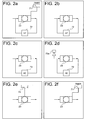
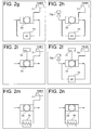
- a system for monitoring the saturation level is also associated with the second filter 23, for the purpose of monitoring the saturation level of this filter.
- This system can be used to monitor the safety conditions of the operator and prevents incorrect use of the filter; it may comprise various devices, for example (see Figures 2a-2n ):
- the monitoring system may also comprise a combination of the aforesaid devices, for example:
- the apparatus according to the invention is controlled by an electronic control unit 100.
- a controllable function of this control unit 100 is the control of a "key inserted" condition.
- the control unit 100 starts the cleaning and purification of components 21 to 26 of the filtration system.
- the deflecting valve 26 is set to a position in which the air flow entering from the inlet 10 is discharged to the outside, and is thus not supplied to the air conditioning system and to the cab C.
- the blower 25 impels the air towards the discharge outlet 26b of the valve 26 to clean components 21 to 26.
- This procedure is followed for a time interval determined on the basis of a mathematical model, measurements of the pollution level of the air (obtained from the system for monitoring the saturation of the filter 23), or both of these criteria.
- the control unit 100 can thus detect the positioning of the filter 23 in its housing.
- An electrical device (not shown) is fitted on the filter, on the corresponding housing, or on both of these, to detect the presence of the filter 23. This arrangement enables the system to be set to different statuses, particularly a "filter ON” status and a "filter OFF” status.
- the control unit 100 can also manage the pressurization control.
- the differential pressure sensor 60 measures the pressurization level Pc-Pa of the cab. This information is acquired from the control system that acts on the blower 25 to keep the pressurization at a safe level.
- the system is programmed on the basis of a mathematical model which allows for the measurements of pressure and of the operating characteristics of the components, particularly the blower, and implements a predetermined control strategy.
- the level of pressurization is displayed in the cab so that the operator can control it; if this level falls below a threshold value Pmin, an alarm signal is activated.
- the control unit 100 can also control the system for monitoring the saturation level of the second filter 23.
- the control system receives the data from the monitoring system and informs the operator of the status of the filter. If this status is unsatisfactory, owing to an anomaly, or the end of the filter life cycle, or a loss of filtration capacity, an alarm signal is activated and/or displayed, and a safety strategy is executed.
- control unit 100 executes a monitoring method comprising at least one of:
- the measurement of the period of use of the second filter 23 may comprise switching on time metering when the filter is in use, and switching off this time metering when the filter is in the rest condition.
- the control strategy can be implemented in such a way that the process of cleaning the filtration system is allowed for in the time metering.
- control unit 100 also controls the injector device 73a which introduces this substance.
- the filtration system 20 of the apparatus according to the invention may comprise two separate air intake lines, each comprising the first filter 21, the bypass valve 22 and the second filter 23, and both leading to a single blower 25.
- this configuration has a longer operating period (when one of the filters 23 is spent, the other is generally still operational); furthermore, there is a small air flow to be treated by each pair of filters, and therefore greater filtration efficiency.
Landscapes
- Engineering & Computer Science (AREA)
- Mechanical Engineering (AREA)
- Physics & Mathematics (AREA)
- Thermal Sciences (AREA)
- Air-Conditioning For Vehicles (AREA)
- Filtering Of Dispersed Particles In Gases (AREA)
Claims (3)
- Führerstandluftaufbereitungsvorrichtung für eine landwirtschaftliche Maschine, die einen externen Lufteinlass (10), ein Filtrationssystem (20), das in Flussrichtung nach dem externen Lufteinlass (10) angeschlossen ist, eine Klimaanlage (30), die in Flussrichtung nach dem Filtrationssystem (20) angeschlossen ist, und einen Führerstandluftzufuhrauslass (40) umfasst, der in Flussrichtung nach der Klimaanlage (30) angeschlossen ist, wobei das Filtrationssystem in dieser Reihenfolge folgende Merkmale aufweist:einen ersten Filter (21) zur Bereitstellung einer mechanischen Filtration von Staub,einen zweiten Filter (23) zur Bereitstellung einer Filtration von zumindest entweder Staub, Aerosolen oder Dämpfen, vor dem in Flussrichtung ein Umgehungsventil (22) angeordnet ist, um den zweiten Filter (23) oder eine parallel zu dem zweiten Filter (23) angeordnete Bypass-Verzweigung (24) selektiv in Verbindung mit dem System zu bringen.ein Gebläse (25) zur Bereitstellung einer gewünschten Druckbeaufschlagung nach dem Führerstandluftzufuhrauslass (40), undein Umlenkventil (26), das einen mit der Klimaanlage (30) verbundenen Hauptauslass (26a) und einen Ausstoßauslass (26b) zur Säuberung des Filtrationssystems (20) aufweist, wobei die Auslasse alternativ zueinander betriebsfähig sind.
- Vorrichtung gemäß Anspruch 1, die ferner eine Führerstandluftrückführungsleitung (50), die mit einem Einlass der Klimaanlage (30) verbunden ist, in Flussrichtung nach dem Filtrationssystem (20) aufweist.
- Vorrichtung gemäß Anspruch 1 oder Anspruch 2, die ferner einen Differenzialdrucksensor (60) zum Messen einer Differenz zwischen einem Druck (Pc) nach dem Führerstandluftzufuhrauslass (40) und dem Druck (Pa) der Außenluft aufweist.
Applications Claiming Priority (1)
| Application Number | Priority Date | Filing Date | Title |
|---|---|---|---|
| IT000418A ITTO20130418A1 (it) | 2013-05-24 | 2013-05-24 | Sistema di filtrazione aria in cabina per macchine agricole |
Publications (2)
| Publication Number | Publication Date |
|---|---|
| EP2805840A1 EP2805840A1 (de) | 2014-11-26 |
| EP2805840B1 true EP2805840B1 (de) | 2016-05-04 |
Family
ID=48877453
Family Applications (1)
| Application Number | Title | Priority Date | Filing Date |
|---|---|---|---|
| EP14169677.3A Active EP2805840B1 (de) | 2013-05-24 | 2014-05-23 | Kabinenluftfiltersystem für landwirtschaftliche Maschinen |
Country Status (3)
| Country | Link |
|---|---|
| US (1) | US9409460B2 (de) |
| EP (1) | EP2805840B1 (de) |
| IT (1) | ITTO20130418A1 (de) |
Families Citing this family (10)
| Publication number | Priority date | Publication date | Assignee | Title |
|---|---|---|---|---|
| CA2883150C (en) * | 2011-08-18 | 2019-03-05 | Greg Brian KNOWLES | Air contaminant filtration system for a cabin |
| WO2016005401A1 (en) * | 2014-07-09 | 2016-01-14 | Cnh Industrial Italia S.P.A. | Selective filtration level air treatment system. |
| KR20160024536A (ko) * | 2014-08-26 | 2016-03-07 | 기아자동차주식회사 | 차량 내부 공기 정화를 위한 텔레매틱스 단말 및 그 제어 방법 |
| US10603983B2 (en) | 2017-03-13 | 2020-03-31 | Cnh Industrial America Llc | Pressurization system for an agricultural machine |
| GB201721500D0 (en) * | 2017-12-20 | 2018-01-31 | Agco Int Gmbh | Air treatment apparatus |
| DE102018206111A1 (de) | 2018-04-20 | 2019-10-24 | Deere & Company | Dachstruktur |
| EP3636467B1 (de) * | 2018-10-10 | 2023-02-22 | Kubota Corporation | Nutzfahrzeug |
| US11932080B2 (en) * | 2020-08-20 | 2024-03-19 | Denso International America, Inc. | Diagnostic and recirculation control systems and methods |
| CN113212098B (zh) * | 2021-04-23 | 2022-11-01 | 太原科技大学 | 一种满足热舒适度和增压要求的驾驶室及其控制方法 |
| US12017508B2 (en) * | 2021-09-02 | 2024-06-25 | Apple Inc. | Climate control system |
Family Cites Families (11)
| Publication number | Priority date | Publication date | Assignee | Title |
|---|---|---|---|---|
| US3670808A (en) * | 1970-02-09 | 1972-06-20 | Caterpillar Tractor Co | Heating and air-conditioning system for construction equipment |
| FR2541945B1 (fr) * | 1983-03-04 | 1987-08-21 | Loubet Eliane | Conditionneur d'air pour cabines de travail en atmosphere polluee |
| DE3642443A1 (de) * | 1986-12-12 | 1988-06-23 | Audi Ag | Belueftungsvorrichtung mit einem filter fuer ein personenkraftfahrzeug |
| US4784048A (en) * | 1987-10-22 | 1988-11-15 | Nelson Robert M | Filter system incorporated with cab for orchard sprayer |
| DE3940363A1 (de) * | 1989-12-06 | 1991-06-13 | Bayerische Motoren Werke Ag | Belueftungsanlage fuer kraftfahrzeuginnenraeume |
| JP3325414B2 (ja) * | 1994-12-28 | 2002-09-17 | 日立建機株式会社 | 空調用ダクト |
| SE506970C2 (sv) * | 1996-07-23 | 1998-03-09 | Volvo Ab | Klimatanläggning för motorfordon |
| DE19651669C1 (de) * | 1996-12-12 | 1997-12-04 | Daimler Benz Ag | Luftansaugvorrichtung für eine Heizungs- oder Klimaanlage von Kraftfahrzeugen |
| US6620039B1 (en) * | 2002-05-30 | 2003-09-16 | Paccar Inc. | Method and apparatus for providing fresh air to a truck sleeper box |
| DE102009003300A1 (de) * | 2009-05-20 | 2010-11-25 | Deere & Company, Moline | Belüftungseinrichtung für eine Fahrerkabine eines Kraftfahrzeugs |
| WO2014143307A1 (en) * | 2013-03-15 | 2014-09-18 | Rodney Koch | Single exchanger hvac unit and power machines using the same |
-
2013
- 2013-05-24 IT IT000418A patent/ITTO20130418A1/it unknown
-
2014
- 2014-05-22 US US14/285,377 patent/US9409460B2/en active Active
- 2014-05-23 EP EP14169677.3A patent/EP2805840B1/de active Active
Also Published As
| Publication number | Publication date |
|---|---|
| ITTO20130418A1 (it) | 2014-11-25 |
| US20140345467A1 (en) | 2014-11-27 |
| US9409460B2 (en) | 2016-08-09 |
| EP2805840A1 (de) | 2014-11-26 |
Similar Documents
| Publication | Publication Date | Title |
|---|---|---|
| EP2805840B1 (de) | Kabinenluftfiltersystem für landwirtschaftliche Maschinen | |
| EP4331881B1 (de) | Vorrichtung zum kombinierten reduzieren des kohlendioxid- und wasser- bzw. feuchtegehalts, kraftfahrzeug und verfahren | |
| US9273585B2 (en) | System and method for regenerating an auxiliary power unit exhaust filter | |
| CN102770745B (zh) | 用于测量机动车废气的颗粒浓度的装置 | |
| DE102015103547B4 (de) | Abgasbehandlungssystem und elektronisches steuermodul | |
| WO2018006988A1 (de) | Klimaanlage für ein fahrzeug | |
| CN105275690B (zh) | 燃料过滤器异常检测装置 | |
| WO2005029506A2 (en) | Nbc filtration unit providing unfiltered and filtered air paths | |
| EP1371982A1 (de) | Vorrichtung und Methode zur Messung von Atemalkohol | |
| CN108105941A (zh) | 空气净化设备及其滤网寿命估算方法、装置 | |
| WO2015159248A1 (en) | Cabin pressurazation system for agricultural machines, having a filteration system | |
| EP1422089A2 (de) | Verfahren zur Bekämpfung von Gerüchen und/oder Schadstoffen im Fahrzeuginnenraum | |
| DE60201727T2 (de) | Luftfilter im Klimaanlage für Kraftfahrzeuge und automatisches Verfahren zur Regenerierung | |
| DE102005012502C5 (de) | Vorrichtung zur Überwachung eines Filters, Belüftungs-, Heizungs- und/oder Klimaanlage für ein Kraftfahrzeug sowie Verfahren zur Filterüberwachung | |
| CN105817091B (zh) | 用于监控过滤器寿命的方法和装置 | |
| CN107921846A (zh) | 空气净化系统和用于控制空气净化系统的方法 | |
| CN102762972A (zh) | 用于确定散射光测量设备的测量结果质量的方法和装置 | |
| EP3445655B1 (de) | Rückgewinnungsvorrichtung und verfahren für lufttrennungsmodul zur inertgaserzeugung an bord | |
| US20090211601A1 (en) | System for extracting vapor and particulates from a flow of a liquid and an air stream | |
| EP2052768B1 (de) | Luftfiltersystem für ein Nutzfahrzeug und Verfahren zur Steuerung des Luftfiltersystems | |
| US20200318879A1 (en) | Apparatus for maintaining a motor vehicle air conditioning system provided with carbon dioxide and operating method thereof | |
| KR20180083113A (ko) | 필터 오염도를 실시간으로 확인할 수 있는 에어컨 | |
| DE202017006977U1 (de) | Saugvorrichtung mit einer Filtereinrichtung | |
| DE102018107216A1 (de) | Fahrzeugheizsystem | |
| DE102013203001A1 (de) | Belüftungsanlage für ein Fahrzeug |
Legal Events
| Date | Code | Title | Description |
|---|---|---|---|
| PUAI | Public reference made under article 153(3) epc to a published international application that has entered the european phase |
Free format text: ORIGINAL CODE: 0009012 |
|
| 17P | Request for examination filed |
Effective date: 20140523 |
|
| AK | Designated contracting states |
Kind code of ref document: A1 Designated state(s): AL AT BE BG CH CY CZ DE DK EE ES FI FR GB GR HR HU IE IS IT LI LT LU LV MC MK MT NL NO PL PT RO RS SE SI SK SM TR |
|
| AX | Request for extension of the european patent |
Extension state: BA ME |
|
| RIN1 | Information on inventor provided before grant (corrected) |
Inventor name: VIGLIONE, MICHELE Inventor name: SCARRONE, PIERO |
|
| R17P | Request for examination filed (corrected) |
Effective date: 20150520 |
|
| RBV | Designated contracting states (corrected) |
Designated state(s): AL AT BE BG CH CY CZ DE DK EE ES FI FR GB GR HR HU IE IS IT LI LT LU LV MC MK MT NL NO PL PT RO RS SE SI SK SM TR |
|
| GRAP | Despatch of communication of intention to grant a patent |
Free format text: ORIGINAL CODE: EPIDOSNIGR1 |
|
| INTG | Intention to grant announced |
Effective date: 20151117 |
|
| GRAS | Grant fee paid |
Free format text: ORIGINAL CODE: EPIDOSNIGR3 |
|
| GRAA | (expected) grant |
Free format text: ORIGINAL CODE: 0009210 |
|
| AK | Designated contracting states |
Kind code of ref document: B1 Designated state(s): AL AT BE BG CH CY CZ DE DK EE ES FI FR GB GR HR HU IE IS IT LI LT LU LV MC MK MT NL NO PL PT RO RS SE SI SK SM TR |
|
| REG | Reference to a national code |
Ref country code: GB Ref legal event code: FG4D |
|
| REG | Reference to a national code |
Ref country code: CH Ref legal event code: EP |
|
| REG | Reference to a national code |
Ref country code: AT Ref legal event code: REF Ref document number: 796576 Country of ref document: AT Kind code of ref document: T Effective date: 20160515 |
|
| REG | Reference to a national code |
Ref country code: IE Ref legal event code: FG4D |
|
| REG | Reference to a national code |
Ref country code: DE Ref legal event code: R096 Ref document number: 602014001776 Country of ref document: DE |
|
| REG | Reference to a national code |
Ref country code: FR Ref legal event code: PLFP Year of fee payment: 3 |
|
| REG | Reference to a national code |
Ref country code: NL Ref legal event code: MP Effective date: 20160504 |
|
| REG | Reference to a national code |
Ref country code: LT Ref legal event code: MG4D |
|
| PG25 | Lapsed in a contracting state [announced via postgrant information from national office to epo] |
Ref country code: NO Free format text: LAPSE BECAUSE OF FAILURE TO SUBMIT A TRANSLATION OF THE DESCRIPTION OR TO PAY THE FEE WITHIN THE PRESCRIBED TIME-LIMIT Effective date: 20160804 Ref country code: LT Free format text: LAPSE BECAUSE OF FAILURE TO SUBMIT A TRANSLATION OF THE DESCRIPTION OR TO PAY THE FEE WITHIN THE PRESCRIBED TIME-LIMIT Effective date: 20160504 Ref country code: NL Free format text: LAPSE BECAUSE OF FAILURE TO SUBMIT A TRANSLATION OF THE DESCRIPTION OR TO PAY THE FEE WITHIN THE PRESCRIBED TIME-LIMIT Effective date: 20160504 |
|
| REG | Reference to a national code |
Ref country code: AT Ref legal event code: MK05 Ref document number: 796576 Country of ref document: AT Kind code of ref document: T Effective date: 20160504 |
|
| PG25 | Lapsed in a contracting state [announced via postgrant information from national office to epo] |
Ref country code: GR Free format text: LAPSE BECAUSE OF FAILURE TO SUBMIT A TRANSLATION OF THE DESCRIPTION OR TO PAY THE FEE WITHIN THE PRESCRIBED TIME-LIMIT Effective date: 20160805 Ref country code: SE Free format text: LAPSE BECAUSE OF FAILURE TO SUBMIT A TRANSLATION OF THE DESCRIPTION OR TO PAY THE FEE WITHIN THE PRESCRIBED TIME-LIMIT Effective date: 20160504 Ref country code: ES Free format text: LAPSE BECAUSE OF FAILURE TO SUBMIT A TRANSLATION OF THE DESCRIPTION OR TO PAY THE FEE WITHIN THE PRESCRIBED TIME-LIMIT Effective date: 20160504 Ref country code: HR Free format text: LAPSE BECAUSE OF FAILURE TO SUBMIT A TRANSLATION OF THE DESCRIPTION OR TO PAY THE FEE WITHIN THE PRESCRIBED TIME-LIMIT Effective date: 20160504 Ref country code: LV Free format text: LAPSE BECAUSE OF FAILURE TO SUBMIT A TRANSLATION OF THE DESCRIPTION OR TO PAY THE FEE WITHIN THE PRESCRIBED TIME-LIMIT Effective date: 20160504 Ref country code: RS Free format text: LAPSE BECAUSE OF FAILURE TO SUBMIT A TRANSLATION OF THE DESCRIPTION OR TO PAY THE FEE WITHIN THE PRESCRIBED TIME-LIMIT Effective date: 20160504 Ref country code: PT Free format text: LAPSE BECAUSE OF FAILURE TO SUBMIT A TRANSLATION OF THE DESCRIPTION OR TO PAY THE FEE WITHIN THE PRESCRIBED TIME-LIMIT Effective date: 20160905 |
|
| PG25 | Lapsed in a contracting state [announced via postgrant information from national office to epo] |
Ref country code: IT Free format text: LAPSE BECAUSE OF FAILURE TO SUBMIT A TRANSLATION OF THE DESCRIPTION OR TO PAY THE FEE WITHIN THE PRESCRIBED TIME-LIMIT Effective date: 20160504 Ref country code: BE Free format text: LAPSE BECAUSE OF NON-PAYMENT OF DUE FEES Effective date: 20160531 |
|
| PG25 | Lapsed in a contracting state [announced via postgrant information from national office to epo] |
Ref country code: DK Free format text: LAPSE BECAUSE OF FAILURE TO SUBMIT A TRANSLATION OF THE DESCRIPTION OR TO PAY THE FEE WITHIN THE PRESCRIBED TIME-LIMIT Effective date: 20160504 Ref country code: EE Free format text: LAPSE BECAUSE OF FAILURE TO SUBMIT A TRANSLATION OF THE DESCRIPTION OR TO PAY THE FEE WITHIN THE PRESCRIBED TIME-LIMIT Effective date: 20160504 Ref country code: RO Free format text: LAPSE BECAUSE OF FAILURE TO SUBMIT A TRANSLATION OF THE DESCRIPTION OR TO PAY THE FEE WITHIN THE PRESCRIBED TIME-LIMIT Effective date: 20160504 Ref country code: CZ Free format text: LAPSE BECAUSE OF FAILURE TO SUBMIT A TRANSLATION OF THE DESCRIPTION OR TO PAY THE FEE WITHIN THE PRESCRIBED TIME-LIMIT Effective date: 20160504 Ref country code: SK Free format text: LAPSE BECAUSE OF FAILURE TO SUBMIT A TRANSLATION OF THE DESCRIPTION OR TO PAY THE FEE WITHIN THE PRESCRIBED TIME-LIMIT Effective date: 20160504 |
|
| REG | Reference to a national code |
Ref country code: DE Ref legal event code: R097 Ref document number: 602014001776 Country of ref document: DE |
|
| REG | Reference to a national code |
Ref country code: IE Ref legal event code: MM4A |
|
| PG25 | Lapsed in a contracting state [announced via postgrant information from national office to epo] |
Ref country code: PL Free format text: LAPSE BECAUSE OF FAILURE TO SUBMIT A TRANSLATION OF THE DESCRIPTION OR TO PAY THE FEE WITHIN THE PRESCRIBED TIME-LIMIT Effective date: 20160504 Ref country code: SM Free format text: LAPSE BECAUSE OF FAILURE TO SUBMIT A TRANSLATION OF THE DESCRIPTION OR TO PAY THE FEE WITHIN THE PRESCRIBED TIME-LIMIT Effective date: 20160504 Ref country code: BE Free format text: LAPSE BECAUSE OF FAILURE TO SUBMIT A TRANSLATION OF THE DESCRIPTION OR TO PAY THE FEE WITHIN THE PRESCRIBED TIME-LIMIT Effective date: 20160504 Ref country code: AT Free format text: LAPSE BECAUSE OF FAILURE TO SUBMIT A TRANSLATION OF THE DESCRIPTION OR TO PAY THE FEE WITHIN THE PRESCRIBED TIME-LIMIT Effective date: 20160504 |
|
| PLBE | No opposition filed within time limit |
Free format text: ORIGINAL CODE: 0009261 |
|
| STAA | Information on the status of an ep patent application or granted ep patent |
Free format text: STATUS: NO OPPOSITION FILED WITHIN TIME LIMIT |
|
| PG25 | Lapsed in a contracting state [announced via postgrant information from national office to epo] |
Ref country code: MC Free format text: LAPSE BECAUSE OF FAILURE TO SUBMIT A TRANSLATION OF THE DESCRIPTION OR TO PAY THE FEE WITHIN THE PRESCRIBED TIME-LIMIT Effective date: 20160504 |
|
| 26N | No opposition filed |
Effective date: 20170207 |
|
| REG | Reference to a national code |
Ref country code: FR Ref legal event code: PLFP Year of fee payment: 4 |
|
| PG25 | Lapsed in a contracting state [announced via postgrant information from national office to epo] |
Ref country code: SI Free format text: LAPSE BECAUSE OF FAILURE TO SUBMIT A TRANSLATION OF THE DESCRIPTION OR TO PAY THE FEE WITHIN THE PRESCRIBED TIME-LIMIT Effective date: 20160504 Ref country code: IE Free format text: LAPSE BECAUSE OF NON-PAYMENT OF DUE FEES Effective date: 20160523 |
|
| REG | Reference to a national code |
Ref country code: CH Ref legal event code: PL |
|
| PG25 | Lapsed in a contracting state [announced via postgrant information from national office to epo] |
Ref country code: CH Free format text: LAPSE BECAUSE OF NON-PAYMENT OF DUE FEES Effective date: 20170531 Ref country code: LI Free format text: LAPSE BECAUSE OF NON-PAYMENT OF DUE FEES Effective date: 20170531 |
|
| PG25 | Lapsed in a contracting state [announced via postgrant information from national office to epo] |
Ref country code: HU Free format text: LAPSE BECAUSE OF FAILURE TO SUBMIT A TRANSLATION OF THE DESCRIPTION OR TO PAY THE FEE WITHIN THE PRESCRIBED TIME-LIMIT; INVALID AB INITIO Effective date: 20140523 |
|
| REG | Reference to a national code |
Ref country code: FR Ref legal event code: PLFP Year of fee payment: 5 |
|
| PG25 | Lapsed in a contracting state [announced via postgrant information from national office to epo] |
Ref country code: MT Free format text: LAPSE BECAUSE OF NON-PAYMENT OF DUE FEES Effective date: 20160531 Ref country code: CY Free format text: LAPSE BECAUSE OF FAILURE TO SUBMIT A TRANSLATION OF THE DESCRIPTION OR TO PAY THE FEE WITHIN THE PRESCRIBED TIME-LIMIT Effective date: 20160504 Ref country code: MK Free format text: LAPSE BECAUSE OF FAILURE TO SUBMIT A TRANSLATION OF THE DESCRIPTION OR TO PAY THE FEE WITHIN THE PRESCRIBED TIME-LIMIT Effective date: 20160504 Ref country code: IS Free format text: LAPSE BECAUSE OF FAILURE TO SUBMIT A TRANSLATION OF THE DESCRIPTION OR TO PAY THE FEE WITHIN THE PRESCRIBED TIME-LIMIT Effective date: 20160504 Ref country code: LU Free format text: LAPSE BECAUSE OF NON-PAYMENT OF DUE FEES Effective date: 20160523 |
|
| PG25 | Lapsed in a contracting state [announced via postgrant information from national office to epo] |
Ref country code: BG Free format text: LAPSE BECAUSE OF FAILURE TO SUBMIT A TRANSLATION OF THE DESCRIPTION OR TO PAY THE FEE WITHIN THE PRESCRIBED TIME-LIMIT Effective date: 20160504 |
|
| PG25 | Lapsed in a contracting state [announced via postgrant information from national office to epo] |
Ref country code: AL Free format text: LAPSE BECAUSE OF FAILURE TO SUBMIT A TRANSLATION OF THE DESCRIPTION OR TO PAY THE FEE WITHIN THE PRESCRIBED TIME-LIMIT Effective date: 20160504 |
|
| GBPC | Gb: european patent ceased through non-payment of renewal fee |
Effective date: 20180523 |
|
| PG25 | Lapsed in a contracting state [announced via postgrant information from national office to epo] |
Ref country code: GB Free format text: LAPSE BECAUSE OF NON-PAYMENT OF DUE FEES Effective date: 20180523 |
|
| PGFP | Annual fee paid to national office [announced via postgrant information from national office to epo] |
Ref country code: FI Payment date: 20250515 Year of fee payment: 12 |
|
| PGFP | Annual fee paid to national office [announced via postgrant information from national office to epo] |
Ref country code: DE Payment date: 20250523 Year of fee payment: 12 |
|
| PGFP | Annual fee paid to national office [announced via postgrant information from national office to epo] |
Ref country code: FR Payment date: 20250430 Year of fee payment: 12 |
|
| PGFP | Annual fee paid to national office [announced via postgrant information from national office to epo] |
Ref country code: TR Payment date: 20250512 Year of fee payment: 12 |