EP2805840A1 - Cabin air filtration system for agricultural machines - Google Patents
Cabin air filtration system for agricultural machines Download PDFInfo
- Publication number
- EP2805840A1 EP2805840A1 EP20140169677 EP14169677A EP2805840A1 EP 2805840 A1 EP2805840 A1 EP 2805840A1 EP 20140169677 EP20140169677 EP 20140169677 EP 14169677 A EP14169677 A EP 14169677A EP 2805840 A1 EP2805840 A1 EP 2805840A1
- Authority
- EP
- European Patent Office
- Prior art keywords
- filter
- air
- cab
- filtration
- filtration system
- Prior art date
- Legal status (The legal status is an assumption and is not a legal conclusion. Google has not performed a legal analysis and makes no representation as to the accuracy of the status listed.)
- Granted
Links
Images


Classifications
-
- B—PERFORMING OPERATIONS; TRANSPORTING
- B60—VEHICLES IN GENERAL
- B60H—ARRANGEMENTS OF HEATING, COOLING, VENTILATING OR OTHER AIR-TREATING DEVICES SPECIALLY ADAPTED FOR PASSENGER OR GOODS SPACES OF VEHICLES
- B60H1/00—Heating, cooling or ventilating devices
- B60H1/00357—Air-conditioning arrangements specially adapted for particular vehicles
- B60H1/00378—Air-conditioning arrangements specially adapted for particular vehicles for tractor or load vehicle cabins
-
- B—PERFORMING OPERATIONS; TRANSPORTING
- B60—VEHICLES IN GENERAL
- B60H—ARRANGEMENTS OF HEATING, COOLING, VENTILATING OR OTHER AIR-TREATING DEVICES SPECIALLY ADAPTED FOR PASSENGER OR GOODS SPACES OF VEHICLES
- B60H3/00—Other air-treating devices
- B60H3/06—Filtering
-
- B—PERFORMING OPERATIONS; TRANSPORTING
- B60—VEHICLES IN GENERAL
- B60H—ARRANGEMENTS OF HEATING, COOLING, VENTILATING OR OTHER AIR-TREATING DEVICES SPECIALLY ADAPTED FOR PASSENGER OR GOODS SPACES OF VEHICLES
- B60H3/00—Other air-treating devices
- B60H3/06—Filtering
- B60H3/0608—Filter arrangements in the air stream
- B60H3/0625—Filter arrangements in the air stream with provisions for by-passing the filter element
-
- B—PERFORMING OPERATIONS; TRANSPORTING
- B60—VEHICLES IN GENERAL
- B60H—ARRANGEMENTS OF HEATING, COOLING, VENTILATING OR OTHER AIR-TREATING DEVICES SPECIALLY ADAPTED FOR PASSENGER OR GOODS SPACES OF VEHICLES
- B60H3/00—Other air-treating devices
- B60H3/06—Filtering
- B60H3/0608—Filter arrangements in the air stream
- B60H3/0633—Filter arrangements in the air stream with provisions for regenerating or cleaning the filter element
Definitions
- the present invention relates to a cab air treatment apparatus for an agricultural machine, comprising an external air inlet, a filtration system connected downstream of the external air inlet, an air conditioning system connected downstream of the filtration system, and a cab air supply outlet connected downstream of the air conditioning system.
- the invention therefore proposes an apparatus of the type defined at the outset, in which the filtration system comprises, in order:
- the apparatus therefore, two different filters, with different functions, are provided.
- the possibility of bypassing the second filter enables this filter to be used only when really necessary, thus preserving the useful life and efficiency of the filter, while the first filter has the function of removing the coarser pollutants (dust and materials of larger size).
- the apparatus can still be used.
- the filtration system is decoupled from the air conditioning system.
- An electronic control system controls the various components of the apparatus, to provide the highest level of safety, flexibility and precision in the monitoring and control of these components.
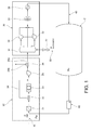
- Figure 1 shows, schematically, a cab air treatment apparatus for agricultural machines according to the invention.
- the letter C indicates a cab of the agricultural machine, which, according to the regulations on exposure to hazardous substances, is required to be insulated from the external environment and pressurized with respect thereto (at least in the higher safety classes); in the drawing, Pc indicates the air pressure in the cab, while Pa represents the air pressure in the external environment.
- the air treatment apparatus essentially comprises an external air inlet 10 through which air is drawn at a pressure Pa from the external environment, a filtration system 20 connected downstream of the external air inlet 10, an air conditioning system 30 connected downstream of the filtration system 20, and a cab air supply outlet 40 connected downstream of the air conditioning system 30, through which treated air is supplied to the cab C at a pressure Pc.
- the filtration system 20 comprises, in sequence, a first filter 21, a bypass valve 22, a second filter 23 (for example, but not exclusively, an active carbon filter), which is associated with a bypass branch 24 arranged in parallel with it, a blower 25 and a deflecting valve 26.
- the first filter 20 is adapted to provide a mechanical filtration of dust, and serves to prevent premature clogging of the second filter 23 when the latter is active.
- the bypass valve 22 arranged upstream of the second filter 23 is adapted to selectively put the second filter 23, or a bypass branch 24 arranged in parallel with the second filter 23, in communication with the rest of the system.
- the filtration action of the second filter 23 can be enabled or disabled in order to permit the rational use of this filter; in fact, the latter one can be excluded from the air treatment apparatus when its filtration action is not required.
- the second filter 23 is a filter chosen from among known filters capable of suppressing:
- the second filter 23 can be removed (for maintenance or replacement, for example) without completely compromising the functionality of the system.
- the system will provide a filtration function using only the first filter 21.
- the second filter 23 is associated with an installation monitoring system (not shown) capable of detecting whether the second filter 23 is or is not installed in the seat provided.
- an installation monitoring system (not shown) capable of detecting whether the second filter 23 is or is not installed in the seat provided.
- the second filter 23 is also associated with a system for monitoring the saturation level, which is described more fully below.
- the blower 25 serves to compensate for the pressure drop due to the first filter 21, the second filter 23 and the lines associated with them, upstream of the blower 25, thus providing a desired pressurization downstream of the air supply outlet 40, and therefore in the cab C, so as to prevent the ingress of pollutants into the cab.
- fresh air enters the cab through the filters 21 and 23 only, providing a purifying action.
- the deflecting valve 26 has a main outlet 26a connected to the air conditioning system 30, and a discharge outlet 26b for cleaning the filtration system 20, said outlets being operable alternatively to one another.
- the outlet of the blower 25 is therefore put into communication through the deflecting valve 26 with the air conditioning system 30 or, alternatively, with the outside.
- the discharge outlet 26b therefore makes it possible to remove any pollutant remaining trapped in the system from upstream of the blower 25 to the valve 26 inclusive.
- the air conditioning system 30 is of a conventional type; fresh and recycled air to be supplied to the cab C is dehumidified and brought to the desired temperature by means of this system.
- the air conditioning system 30 may comprise an air mixing plenum 31, one or more blowers 32, an evaporator 33 and a heater 34.
- the cab C is also connected to the air mixing plenum 31 of the air conditioning system 30 through an air recycling line 50, provided with a shut-off valve 51.
- This valve also has the function of forcing the flow of fresh air, which is subsequently supplied to the cab, to pass through the air conditioning system 30.
- a differential pressure sensor 60 is also associated with the apparatus for the purpose of measuring the pressure difference Pc-Pa between the inside of the cab C and the external environment. This information is used to control the speed of the blower 25 to enable the cab pressurization to be controlled.
- a system for monitoring the saturation level is also associated with the second filter 23, for the purpose of monitoring the saturation level of this filter.
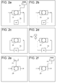
- This system can be used to monitor the safety conditions of the operator and prevents incorrect use of the filter; it may comprise various devices, for example (see Figures 2a-2n ):
- the monitoring system may also comprise a combination of the aforesaid devices, for example:
- the apparatus according to the invention is controlled by an electronic control unit 100.
- a controllable function of this control unit 100 is the control of a "key inserted" condition.
- the control unit 100 starts the cleaning and purification of components 21 to 26 of the filtration system.
- the deflecting valve 26 is set to a position in which the air flow entering from the inlet 10 is discharged to the outside, and is thus not supplied to the air conditioning system and to the cab C.
- the blower 25 impels the air towards the discharge outlet 26b of the valve 26 to clean components 21 to 26.
- This procedure is followed for a time interval determined on the basis of a mathematical model, measurements of the pollution level of the air (obtained from the system for monitoring the saturation of the filter 23), or both of these criteria.
- the control unit 100 can thus detect the positioning of the filter 23 in its housing.
- An electrical device (not shown) is fitted on the filter, on the corresponding housing, or on both of these, to detect the presence of the filter 23. This arrangement enables the system to be set to different statuses, particularly a "filter ON” status and a "filter OFF” status.
- the control unit 100 can also manage the pressurization control.
- the differential pressure sensor 60 measures the pressurization level Pc-Pa of the cab. This information is acquired from the control system that acts on the blower 25 to keep the pressurization at a safe level.
- the system is programmed on the basis of a mathematical model which allows for the measurements of pressure and of the operating characteristics of the components, particularly the blower, and implements a predetermined control strategy.
- the level of pressurization is displayed in the cab so that the operator can control it; if this level falls below a threshold value Pmin, an alarm signal is activated.
- the control unit 100 can also control the system for monitoring the saturation level of the second filter 23.
- the control system receives the data from the monitoring system and informs the operator of the status of the filter. If this status is unsatisfactory, owing to an anomaly, or the end of the filter life cycle, or a loss of filtration capacity, an alarm signal is activated and/or displayed, and a safety strategy is executed.
- control unit 100 executes a monitoring method comprising at least one of:
- the measurement of the period of use of the second filter 23 may comprise switching on time metering when the filter is in use, and switching off this time metering when the filter is in the rest condition.
- the control strategy can be implemented in such a way that the process of cleaning the filtration system is allowed for in the time metering.
- control unit 100 also controls the injector device 73a which introduces this substance.
- the filtration system 20 of the apparatus according to the invention may comprise two separate air intake lines, each comprising the first filter 21, the bypass valve 22 and the second filter 23, and both leading to a single blower 25.
- this configuration has a longer operating period (when one of the filters 23 is spent, the other is generally still operational); furthermore, there is a small air flow to be treated by each pair of filters, and therefore greater filtration efficiency.
Landscapes
- Engineering & Computer Science (AREA)
- Mechanical Engineering (AREA)
- Physics & Mathematics (AREA)
- Thermal Sciences (AREA)
- Air-Conditioning For Vehicles (AREA)
- Filtering Of Dispersed Particles In Gases (AREA)
Abstract
a first filter (21),
a second filter (23), upstream of which is arranged a bypass valve (22) for selectively putting the adsorption filter (23), or a bypass branch (24) arranged in parallel with the second filter (23), in communication with the system (20),
a blower (25) for providing a desired pressurization downstream of the cab air supply outlet (40), and
a deflecting valve (26) having a main outlet (26a) connected to the air conditioning system (30), and a discharge outlet (26b) for cleaning the filtration system (20), said outlets being operable alternatively to one another.
Description
- The present invention relates to a cab air treatment apparatus for an agricultural machine, comprising an external air inlet, a filtration system connected downstream of the external air inlet, an air conditioning system connected downstream of the filtration system, and a cab air supply outlet connected downstream of the air conditioning system.
- Conventional types of air treatment apparatus for agricultural machines provide dust filtration, but aerosols and vapours can, in practice, still flow freely into the vehicle cab. Furthermore, these known apparatus are inflexible, and it is difficult to use them to achieve satisfactory levels of pressurization in the cab, in particular if the latest standards are borne in mind.
- The invention therefore proposes an apparatus of the type defined at the outset, in which the filtration system comprises, in order:
- a first filter for providing mechanical filtration of dust,
- a second filter for providing filtration of at least one among dust, aerosols and vapours, upstream of which a bypass valve is arranged for selectively putting the second filter, or a bypass branch arranged in parallel with the second filter, in communication with the system,
- a blower for providing desired pressurization downstream of the cab air supply outlet, and
- a deflecting valve having a main outlet connected to the air conditioning system, and a discharge outlet for cleaning the filtration system, said outlets being operable alternatively to one another.
- According to the invention, therefore, two different filters, with different functions, are provided. The possibility of bypassing the second filter enables this filter to be used only when really necessary, thus preserving the useful life and efficiency of the filter, while the first filter has the function of removing the coarser pollutants (dust and materials of larger size). Moreover, even if the second filter is missing because it is undergoing maintenance or replacement or selection by the operator, the apparatus can still be used.
- It is also possible to pressurize the vehicle cab by using the blower of the filtration system, without the need to use the blower or blowers of the air conditioning system. In fact, in the system according to the invention the filtration system is decoupled from the air conditioning system. An electronic control system controls the various components of the apparatus, to provide the highest level of safety, flexibility and precision in the monitoring and control of these components.
- Preferred embodiments of the invention are defined in the dependent claims, which are to be considered as an integral part of the present description.
- Further characteristics and advantages of the apparatus according to the invention will be made clearer by the following detailed description of an embodiment of the invention, given with reference to the attached drawings which are provided purely as non-limiting illustrations, in which:
-
Figure 1 shows, schematically, an embodiment of an air treatment apparatus for agricultural machines according to the invention; -
Figures 2a to 2n show different strategies for monitoring a filter of the apparatus ofFigure 1 ; and -
Figure 3 is a schematic illustration of an architecture of an electronic control system of the apparatus ofFigure 1 . -
Figure 1 shows, schematically, a cab air treatment apparatus for agricultural machines according to the invention. The letter C indicates a cab of the agricultural machine, which, according to the regulations on exposure to hazardous substances, is required to be insulated from the external environment and pressurized with respect thereto (at least in the higher safety classes); in the drawing, Pc indicates the air pressure in the cab, while Pa represents the air pressure in the external environment. - The air treatment apparatus essentially comprises an
external air inlet 10 through which air is drawn at a pressure Pa from the external environment, afiltration system 20 connected downstream of theexternal air inlet 10, anair conditioning system 30 connected downstream of thefiltration system 20, and a cabair supply outlet 40 connected downstream of theair conditioning system 30, through which treated air is supplied to the cab C at a pressure Pc. - The
filtration system 20 comprises, in sequence, afirst filter 21, abypass valve 22, a second filter 23 (for example, but not exclusively, an active carbon filter), which is associated with abypass branch 24 arranged in parallel with it, ablower 25 and adeflecting valve 26. - The
first filter 20 is adapted to provide a mechanical filtration of dust, and serves to prevent premature clogging of thesecond filter 23 when the latter is active. - The
bypass valve 22 arranged upstream of thesecond filter 23 is adapted to selectively put thesecond filter 23, or abypass branch 24 arranged in parallel with thesecond filter 23, in communication with the rest of the system. Thus the filtration action of thesecond filter 23 can be enabled or disabled in order to permit the rational use of this filter; in fact, the latter one can be excluded from the air treatment apparatus when its filtration action is not required. - The
second filter 23 is a filter chosen from among known filters capable of suppressing: - i. Dust
- ii. Dust + aerosols
- iii. Dust + aerosols + vapours,
- Owing to the presence of the
bypass valve 22, thesecond filter 23 can be removed (for maintenance or replacement, for example) without completely compromising the functionality of the system. In this case, the system will provide a filtration function using only thefirst filter 21. - Preferably, the
second filter 23 is associated with an installation monitoring system (not shown) capable of detecting whether thesecond filter 23 is or is not installed in the seat provided. - The
second filter 23 is also associated with a system for monitoring the saturation level, which is described more fully below. - The
blower 25 serves to compensate for the pressure drop due to thefirst filter 21, thesecond filter 23 and the lines associated with them, upstream of theblower 25, thus providing a desired pressurization downstream of theair supply outlet 40, and therefore in the cab C, so as to prevent the ingress of pollutants into the cab. Thus fresh air enters the cab through thefilters - The deflecting
valve 26 has amain outlet 26a connected to theair conditioning system 30, and adischarge outlet 26b for cleaning thefiltration system 20, said outlets being operable alternatively to one another. The outlet of theblower 25 is therefore put into communication through the deflectingvalve 26 with theair conditioning system 30 or, alternatively, with the outside. Thedischarge outlet 26b therefore makes it possible to remove any pollutant remaining trapped in the system from upstream of theblower 25 to thevalve 26 inclusive. - The
air conditioning system 30 is of a conventional type; fresh and recycled air to be supplied to the cab C is dehumidified and brought to the desired temperature by means of this system. In a conventional way, theair conditioning system 30 may comprise anair mixing plenum 31, one ormore blowers 32, anevaporator 33 and aheater 34. - The cab C is also connected to the
air mixing plenum 31 of theair conditioning system 30 through anair recycling line 50, provided with a shut-offvalve 51. This valve also has the function of forcing the flow of fresh air, which is subsequently supplied to the cab, to pass through theair conditioning system 30. - A
differential pressure sensor 60 is also associated with the apparatus for the purpose of measuring the pressure difference Pc-Pa between the inside of the cab C and the external environment. This information is used to control the speed of theblower 25 to enable the cab pressurization to be controlled. - A system for monitoring the saturation level is also associated with the
second filter 23, for the purpose of monitoring the saturation level of this filter. This system can be used to monitor the safety conditions of the operator and prevents incorrect use of the filter; it may comprise various devices, for example (seeFigures 2a-2n ): - a timer 71 (
Fig. 2f ) for measuring a period of use of the filter; - one or more pressure sensors 72 (
Fig. 2b ) for measuring a pressure difference between the inlet and outlet of thefilter 23; - one or more concentration meters 73 (
Fig. 2c ) for measuring a difference in the concentration of a substance in the air, between the inlet and outlet of thefilter 23. This substance may be a pollutant, a component of the air, or a marker substance introduced into the air flow upstream of the filter by aninjector 73a (Fig. 2d ); - a temperature sensor 74 (
Fig. 2e ) for measuring a temperature of thefilter 23. In fact, it is known that the adsorption of a substance is an exothermic reaction, and therefore the measurement of the temperature can enable the saturation level of the filter to be evaluated; - a colouring substance which changes colour according to the chemical conditions of the filter;
- a
circuit 75 for measuring the electrical conductivity of the filter 23 (Fig. 2n ). - For greater reliability, the monitoring system may also comprise a combination of the aforesaid devices, for example:
- a
timer 71 and a pressure sensor 72 (Fig. 2a ); - a
timer 71 and concentration meters 73 (Fig. 2g ); - a
timer 71,concentration meters 73, and amarker substance injector 73a (Fig. 2g ); - a
timer 71 and a temperature sensor 74 (Fig. 2i ); - a
timer 71, atemperature sensor 74,concentration meters 73, and amarker substance injector 73a (Fig. 2l ); - a
timer 71 and a colouring substance which changes colour according to the chemical conditions of the filter; - a
timer 71 and acircuit 75 for measuring the electrical conductivity (Fig. 2n ). - With reference to
Figure 3 , the apparatus according to the invention is controlled by anelectronic control unit 100. - A controllable function of this
control unit 100 is the control of a "key inserted" condition. When the apparatus is started, thecontrol unit 100 starts the cleaning and purification ofcomponents 21 to 26 of the filtration system. In this condition, the deflectingvalve 26 is set to a position in which the air flow entering from theinlet 10 is discharged to the outside, and is thus not supplied to the air conditioning system and to the cab C. Thus theblower 25 impels the air towards thedischarge outlet 26b of thevalve 26 to cleancomponents 21 to 26. This procedure is followed for a time interval determined on the basis of a mathematical model, measurements of the pollution level of the air (obtained from the system for monitoring the saturation of the filter 23), or both of these criteria. - The
control unit 100 can thus detect the positioning of thefilter 23 in its housing. An electrical device (not shown) is fitted on the filter, on the corresponding housing, or on both of these, to detect the presence of thefilter 23. This arrangement enables the system to be set to different statuses, particularly a "filter ON" status and a "filter OFF" status. - The
control unit 100 can also manage the pressurization control. Thedifferential pressure sensor 60 measures the pressurization level Pc-Pa of the cab. This information is acquired from the control system that acts on theblower 25 to keep the pressurization at a safe level. For this purpose, the system is programmed on the basis of a mathematical model which allows for the measurements of pressure and of the operating characteristics of the components, particularly the blower, and implements a predetermined control strategy. The level of pressurization is displayed in the cab so that the operator can control it; if this level falls below a threshold value Pmin, an alarm signal is activated. - The
control unit 100 can also control the system for monitoring the saturation level of thesecond filter 23. On the basis of a mathematical model, the control system receives the data from the monitoring system and informs the operator of the status of the filter. If this status is unsatisfactory, owing to an anomaly, or the end of the filter life cycle, or a loss of filtration capacity, an alarm signal is activated and/or displayed, and a safety strategy is executed. - In particular, the
control unit 100 executes a monitoring method comprising at least one of: - a) measuring a period of use t_funz of the second filter 23 (by means of the timer 71), and comparing a measured value of the period of use with a threshold value of time associated with a predetermined saturation level of the filter,
- b) measuring a difference between values of a physical quantity, respectively upstream and downstream of the second filter 23 (the pressure difference ΔP and/or the difference in concentration ΔC of a substance in the air), and comparing a measured value of this difference with a threshold value of difference associated with a predetermined saturation level of the filter, and
- c) measuring a physical property (the temperature T or the electrical conductivity) of the
second filter 23, and comparing a measured value of this physical property with a threshold value of the property associated with a predetermined saturation level of the filter. - The measurement of the period of use of the
second filter 23 may comprise switching on time metering when the filter is in use, and switching off this time metering when the filter is in the rest condition. The control strategy can be implemented in such a way that the process of cleaning the filtration system is allowed for in the time metering. - If the control system provides for the measurement of the difference in concentration of a substance in the air, and if this substance is a marker substance suitably introduced by the
injector device 73a, thecontrol unit 100 also controls theinjector device 73a which introduces this substance. - According to a further embodiment of the invention, the
filtration system 20 of the apparatus according to the invention may comprise two separate air intake lines, each comprising thefirst filter 21, thebypass valve 22 and thesecond filter 23, and both leading to asingle blower 25. By comparison with the preceding embodiment, this configuration has a longer operating period (when one of thefilters 23 is spent, the other is generally still operational); furthermore, there is a small air flow to be treated by each pair of filters, and therefore greater filtration efficiency.
Claims (3)
- Cab air treatment apparatus for an agricultural machine, comprising an external air inlet (10), a filtration system (20) connected downstream of the external air inlet (10), an air conditioning system (30) connected downstream of the filtration system (20), and a cab air supply outlet (40) connected downstream of the air conditioning system (30), characterized in that said filtration system comprises, in order:a first filter (21) for providing a mechanical filtration of dust,a second filter (23) for providing a filtration of at least one among dust, aerosols and vapours, upstream of which a bypass valve (22) is arranged for selectively putting the second filter (23), or a bypass branch (24) arranged in parallel with the second filter (23), in communication with the system (20),a blower (25) for providing a desired pressurization downstream of the cab air supply outlet (40), anda deflecting valve (26) having a main outlet (26a) connected to the air conditioning system (30), and a discharge outlet (26b) for cleaning the filtration system (20), said outlets being operable alternatively to one another.
- Apparatus according to Claim 1, further comprising a cab air recycling line (50) connected to an inlet of the air conditioning system (30), downstream of the filtration system (20).
- Apparatus according to Claim 1 or 2, further comprising a differential pressure sensor (60) for measuring a difference between a pressure (Pc) downstream of the cab air supply outlet (40) and the pressure (Pa) of the external air.
Applications Claiming Priority (1)
| Application Number | Priority Date | Filing Date | Title |
|---|---|---|---|
| IT000418A ITTO20130418A1 (en) | 2013-05-24 | 2013-05-24 | AIR FILTRATION SYSTEM IN CABIN FOR AGRICULTURAL MACHINES |
Publications (2)
| Publication Number | Publication Date |
|---|---|
| EP2805840A1 true EP2805840A1 (en) | 2014-11-26 |
| EP2805840B1 EP2805840B1 (en) | 2016-05-04 |
Family
ID=48877453
Family Applications (1)
| Application Number | Title | Priority Date | Filing Date |
|---|---|---|---|
| EP14169677.3A Active EP2805840B1 (en) | 2013-05-24 | 2014-05-23 | Cabin air filtration system for agricultural machines |
Country Status (3)
| Country | Link |
|---|---|
| US (1) | US9409460B2 (en) |
| EP (1) | EP2805840B1 (en) |
| IT (1) | ITTO20130418A1 (en) |
Cited By (2)
| Publication number | Priority date | Publication date | Assignee | Title |
|---|---|---|---|---|
| EP3636467A1 (en) * | 2018-10-10 | 2020-04-15 | Kubota Corporation | Working vehicle |
| US20210078378A1 (en) * | 2017-12-20 | 2021-03-18 | Agco International Gmbh | Air treatment apparatus |
Families Citing this family (8)
| Publication number | Priority date | Publication date | Assignee | Title |
|---|---|---|---|---|
| EP2744676B1 (en) * | 2011-08-18 | 2020-07-29 | Knowles, Greg Brian | Air contaminant filtration system for a cabin |
| WO2016005401A1 (en) * | 2014-07-09 | 2016-01-14 | Cnh Industrial Italia S.P.A. | Selective filtration level air treatment system. |
| KR20160024536A (en) * | 2014-08-26 | 2016-03-07 | 기아자동차주식회사 | Telematics terminal for purificating air inside of vehicle and method for controlling the same |
| US10603983B2 (en) | 2017-03-13 | 2020-03-31 | Cnh Industrial America Llc | Pressurization system for an agricultural machine |
| DE102018206111A1 (en) | 2018-04-20 | 2019-10-24 | Deere & Company | roof structure |
| US11932080B2 (en) * | 2020-08-20 | 2024-03-19 | Denso International America, Inc. | Diagnostic and recirculation control systems and methods |
| CN113212098B (en) * | 2021-04-23 | 2022-11-01 | 太原科技大学 | Cab meeting thermal comfort degree and supercharging requirements and control method thereof |
| WO2023033946A1 (en) * | 2021-09-02 | 2023-03-09 | Apple Inc. | Climate control system |
Citations (4)
| Publication number | Priority date | Publication date | Assignee | Title |
|---|---|---|---|---|
| DE3642443A1 (en) * | 1986-12-12 | 1988-06-23 | Audi Ag | Ventilation device with a filter for a motor car |
| DE3940363A1 (en) * | 1989-12-06 | 1991-06-13 | Bayerische Motoren Werke Ag | Ventilation system with chemical filter - is for motor vehicle and has additional fan to prevent odours entering vehicle |
| DE19651669C1 (en) * | 1996-12-12 | 1997-12-04 | Daimler Benz Ag | Air suction device for heating or air-conditioning plant for road vehicle |
| EP2253494A1 (en) * | 2009-05-20 | 2010-11-24 | Deere & Company | Ventilation device for a driver cabin of a motor vehicle |
Family Cites Families (7)
| Publication number | Priority date | Publication date | Assignee | Title |
|---|---|---|---|---|
| US3670808A (en) * | 1970-02-09 | 1972-06-20 | Caterpillar Tractor Co | Heating and air-conditioning system for construction equipment |
| FR2541945B1 (en) * | 1983-03-04 | 1987-08-21 | Loubet Eliane | AIR CONDITIONER FOR WORKING CABINS IN POLLUTED ATMOSPHERE |
| US4784048A (en) * | 1987-10-22 | 1988-11-15 | Nelson Robert M | Filter system incorporated with cab for orchard sprayer |
| JP3325414B2 (en) * | 1994-12-28 | 2002-09-17 | 日立建機株式会社 | Air conditioning duct |
| SE506970C2 (en) * | 1996-07-23 | 1998-03-09 | Volvo Ab | Air conditioning for motor vehicles |
| US6620039B1 (en) * | 2002-05-30 | 2003-09-16 | Paccar Inc. | Method and apparatus for providing fresh air to a truck sleeper box |
| EP2969612A1 (en) * | 2013-03-15 | 2016-01-20 | Clark Equipment Company | Single exchanger hvac unit and power machines using the same |
-
2013
- 2013-05-24 IT IT000418A patent/ITTO20130418A1/en unknown
-
2014
- 2014-05-22 US US14/285,377 patent/US9409460B2/en active Active
- 2014-05-23 EP EP14169677.3A patent/EP2805840B1/en active Active
Patent Citations (4)
| Publication number | Priority date | Publication date | Assignee | Title |
|---|---|---|---|---|
| DE3642443A1 (en) * | 1986-12-12 | 1988-06-23 | Audi Ag | Ventilation device with a filter for a motor car |
| DE3940363A1 (en) * | 1989-12-06 | 1991-06-13 | Bayerische Motoren Werke Ag | Ventilation system with chemical filter - is for motor vehicle and has additional fan to prevent odours entering vehicle |
| DE19651669C1 (en) * | 1996-12-12 | 1997-12-04 | Daimler Benz Ag | Air suction device for heating or air-conditioning plant for road vehicle |
| EP2253494A1 (en) * | 2009-05-20 | 2010-11-24 | Deere & Company | Ventilation device for a driver cabin of a motor vehicle |
Cited By (4)
| Publication number | Priority date | Publication date | Assignee | Title |
|---|---|---|---|---|
| US20210078378A1 (en) * | 2017-12-20 | 2021-03-18 | Agco International Gmbh | Air treatment apparatus |
| US11518211B2 (en) * | 2017-12-20 | 2022-12-06 | Agco International Gmbh | Air treatment apparatus |
| EP3636467A1 (en) * | 2018-10-10 | 2020-04-15 | Kubota Corporation | Working vehicle |
| US11370267B2 (en) | 2018-10-10 | 2022-06-28 | Kubota Corporation | Working vehicle |
Also Published As
| Publication number | Publication date |
|---|---|
| ITTO20130418A1 (en) | 2014-11-25 |
| EP2805840B1 (en) | 2016-05-04 |
| US9409460B2 (en) | 2016-08-09 |
| US20140345467A1 (en) | 2014-11-27 |
Similar Documents
| Publication | Publication Date | Title |
|---|---|---|
| EP2805840B1 (en) | Cabin air filtration system for agricultural machines | |
| US7326269B2 (en) | NBC filtration unit providing unfiltered and filtered air paths | |
| KR100678816B1 (en) | Air handler | |
| EP2539681B1 (en) | Device for measuring a particle concentration in motor vehicle exhaust gases | |
| CN114829932B (en) | System for measuring contamination in air conditioners | |
| WO2018006988A1 (en) | Air-conditioning system for a vehicle | |
| KR102198919B1 (en) | Apparatus to measure gas and method to clean thereof | |
| EP3946992A1 (en) | Device for the combined reduction of the carbon dioxide and water or moisture content, motor vehicle, and method | |
| EP1371982A1 (en) | Device and method for measuring alcohol on the breath | |
| CN108105941A (en) | Air cleaning facility and its strainer life estimation method, device | |
| JP2011511215A (en) | Method and apparatus for dehydrating hydraulic fluid | |
| DE102005012502C5 (en) | Device for monitoring a filter, ventilation, heating and/or air conditioning system for a motor vehicle and method for filter monitoring | |
| DE102015218007C5 (en) | Exhaust air extraction device and method for monitoring the degree of contamination of an odor filter | |
| KR102331446B1 (en) | On-board inert gas generating air separation module restoration device and method | |
| US8873052B2 (en) | Method and device for determining the quality of measurement results of a scattered light meter | |
| JP2010276473A (en) | Exhaust gas measurement system | |
| US20090211601A1 (en) | System for extracting vapor and particulates from a flow of a liquid and an air stream | |
| US20070272083A1 (en) | Filter saturation control system | |
| EP3536527A1 (en) | Cabin air treatment apparatus for an agricultural machine with air flow rate control | |
| EP2052768B1 (en) | Air filter system for a commercial vehicle and method of controlling the air filter system | |
| KR20180083113A (en) | Air conditioner to check filter pollution in real time | |
| AT516098B1 (en) | Internal combustion engine | |
| KR100544875B1 (en) | Air cleaner to check filter replacement time | |
| JP2010281668A (en) | Exhaust gas measurement system | |
| DE202017006977U1 (en) | Suction device with a filter device |
Legal Events
| Date | Code | Title | Description |
|---|---|---|---|
| PUAI | Public reference made under article 153(3) epc to a published international application that has entered the european phase |
Free format text: ORIGINAL CODE: 0009012 |
|
| 17P | Request for examination filed |
Effective date: 20140523 |
|
| AK | Designated contracting states |
Kind code of ref document: A1 Designated state(s): AL AT BE BG CH CY CZ DE DK EE ES FI FR GB GR HR HU IE IS IT LI LT LU LV MC MK MT NL NO PL PT RO RS SE SI SK SM TR |
|
| AX | Request for extension of the european patent |
Extension state: BA ME |
|
| RIN1 | Information on inventor provided before grant (corrected) |
Inventor name: VIGLIONE, MICHELE Inventor name: SCARRONE, PIERO |
|
| R17P | Request for examination filed (corrected) |
Effective date: 20150520 |
|
| RBV | Designated contracting states (corrected) |
Designated state(s): AL AT BE BG CH CY CZ DE DK EE ES FI FR GB GR HR HU IE IS IT LI LT LU LV MC MK MT NL NO PL PT RO RS SE SI SK SM TR |
|
| GRAP | Despatch of communication of intention to grant a patent |
Free format text: ORIGINAL CODE: EPIDOSNIGR1 |
|
| INTG | Intention to grant announced |
Effective date: 20151117 |
|
| GRAS | Grant fee paid |
Free format text: ORIGINAL CODE: EPIDOSNIGR3 |
|
| GRAA | (expected) grant |
Free format text: ORIGINAL CODE: 0009210 |
|
| AK | Designated contracting states |
Kind code of ref document: B1 Designated state(s): AL AT BE BG CH CY CZ DE DK EE ES FI FR GB GR HR HU IE IS IT LI LT LU LV MC MK MT NL NO PL PT RO RS SE SI SK SM TR |
|
| REG | Reference to a national code |
Ref country code: GB Ref legal event code: FG4D |
|
| REG | Reference to a national code |
Ref country code: CH Ref legal event code: EP |
|
| REG | Reference to a national code |
Ref country code: AT Ref legal event code: REF Ref document number: 796576 Country of ref document: AT Kind code of ref document: T Effective date: 20160515 |
|
| REG | Reference to a national code |
Ref country code: IE Ref legal event code: FG4D |
|
| REG | Reference to a national code |
Ref country code: DE Ref legal event code: R096 Ref document number: 602014001776 Country of ref document: DE |
|
| REG | Reference to a national code |
Ref country code: FR Ref legal event code: PLFP Year of fee payment: 3 |
|
| REG | Reference to a national code |
Ref country code: NL Ref legal event code: MP Effective date: 20160504 |
|
| REG | Reference to a national code |
Ref country code: LT Ref legal event code: MG4D |
|
| PG25 | Lapsed in a contracting state [announced via postgrant information from national office to epo] |
Ref country code: NO Free format text: LAPSE BECAUSE OF FAILURE TO SUBMIT A TRANSLATION OF THE DESCRIPTION OR TO PAY THE FEE WITHIN THE PRESCRIBED TIME-LIMIT Effective date: 20160804 Ref country code: LT Free format text: LAPSE BECAUSE OF FAILURE TO SUBMIT A TRANSLATION OF THE DESCRIPTION OR TO PAY THE FEE WITHIN THE PRESCRIBED TIME-LIMIT Effective date: 20160504 Ref country code: NL Free format text: LAPSE BECAUSE OF FAILURE TO SUBMIT A TRANSLATION OF THE DESCRIPTION OR TO PAY THE FEE WITHIN THE PRESCRIBED TIME-LIMIT Effective date: 20160504 |
|
| REG | Reference to a national code |
Ref country code: AT Ref legal event code: MK05 Ref document number: 796576 Country of ref document: AT Kind code of ref document: T Effective date: 20160504 |
|
| PG25 | Lapsed in a contracting state [announced via postgrant information from national office to epo] |
Ref country code: GR Free format text: LAPSE BECAUSE OF FAILURE TO SUBMIT A TRANSLATION OF THE DESCRIPTION OR TO PAY THE FEE WITHIN THE PRESCRIBED TIME-LIMIT Effective date: 20160805 Ref country code: SE Free format text: LAPSE BECAUSE OF FAILURE TO SUBMIT A TRANSLATION OF THE DESCRIPTION OR TO PAY THE FEE WITHIN THE PRESCRIBED TIME-LIMIT Effective date: 20160504 Ref country code: ES Free format text: LAPSE BECAUSE OF FAILURE TO SUBMIT A TRANSLATION OF THE DESCRIPTION OR TO PAY THE FEE WITHIN THE PRESCRIBED TIME-LIMIT Effective date: 20160504 Ref country code: HR Free format text: LAPSE BECAUSE OF FAILURE TO SUBMIT A TRANSLATION OF THE DESCRIPTION OR TO PAY THE FEE WITHIN THE PRESCRIBED TIME-LIMIT Effective date: 20160504 Ref country code: LV Free format text: LAPSE BECAUSE OF FAILURE TO SUBMIT A TRANSLATION OF THE DESCRIPTION OR TO PAY THE FEE WITHIN THE PRESCRIBED TIME-LIMIT Effective date: 20160504 Ref country code: RS Free format text: LAPSE BECAUSE OF FAILURE TO SUBMIT A TRANSLATION OF THE DESCRIPTION OR TO PAY THE FEE WITHIN THE PRESCRIBED TIME-LIMIT Effective date: 20160504 Ref country code: PT Free format text: LAPSE BECAUSE OF FAILURE TO SUBMIT A TRANSLATION OF THE DESCRIPTION OR TO PAY THE FEE WITHIN THE PRESCRIBED TIME-LIMIT Effective date: 20160905 |
|
| PG25 | Lapsed in a contracting state [announced via postgrant information from national office to epo] |
Ref country code: IT Free format text: LAPSE BECAUSE OF FAILURE TO SUBMIT A TRANSLATION OF THE DESCRIPTION OR TO PAY THE FEE WITHIN THE PRESCRIBED TIME-LIMIT Effective date: 20160504 Ref country code: BE Free format text: LAPSE BECAUSE OF NON-PAYMENT OF DUE FEES Effective date: 20160531 |
|
| PG25 | Lapsed in a contracting state [announced via postgrant information from national office to epo] |
Ref country code: DK Free format text: LAPSE BECAUSE OF FAILURE TO SUBMIT A TRANSLATION OF THE DESCRIPTION OR TO PAY THE FEE WITHIN THE PRESCRIBED TIME-LIMIT Effective date: 20160504 Ref country code: EE Free format text: LAPSE BECAUSE OF FAILURE TO SUBMIT A TRANSLATION OF THE DESCRIPTION OR TO PAY THE FEE WITHIN THE PRESCRIBED TIME-LIMIT Effective date: 20160504 Ref country code: RO Free format text: LAPSE BECAUSE OF FAILURE TO SUBMIT A TRANSLATION OF THE DESCRIPTION OR TO PAY THE FEE WITHIN THE PRESCRIBED TIME-LIMIT Effective date: 20160504 Ref country code: CZ Free format text: LAPSE BECAUSE OF FAILURE TO SUBMIT A TRANSLATION OF THE DESCRIPTION OR TO PAY THE FEE WITHIN THE PRESCRIBED TIME-LIMIT Effective date: 20160504 Ref country code: SK Free format text: LAPSE BECAUSE OF FAILURE TO SUBMIT A TRANSLATION OF THE DESCRIPTION OR TO PAY THE FEE WITHIN THE PRESCRIBED TIME-LIMIT Effective date: 20160504 |
|
| REG | Reference to a national code |
Ref country code: DE Ref legal event code: R097 Ref document number: 602014001776 Country of ref document: DE |
|
| REG | Reference to a national code |
Ref country code: IE Ref legal event code: MM4A |
|
| PG25 | Lapsed in a contracting state [announced via postgrant information from national office to epo] |
Ref country code: PL Free format text: LAPSE BECAUSE OF FAILURE TO SUBMIT A TRANSLATION OF THE DESCRIPTION OR TO PAY THE FEE WITHIN THE PRESCRIBED TIME-LIMIT Effective date: 20160504 Ref country code: SM Free format text: LAPSE BECAUSE OF FAILURE TO SUBMIT A TRANSLATION OF THE DESCRIPTION OR TO PAY THE FEE WITHIN THE PRESCRIBED TIME-LIMIT Effective date: 20160504 Ref country code: BE Free format text: LAPSE BECAUSE OF FAILURE TO SUBMIT A TRANSLATION OF THE DESCRIPTION OR TO PAY THE FEE WITHIN THE PRESCRIBED TIME-LIMIT Effective date: 20160504 Ref country code: AT Free format text: LAPSE BECAUSE OF FAILURE TO SUBMIT A TRANSLATION OF THE DESCRIPTION OR TO PAY THE FEE WITHIN THE PRESCRIBED TIME-LIMIT Effective date: 20160504 |
|
| PLBE | No opposition filed within time limit |
Free format text: ORIGINAL CODE: 0009261 |
|
| STAA | Information on the status of an ep patent application or granted ep patent |
Free format text: STATUS: NO OPPOSITION FILED WITHIN TIME LIMIT |
|
| PG25 | Lapsed in a contracting state [announced via postgrant information from national office to epo] |
Ref country code: MC Free format text: LAPSE BECAUSE OF FAILURE TO SUBMIT A TRANSLATION OF THE DESCRIPTION OR TO PAY THE FEE WITHIN THE PRESCRIBED TIME-LIMIT Effective date: 20160504 |
|
| 26N | No opposition filed |
Effective date: 20170207 |
|
| REG | Reference to a national code |
Ref country code: FR Ref legal event code: PLFP Year of fee payment: 4 |
|
| PG25 | Lapsed in a contracting state [announced via postgrant information from national office to epo] |
Ref country code: SI Free format text: LAPSE BECAUSE OF FAILURE TO SUBMIT A TRANSLATION OF THE DESCRIPTION OR TO PAY THE FEE WITHIN THE PRESCRIBED TIME-LIMIT Effective date: 20160504 Ref country code: IE Free format text: LAPSE BECAUSE OF NON-PAYMENT OF DUE FEES Effective date: 20160523 |
|
| REG | Reference to a national code |
Ref country code: CH Ref legal event code: PL |
|
| PG25 | Lapsed in a contracting state [announced via postgrant information from national office to epo] |
Ref country code: CH Free format text: LAPSE BECAUSE OF NON-PAYMENT OF DUE FEES Effective date: 20170531 Ref country code: LI Free format text: LAPSE BECAUSE OF NON-PAYMENT OF DUE FEES Effective date: 20170531 |
|
| PG25 | Lapsed in a contracting state [announced via postgrant information from national office to epo] |
Ref country code: HU Free format text: LAPSE BECAUSE OF FAILURE TO SUBMIT A TRANSLATION OF THE DESCRIPTION OR TO PAY THE FEE WITHIN THE PRESCRIBED TIME-LIMIT; INVALID AB INITIO Effective date: 20140523 |
|
| REG | Reference to a national code |
Ref country code: FR Ref legal event code: PLFP Year of fee payment: 5 |
|
| PG25 | Lapsed in a contracting state [announced via postgrant information from national office to epo] |
Ref country code: MT Free format text: LAPSE BECAUSE OF NON-PAYMENT OF DUE FEES Effective date: 20160531 Ref country code: CY Free format text: LAPSE BECAUSE OF FAILURE TO SUBMIT A TRANSLATION OF THE DESCRIPTION OR TO PAY THE FEE WITHIN THE PRESCRIBED TIME-LIMIT Effective date: 20160504 Ref country code: MK Free format text: LAPSE BECAUSE OF FAILURE TO SUBMIT A TRANSLATION OF THE DESCRIPTION OR TO PAY THE FEE WITHIN THE PRESCRIBED TIME-LIMIT Effective date: 20160504 Ref country code: IS Free format text: LAPSE BECAUSE OF FAILURE TO SUBMIT A TRANSLATION OF THE DESCRIPTION OR TO PAY THE FEE WITHIN THE PRESCRIBED TIME-LIMIT Effective date: 20160504 Ref country code: LU Free format text: LAPSE BECAUSE OF NON-PAYMENT OF DUE FEES Effective date: 20160523 |
|
| PG25 | Lapsed in a contracting state [announced via postgrant information from national office to epo] |
Ref country code: BG Free format text: LAPSE BECAUSE OF FAILURE TO SUBMIT A TRANSLATION OF THE DESCRIPTION OR TO PAY THE FEE WITHIN THE PRESCRIBED TIME-LIMIT Effective date: 20160504 |
|
| PG25 | Lapsed in a contracting state [announced via postgrant information from national office to epo] |
Ref country code: AL Free format text: LAPSE BECAUSE OF FAILURE TO SUBMIT A TRANSLATION OF THE DESCRIPTION OR TO PAY THE FEE WITHIN THE PRESCRIBED TIME-LIMIT Effective date: 20160504 |
|
| GBPC | Gb: european patent ceased through non-payment of renewal fee |
Effective date: 20180523 |
|
| PG25 | Lapsed in a contracting state [announced via postgrant information from national office to epo] |
Ref country code: GB Free format text: LAPSE BECAUSE OF NON-PAYMENT OF DUE FEES Effective date: 20180523 |
|
| PGFP | Annual fee paid to national office [announced via postgrant information from national office to epo] |
Ref country code: FI Payment date: 20250515 Year of fee payment: 12 |
|
| PGFP | Annual fee paid to national office [announced via postgrant information from national office to epo] |
Ref country code: DE Payment date: 20250523 Year of fee payment: 12 |
|
| PGFP | Annual fee paid to national office [announced via postgrant information from national office to epo] |
Ref country code: FR Payment date: 20250430 Year of fee payment: 12 |
|
| PGFP | Annual fee paid to national office [announced via postgrant information from national office to epo] |
Ref country code: TR Payment date: 20250512 Year of fee payment: 12 |