EP2805779B1 - Shaker and degasser combination - Google Patents
Shaker and degasser combination Download PDFInfo
- Publication number
- EP2805779B1 EP2805779B1 EP14178634.3A EP14178634A EP2805779B1 EP 2805779 B1 EP2805779 B1 EP 2805779B1 EP 14178634 A EP14178634 A EP 14178634A EP 2805779 B1 EP2805779 B1 EP 2805779B1
- Authority
- EP
- European Patent Office
- Prior art keywords
- pressure differential
- screen
- sump
- flowline
- degassing
- Prior art date
- Legal status (The legal status is an assumption and is not a legal conclusion. Google has not performed a legal analysis and makes no representation as to the accuracy of the status listed.)
- Active
Links
Images



Classifications
-
- E—FIXED CONSTRUCTIONS
- E21—EARTH OR ROCK DRILLING; MINING
- E21B—EARTH OR ROCK DRILLING; OBTAINING OIL, GAS, WATER, SOLUBLE OR MELTABLE MATERIALS OR A SLURRY OF MINERALS FROM WELLS
- E21B21/00—Methods or apparatus for flushing boreholes, e.g. by use of exhaust air from motor
- E21B21/06—Arrangements for treating drilling fluids outside the borehole
- E21B21/063—Arrangements for treating drilling fluids outside the borehole by separating components
- E21B21/065—Separating solids from drilling fluids
-
- B—PERFORMING OPERATIONS; TRANSPORTING
- B01—PHYSICAL OR CHEMICAL PROCESSES OR APPARATUS IN GENERAL
- B01D—SEPARATION
- B01D19/00—Degasification of liquids
- B01D19/0036—Flash degasification
-
- B—PERFORMING OPERATIONS; TRANSPORTING
- B07—SEPARATING SOLIDS FROM SOLIDS; SORTING
- B07B—SEPARATING SOLIDS FROM SOLIDS BY SIEVING, SCREENING, SIFTING OR BY USING GAS CURRENTS; SEPARATING BY OTHER DRY METHODS APPLICABLE TO BULK MATERIAL, e.g. LOOSE ARTICLES FIT TO BE HANDLED LIKE BULK MATERIAL
- B07B1/00—Sieving, screening, sifting, or sorting solid materials using networks, gratings, grids, or the like
- B07B1/46—Constructional details of screens in general; Cleaning or heating of screens
-
- B—PERFORMING OPERATIONS; TRANSPORTING
- B01—PHYSICAL OR CHEMICAL PROCESSES OR APPARATUS IN GENERAL
- B01D—SEPARATION
- B01D33/00—Filters with filtering elements which move during the filtering operation
- B01D33/01—Filters with filtering elements which move during the filtering operation with translationally moving filtering elements, e.g. pistons
- B01D33/03—Filters with filtering elements which move during the filtering operation with translationally moving filtering elements, e.g. pistons with vibrating filter elements
- B01D33/0346—Filters with filtering elements which move during the filtering operation with translationally moving filtering elements, e.g. pistons with vibrating filter elements with flat filtering elements
- B01D33/0376—Filters with filtering elements which move during the filtering operation with translationally moving filtering elements, e.g. pistons with vibrating filter elements with flat filtering elements supported
-
- B—PERFORMING OPERATIONS; TRANSPORTING
- B01—PHYSICAL OR CHEMICAL PROCESSES OR APPARATUS IN GENERAL
- B01D—SEPARATION
- B01D33/00—Filters with filtering elements which move during the filtering operation
- B01D33/70—Filters with filtering elements which move during the filtering operation having feed or discharge devices
- B01D33/72—Filters with filtering elements which move during the filtering operation having feed or discharge devices for feeding
-
- B—PERFORMING OPERATIONS; TRANSPORTING
- B01—PHYSICAL OR CHEMICAL PROCESSES OR APPARATUS IN GENERAL
- B01D—SEPARATION
- B01D33/00—Filters with filtering elements which move during the filtering operation
- B01D33/80—Accessories
- B01D33/82—Means for pressure distribution
-
- B—PERFORMING OPERATIONS; TRANSPORTING
- B01—PHYSICAL OR CHEMICAL PROCESSES OR APPARATUS IN GENERAL
- B01D—SEPARATION
- B01D35/00—Filtering devices having features not specifically covered by groups B01D24/00 - B01D33/00, or for applications not specifically covered by groups B01D24/00 - B01D33/00; Auxiliary devices for filtration; Filter housing constructions
- B01D35/20—Vibrating the filters
-
- E—FIXED CONSTRUCTIONS
- E21—EARTH OR ROCK DRILLING; MINING
- E21B—EARTH OR ROCK DRILLING; OBTAINING OIL, GAS, WATER, SOLUBLE OR MELTABLE MATERIALS OR A SLURRY OF MINERALS FROM WELLS
- E21B21/00—Methods or apparatus for flushing boreholes, e.g. by use of exhaust air from motor
- E21B21/06—Arrangements for treating drilling fluids outside the borehole
- E21B21/063—Arrangements for treating drilling fluids outside the borehole by separating components
- E21B21/067—Separating gases from drilling fluids
-
- B—PERFORMING OPERATIONS; TRANSPORTING
- B04—CENTRIFUGAL APPARATUS OR MACHINES FOR CARRYING-OUT PHYSICAL OR CHEMICAL PROCESSES
- B04C—APPARATUS USING FREE VORTEX FLOW, e.g. CYCLONES
- B04C5/00—Apparatus in which the axial direction of the vortex is reversed
- B04C5/14—Construction of the underflow ducting; Apex constructions; Discharge arrangements ; discharge through sidewall provided with a few slits or perforations
-
- B—PERFORMING OPERATIONS; TRANSPORTING
- B07—SEPARATING SOLIDS FROM SOLIDS; SORTING
- B07B—SEPARATING SOLIDS FROM SOLIDS BY SIEVING, SCREENING, SIFTING OR BY USING GAS CURRENTS; SEPARATING BY OTHER DRY METHODS APPLICABLE TO BULK MATERIAL, e.g. LOOSE ARTICLES FIT TO BE HANDLED LIKE BULK MATERIAL
- B07B2201/00—Details applicable to machines for screening using sieves or gratings
- B07B2201/04—Multiple deck screening devices comprising one or more superimposed screens
-
- B—PERFORMING OPERATIONS; TRANSPORTING
- B07—SEPARATING SOLIDS FROM SOLIDS; SORTING
- B07B—SEPARATING SOLIDS FROM SOLIDS BY SIEVING, SCREENING, SIFTING OR BY USING GAS CURRENTS; SEPARATING BY OTHER DRY METHODS APPLICABLE TO BULK MATERIAL, e.g. LOOSE ARTICLES FIT TO BE HANDLED LIKE BULK MATERIAL
- B07B2230/00—Specific aspects relating to the whole B07B subclass
- B07B2230/01—Wet separation
Definitions
- Embodiments disclosed herein relate generally to shale shakers and screens for shale shakers. Specifically, embodiments disclosed herein relate to a shale shaker having pulse-vacuum assisted screening. Additionally, embodiments disclosed herein relate to methods and apparatus for removing entrained gases from a slurry.
- Oilfield drilling fluid often called "mud," serves multiple purposes in the industry.
- the drilling mud acts as a lubricant to cool rotary drill bits and facilitate faster cutting rates.
- the mud is mixed at the surface and pumped downhole through a bore of the drill string to the drill bit where it exits through various nozzles and ports, lubricating and cooling the drill bit. After exiting through the nozzles, the "spent" fluid returns to the surface through an annulus formed between the drill string and the drilled wellbore.
- drilling mud provides a column of hydrostatic pressure, or head, to prevent "blow out” of the well being drilled.
- This hydrostatic pressure offsets formation pressures thereby preventing fluids from blowing out if pressurized deposits in the formation are breeched.
- Two factors contributing to the hydrostatic pressure of the drilling mud column are the height (or depth) of the column (i.e., the vertical distance from the surface to the bottom of the wellbore) and the density (or its inverse, specific gravity) of the fluid used.
- Various weighting and lubrication agents are mixed into the drilling mud to obtain the right mixture for the type and construction of the formation to be drilled. Increasing the amount of weighting agent solute dissolved in the mud base will generally create a heavier drilling mud.
- Drilling mud that is too light may not protect the formation from blow outs, and drilling mud that is too heavy may over invade the formation. Therefore, much time and consideration is spent to ensure the mud mixture is optimal. Because the mud evaluation and mixture process is time consuming and expensive, drillers and service companies prefer to reclaim the returned drilling mud and recycle it for continued use.
- Another significant purpose of the drilling mud is to carry the cuttings away from the drill bit to the surface.
- a drill bit pulverizes or scrapes the rock formation at the bottom of the borehole, small pieces of solid material are left behind.
- the drilling fluid exiting the nozzles at the bit stir up and carry the solid particles of rock and formation to the surface within the annulus between the drillstring and the borehole. Therefore, the fluid exiting the borehole from the annulus is a slurry of formation cuttings in drilling mud, and the cutting particulates must be removed before the mud can be recycled.
- a shale shaker also known as a vibratory separator, is a vibrating sieve-like table upon which returning used drilling mud is deposited and through which substantially cleaner drilling mud emerges.
- the shale shaker is an angled table with a generally perforated filter screen bottom. Returning drilling mud is deposited at the top of the shale shaker. As the drilling mud travels down the incline toward the lower end, the fluid falls through the perforations to a reservoir below thereby leaving the solid particulate material behind.
- the combination of the angle of inclination with the vibrating action of the shale shaker table enables the solid particles left behind to flow until they fall off the lower end of the shaker table.
- the above described apparatus is illustrative of one type of shale shaker known to those of ordinary skill in the art.
- the top edge of the shaker may be relatively closer to the ground than the lower end.
- the angle of inclination may require the movement of particulates in a generally upward direction.
- the table may not be angled, thus the vibrating action of the shaker alone may enable particle/fluid separation. Regardless, table inclination and/or design variations of existing shale shakers should not be considered a limitation of the present disclosure.
- the amount of vibration and the angle of inclination of the shale shaker table are adjustable to accommodate various drilling mud flow rates and particulate percentages in the drilling mud.
- the fluid may either return to service in the borehole immediately, be stored for measurement and evaluation, or pass through an additional piece of equipment (e.g., a drying shaker, a centrifuge, or a smaller sized shale shaker) to remove smaller cuttings and/or particulate matter.
- Screens used with shale shakers are typically emplaced in a generally horizontal fashion on a generally horizontal bed or support within a basket in the shaker.
- the screens themselves may be flat or nearly flat, corrugated, depressed, or contain raised surfaces.
- the basket in which the screens are mounted may be inclined towards a discharge end of the shale shaker.
- the shale shaker imparts a rapidly reciprocating motion to the basket and hence the screens. Material from which particles are to be separated is poured onto a back end of the vibrating screen, flowing toward the discharge end of the basket. Large particles that are unable to move through the screen remain on top of the screen and move toward the discharge end of the basket where they are collected. The smaller particles and fluid flow through the screen and collect in a bed, receptacle, sump, or pan beneath the screen.
- a fine screen cloth is used with the vibrating screen.
- the screen may have two or more overlaying layers of screen cloth or mesh. Layers of cloth or mesh may be bonded together and placed over a support, supports, or a perforated or apertured plate.
- the frame of the vibrating screen is resiliently suspended or mounted upon a support and is caused to vibrate by a vibrating mechanism (e.g., an unbalanced weight on a rotating shaft connected to the frame).
- a vibrating mechanism e.g., an unbalanced weight on a rotating shaft connected to the frame.
- Each screen may be vibrated by vibratory equipment to create a flow of trapped solids on top surfaces of the screen for removal and disposal of solids.
- the fineness or coarseness of the mesh of a screen may vary depending upon mud flow rate and the size of the solids to be removed.
- filter screens include a perforated plate base upon which a wire mesh, or other perforated filter overlay, is positioned.
- the perforated plate base generally provides structural support and allows the passage of fluids therethrough, while the wire mesh overlay defines the largest solid particle capable of passing therethrough.
- perforated plate bases are generally flat or slightly curved in shape, it should be understood that perforated plate bases having a plurality of corrugated or pyramid-shaped channels extending thereacross may be used instead.
- the pyramid-shaped channels provide additional surface area for the fluid-solid separation process to take place, and act to guide solids along their length toward the end of the shale shaker from where they are disposed.
- drilling fluid and other solids from drill cuttings using a screen shaker is often incomplete, resulting in wet drill cuttings.
- the drilling mud is introduced to the top of the screen and allowed to flow downward through the screen by gravity alone.
- additional equipment such as additional screen separators, hydrocyclones, dryers, drying shakers, centrifuges, hydrocyclone shakers, thermal desorption systems, and other equipment, are used to further dry the cuttings and recover drilling fluid.
- cuttings from a shale shaker may fall onto a rotary vacuum dryer, where the cuttings travel on a circumferentially rotating screen.
- Air may be used to strip drilling fluid off the cuttings and into the screen, such as by pulling a vacuum from the interior of the rotating screen (for example, the ROTAVAC TM Rotary Vacuum Dryer fluid recovery and cuttings drying system, available from Halliburton).
- Hensley et al. discloses an integrated, transportable cutting treatment system, where a pressure differential is developed across the screens to increase the flow rate of drilling mud through the screens. Hensley et al. uses an air pump to develop a vacuum beneath the screens to draw mud through the screens. However, applying a continuous vacuum beneath a screen to draw fluid through the screen may result in solids sticking to thescreen, hindering the conveyance of solids off the end of the shaker as needed, thereby preventing fluids from being filtered through the screen.
- US2005/0082236 discloses a system and method for separating components of a slurry, comprising providing a slurry to a top of a shale shaker comprising 3 screens and 3 corresponding sumps and applying pressure differential across each screen via each sump.
- shakers having increased fluid capacity, increased fluid flow-through rates across the screens, and/or improved fluid removal efficiencies. Accordingly, there exists a need for a shaker with increased pressure differential. Preferably, the means used to increase the pressure differential do not substantially hinder the flow of solids across the screen deck. Additionally, there exists a need for a shaker for removing entrained gases from the recovered drilling fluid.
- the present invention provides a method as defined in claim 1 and a system for separating drill cuttings and drilling fluid within a shaker as defined in claim 3.
- Embodiments disclosed herein relate to a method for separating components of a slurry.
- a slurry refers to a mixture of drilling fluid and drill cuttings.
- a slurry is separated using a screen separator having a pressure differential across the screen.
- Embodiments disclosed herein also relate to a system for separating components of a slurry.
- the system includes a vibratory screen separator and a pressure differential device or a vacuum generating device.
- the pressure differential device additionally provides a driving force to degas the recovered drilling fluid.
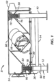
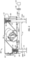
- FIGS. 1 and 2 illustrate one example of a vibratory screen separator that does not form part of the present invention.
- the separator 5 includes a base 10 having four legs 12 and supporting members 14. Mounted on the four legs 12 are resilient mounts 16. Each mount 16 includes a spring 18, a base 20 on each leg 12 and a socket 22 on the separator to receive each spring 18. Positioned on the base 10 by the resilient mounts 16 is a separator frame or basket 24.
- the basket 24, includes sidewalls 26 and 28 and a back wall 30.The front side, opposite to the back wall 30, may be left open.
- the basket 24 is of sufficient structure to withstand the vibrational loads imposed on the basket 24 in operation. Extending across the interior of the basket 24 between the sidewalls 26 and 28 is a structural tube 32 which may be positioned at roughly the center of mass for further structural strength.
- a channel 34 Located about the sidewalls 26 and 28 and the back wall 30 is a channel 34. Located above the channel 34 on the sidewalls 26 and 28 are stops 38 and 40. The stops cooperate with the channel 34 through its extent along the sidewalls 26 and 28 to form a screen mounting in a first plane. A screen 42 having a screen frame 44 and screen cloth 46 is illustrated positioned in the screen mounting. Resilient members 48 are positioned on the underside of the stops 38 and 40 to help locate, seat and seal the screen frame 44. Obviously, multiple screens 42 may be employed in any one separator.
- a sump 50 is located below the screen mounting to receive material passed through the screen 42.
- An inlet 52 is positioned at the back wall 30 above the screen mounting.
- An outlet 54 for material passed through the screen 42 receives material from the sump 50 for discharge. Material not passing through the screen 42 is discharged off the end of the screen 42 and suitably collected.
- the flow across the screen plane from the inlet 52 toward the outlet 54 defines a linear direction of material travel. Attached to the sides of the basket 24 and specifically to each sidewall 26 and 28 are two rotary eccentric vibrators 56 and 58.
- sump 50 maybe integrally connected to basket 24.
- sump 50 may be referred to as a vibrating sump.
- sump 50 may be separate from basket 24, a stationary sump.
- a pressure differential device may be provided to create a pressure differential between the vapor space above screen 42 and the vapor space between screen 42 and sump 50.
- the pressure differential device may be located internal to sump 50, such as an air pump (not shown) or the pressure differential device may be located external to sump 50, such as a vacuum system (not shown). Whether internal or external to sump 50,the pressure differential device may cause vapor to flow from the vapor space between screen 42 and sump 50 to a point external to sump 50, such as through outlet 54 or other conduits forming an outlet from sump 50.
- the pressure differential device may include pumps, blowers, aspirators, ejectors, and the like, and combinations thereof.
- the pressure differential may be created by one or more of a positive displacement pump, a momentum transfer pump, or an entrapment pump.
- Pumps useful in creating the pressure differential or vacuum include reciprocating pumps, centrifugal pumps, vacuum pumps, pneumatic pumps, electric pumps, air pumps, piston pumps, rotary piston pumps, rotary vane pumps, screw pumps, scroll pumps, liquid ring pumps, external vane pumps, Wankel pumps, Toepler pumps, and Venturi vacuum pumps, among others.
- Blowers useful in creating the pressure differential may include booster pumps, a rotary lobe blower (such as a ROOTS TM blower), and vacuum blowers.
- Useful ejectors and aspirators may include steam ejectors, water aspirators, or ejectors and aspirators utilizing other motive fluids. In some examples, drilling fluid is used asthe motive fluid for an ejector or an aspirator.
- the pressure differential may be pulsed, toggled, or intermittently interrupted. Toggling or pulsing of the pressure differential, as used herein, refers to the changing of the pressure differential from static (a zero pressuredifferential across the screen) to at least a partial vacuum below the screen.
- the pressure differential may be toggled from static to at least a partial vacuum or the pressure differential across a screen may be toggled or pulsed from static to a full vacuum below the screen.
- the pressure differential may be toggled from static to a pressure differential in the range from about -0.1 to about -1.0 bar, as given by a quantity defined as a pressure below the screen minus a pressure above the screen or the pressure differential may be toggled from static to a pressure differential in the range from about -0.2 to about -0.7 bar, as given by a quantity defined as a pressure below the screen minus a pressure above the screen; from static to a pressure differential in the range from about -0.2 to about -0.7 bar; and from about - 0.3 bar to about -0.6 bar .By toggling the pressure between vacuum and static, conveyance of solids acrossthe screen may proceed unhindered, thereby avoiding solids accumulating or sticking on the screen, and thus not preventing fluid flow through the screen.
- Pulsing or toggling the pressure differential between static and vacuum below the screen may be effectuated by a valve disposed between the pressure differential device (pumps, ejectors, etc., as described above) and the screen. Manipulating the valve by opening and/or closing the valve, at least partially, may disrupt the flow of vapor from the sump, thereby affecting the pressure differential.
- the toggling device such as a valve, may be disposed between a vacuum generating device or system and the sump locatedunder one or more of the screens.
- Valves useful for toggling the pressure differential may include rotary valves, ball valves, globe valves, needle valves, butterfly valves, gate valves, plug valves, diaphragm valves, and piston valves, among others.
- the valves may be manually operated or may be remotely actuated valves .
- the separator in the pulsed-vacuum assisted screening device disclosed herein, includes two or more screens. Sumps are located under the screens such that a pressure differential is provided across the two or more shaker screens. In embodiments of the invention, the same or different pressure differentials may be provided across zoned shaker screens.
- FIG. 3 illustrates an embodiment of a pulsed-vacuum assisted screening device having separate pressure zones according to the present invention, where like numerals represent like parts.
- Separator 60 includes two or more screens (not shown), correspondingly located above two or more sumps 50 (i.e., 50A and 50B as illustrated). For example, where separator 60 has four screens in series, sump 50A is located proximate inlet 52 under the first two screens. Sump 50B is located proximate outlet 54B, under the last two screens (where first and last corresponds to the direction of flow from inlet 52 to outlet 54B). Sump 50A thus creates an independent zone from sump 50B, allowing for operations of the two zones at the same or different pressure differentials.
- One or more devices are provided to create a pressure differential across either or both sets of screens. The pressure differential across the screens, in either zone, may be manipulated to provide additional capacity or to enhance the liquid recovery, resulting in a dryer cutting fraction.
- outlet 54A is provided to discharge material passing through the first two screens into sump 50A.
- one or more pressure differential devices are provided to create a pressure differential between the vapor space above the screens and the vapor space between the screens and sumps 50A, 50B.
- the pressure differential devices are located external to sumps 50A, 50B.
- the pressure differential devices cause vapor to flow from the vapor space betweenthe screen and sump 50A, 50B to a point external to each sump 50A, 50B, such as through outlets 54A, 54B, or other conduits forming an outlet from sumps 50A, 50B.
- Outlet 54A is used as a liquid outlet, discharging the drilling fluid and other solids passing through screens.
- An outlet 56A is provided to convey vapor from sump 50Ato create the desired pressure differential.
- Outlet 56A in some embodiments, may be connected to a lobe pump 58 or to one or more vacuum generating devices as described above. The vapor discharge from vacuum generating device 58 is then be vented or further processed, such as through a vapor recovery or incineration system 59.
- FIG. 4 illustrates another example t of a pulsed-vacuum assisted screening device that does not form part of the present invention.
- the separator may include a base, legs, supporting members, and other component parts as previously illustrated for mounting separator frame 74.
- Separator frame 74 may include sidewalls 76, 78 and a back wall 80.
- the front side 81, opposite to the back wall 80, may be left open.
- the frame 74 may be of sufficientstructure to withstand the vibrational loads imposed on the frame 74.
- Extending across the interior of the frame 74 between the sidewalls 76, 78 may be a structural tube 82 which may be positioned at roughly the center of mass, for further structural strength.
- a channel Located about the sidewalls 76 and 78 and the back wall 80 is a channel (not shown). Located above the channel on the sidewalls 76 and 78 are stops 88 and 90. The stops cooperate with the channel (not shown) through its extent along the sidewalls 76 and 78 to form a screen mounting in a first plane. A screen 92 is illustrated positioned in the screen mounting. Multiple screens 92 may be employed in any one separator.
- One or more shaker screens 92 may be installed in, or secured to, the shale shaker frame 74 with a wedge block 94.
- the screen 92 is placed on a support rail (not shown) and positioned underneath a stationary wedge guide 88 (stop 88).
- the wedge block 90 (stop 90) is then pounded into position so as to secure the screens 92 to frame 74.
- the wedge block 90 may also include a hammer surface 94 to aid in installation (as by pounding on surface 94a) and removal (as by pounding on surface 94b).
- An inlet (not shown) may be located proximate back wall 80.
- the solids may then travel on top of the screens toward front side 81.
- the separator has four screens 92.
- the drilling mud may be deposited on the first screen 92A.
- a sump 96 may be provided under the first two screens 92A, 92B. As illustrated, sump 96 may be integrally formed with frame 74. One or more pressure differential devices , as described above, may be provided to generate a pressure differential across screens 92A, 92B. An outlet 98 may be provided to convey vapor from sump 96 to create the desired pressure differential.
- a shaker 100 may include a basket 102, shaker screen 104, and sump 106, as described above.
- a drilling fluid 108 to be separated such as a mixture of drilling mud and drill cuttings, may be fedto inlet end A of the shaker 100. Drill cuttings separated from drilling fluid 108 may be recovered at outlet end B. The drilling mud 110 separated from the drill cuttings may be collected in sump 106.
- the vapor space 112 of sump 106 may be fluidly connected via flow line 113 to a valve 114 and a pressure differential device 116, as described above.
- vacuum system inlet 118 may be disposed vertically downward, may include a cover 120, such as to direct fluid away from inlet 118, or may include other safety devices to prevent fluid from entering the vapor system.
- Vapors recovered via pressure differential device 116 may be flared, vented, or recovered via flow line 122. Fluids 110 may be recovered from sump 106 via flow line 124, and in some examples may be directed to a mud tank for further processing and/or recycled to the mud system.
- the fluid 110 collecting in sump 106 during the separations may be degassed or partially degassed by the vacuum or partial vacuum generated by pressure differential device 116. Operation of pressure differential device 116 results in at least a partial vacuum in sump 106 and may provide a driving force for gases that may be dissolved or entrained in the fluid 110 to be separated therefrom.
- vent 126 may be provided to aid in pressure control of sump 106 or to provide means to avoid under-pressure of sump 106, where vent 126 may include pressure relief valves and other devices known in the art to provide flow in limited circumstances.
- a shaker 200 includes a basket 202, shaker screen 204, and sump 206, as described above.
- a drilling fluid 208 to be separated such as a mixture of drilling mud and drill cuttings, is fed to inlet end A of the shaker 200. Drill cuttings separated from drilling fluid 208 are recovered at outlet end B. The drilling mud 210 separated from the drill cuttings is collected in sump 206.
- sump 206 is fluidly connected via flow line 213 to a degassing chamber 212, valve 214, and a pressure differential device 216, as described above.
- Generation of the intermittent pressure differential across screen 204 results in both liquids and vapors being pulled from sump 206 to degassing chamber 212.
- the vapors collecting in degassing chamber 212 are recovered via flow line 217, and are vented via flow line 222.
- Fluids 210 collecting in degassing chamber 212 are recovered via flow line 224, and in some embodiments may be directed to a mud tank for further processing and/or recycle to the mud system.
- a vent 226 is provided to aid in pressure control of degassing chamber 212, where vent 226 may include pressure relief valves and other devices known in the art to provide flow in limited circumstances.
- the fluid 210 collecting in degassing chamber 212 during the separation process is degassed or partially degassed by the vacuum or partial vacuum generated by the pressure differential device 216. Operation of pressure differential device 216 results in at least a partial vacuum in degassing chamber 212, and provides a driving force for gases that may be dissolved or entrained to be separated from the fluid 210. Such degassing allows for a simplified mud tank system, where vents and other degassing equipment may not be necessary.
- shaker systems described herein include a pressure differential device or vacuum generating device to generate an intermittent pressure differential across a shaker screen.
- the vacuum generated by the pressure differential device provides an additional driving force for separating fluids from drill cuttings, and additionally removes vapors and entrained gases from the filtered drilling fluid.
- vibratory separator 500 includes a housing 502, a drilling fluid inlet end504, an outlet end 506, and a plurality shaker screens 508.
- the plurality of shaker screens 508 are assembled in a multi-tier configuration. By vertically stacking multiple shaker screens 508, the footprint of vibratory separator 500 is decreased, thereby providing equivalent separating potential while requiring less space.
- the size of the apertures in the screens may be varied according to each tier.
- the screen assembly apertures may be substantially greater in size than the apertures of lower screen assemblies.
- a series of flowback pans 522 may be located under shaker screens 508. Flowback pans 522 may be directed to deposit drilling fluid into a sump 510, thereby allowing drilling fluid to be substantially cleaner at each level of processing.
- vibratory separator 500 also includes a fume hood/outlet 516 connected to housing 502.
- the fume hood/outlet 516 may include a vacuum system that extracts vapors into the vent hood/outlet 516.
- the drilling fluid enters vibratory shaker 500 through inlet end 504
- the drilling fluid falls onto shaker screen 508 and is conveyed from inlet end 504 to outlet end 506 using vibratory motion and pulse-assisted screening devices as described above.
- vapors including potentially hazardous gases, for example, hydrogen sulfide ("H2S"), entrained in the drilling fluid maybe present.
- H2S hydrogen sulfide
- fume hood/outlet 516 is configured to extract vapors from the drilling fluid as it flows across the shaker screens 508. As vapors and fumes are released in a generally upward direction from the drilling fluid, fume hood/outlet 516 may pull the vapors and fumes inward, thereby trapping the potentially hazardous fumes and/or vapors.
- fume hood/outlet 516 may pull the vapors and fumes inward, thereby trapping the potentially hazardous fumes and/or vapors.
- fume hood/outlet 516 may be turned on during any step of the separation process including during normal separation, during cleaning, or substantially continuously.
- examples including fume hood/outlets 516 may provide for a vibratory separator 500 that is substantially enclosed, thereby preventing the escape of hazardous materials and/or vapors into the drilling work space.
- vibratory separator 500 may further include one or more pressure differential devices (not shown) to create a pressure differential between a vapor space 512 above and between the screens 508 and sump 510.
- the pressure differential devices may be located internal to sump 510.
- the pressure differential devices may be located external to sump 510. Whether internal or external to sump 510, the pressure differential devices (not shown) may cause vapor to flow from the vapor space between the screens 508 and sump 510 to a point external to sump 510, such as through outlets 54A, 54B (shown in FIG. 3 ).
- Fume hood/outlet 516 may be in fluid connection with outlets 54A, 54B to pull vapors that flow through such outlets 54A, 54B, thereby trapping the potentially hazardous fumes and/or vapors. Vapors and fumes trapped in fume hood/outlet 516 may be treated and/or safely removed from vibratory shaker 500 thereafter.
- vibratory separator 500 may include one or more pressure differential devices (not shown) to create a pressure differential between a vapor space 512 above the screens 508 and flowback pans 522.
- the pressure differential devices may be located internal to flowback pans 522.
- the pressure differential devices may be located external to flowback pans 522. Whether internal or external to flowback pans 522, the pressure differential devices (not shown) may cause vapor to flow from the vapor space between the screens 508 and flowback pans 522 to a point external to flowback pans 522, such as through outlets 54A, 54B (shown in FIG. 3 ).
- Fume hood/outlet 516 may be in fluid connection with outlets 54A, 54B to pull vapors that flow through such outlets 54A, 54B, thereby trapping the potentially hazardous fumes and/or vapors. Vapors and fumes trapped in fume hood/outlet 516 may be treated and/or safely removed from vibratory shaker 500 thereafter.
- the drilling fluid may be directed to a containment area where the drilling fluid may be degassed to remove remaining entrained gases.
- Degassing the drilling fluid may be performed by any method known in the art.
- mechanical degassers and aeration devices may be used.
- a mechanical degasser may exert a centrifugal force on the drilling fluid.
- the centrifugal force of the mechanicaldegasser multiplies the force acting on the entrained gas (e.g., H2S) to increase buoyancy of the gas, thereby releasing entrained gas from the drilling fluid.
- the increase in buoyancy of the gas accelerates the bubble-rise velocity of the gas velocity, and as the gas bubbles rise toward the surface, they escape the drilling fluid.
- any device known in the art that exerts a centrifugal force on the fluid, thereby reducing the amount of entrained or dissolved gases in the process fluid, may be used in place of a mechanical degasser.
- embodiments disclosed herein may provide shakers having increased fluid capacity, increased fluid flow-through rates across the screens, and/or improved fluid removal efficiencies. Also, advantageously, embodiments disclosed herein may provide shakers with reduced hazardous vapors in vapor spaces. Finally, embodiments disclosed herein may provide shakers that more efficiently separate entrained gases from drilling fluids.
Landscapes
- Chemical Kinetics & Catalysis (AREA)
- Chemical & Material Sciences (AREA)
- Engineering & Computer Science (AREA)
- Geology (AREA)
- Mining & Mineral Resources (AREA)
- Life Sciences & Earth Sciences (AREA)
- General Life Sciences & Earth Sciences (AREA)
- Fluid Mechanics (AREA)
- Environmental & Geological Engineering (AREA)
- Physics & Mathematics (AREA)
- Mechanical Engineering (AREA)
- Geochemistry & Mineralogy (AREA)
- Vaporization, Distillation, Condensation, Sublimation, And Cold Traps (AREA)
- Separation Of Solids By Using Liquids Or Pneumatic Power (AREA)
- Fluid-Damping Devices (AREA)
- Physical Water Treatments (AREA)
- Cyclones (AREA)
- Mechanical Treatment Of Semiconductor (AREA)
- Transition And Organic Metals Composition Catalysts For Addition Polymerization (AREA)
- Carbon And Carbon Compounds (AREA)
- Degasification And Air Bubble Elimination (AREA)
Description
- Embodiments disclosed herein relate generally to shale shakers and screens for shale shakers. Specifically, embodiments disclosed herein relate to a shale shaker having pulse-vacuum assisted screening. Additionally, embodiments disclosed herein relate to methods and apparatus for removing entrained gases from a slurry.
- Oilfield drilling fluid, often called "mud," serves multiple purposes in the industry. Among its many functions, the drilling mud acts as a lubricant to cool rotary drill bits and facilitate faster cutting rates. The mud is mixed at the surface and pumped downhole through a bore of the drill string to the drill bit where it exits through various nozzles and ports, lubricating and cooling the drill bit. After exiting through the nozzles, the "spent" fluid returns to the surface through an annulus formed between the drill string and the drilled wellbore.
- Furthermore, drilling mud provides a column of hydrostatic pressure, or head, to prevent "blow out" of the well being drilled. This hydrostatic pressure offsets formation pressures thereby preventing fluids from blowing out if pressurized deposits in the formation are breeched. Two factors contributing to the hydrostatic pressure of the drilling mud column are the height (or depth) of the column (i.e., the vertical distance from the surface to the bottom of the wellbore) and the density (or its inverse, specific gravity) of the fluid used. Various weighting and lubrication agents are mixed into the drilling mud to obtain the right mixture for the type and construction of the formation to be drilled. Increasing the amount of weighting agent solute dissolved in the mud base will generally create a heavier drilling mud. Drilling mud that is too light may not protect the formation from blow outs, and drilling mud that is too heavy may over invade the formation. Therefore, much time and consideration is spent to ensure the mud mixture is optimal. Because the mud evaluation and mixture process is time consuming and expensive, drillers and service companies prefer to reclaim the returned drilling mud and recycle it for continued use.
- Another significant purpose of the drilling mud is to carry the cuttings away from the drill bit to the surface. As a drill bit pulverizes or scrapes the rock formation at the bottom of the borehole, small pieces of solid material are left behind. The drilling fluid exiting the nozzles at the bit stir up and carry the solid particles of rock and formation to the surface within the annulus between the drillstring and the borehole. Therefore, the fluid exiting the borehole from the annulus is a slurry of formation cuttings in drilling mud, and the cutting particulates must be removed before the mud can be recycled.
- One type of apparatus used to remove cuttings and other solid particulates from drilling mud is commonly referred to in the industry as a "shale shaker." A shale shaker, also known as a vibratory separator, is a vibrating sieve-like table upon which returning used drilling mud is deposited and through which substantially cleaner drilling mud emerges. Typically, the shale shaker is an angled table with a generally perforated filter screen bottom. Returning drilling mud is deposited at the top of the shale shaker. As the drilling mud travels down the incline toward the lower end, the fluid falls through the perforations to a reservoir below thereby leaving the solid particulate material behind. The combination of the angle of inclination with the vibrating action of the shale shaker table enables the solid particles left behind to flow until they fall off the lower end of the shaker table. The above described apparatus is illustrative of one type of shale shaker known to those of ordinary skill in the art. In alternate shale shakers, the top edge of the shaker may be relatively closer to the ground than the lower end. In such shale shakers, the angle of inclination may require the movement of particulates in a generally upward direction. In still other shale shakers, the table may not be angled, thus the vibrating action of the shaker alone may enable particle/fluid separation. Regardless, table inclination and/or design variations of existing shale shakers should not be considered a limitation of the present disclosure.
- Preferably, the amount of vibration and the angle of inclination of the shale shaker table are adjustable to accommodate various drilling mud flow rates and particulate percentages in the drilling mud. After the fluid passes through the perforated bottom of the shale shaker, it may either return to service in the borehole immediately, be stored for measurement and evaluation, or pass through an additional piece of equipment (e.g., a drying shaker, a centrifuge, or a smaller sized shale shaker) to remove smaller cuttings and/or particulate matter.
- Screens used with shale shakers are typically emplaced in a generally horizontal fashion on a generally horizontal bed or support within a basket in the shaker. The screens themselves may be flat or nearly flat, corrugated, depressed, or contain raised surfaces. The basket in which the screens are mounted may be inclined towards a discharge end of the shale shaker. The shale shaker imparts a rapidly reciprocating motion to the basket and hence the screens. Material from which particles are to be separated is poured onto a back end of the vibrating screen, flowing toward the discharge end of the basket. Large particles that are unable to move through the screen remain on top of the screen and move toward the discharge end of the basket where they are collected. The smaller particles and fluid flow through the screen and collect in a bed, receptacle, sump, or pan beneath the screen.
- In some shale shakers a fine screen cloth is used with the vibrating screen. The screen may have two or more overlaying layers of screen cloth or mesh. Layers of cloth or mesh may be bonded together and placed over a support, supports, or a perforated or apertured plate. The frame of the vibrating screen is resiliently suspended or mounted upon a support and is caused to vibrate by a vibrating mechanism (e.g., an unbalanced weight on a rotating shaft connected to the frame). Each screen may be vibrated by vibratory equipment to create a flow of trapped solids on top surfaces of the screen for removal and disposal of solids. The fineness or coarseness of the mesh of a screen may vary depending upon mud flow rate and the size of the solids to be removed.
- While there are numerous styles and sizes of filter screens, they generally follow similar design. Typically, filter screens include a perforated plate base upon which a wire mesh, or other perforated filter overlay, is positioned. The perforated plate base generally provides structural support and allows the passage of fluids therethrough, while the wire mesh overlay defines the largest solid particle capable of passing therethrough. While many perforated plate bases are generally flat or slightly curved in shape, it should be understood that perforated plate bases having a plurality of corrugated or pyramid-shaped channels extending thereacross may be used instead. In theory, the pyramid-shaped channels provide additional surface area for the fluid-solid separation process to take place, and act to guide solids along their length toward the end of the shale shaker from where they are disposed.
- The separation of drilling fluid and other solids from drill cuttings using a screen shaker is often incomplete, resulting in wet drill cuttings. As described above, the drilling mud is introduced to the top of the screen and allowed to flow downward through the screen by gravity alone. Often, additional equipment, such as additional screen separators, hydrocyclones, dryers, drying shakers, centrifuges, hydrocyclone shakers, thermal desorption systems, and other equipment, are used to further dry the cuttings and recover drilling fluid. For example, cuttings from a shale shaker may fall onto a rotary vacuum dryer, where the cuttings travel on a circumferentially rotating screen. Air may be used to strip drilling fluid off the cuttings and into the screen, such as by pulling a vacuum from the interior of the rotating screen (for example, the ROTAVAC™ Rotary Vacuum Dryer fluid recovery and cuttings drying system, available from Halliburton).
- It is desired to improve the rate and efficiency at which shakers remove liquid from cuttings or other solids. To enhance the gravity-driven separation as described above, it is known that increasing the head on the shaker can increase the throughput of fluids through the screen. Increasing the pressure differential through the screen will likewise increase the fluid capacity of the shaker.
- One example of a shaker with increased pressure differential is disclosed by
Hensley et al. in U.S. Patent Application Publication No. 2005/183994 A1 . Hensley et al. discloses an integrated, transportable cutting treatment system, where a pressure differential is developed across the screens to increase the flow rate of drilling mud through the screens. Hensley et al. uses an air pump to develop a vacuum beneath the screens to draw mud through the screens. However, applying a continuous vacuum beneath a screen to draw fluid through the screen may result in solids sticking to thescreen, hindering the conveyance of solids off the end of the shaker as needed, thereby preventing fluids from being filtered through the screen.US2005/0082236 discloses a system and method for separating components of a slurry, comprising providing a slurry to a top of a shale shaker comprising 3 screens and 3 corresponding sumps and applying pressure differential across each screen via each sump. - There exists a continuing desire for shakers having increased fluid capacity, increased fluid flow-through rates across the screens, and/or improved fluid removal efficiencies. Accordingly, there exists a need for a shaker with increased pressure differential. Preferably, the means used to increase the pressure differential do not substantially hinder the flow of solids across the screen deck. Additionally, there exists a need for a shaker for removing entrained gases from the recovered drilling fluid.
- The present invention provides a method as defined in claim 1 and a system for separating drill cuttings and drilling fluid within a shaker as defined in claim 3.
- The accompanying drawings illustrate presently exemplary embodiments of the disclosure, and together with the general description given above and the detailed description of the exemplary embodiments given below, serve to explain, by way of example, the principles of the disclosure.
-
FIG. 1 is a side view of a vibratory screen separator in an examples that does not form part of the present invention. -
FIG. 2 is a cross-sectional view of the screen separator ofFIG.1 . -
FIG. 3 is a side view of a vibratory screen separator useful in embodiments of the present invention, where the separator may be fluidly attached to a vacuum system. -
FIG. 4 is a perspective view of a vibratory screen separator frame and sump in an example that does not form part of the present invention. -
FIG. 5 is a simplified flow diagram for embodiments of a system for generating a pressure differential across a screen and degassing a fluid according to an example that does not form part of the present invention. -
FIG. 6 is a simplified flow diagram for embodiments of a system for generating a pressure differential across a screen and degassing a fluid according to the present invention. -
FIG. 7 is a perspective view of a vibratory screen separator having a vacuum fume extraction device in accordance with an example that does not form part of the present invention. - Embodiments disclosed herein relate to a method for separating components of a slurry. As used herein, a slurry refers to a mixture of drilling fluid and drill cuttings. A slurry is separated using a screen separator having a pressure differential across the screen. Embodiments disclosed herein also relate to a system for separating components of a slurry. The system includes a vibratory screen separator and a pressure differential device or a vacuum generating device. The pressure differential device additionally provides a driving force to degas the recovered drilling fluid.
-
FIGS. 1 and2 illustrate one example of a vibratory screen separator that does not form part of the present invention. Theseparator 5 includes a base 10 having fourlegs 12 and supportingmembers 14. Mounted on the fourlegs 12 areresilient mounts 16. Eachmount 16 includes aspring 18, abase 20 on eachleg 12 and asocket 22 on the separator to receive eachspring 18. Positioned on thebase 10 by the resilient mounts 16 is a separator frame orbasket 24. Thebasket 24, includessidewalls back wall 30, may be left open. Thebasket 24 is of sufficient structure to withstand the vibrational loads imposed on thebasket 24 in operation. Extending across the interior of thebasket 24 between the sidewalls 26 and 28 is astructural tube 32 which may be positioned at roughly the center of mass for further structural strength. - Located about the
sidewalls back wall 30 is achannel 34. Located above thechannel 34 on thesidewalls stops channel 34 through its extent along thesidewalls screen 42 having ascreen frame 44 andscreen cloth 46 is illustrated positioned in the screen mounting.Resilient members 48 are positioned on the underside of thestops screen frame 44. Obviously,multiple screens 42 may be employed in any one separator. - A
sump 50 is located below the screen mounting to receive material passed through thescreen 42. Aninlet 52 is positioned at theback wall 30 above the screen mounting. Anoutlet 54 for material passed through thescreen 42 receives material from thesump 50 for discharge. Material not passing through thescreen 42 is discharged off the end of thescreen 42 and suitably collected. The flow across the screen plane from theinlet 52 toward theoutlet 54 defines a linear direction of material travel. Attached to the sides of thebasket 24 and specifically to eachsidewall eccentric vibrators - As illustrated in
FIGS. 1 and2 ,sump 50 maybe integrally connected tobasket 24. Thus,sump 50 may be referred to as a vibrating sump. In other examples,sump 50 may be separate frombasket 24, a stationary sump. - A pressure differential device (not shown) may be provided to create a pressure differential between the vapor space above
screen 42 and the vapor space betweenscreen 42 andsump 50. The pressure differential device may be located internal tosump 50, such as an air pump (not shown) or the pressure differential device may be located external tosump 50, such as a vacuum system (not shown). Whether internal or external tosump 50,the pressure differential device may cause vapor to flow from the vapor space betweenscreen 42 andsump 50 to a point external tosump 50, such as throughoutlet 54 or other conduits forming an outlet fromsump 50. - The pressure differential device may include pumps, blowers, aspirators, ejectors, and the like, and combinations thereof. The pressure differential may be created by one or more of a positive displacement pump, a momentum transfer pump, or an entrapment pump.
- Pumps useful in creating the pressure differential or vacuum in some embodiments include reciprocating pumps, centrifugal pumps, vacuum pumps, pneumatic pumps, electric pumps, air pumps, piston pumps, rotary piston pumps, rotary vane pumps, screw pumps, scroll pumps, liquid ring pumps, external vane pumps, Wankel pumps, Toepler pumps, and Venturi vacuum pumps, among others. Blowers useful in creating the pressure differential may include booster pumps, a rotary lobe blower (such as a ROOTS™ blower), and vacuum blowers. Useful ejectors and aspirators may include steam ejectors, water aspirators, or ejectors and aspirators utilizing other motive fluids. In some examples, drilling fluid is used asthe motive fluid for an ejector or an aspirator.
- The pressure differential may be pulsed, toggled, or intermittently interrupted. Toggling or pulsing of the pressure differential, as used herein, refers to the changing of the pressure differential from static (a zero pressuredifferential across the screen) to at least a partial vacuum below the screen. The pressure differential may be toggled from static to at least a partial vacuum or the pressure differential across a screen may be toggled or pulsed from static to a full vacuum below the screen. The pressure differential may be toggled from static to a pressure differential in the range from about -0.1 to about -1.0 bar, as given by a quantity defined as a pressure below the screen minus a pressure above the screen or the pressure differential may be toggled from static to a pressure differential in the range from about -0.2 to about -0.7 bar, as given by a quantity defined as a pressure below the screen minus a pressure above the screen; from static to a pressure differential in the range from about -0.2 to about -0.7 bar; and from about - 0.3 bar to about -0.6 bar .By toggling the pressure between vacuum and static, conveyance of solids acrossthe screen may proceed unhindered, thereby avoiding solids accumulating or sticking on the screen, and thus not preventing fluid flow through the screen.
- Pulsing or toggling the pressure differential between static and vacuum below the screen, may be effectuated by a valve disposed between the pressure differential device (pumps, ejectors, etc., as described above) and the screen. Manipulating the valve by opening and/or closing the valve, at least partially, may disrupt the flow of vapor from the sump, thereby affecting the pressure differential. Alternatively, the toggling device, such as a valve, may be disposed between a vacuum generating device or system and the sump locatedunder one or more of the screens.
- Valves useful for toggling the pressure differential may include rotary valves, ball valves, globe valves, needle valves, butterfly valves, gate valves, plug valves, diaphragm valves, and piston valves, among others. The valves may be manually operated or may be remotely actuated valves .
- According to embodiments of the invention, in the pulsed-vacuum assisted screening device disclosed herein, the separator includes two or more screens. Sumps are located under the screens such that a pressure differential is provided across the two or more shaker screens. In embodiments of the invention, the same or different pressure differentials may be provided across zoned shaker screens.
-
FIG. 3 illustrates an embodiment of a pulsed-vacuum assisted screening device having separate pressure zones according to the present invention, where like numerals represent like parts.Separator 60 includes two or more screens (not shown), correspondingly located above two or more sumps 50 (i.e., 50A and 50B as illustrated). For example, whereseparator 60 has four screens in series,sump 50A is locatedproximate inlet 52 under the first two screens.Sump 50B is locatedproximate outlet 54B, under the last two screens (where first and last corresponds to the direction of flow frominlet 52 tooutlet 54B).Sump 50A thus creates an independent zone fromsump 50B, allowing for operations of the two zones at the same or different pressure differentials. One or more devices are provided to create a pressure differential across either or both sets of screens. The pressure differential across the screens, in either zone, may be manipulated to provide additional capacity or to enhance the liquid recovery, resulting in a dryer cutting fraction. - To maintain separate pressure differentials,
sumps outlet 54A is provided to discharge material passing through the first two screens intosump 50A. - As described above, one or more pressure differential devices are provided to create a pressure differential between the vapor space above the screens and the vapor space between the screens and
sumps sumps sump sump outlets sumps -
Outlet 54A is used as a liquid outlet, discharging the drilling fluid and other solids passing through screens. Anoutlet 56A is provided to convey vapor from sump 50Ato create the desired pressure differential.Outlet 56A, in some embodiments, may be connected to alobe pump 58 or to one or more vacuum generating devices as described above. The vapor discharge fromvacuum generating device 58 is then be vented or further processed, such as through a vapor recovery orincineration system 59. -
FIG. 4 illustrates another example t of a pulsed-vacuum assisted screening device that does not form part of the present invention. The separator may include a base, legs, supporting members, and other component parts as previously illustrated for mountingseparator frame 74.Separator frame 74 may includesidewalls back wall 80. Thefront side 81, opposite to theback wall 80, may be left open. Theframe 74 may be of sufficientstructure to withstand the vibrational loads imposed on theframe 74. Extending across the interior of theframe 74 between the sidewalls 76, 78 may be astructural tube 82 which may be positioned at roughly the center of mass, for further structural strength. - Located about the
sidewalls back wall 80 is a channel (not shown). Located above the channel on thesidewalls stops sidewalls screen 92 is illustrated positioned in the screen mounting.Multiple screens 92 may be employed in any one separator. - One or
more shaker screens 92 may be installed in, or secured to, theshale shaker frame 74 with a wedge block 94. Thescreen 92 is placed on a support rail (not shown) and positioned underneath a stationary wedge guide 88 (stop 88). The wedge block 90 (stop 90) is then pounded into position so as to secure thescreens 92 to frame 74. One of ordinary skill in the art will appreciate that the operator often chooses to use a combination of a hammer and a suitable piece of wood in contact with thewedge block 90 to deliver sufficient force to fully tighten thewedge block 90. As shown inFIG. 4 , thewedge block 90 may also include a hammer surface 94 to aid in installation (as by pounding on surface 94a) and removal (as by pounding on surface 94b). - An inlet (not shown) may be located
proximate back wall 80. The solids may then travel on top of the screens towardfront side 81. As illustrated, the separator has fourscreens 92. The drilling mud may be deposited on thefirst screen 92A. - A
sump 96 may be provided under the first twoscreens sump 96 may be integrally formed withframe 74. One or more pressure differential devices , as described above, may be provided to generate a pressure differential acrossscreens outlet 98 may be provided to convey vapor fromsump 96 to create the desired pressure differential. - Referring now to
FIG. 5 , an example of a simplified flow diagram for a system for generating a pressure differential across a screen and degassing a fluid, that does not form part of the present invention, is illustrated. Ashaker 100 may include abasket 102,shaker screen 104, andsump 106, as described above. Adrilling fluid 108 to be separated, such as a mixture of drilling mud and drill cuttings, may be fedto inlet end A of theshaker 100. Drill cuttings separated from drilling fluid 108 may be recovered at outlet end B. Thedrilling mud 110 separated from the drill cuttings may be collected insump 106. - To generate the desired intermittent pressure differential across
screen 104, thevapor space 112 ofsump 106 may be fluidly connected viaflow line 113 to a valve 114 and a pressuredifferential device 116, as described above. To prevent liquids from enteringflow line 113 and pressuredifferential device 116,vacuum system inlet 118 may be disposed vertically downward, may include acover 120, such as to direct fluid away frominlet 118, or may include other safety devices to prevent fluid from entering the vapor system. - Vapors recovered via pressure
differential device 116 may be flared, vented, or recovered viaflow line 122.Fluids 110 may be recovered fromsump 106 viaflow line 124, and in some examples may be directed to a mud tank for further
processing and/or recycled to the mud system. - In the example illustrated in
FIG. 5 , the fluid 110 collecting insump 106 during the separations may be degassed or partially degassed by the vacuum or partial vacuum generated by pressuredifferential device 116. Operation of pressuredifferential device 116 results in at least a partial vacuum insump 106 and may provide a driving force for gases that may be dissolved or entrained in the fluid 110 to be separated therefrom. - If necessary, a
vent 126 may be provided to aid in pressure control ofsump 106 or to provide means to avoid under-pressure ofsump 106, wherevent 126 may include pressure relief valves and other devices known in the art to provide flow in limited circumstances. - Referring now to
FIG. 6 , a simplified flow diagram for embodiments of a system for generating a pressure differential across a screen and degassing the recovered fluid, according to the present invention, is illustrated. Ashaker 200 includes abasket 202,shaker screen 204, andsump 206, as described above. Adrilling fluid 208 to be separated, such as a mixture of drilling mud and drill cuttings, is fed to inlet end A of theshaker 200. Drill cuttings separated from drilling fluid 208 are recovered at outlet end B. Thedrilling mud 210 separated from the drill cuttings is collected insump 206. - To generate the desired intermittent pressure differential across
screen 204,sump 206 is fluidly connected viaflow line 213 to adegassing chamber 212,valve 214, and a pressuredifferential device 216, as described above. Generation of the intermittent pressure differential acrossscreen 204 results in both liquids and vapors being pulled fromsump 206 to degassingchamber 212. The vapors collecting in degassingchamber 212 are recovered viaflow line 217, and are vented via flow line 222.Fluids 210 collecting in degassingchamber 212 are recovered viaflow line 224, and in some embodiments may be directed to a mud tank for further processing and/or recycle to the mud system. Avent 226 is provided to aid in pressure control of degassingchamber 212, wherevent 226 may include pressure relief valves and other devices known in the art to provide flow in limited circumstances. - The fluid 210 collecting in degassing
chamber 212 during the separation process is degassed or partially degassed by the vacuum or partial vacuum generated by the pressuredifferential device 216. Operation of pressuredifferential device 216 results in at least a partial vacuum in degassingchamber 212, and provides a driving force for gases that may be dissolved or entrained to be separated from thefluid 210. Such degassing allows for a simplified mud tank system, where vents and other degassing equipment may not be necessary. - As described above, shaker systems described herein include a pressure differential device or vacuum generating device to generate an intermittent pressure differential across a shaker screen. The vacuum generated by the pressure differential device provides an additional driving force for separating fluids from drill cuttings, and additionally removes vapors and entrained gases from the filtered drilling fluid.
- Referring now to
FIG. 7 , a perspective view of avibratory separator 500 in accordance with an example that does not form part of the present invention is shown. In this example,vibratory separator 500 includes ahousing 502, a drilling fluid inlet end504, anoutlet end 506, and a plurality shaker screens 508. In the embodiment shown, the plurality ofshaker screens 508 are assembled in a multi-tier configuration. By vertically stackingmultiple shaker screens 508, the footprint ofvibratory separator 500 is decreased, thereby providing equivalent separating potential while requiring less space. Invibratory separators 500 using vertically stackedshaker screens 508, the size of the apertures in the screens may be varied according to each tier. As drilling fluid begins to flow from a top tier ofvibratory separator 500, the screen assembly apertures may be substantially greater in size than the apertures of lower screen assemblies. To prevent drilling fluid from falling on lower disposedshaker screens assemblies 508, a series of flowback pans 522 may be located under shaker screens 508. Flowback pans 522 may be directed to deposit drilling fluid into asump 510, thereby allowing drilling fluid to be substantially cleaner at each level of processing. - In this example,
vibratory separator 500 also includes a fume hood/outlet 516 connected tohousing 502. In one example, the fume hood/outlet 516 may include a vacuum system that extracts vapors into the vent hood/outlet 516. As drilling fluid entersvibratory shaker 500 throughinlet end 504, the drilling fluid falls ontoshaker screen 508 and is conveyed frominlet end 504 to outlet end 506 using vibratory motion and pulse-assisted screening devices as described above. As the drilling fluid is conveyed, vapors, including potentially hazardous gases, for example, hydrogen sulfide ("H2S"), entrained in the drilling fluid maybe present. - In this example, fume hood/
outlet 516 is configured to extract vapors from the drilling fluid as it flows across the shaker screens 508. As vapors and fumes are released in a generally upward direction from the drilling fluid, fume hood/outlet 516 may pull the vapors and fumes inward, thereby trapping the potentially hazardous fumes and/or vapors. Those having ordinary skill in the art will appreciate that by using a fume hood, potentially noxious odors/hazardous conditions may be avoided by directing the flow of air into the hood. Once directed into the hood, a number of subsequent steps may be performed to further treat or vent the trapped gases. - One of ordinary skill in the art will appreciate that fume hood/
outlet 516 may be turned on during any step of the separation process including during normal separation, during cleaning, or substantially continuously. Thus, examples including fume hood/outlets 516 may provide for avibratory separator 500 that is substantially enclosed, thereby preventing the escape of hazardous materials and/or vapors into the drilling work space. - In one example,
vibratory separator 500 may further include one or more pressure differential devices (not shown) to create a pressure differential between avapor space 512 above and between thescreens 508 andsump 510. In some embodiments, the pressure differential devices (not shown) may be located internal tosump 510. In other examples, the pressure differential devices (not shown) may be located external tosump 510. Whether internal or external tosump 510, the pressure differential devices (not shown) may cause vapor to flow from the vapor space between thescreens 508 andsump 510 to a point external tosump 510, such as throughoutlets FIG. 3 ). Fume hood/outlet 516 may be in fluid connection withoutlets such outlets outlet 516 may be treated and/or safely removed fromvibratory shaker 500 thereafter. - In other examples,
vibratory separator 500 may include one or more pressure differential devices (not shown) to create a pressure differential between avapor space 512 above thescreens 508 and flowback pans 522. In some examples, the pressure differential devices (not shown) may be located internal to flowback pans 522. In other examples, the pressure differential devices (not shown) may be located external to flowback pans 522. Whether internal or external to flowback pans 522, the pressure differential devices (not shown) may cause vapor to flow from the vapor space between thescreens 508 and flowback pans 522 to a point external to flowback pans 522, such as throughoutlets FIG. 3 ). Fume hood/outlet 516 may be in fluid connection withoutlets such outlets outlet 516 may be treated and/or safely removed fromvibratory shaker 500 thereafter. - In one example, after the drilling fluid passes through
shaker screens 508,the drilling fluid may be directed to a containment area where the drilling fluid may be degassed to remove remaining entrained gases. Degassing the drilling fluid may be performed by any method known in the art. For example, mechanical degassers and aeration devices may used. A mechanical degasser may exert a centrifugal force on the drilling fluid. The centrifugal force of the mechanicaldegasser multiplies the force acting on the entrained gas (e.g., H2S) to increase buoyancy of the gas, thereby releasing entrained gas from the drilling fluid. The increase in buoyancy of the gas accelerates the bubble-rise velocity of the gas velocity, and as the gas bubbles rise toward the surface, they escape the drilling fluid. One of ordinary skill in the art will appreciate that any device known in the art that exerts a centrifugal force on the fluid, thereby reducing the amount of entrained or dissolved gases in the process fluid, may be used in place of a mechanical degasser. - Advantageously, embodiments disclosed herein may provide shakers having increased fluid capacity, increased fluid flow-through rates across the screens, and/or improved fluid removal efficiencies. Also, advantageously, embodiments disclosed herein may provide shakers with reduced hazardous vapors in vapor spaces. Finally, embodiments disclosed herein may provide shakers that more efficiently separate entrained gases from drilling fluids.
- While the present disclosure has been described with respect to a limited number of embodiments, those skilled in the art, having benefit of this disclosure, will appreciate that other embodiments can be devised which do not depart from the scope of the invention as defined in the claims.
Claims (3)
- A method comprising:introducing a slurry (208) to a shaker (200) having a first screen (204) proximate an inlet (52) located in a back wall of the shaker (200) and a second screen (204) proximate an outlet end of the shaker (200), a first sump (50A) being located below the first screen (204) and a second sump (50B) being located below the second screen (204) to receive material passed through the screens, wherein the first and second sumps (50A, 50B) are not in fluid communication, wherein the first sump (50A) is fluidly connected via a first flowline (213) to a first degassing chamber (212) which is fluidly connected via a second flowline (217) to a first valve (214) and a first pressure differential device (216), and wherein the second sump (50B) is fluidly connected via a third flowline (213) to a second degassing chamber (212) which is fluidly connected via a fourth flowline (217) to a second valve (214) and a second pressure differential device (216);flowing the slurry over the first and second screens (204);selectively using the first pressure differential device (216) to generate an intermittent first pressure differential across the first screen (204), creating a first pressure zone and causing both liquids and vapors to be pulled through an outlet (56A) of the first sump (50A) into the first degassing chamber (212) via the first flowline (213) and selectively using the second pressure differential device (216) to generate an intermittent second pressure differential across the second screen (204), creating a second pressure zone and causing both liquids and vapor to be pulled through an outlet of the second sump (50A) into the second degassing chamber (212) via the third flowline (213), wherein the first pressure differential is the same or different from the second pressure differential;recovering vapors collected in the first and second degassing chambers (212) via the second and fourth flowlines (217) while generating the intermittent first and second pressure differentials and venting the recovered vapors via fifth and sixth flowlines (222) connected to the first and second pressure differential devices (216) respectively;degassing or partially degassing fluids collected in the first and second degassing chambers by a vacuum or partial vacuum generated by the respective first and second pressure differential devices (216) connected thereto; andrecovering liquids (210) collected in the first and second degassing chambers (212) via seventh and eight flowlines (224).
- The method of any preceding claim, further controlling the pressure of the first and second degassing chambers (212) via a vent (226) disposed therein.
- A system for separating drill cuttings and drilling fluid within a shaker (200), the system comprising:a housing;a basket (202) for holding a first screen proximate an inlet (52) located in a back wall of the shaker (200) and a second screen proximate an outlet end of the shaker (200), the basket (202) being movably mounted within the housing;at least one vibrator coupled to the basket (202);a first sump (50A) below the first screen (204) and a second sump (50B) below the second screen (204), the first and second sumps (50A, 50B) configured to collect material that passes through the first and second screens (204), wherein the first and second sumps (50A, 50B) are not in fluid communication;a first pressure differential generator (216) configured to selectively generate an intermittent first differential pressure across the first screen (204) and a second pressure differential generator (216) to generate an intermittent second differential pressure across the second screen (204) to separate the drill cuttings from a liquid component of the drilling fluid (208), wherein the first pressure differential is the same or different from the second pressure differential;a first degassing chamber (212) in fluid communication with the first pressure differential generator (216) and a second degassing chamber (212) in fluid communication with the second pressure differential generator (216);a first flow line (213) fluidly connecting the first sump (50A) to the first degassing chamber (212) and a second flow line (213) fluidly connecting the second sump (50B) to the second degassing chamber (212);a third flow line (217) fluidly connecting the first degassing chamber (212) to a first valve (214) and the first pressure differential device (216), a fourth flow line (217) fluidly connecting the second degassing chamber (212) to a second valve (214) and the second pressure differential device (216), a fifth flowline (222) connected to a vent in the first pressure differential device (216), a sixth flowline connected to a vent in the second pressure differential device (216), a seventh flowline (224) fluidly connected to an outlet of the first degassing chamber (212) and an eight flowline (224) fluidly connected to an outlet of the second degassing chamber (212);wherein the first pressure differential device (216) is further configured to pull both the liquid component and vapor through the first flowline (213) into the first degassing chamber (212), to pull vapors collecting in the first degassing chamber (212) via the third flowline (217) and to vent the recovered vapors via the fifth flowline (222) connected thereto, while generating the intermittent first pressure differential and the second pressure differential device (216) is further configured to pull both the liquid component and vapor through the second flowline (213) into the second degassing chamber (212), to pull vapors collecting in the second degassing chamber (212) via the fourth flowline (217) and to vent the recovered vapors via the sixth flowline (222), while generating the intermittent second pressure differential;wherein liquids (210) collected in the first and second degassing chambers (212) are recovered via the seventh and eight flowlines (224) respectively; andwherein fluid (210) collecting in the first and second degassing chambers (212) is degassed or partially by a vacuum or partial vacuum generated by the respective first and second pressure differential devices (216) connected thereto.
Priority Applications (2)
| Application Number | Priority Date | Filing Date | Title |
|---|---|---|---|
| EP15171898.8A EP2946843B1 (en) | 2006-09-29 | 2007-10-01 | Shaker and degasser combination |
| EP15172357.4A EP2946844B1 (en) | 2006-09-29 | 2007-10-01 | Shaker and degasser combination |
Applications Claiming Priority (5)
| Application Number | Priority Date | Filing Date | Title |
|---|---|---|---|
| US82756706P | 2006-09-29 | 2006-09-29 | |
| US82754206P | 2006-09-29 | 2006-09-29 | |
| US11/862,955 US8613360B2 (en) | 2006-09-29 | 2007-09-27 | Shaker and degasser combination |
| PCT/US2007/080105 WO2008042860A2 (en) | 2006-09-29 | 2007-10-01 | Shaker and degasser combination |
| EP07853712.3A EP2066460A4 (en) | 2006-09-29 | 2007-10-01 | COMBINED VIBRATOR SIEVE AND DEGREER |
Related Parent Applications (1)
| Application Number | Title | Priority Date | Filing Date |
|---|---|---|---|
| EP07853712.3A Division EP2066460A4 (en) | 2006-09-29 | 2007-10-01 | COMBINED VIBRATOR SIEVE AND DEGREER |
Related Child Applications (4)
| Application Number | Title | Priority Date | Filing Date |
|---|---|---|---|
| EP15171898.8A Division-Into EP2946843B1 (en) | 2006-09-29 | 2007-10-01 | Shaker and degasser combination |
| EP15171898.8A Division EP2946843B1 (en) | 2006-09-29 | 2007-10-01 | Shaker and degasser combination |
| EP15172357.4A Division-Into EP2946844B1 (en) | 2006-09-29 | 2007-10-01 | Shaker and degasser combination |
| EP15172357.4A Division EP2946844B1 (en) | 2006-09-29 | 2007-10-01 | Shaker and degasser combination |
Publications (2)
| Publication Number | Publication Date |
|---|---|
| EP2805779A1 EP2805779A1 (en) | 2014-11-26 |
| EP2805779B1 true EP2805779B1 (en) | 2023-11-22 |
Family
ID=39260072
Family Applications (4)
| Application Number | Title | Priority Date | Filing Date |
|---|---|---|---|
| EP15172357.4A Active EP2946844B1 (en) | 2006-09-29 | 2007-10-01 | Shaker and degasser combination |
| EP15171898.8A Active EP2946843B1 (en) | 2006-09-29 | 2007-10-01 | Shaker and degasser combination |
| EP14178634.3A Active EP2805779B1 (en) | 2006-09-29 | 2007-10-01 | Shaker and degasser combination |
| EP07853712.3A Withdrawn EP2066460A4 (en) | 2006-09-29 | 2007-10-01 | COMBINED VIBRATOR SIEVE AND DEGREER |
Family Applications Before (2)
| Application Number | Title | Priority Date | Filing Date |
|---|---|---|---|
| EP15172357.4A Active EP2946844B1 (en) | 2006-09-29 | 2007-10-01 | Shaker and degasser combination |
| EP15171898.8A Active EP2946843B1 (en) | 2006-09-29 | 2007-10-01 | Shaker and degasser combination |
Family Applications After (1)
| Application Number | Title | Priority Date | Filing Date |
|---|---|---|---|
| EP07853712.3A Withdrawn EP2066460A4 (en) | 2006-09-29 | 2007-10-01 | COMBINED VIBRATOR SIEVE AND DEGREER |
Country Status (7)
| Country | Link |
|---|---|
| US (7) | US8613360B2 (en) |
| EP (4) | EP2946844B1 (en) |
| CN (1) | CN101553322B (en) |
| CA (3) | CA2887756C (en) |
| MX (1) | MX2009003332A (en) |
| NO (4) | NO20091314L (en) |
| WO (1) | WO2008042860A2 (en) |
Families Citing this family (74)
| Publication number | Priority date | Publication date | Assignee | Title |
|---|---|---|---|---|
| US7891497B2 (en) * | 2006-09-29 | 2011-02-22 | M-I L.L.C. | Peripheral sealing system for pre-tensioned screens |
| US8613360B2 (en) | 2006-09-29 | 2013-12-24 | M-I L.L.C. | Shaker and degasser combination |
| GB0714391D0 (en) * | 2007-07-24 | 2007-09-05 | Axiom Process Ltd | Vibratory screening apparatus |
| US8784545B2 (en) | 2011-04-12 | 2014-07-22 | Mathena, Inc. | Shale-gas separating and cleanout system |
| GB2461725B (en) | 2008-07-10 | 2012-06-13 | United Wire Ltd | Improved sifting screen |
| MX2011004303A (en) * | 2008-10-29 | 2011-08-03 | Daniel Guy Pomerleau | System and method for drying drill cuttings. |
| WO2011113132A1 (en) | 2010-03-18 | 2011-09-22 | Daniel Guy Pomerleau | Optimization of vacuum systems and methods for drying drill cuttings |
| WO2011140635A2 (en) | 2010-05-12 | 2011-11-17 | Daniel Guy Pomerleau | Systems and methods for drying drill cuttings |
| US10441906B2 (en) * | 2011-07-08 | 2019-10-15 | M-I L.L.C. | Compound angle wedge screen clamp for vibratory separator |
| GB2523488B (en) * | 2011-07-15 | 2016-02-10 | Nat Oilwell Varco Lp | Apparatus and method for separating solids from a solids laden drilling mud |
| CN102489046A (en) * | 2011-12-09 | 2012-06-13 | 神华集团有限责任公司 | Pre-processing method for slurry for catalyst spray forming and degassing system thereof |
| US9353586B2 (en) | 2012-05-11 | 2016-05-31 | Mathena, Inc. | Control panel, and digital display units and sensors therefor |
| GB2505483B (en) * | 2012-08-31 | 2014-11-26 | Cde Global Ltd | Vibrating screen |
| MX2015005075A (en) * | 2012-10-23 | 2015-09-23 | Fp Marangoni Inc | Improved shaker table with inertial gas/fluid separation means. |
| US9662599B2 (en) | 2013-01-08 | 2017-05-30 | The Charles Machine Works, Inc. | Drilling fluid reclaimer |
| BR112015023685A2 (en) * | 2013-03-15 | 2017-07-18 | Mi Llc | system, and method. |
| RU2015146738A (en) * | 2013-03-30 | 2017-05-11 | Даниель ПОМЕРЛО | ADVANCED VACUUM VIBROSITE SYSTEMS |
| WO2014176601A1 (en) * | 2013-04-26 | 2014-10-30 | M-I L.L.C. | Offshore drilling unit having drill cuttings storage for an entire wellbore |
| WO2014186481A2 (en) * | 2013-05-15 | 2014-11-20 | M-I L.L.C. | Cross-flow shaker and method for using the same |
| US9604863B2 (en) * | 2013-08-05 | 2017-03-28 | P. K. Andy Hong | Pressure cycling wastewater treatment apparatus |
| RU2670813C9 (en) * | 2013-08-16 | 2018-11-28 | Эм-Ай Эл.Эл.Си. | Method for separating suspension (options) and system for implementing the method |
| US20160129382A1 (en) * | 2013-10-15 | 2016-05-12 | William Bloomfield | Filter media recycling system |
| CN103801453A (en) * | 2013-11-01 | 2014-05-21 | 昆山威胜达环保设备有限公司 | Novel electrostatic oil purifier |
| US10704346B2 (en) * | 2013-11-26 | 2020-07-07 | M-I L.L.C. | Apparatus, system and method for separating components of a slurry |
| USD763414S1 (en) | 2013-12-10 | 2016-08-09 | Mathena, Inc. | Fluid line drive-over |
| CA2952432C (en) * | 2014-06-16 | 2021-01-05 | Siemens Healthcare Diagnostics Inc. | Microfluidic device with degassing membrane and optical measurement chamber |
| WO2015192245A1 (en) * | 2014-06-20 | 2015-12-23 | Fp Marangoni Inc. | Gravity induced separation of gases and fluids in a vacuum-based drilling fluid recovery system |
| MX2017004721A (en) | 2014-10-08 | 2018-06-06 | Mi Llc | Drill cuttings circular separator. |
| GB2547588A (en) * | 2014-11-26 | 2017-08-23 | M-I L L C | Recovery hopper through for vibratory separator and method |
| US10081994B2 (en) * | 2015-01-30 | 2018-09-25 | Fp Marangoni Inc. | Screened enclosure with vacuum ports for use in a vacuum-based drilling fluid recovery system |
| CN104612608A (en) * | 2015-01-30 | 2015-05-13 | 张劲南 | Novel mud solid control system and technology |
| CA2932099C (en) * | 2015-06-05 | 2021-06-29 | Drilling Fluids Treatment Systems Inc. | Dual deck vibratory separator |
| US10399090B2 (en) * | 2015-06-12 | 2019-09-03 | M-I L.L.C. | Apparatus for a screen pulse system |
| EP3313546A1 (en) * | 2015-06-24 | 2018-05-02 | Alfons Schulze Isfort | Method and device for separating solid and liquid components of a solid-liquid mixture |
| WO2017040568A1 (en) * | 2015-09-01 | 2017-03-09 | M-I L.L.C. | Separator and method of separation with a pressure differential device |
| CN105107250A (en) * | 2015-09-09 | 2015-12-02 | 漳州联南强环保设备有限公司 | Vibrating type solid-liquid separator |
| JP6798777B2 (en) * | 2015-10-23 | 2020-12-09 | 株式会社写真化学 | Stirring / defoaming method and stirring / defoaming device |
| WO2017100226A1 (en) * | 2015-12-08 | 2017-06-15 | M-I L.L.C. | Apparatus and method of separation with a pressure differential device |
| US20170175464A1 (en) * | 2015-12-17 | 2017-06-22 | Jeff Cooke | Drilling fluid recovery chute |
| CN105561661B (en) * | 2016-02-04 | 2017-12-19 | 濮阳市中原锐实达石油设备有限公司 | A kind of high-performance vibration screen for the fast changable screen cloth that bilayer can work independently |
| US11111743B2 (en) * | 2016-03-03 | 2021-09-07 | Recover Energy Services Inc. | Gas tight shale shaker for enhanced drilling fluid recovery and drilled solids washing |
| US11547962B2 (en) | 2016-07-27 | 2023-01-10 | The Charles Machine Works, Inc. | Screen dump station system for disposing of spent drilling mud |
| US10794129B2 (en) * | 2016-07-27 | 2020-10-06 | The Charles Machine Works, Inc. | Screen dump station system for disposing of spent drilling mud |
| US11560880B2 (en) | 2016-07-29 | 2023-01-24 | Arizona Board Of Regents On Behalf Of The University Of Arizona | Heat recover apparatus, system and method of using the same |
| CN106194084B (en) * | 2016-09-27 | 2019-12-27 | 西南石油大学 | Pulsating negative pressure vibration equipment |
| WO2018071614A1 (en) * | 2016-10-12 | 2018-04-19 | M-I L.L.C. | Screen pulse system pressure differential generating device |
| CN107008641A (en) * | 2017-05-04 | 2017-08-04 | 新乡市振英机械设备有限公司 | A kind of inclined type cleaning vibration sieve |
| US10357779B2 (en) * | 2017-05-25 | 2019-07-23 | Thomas Pratt | Method for sorting soil |
| CN107152251A (en) * | 2017-07-12 | 2017-09-12 | 中国石油集团川庆钻探工程有限公司 | Emergency Treatment of Hydrogen Sulfide in Underbalanced Drilling Fluid Surface Circulation System |
| CA3071907C (en) | 2017-07-14 | 2022-03-15 | Vermeer Manufacturing Company | Hydro excavation vacuum apparatus |
| CN107964295A (en) * | 2017-12-13 | 2018-04-27 | 南通新昱化工有限公司 | A kind of Paint preparation technology |
| CN108325829A (en) * | 2018-04-24 | 2018-07-27 | 河北冠能石油机械制造有限公司 | Vibrating screen assembly and vibrating screen device |
| US11525239B2 (en) | 2018-04-30 | 2022-12-13 | Vermeer Manufacturing Company | Shaker assemblies having positioning devices |
| RU192076U1 (en) * | 2019-01-09 | 2019-09-03 | федеральное государственное бюджетное образовательное учреждение высшего образования "Белгородский государственный технологический университет им. В.Г. Шухова" | UNIT FOR CLEANING CONTAMINATED LIQUIDS |
| CN109877094B (en) * | 2019-03-27 | 2019-11-26 | 江苏金山啤酒原料有限公司 | A kind of malt pretreatment unit |
| EP3800296B1 (en) | 2019-09-24 | 2022-01-12 | Vermeer Manufacturing Company | Systems and methods for reducing or preventing blockage in an excavation vacuum apparatus |
| US11326405B2 (en) | 2020-05-20 | 2022-05-10 | Saudi Arabian Oil Company | Separating solids from liquids in a drilling fluid |
| US11890782B2 (en) | 2020-06-05 | 2024-02-06 | Vermeer Manufacturing Company | Mixing systems having disk assemblies |
| CN112516661B (en) * | 2021-01-21 | 2023-05-30 | 成都西部石油装备股份有限公司 | Electric high-frequency vibration negative pressure sieve bed |
| CN113144722B (en) * | 2021-04-06 | 2022-08-09 | 广汉市阿里圣姆石油设备有限公司 | Negative pressure vibrating screen |
| CN113318538A (en) * | 2021-08-02 | 2021-08-31 | 四川宝石机械专用车有限公司 | Negative pressure vibrating screen gas circuit pulse device |
| CN113441267B (en) * | 2021-08-02 | 2022-08-26 | 上海舒圣农业科技有限公司 | Discharging device with vibrating screen |
| CN115707851B (en) * | 2021-08-19 | 2024-05-28 | 中国石油天然气集团有限公司 | Negative pressure drilling fluid rock debris separator |
| CN113550705B (en) * | 2021-09-23 | 2021-12-28 | 西南石油大学 | A pulsed negative pressure drilling vibrating screen |
| CN113769467A (en) * | 2021-10-13 | 2021-12-10 | 哈尔滨工程大学 | Drilling pulse air pressure vibrating screen |
| US11913298B2 (en) | 2021-10-25 | 2024-02-27 | Saudi Arabian Oil Company | Downhole milling system |
| US11906267B2 (en) | 2021-11-08 | 2024-02-20 | Crimson Trace Corporation | Firearm foregrip with illuminator |
| CN113975860B (en) * | 2021-12-23 | 2022-03-22 | 常州铭赛机器人科技股份有限公司 | Glue vibration defoaming device |
| CN114472169A (en) * | 2022-01-30 | 2022-05-13 | 哈尔滨市汉博生物科技有限公司 | Double-layer winnowing industrial hemp flower and leaf seed separator |
| US12276190B2 (en) | 2022-02-16 | 2025-04-15 | Saudi Arabian Oil Company | Ultrasonic flow check systems for wellbores |
| CN115234184A (en) * | 2022-06-23 | 2022-10-25 | 西南石油大学 | Automatic flowing back and vacuum chuck integrated negative pressure well drilling shale shaker |
| CN115853451B (en) * | 2022-12-31 | 2024-06-11 | 河南中正石油起重机械有限公司 | Novel negative pressure vibrating screen |
| CN116493254B (en) * | 2023-06-26 | 2023-10-03 | 山西千岫制药有限公司 | Three-dimensional vibration screening filter |
| CN116752917B (en) * | 2023-08-17 | 2023-12-19 | 河南中正石油起重机械有限公司 | Negative pressure shale shaker for well drilling |
Family Cites Families (68)
| Publication number | Priority date | Publication date | Assignee | Title |
|---|---|---|---|---|
| US2161500A (en) | 1935-01-02 | 1939-06-06 | Jeffrey Mfg Co | Process and apparatus for treatment of mineral materials |
| US2462878A (en) | 1942-11-23 | 1949-03-01 | Mining Process & Patent Co | Vibrating screen with vacuum control therefor |
| US2663427A (en) | 1949-08-05 | 1953-12-22 | Brueckenbau Flender Gmbh | Installation for dewatering slimes |
| US2748884A (en) * | 1952-06-30 | 1956-06-05 | Salt Water Control Inc | Apparatus for treating drilling mud |
| SU99315A1 (en) | 1953-07-11 | 1953-11-30 | Я.Е. Качанов | Pressure Regulator for Vacuum Line |
| SU391868A1 (en) | 1969-01-20 | 1973-07-27 | Dehydrating screener | |
| US3811570A (en) | 1971-05-20 | 1974-05-21 | Goodyear Tire & Rubber | Polyurethane screen with backing member |
| US3815473A (en) * | 1972-09-22 | 1974-06-11 | Derrick Mfg Corp | Vibrating apparatus |
| US3929642A (en) | 1974-03-07 | 1975-12-30 | Linatex Corp Of America | Dewatering system |
| US3888352A (en) * | 1974-06-21 | 1975-06-10 | Forsbergs Inc | Gravity separator |
| US3970552A (en) * | 1974-08-30 | 1976-07-20 | Klockner-Humboldt-Deutz Aktiengesellschaft | Method and means for separation of liquids from a mixture of solids and liquids |
| US4298572A (en) | 1980-02-27 | 1981-11-03 | Energy Detection Company | Mud logging system |
| US4350591A (en) | 1980-10-20 | 1982-09-21 | Lee Joseph E | Drilling mud cleaning apparatus |
| GB2089403A (en) | 1980-12-15 | 1982-06-23 | Milchem Inc | Method and apparatus for washing particulate material |
| US4397659A (en) | 1981-06-22 | 1983-08-09 | Lucas Industries Limited | Flowline degaser |
| US4492862A (en) | 1981-08-07 | 1985-01-08 | Mathematical Sciences Northwest, Inc. | Method and apparatus for analyzing components of hydrocarbon gases recovered from oil, natural gas and coal drilling operations |
| US4546783A (en) | 1983-05-02 | 1985-10-15 | Flo Trend Shares, Inc. | Apparatus for washing drill cuttings |
| US4639258A (en) * | 1983-10-14 | 1987-01-27 | Leon E. Roy | Single pass mud rejuvenation system and method |
| US4635735A (en) | 1984-07-06 | 1987-01-13 | Schlumberger Technology Corporation | Method and apparatus for the continuous analysis of drilling mud |
| US4750920A (en) | 1986-06-30 | 1988-06-14 | Ramteck Systems, Inc. | Single pass mud rejuvenation system and method |
| US4725352A (en) | 1986-12-15 | 1988-02-16 | Haliotis Peter D | Skimmer-vacuum regulator for swimming pool |
| US4886608A (en) | 1988-10-24 | 1989-12-12 | Cook Gary E | Apparatus and method for separating liquids and solids |
| DE3927769C1 (en) * | 1989-08-23 | 1990-11-22 | Werner & Pfleiderer Gmbh, 7000 Stuttgart, De | |
| US5190645A (en) * | 1991-05-03 | 1993-03-02 | Burgess Harry L | Automatically adjusting shale shaker or the like |
| US5259952A (en) | 1992-08-28 | 1993-11-09 | Cer-Wat, Inc. | System for separating solids from a liquid in a divided channel |
| JPH06172380A (en) | 1992-12-04 | 1994-06-21 | Shimadzu Corp | Peptide fragment fractionation device |
| US5341882A (en) | 1993-02-10 | 1994-08-30 | Shell Oil Company | Well drilling cuttings disposal |
| US5462673A (en) * | 1993-12-15 | 1995-10-31 | Triton Engineering Services Company | Cleaning system for vibratory screening devices |
| US5996484A (en) * | 1995-09-15 | 1999-12-07 | Reddoch; Jeffrey | Drilling fluid recovery defluidization system |
| US6016872A (en) | 1997-03-17 | 2000-01-25 | Forta Corporation | Method for removing debris from a well-bore |
| US6170580B1 (en) | 1997-07-17 | 2001-01-09 | Jeffery Reddoch | Method and apparatus for collecting, defluidizing and disposing of oil and gas well drill cuttings |
| US6672460B2 (en) | 1997-09-02 | 2004-01-06 | Southwestern Wire Cloth, Inc. | Vibrating screen assembly with integrated gasket and frame |
| US6092390A (en) | 1998-01-02 | 2000-07-25 | Griffith, Jr.; David R. | Portable, automatic, oil recovery system |
| EP1187685A4 (en) * | 1999-03-28 | 2003-06-04 | Vibtec Engineering Ltd | A multifrequency vibratory separator system, a vibratory separator including same, and a method of vibratory separation of solids |
| CA2270833C (en) | 1999-04-30 | 2009-11-10 | Kosta Zamfes | Gas trap for drilling mud |
| EP1063414B1 (en) * | 1999-06-23 | 2006-08-16 | Fleetguard, Inc. | Filtering for engines |
| FR2799790B1 (en) * | 1999-09-24 | 2001-11-23 | Inst Francais Du Petrole | METHOD AND SYSTEM FOR EXTRACTION, ANALYSIS AND MEASUREMENT ON CONSTITUENTS TRANSPORTED BY A DRILLING FLUID |
| US6389818B2 (en) | 2000-03-03 | 2002-05-21 | Vortex Aircon, Inc. | Method and apparatus for increasing the efficiency of a refrigeration system |
| AU2001286995B2 (en) | 2000-08-30 | 2006-11-30 | Besins Healthcare Luxembourg Sarl | Method for treating erectile dysfunction and increasing libido in men |
| US6607659B2 (en) | 2000-12-19 | 2003-08-19 | Hutchison-Hayes International, Inc. | Drilling mud reclamation system with mass flow sensors |
| US7055600B2 (en) | 2001-04-24 | 2006-06-06 | Shell Oil Company | In situ thermal recovery from a relatively permeable formation with controlled production rate |
| US6679146B2 (en) | 2002-01-11 | 2004-01-20 | International Business Machines Corporation | Die set with disposable molybdenum die plate and improved window plate for universal gang-punch tool |
| US6681874B2 (en) | 2002-01-23 | 2004-01-27 | Drill Cuttings Technology, L.L.C. | Method and apparatus for removing fluids from drill cuttings |
| US20030201237A1 (en) | 2002-04-26 | 2003-10-30 | Grichar Charles Newton | Shale shakers |
| US20050082236A1 (en) * | 2002-06-12 | 2005-04-21 | Derrick Corporation | Vibratory screening machine with suction and method for screening a slurry |
| US20060113220A1 (en) | 2002-11-06 | 2006-06-01 | Eric Scott | Upflow or downflow separator or shaker with piezoelectric or electromagnetic vibrator |
| US6892887B2 (en) | 2003-02-10 | 2005-05-17 | Alpine Mud Products Corp | Polymer drilling bead recovery system and related methods |
| EP1900412B1 (en) | 2003-06-12 | 2010-05-12 | Axiom Process Limited | Apparatus and method for screening drilling mud |
| WO2005054623A1 (en) | 2003-12-01 | 2005-06-16 | Clean Cut Technologies Inc. | An apparatus and process for removing liquids from drill cuttings |
| US20050183994A1 (en) * | 2004-02-11 | 2005-08-25 | Hutchison Hayes, L.P. | Integrated Shale Shaker and Dryer |
| BRPI0510322A (en) | 2004-04-30 | 2007-10-23 | Cpi Wirecloth & Screens Inc | sieve separator, sieve for use with a sieve separator, sieve mounting, and, modifier and sieve element for use with the vibrating separator for screening material and transporting solids |
| KR100503572B1 (en) | 2004-11-12 | 2005-07-21 | 주식회사 천보이티티 | Manufacturing method of aggregate and its apparatus for recycling construction waste aggregate |
| KR200379512Y1 (en) | 2004-12-23 | 2005-03-18 | 이명섭 | Sand production device by sand screen |
| FR2883916B1 (en) * | 2005-04-04 | 2007-07-06 | Geoservices | METHOD OF DETERMINING THE CONTENT OF AT LEAST ONE GAS GIVEN IN A DRILLING MUD, DEVICE AND INSTALLATION THEREFOR |
| US20060254421A1 (en) | 2005-05-12 | 2006-11-16 | Epoch Well Services, Inc. | Gas trap for drilling mud |
| NO323519B1 (en) | 2005-06-30 | 2007-04-06 | Virdrill As | Sieve and fluid separation apparatus and method using the same. |
| US7767628B2 (en) | 2005-12-02 | 2010-08-03 | Clearwater International, Llc | Method for foaming a hydrocarbon drilling fluid and for producing light weight hydrocarbon fluids |
| US7753990B2 (en) * | 2006-02-24 | 2010-07-13 | M-I Llc | Aerated degasser |
| US7704299B2 (en) | 2006-02-24 | 2010-04-27 | M-I Llc | Methods of hydrogen sulfide treatment |
| CA2544314C (en) | 2006-04-20 | 2009-06-30 | Willy Rieberer | Drill cutting sampler |
| NO327436B1 (en) | 2006-04-25 | 2009-06-29 | Cubility As | Fluid treatment system and method of using the same |
| JP2008087518A (en) | 2006-09-29 | 2008-04-17 | Toyoda Gosei Co Ltd | Airbag device |
| US7909170B2 (en) | 2006-09-29 | 2011-03-22 | M-I L.L.C. | Self-cleaning shaker |
| US8613360B2 (en) | 2006-09-29 | 2013-12-24 | M-I L.L.C. | Shaker and degasser combination |
| US20100012556A1 (en) | 2008-07-21 | 2010-01-21 | Pohle Daniel L | Rotating screen material separation system and method |
| MX2011004303A (en) | 2008-10-29 | 2011-08-03 | Daniel Guy Pomerleau | System and method for drying drill cuttings. |
| WO2011113132A1 (en) | 2010-03-18 | 2011-09-22 | Daniel Guy Pomerleau | Optimization of vacuum systems and methods for drying drill cuttings |
| WO2011140635A2 (en) | 2010-05-12 | 2011-11-17 | Daniel Guy Pomerleau | Systems and methods for drying drill cuttings |
-
2007
- 2007-09-27 US US11/862,955 patent/US8613360B2/en active Active
- 2007-10-01 MX MX2009003332A patent/MX2009003332A/en active IP Right Grant
- 2007-10-01 EP EP15172357.4A patent/EP2946844B1/en active Active
- 2007-10-01 CA CA2887756A patent/CA2887756C/en active Active
- 2007-10-01 CN CN2007800363361A patent/CN101553322B/en active Active
- 2007-10-01 EP EP15171898.8A patent/EP2946843B1/en active Active
- 2007-10-01 WO PCT/US2007/080105 patent/WO2008042860A2/en not_active Ceased
- 2007-10-01 CA CA2664173A patent/CA2664173C/en active Active
- 2007-10-01 EP EP14178634.3A patent/EP2805779B1/en active Active
- 2007-10-01 CA CA2841278A patent/CA2841278C/en active Active
- 2007-10-01 EP EP07853712.3A patent/EP2066460A4/en not_active Withdrawn
-
2009
- 2009-03-31 NO NO20091314A patent/NO20091314L/en not_active Application Discontinuation
-
2013
- 2013-03-18 US US13/845,704 patent/US9004288B2/en active Active
- 2013-12-21 US US14/138,048 patent/US9512687B2/en active Active
-
2014
- 2014-07-31 US US14/448,036 patent/US9074440B2/en active Active
-
2015
- 2015-04-17 NO NO20150464A patent/NO339790B1/en unknown
- 2015-07-06 US US14/792,279 patent/US10094183B2/en active Active
- 2015-10-22 NO NO20151435A patent/NO20151435A1/en unknown
-
2016
- 2016-08-26 NO NO20161366A patent/NO344174B1/en unknown
-
2018
- 2018-09-04 US US16/121,207 patent/US10808475B2/en active Active
-
2020
- 2020-10-08 US US17/065,806 patent/US11591866B2/en active Active
Also Published As
Similar Documents
| Publication | Publication Date | Title |
|---|---|---|
| US11591866B2 (en) | Shaker and degasser combination | |
| CA2921581C (en) | Separator and method of separation with a pressure differential device | |
| EP1647336A1 (en) | Drill fluid screening device | |
| US20070108104A1 (en) | Vibratory separators and operations | |
| WO2015084179A1 (en) | Sieving apparatus and method of using same | |
| US20230399901A1 (en) | Wellbore filtration system and method for using inverse pyramid compartments and suction pumps | |
| WO2018071614A1 (en) | Screen pulse system pressure differential generating device |
Legal Events
| Date | Code | Title | Description |
|---|---|---|---|
| PUAI | Public reference made under article 153(3) epc to a published international application that has entered the european phase |
Free format text: ORIGINAL CODE: 0009012 |
|
| 17P | Request for examination filed |
Effective date: 20140725 |
|
| AC | Divisional application: reference to earlier application |
Ref document number: 2066460 Country of ref document: EP Kind code of ref document: P |
|
| AK | Designated contracting states |
Kind code of ref document: A1 Designated state(s): AT BE BG CH CY CZ DE DK EE ES FI FR GB GR HU IE IS IT LI LT LU LV MC MT NL PL PT RO SE SI SK TR |
|
| R17P | Request for examination filed (corrected) |
Effective date: 20150513 |
|
| RBV | Designated contracting states (corrected) |
Designated state(s): AT BE BG CH CY CZ DE DK EE ES FI FR GB GR HU IE IS IT LI LT LU LV MC MT NL PL PT RO SE SI SK TR |
|
| STAA | Information on the status of an ep patent application or granted ep patent |
Free format text: STATUS: EXAMINATION IS IN PROGRESS |
|
| 17Q | First examination report despatched |
Effective date: 20180319 |
|
| RAP1 | Party data changed (applicant data changed or rights of an application transferred) |
Owner name: SCHLUMBERGER TECHNOLOGY B.V. Owner name: SERVICES PETROLIERS SCHLUMBERGER |
|
| REG | Reference to a national code |
Ref country code: DE Ref legal event code: R079 Ref document number: 602007061795 Country of ref document: DE Free format text: PREVIOUS MAIN CLASS: B07B0001360000 Ipc: B07B0001460000 Ref country code: DE Ref legal event code: R079 Free format text: PREVIOUS MAIN CLASS: B07B0001360000 Ipc: B07B0001460000 |
|
| GRAP | Despatch of communication of intention to grant a patent |
Free format text: ORIGINAL CODE: EPIDOSNIGR1 |
|
| STAA | Information on the status of an ep patent application or granted ep patent |
Free format text: STATUS: GRANT OF PATENT IS INTENDED |
|
| RIC1 | Information provided on ipc code assigned before grant |
Ipc: B01D 35/20 20060101ALI20230608BHEP Ipc: B01D 43/00 20060101ALI20230608BHEP Ipc: B07B 1/36 20060101ALI20230608BHEP Ipc: B07B 1/46 20060101AFI20230608BHEP |
|
| INTG | Intention to grant announced |
Effective date: 20230706 |
|
| GRAS | Grant fee paid |
Free format text: ORIGINAL CODE: EPIDOSNIGR3 |
|
| GRAA | (expected) grant |
Free format text: ORIGINAL CODE: 0009210 |
|
| STAA | Information on the status of an ep patent application or granted ep patent |
Free format text: STATUS: THE PATENT HAS BEEN GRANTED |
|
| AC | Divisional application: reference to earlier application |
Ref document number: 2066460 Country of ref document: EP Kind code of ref document: P |
|
| AK | Designated contracting states |
Kind code of ref document: B1 Designated state(s): AT BE BG CH CY CZ DE DK EE ES FI FR GB GR HU IE IS IT LI LT LU LV MC MT NL PL PT RO SE SI SK TR |
|
| REG | Reference to a national code |
Ref country code: GB Ref legal event code: FG4D |
|
| REG | Reference to a national code |
Ref country code: CH Ref legal event code: EP |
|
| REG | Reference to a national code |
Ref country code: DE Ref legal event code: R096 Ref document number: 602007061795 Country of ref document: DE |
|
| REG | Reference to a national code |
Ref country code: IE Ref legal event code: FG4D |
|
| REG | Reference to a national code |
Ref country code: LT Ref legal event code: MG9D |
|
| REG | Reference to a national code |
Ref country code: NL Ref legal event code: MP Effective date: 20231122 |
|
| PG25 | Lapsed in a contracting state [announced via postgrant information from national office to epo] |
Ref country code: GR Free format text: LAPSE BECAUSE OF FAILURE TO SUBMIT A TRANSLATION OF THE DESCRIPTION OR TO PAY THE FEE WITHIN THE PRESCRIBED TIME-LIMIT Effective date: 20240223 |
|
| PG25 | Lapsed in a contracting state [announced via postgrant information from national office to epo] |
Ref country code: IS Free format text: LAPSE BECAUSE OF FAILURE TO SUBMIT A TRANSLATION OF THE DESCRIPTION OR TO PAY THE FEE WITHIN THE PRESCRIBED TIME-LIMIT Effective date: 20240322 |
|
| PG25 | Lapsed in a contracting state [announced via postgrant information from national office to epo] |
Ref country code: LT Free format text: LAPSE BECAUSE OF FAILURE TO SUBMIT A TRANSLATION OF THE DESCRIPTION OR TO PAY THE FEE WITHIN THE PRESCRIBED TIME-LIMIT Effective date: 20231122 |
|
| REG | Reference to a national code |
Ref country code: AT Ref legal event code: MK05 Ref document number: 1633371 Country of ref document: AT Kind code of ref document: T Effective date: 20231122 |
|
| PG25 | Lapsed in a contracting state [announced via postgrant information from national office to epo] |
Ref country code: NL Free format text: LAPSE BECAUSE OF FAILURE TO SUBMIT A TRANSLATION OF THE DESCRIPTION OR TO PAY THE FEE WITHIN THE PRESCRIBED TIME-LIMIT Effective date: 20231122 |
|
| PG25 | Lapsed in a contracting state [announced via postgrant information from national office to epo] |
Ref country code: AT Free format text: LAPSE BECAUSE OF FAILURE TO SUBMIT A TRANSLATION OF THE DESCRIPTION OR TO PAY THE FEE WITHIN THE PRESCRIBED TIME-LIMIT Effective date: 20231122 |
|
| PG25 | Lapsed in a contracting state [announced via postgrant information from national office to epo] |
Ref country code: ES Free format text: LAPSE BECAUSE OF FAILURE TO SUBMIT A TRANSLATION OF THE DESCRIPTION OR TO PAY THE FEE WITHIN THE PRESCRIBED TIME-LIMIT Effective date: 20231122 |
|
| PG25 | Lapsed in a contracting state [announced via postgrant information from national office to epo] |
Ref country code: NL Free format text: LAPSE BECAUSE OF FAILURE TO SUBMIT A TRANSLATION OF THE DESCRIPTION OR TO PAY THE FEE WITHIN THE PRESCRIBED TIME-LIMIT Effective date: 20231122 Ref country code: LT Free format text: LAPSE BECAUSE OF FAILURE TO SUBMIT A TRANSLATION OF THE DESCRIPTION OR TO PAY THE FEE WITHIN THE PRESCRIBED TIME-LIMIT Effective date: 20231122 Ref country code: IS Free format text: LAPSE BECAUSE OF FAILURE TO SUBMIT A TRANSLATION OF THE DESCRIPTION OR TO PAY THE FEE WITHIN THE PRESCRIBED TIME-LIMIT Effective date: 20240322 Ref country code: GR Free format text: LAPSE BECAUSE OF FAILURE TO SUBMIT A TRANSLATION OF THE DESCRIPTION OR TO PAY THE FEE WITHIN THE PRESCRIBED TIME-LIMIT Effective date: 20240223 Ref country code: ES Free format text: LAPSE BECAUSE OF FAILURE TO SUBMIT A TRANSLATION OF THE DESCRIPTION OR TO PAY THE FEE WITHIN THE PRESCRIBED TIME-LIMIT Effective date: 20231122 Ref country code: BG Free format text: LAPSE BECAUSE OF FAILURE TO SUBMIT A TRANSLATION OF THE DESCRIPTION OR TO PAY THE FEE WITHIN THE PRESCRIBED TIME-LIMIT Effective date: 20240222 Ref country code: AT Free format text: LAPSE BECAUSE OF FAILURE TO SUBMIT A TRANSLATION OF THE DESCRIPTION OR TO PAY THE FEE WITHIN THE PRESCRIBED TIME-LIMIT Effective date: 20231122 Ref country code: PT Free format text: LAPSE BECAUSE OF FAILURE TO SUBMIT A TRANSLATION OF THE DESCRIPTION OR TO PAY THE FEE WITHIN THE PRESCRIBED TIME-LIMIT Effective date: 20240322 |
|
| PG25 | Lapsed in a contracting state [announced via postgrant information from national office to epo] |
Ref country code: SE Free format text: LAPSE BECAUSE OF FAILURE TO SUBMIT A TRANSLATION OF THE DESCRIPTION OR TO PAY THE FEE WITHIN THE PRESCRIBED TIME-LIMIT Effective date: 20231122 Ref country code: PL Free format text: LAPSE BECAUSE OF FAILURE TO SUBMIT A TRANSLATION OF THE DESCRIPTION OR TO PAY THE FEE WITHIN THE PRESCRIBED TIME-LIMIT Effective date: 20231122 Ref country code: LV Free format text: LAPSE BECAUSE OF FAILURE TO SUBMIT A TRANSLATION OF THE DESCRIPTION OR TO PAY THE FEE WITHIN THE PRESCRIBED TIME-LIMIT Effective date: 20231122 |
|
| PG25 | Lapsed in a contracting state [announced via postgrant information from national office to epo] |
Ref country code: DK Free format text: LAPSE BECAUSE OF FAILURE TO SUBMIT A TRANSLATION OF THE DESCRIPTION OR TO PAY THE FEE WITHIN THE PRESCRIBED TIME-LIMIT Effective date: 20231122 |
|
| PG25 | Lapsed in a contracting state [announced via postgrant information from national office to epo] |
Ref country code: CZ Free format text: LAPSE BECAUSE OF FAILURE TO SUBMIT A TRANSLATION OF THE DESCRIPTION OR TO PAY THE FEE WITHIN THE PRESCRIBED TIME-LIMIT Effective date: 20231122 |
|
| PG25 | Lapsed in a contracting state [announced via postgrant information from national office to epo] |
Ref country code: SK Free format text: LAPSE BECAUSE OF FAILURE TO SUBMIT A TRANSLATION OF THE DESCRIPTION OR TO PAY THE FEE WITHIN THE PRESCRIBED TIME-LIMIT Effective date: 20231122 |
|
| PG25 | Lapsed in a contracting state [announced via postgrant information from national office to epo] |
Ref country code: SK Free format text: LAPSE BECAUSE OF FAILURE TO SUBMIT A TRANSLATION OF THE DESCRIPTION OR TO PAY THE FEE WITHIN THE PRESCRIBED TIME-LIMIT Effective date: 20231122 Ref country code: IT Free format text: LAPSE BECAUSE OF FAILURE TO SUBMIT A TRANSLATION OF THE DESCRIPTION OR TO PAY THE FEE WITHIN THE PRESCRIBED TIME-LIMIT Effective date: 20231122 Ref country code: EE Free format text: LAPSE BECAUSE OF FAILURE TO SUBMIT A TRANSLATION OF THE DESCRIPTION OR TO PAY THE FEE WITHIN THE PRESCRIBED TIME-LIMIT Effective date: 20231122 Ref country code: DK Free format text: LAPSE BECAUSE OF FAILURE TO SUBMIT A TRANSLATION OF THE DESCRIPTION OR TO PAY THE FEE WITHIN THE PRESCRIBED TIME-LIMIT Effective date: 20231122 Ref country code: CZ Free format text: LAPSE BECAUSE OF FAILURE TO SUBMIT A TRANSLATION OF THE DESCRIPTION OR TO PAY THE FEE WITHIN THE PRESCRIBED TIME-LIMIT Effective date: 20231122 |
|
| REG | Reference to a national code |
Ref country code: DE Ref legal event code: R097 Ref document number: 602007061795 Country of ref document: DE |
|
| PLBE | No opposition filed within time limit |
Free format text: ORIGINAL CODE: 0009261 |
|
| STAA | Information on the status of an ep patent application or granted ep patent |
Free format text: STATUS: NO OPPOSITION FILED WITHIN TIME LIMIT |
|
| PG25 | Lapsed in a contracting state [announced via postgrant information from national office to epo] |
Ref country code: SI Free format text: LAPSE BECAUSE OF FAILURE TO SUBMIT A TRANSLATION OF THE DESCRIPTION OR TO PAY THE FEE WITHIN THE PRESCRIBED TIME-LIMIT Effective date: 20231122 |
|
| 26N | No opposition filed |
Effective date: 20240823 |
|
| PG25 | Lapsed in a contracting state [announced via postgrant information from national office to epo] |
Ref country code: SI Free format text: LAPSE BECAUSE OF FAILURE TO SUBMIT A TRANSLATION OF THE DESCRIPTION OR TO PAY THE FEE WITHIN THE PRESCRIBED TIME-LIMIT Effective date: 20231122 |
|
| REG | Reference to a national code |
Ref country code: DE Ref legal event code: R119 Ref document number: 602007061795 Country of ref document: DE |
|
| REG | Reference to a national code |
Ref country code: CH Ref legal event code: PL |
|
| PG25 | Lapsed in a contracting state [announced via postgrant information from national office to epo] |
Ref country code: MC Free format text: LAPSE BECAUSE OF FAILURE TO SUBMIT A TRANSLATION OF THE DESCRIPTION OR TO PAY THE FEE WITHIN THE PRESCRIBED TIME-LIMIT Effective date: 20231122 |
|
| PG25 | Lapsed in a contracting state [announced via postgrant information from national office to epo] |
Ref country code: DE Free format text: LAPSE BECAUSE OF NON-PAYMENT OF DUE FEES Effective date: 20250501 |
|
| PG25 | Lapsed in a contracting state [announced via postgrant information from national office to epo] |
Ref country code: LU Free format text: LAPSE BECAUSE OF NON-PAYMENT OF DUE FEES Effective date: 20241001 Ref country code: BE Free format text: LAPSE BECAUSE OF NON-PAYMENT OF DUE FEES Effective date: 20241031 |
|
| PG25 | Lapsed in a contracting state [announced via postgrant information from national office to epo] |
Ref country code: FR Free format text: LAPSE BECAUSE OF NON-PAYMENT OF DUE FEES Effective date: 20241031 |
|
| PG25 | Lapsed in a contracting state [announced via postgrant information from national office to epo] |
Ref country code: CH Free format text: LAPSE BECAUSE OF NON-PAYMENT OF DUE FEES Effective date: 20241031 |
|
| REG | Reference to a national code |
Ref country code: BE Ref legal event code: MM Effective date: 20241031 |
|
| PG25 | Lapsed in a contracting state [announced via postgrant information from national office to epo] |
Ref country code: FI Free format text: LAPSE BECAUSE OF FAILURE TO SUBMIT A TRANSLATION OF THE DESCRIPTION OR TO PAY THE FEE WITHIN THE PRESCRIBED TIME-LIMIT Effective date: 20231122 |
|
| PGFP | Annual fee paid to national office [announced via postgrant information from national office to epo] |
Ref country code: TR Payment date: 20250930 Year of fee payment: 19 |
|
| PGFP | Annual fee paid to national office [announced via postgrant information from national office to epo] |
Ref country code: GB Payment date: 20250821 Year of fee payment: 19 |
|
| PG25 | Lapsed in a contracting state [announced via postgrant information from national office to epo] |
Ref country code: IE Free format text: LAPSE BECAUSE OF NON-PAYMENT OF DUE FEES Effective date: 20241001 |
|
| PGFP | Annual fee paid to national office [announced via postgrant information from national office to epo] |
Ref country code: RO Payment date: 20250905 Year of fee payment: 19 |
|
| PG25 | Lapsed in a contracting state [announced via postgrant information from national office to epo] |
Ref country code: CY Free format text: LAPSE BECAUSE OF FAILURE TO SUBMIT A TRANSLATION OF THE DESCRIPTION OR TO PAY THE FEE WITHIN THE PRESCRIBED TIME-LIMIT; INVALID AB INITIO Effective date: 20071001 |
|
| PG25 | Lapsed in a contracting state [announced via postgrant information from national office to epo] |
Ref country code: HU Free format text: LAPSE BECAUSE OF FAILURE TO SUBMIT A TRANSLATION OF THE DESCRIPTION OR TO PAY THE FEE WITHIN THE PRESCRIBED TIME-LIMIT; INVALID AB INITIO Effective date: 20071001 |