EP2805672A2 - Support photo-acoustique, sonde photo-acoustique et appareil d'imagerie photo-acoustique en disposant - Google Patents
Support photo-acoustique, sonde photo-acoustique et appareil d'imagerie photo-acoustique en disposant Download PDFInfo
- Publication number
- EP2805672A2 EP2805672A2 EP20140158077 EP14158077A EP2805672A2 EP 2805672 A2 EP2805672 A2 EP 2805672A2 EP 20140158077 EP20140158077 EP 20140158077 EP 14158077 A EP14158077 A EP 14158077A EP 2805672 A2 EP2805672 A2 EP 2805672A2
- Authority
- EP
- European Patent Office
- Prior art keywords
- photoacoustic
- probe
- bracket
- target
- laser
- Prior art date
- Legal status (The legal status is an assumption and is not a legal conclusion. Google has not performed a legal analysis and makes no representation as to the accuracy of the status listed.)
- Granted
Links
Images


Classifications
-
- G—PHYSICS
- G01—MEASURING; TESTING
- G01N—INVESTIGATING OR ANALYSING MATERIALS BY DETERMINING THEIR CHEMICAL OR PHYSICAL PROPERTIES
- G01N29/00—Investigating or analysing materials by the use of ultrasonic, sonic or infrasonic waves; Visualisation of the interior of objects by transmitting ultrasonic or sonic waves through the object
- G01N29/22—Details, e.g. general constructional or apparatus details
- G01N29/24—Probes
- G01N29/2418—Probes using optoacoustic interaction with the material, e.g. laser radiation, photoacoustics
-
- A—HUMAN NECESSITIES
- A61—MEDICAL OR VETERINARY SCIENCE; HYGIENE
- A61B—DIAGNOSIS; SURGERY; IDENTIFICATION
- A61B10/00—Other methods or instruments for diagnosis, e.g. instruments for taking a cell sample, for biopsy, for vaccination diagnosis; Sex determination; Ovulation-period determination; Throat striking implements
- A61B10/02—Instruments for taking cell samples or for biopsy
- A61B10/0233—Pointed or sharp biopsy instruments
-
- A—HUMAN NECESSITIES
- A61—MEDICAL OR VETERINARY SCIENCE; HYGIENE
- A61B—DIAGNOSIS; SURGERY; IDENTIFICATION
- A61B17/00—Surgical instruments, devices or methods, e.g. tourniquets
- A61B17/34—Trocars; Puncturing needles
- A61B17/3403—Needle locating or guiding means
-
- A—HUMAN NECESSITIES
- A61—MEDICAL OR VETERINARY SCIENCE; HYGIENE
- A61B—DIAGNOSIS; SURGERY; IDENTIFICATION
- A61B5/00—Measuring for diagnostic purposes; Identification of persons
- A61B5/0093—Detecting, measuring or recording by applying one single type of energy and measuring its conversion into another type of energy
- A61B5/0095—Detecting, measuring or recording by applying one single type of energy and measuring its conversion into another type of energy by applying light and detecting acoustic waves, i.e. photoacoustic measurements
-
- A—HUMAN NECESSITIES
- A61—MEDICAL OR VETERINARY SCIENCE; HYGIENE
- A61B—DIAGNOSIS; SURGERY; IDENTIFICATION
- A61B8/00—Diagnosis using ultrasonic, sonic or infrasonic waves
-
- A—HUMAN NECESSITIES
- A61—MEDICAL OR VETERINARY SCIENCE; HYGIENE
- A61B—DIAGNOSIS; SURGERY; IDENTIFICATION
- A61B8/00—Diagnosis using ultrasonic, sonic or infrasonic waves
- A61B8/42—Details of probe positioning or probe attachment to the patient
- A61B8/4209—Details of probe positioning or probe attachment to the patient by using holders, e.g. positioning frames
-
- A—HUMAN NECESSITIES
- A61—MEDICAL OR VETERINARY SCIENCE; HYGIENE
- A61B—DIAGNOSIS; SURGERY; IDENTIFICATION
- A61B8/00—Diagnosis using ultrasonic, sonic or infrasonic waves
- A61B8/42—Details of probe positioning or probe attachment to the patient
- A61B8/4272—Details of probe positioning or probe attachment to the patient involving the acoustic interface between the transducer and the tissue
- A61B8/4281—Details of probe positioning or probe attachment to the patient involving the acoustic interface between the transducer and the tissue characterised by sound-transmitting media or devices for coupling the transducer to the tissue
-
- A—HUMAN NECESSITIES
- A61—MEDICAL OR VETERINARY SCIENCE; HYGIENE
- A61B—DIAGNOSIS; SURGERY; IDENTIFICATION
- A61B17/00—Surgical instruments, devices or methods, e.g. tourniquets
- A61B17/34—Trocars; Puncturing needles
- A61B17/3403—Needle locating or guiding means
- A61B2017/3413—Needle locating or guiding means guided by ultrasound
-
- A—HUMAN NECESSITIES
- A61—MEDICAL OR VETERINARY SCIENCE; HYGIENE
- A61B—DIAGNOSIS; SURGERY; IDENTIFICATION
- A61B2562/00—Details of sensors; Constructional details of sensor housings or probes; Accessories for sensors
- A61B2562/24—Hygienic packaging for medical sensors; Maintaining apparatus for sensor hygiene
- A61B2562/247—Hygienic covers, i.e. for covering the sensor or apparatus during use
Definitions
- Embodiments of the present invention relate to a structure of a photoacoustic probe for receiving photoacoustic waves generated from a material that has absorbed light, and a photoacoustic imaging apparatus having the photoacoustic probe.
- medical imaging apparatuses irradiate ultrasonic waves, laser, X-rays, or the like to a target, acquire an image of the target according to transmission, absorption, and reflection properties of the target, and use the acquired image of the target for diagnosis.
- the medical imaging apparatuses include an ultrasonic imaging apparatus, a photoacoustic imaging apparatus, an X-ray imaging apparatus, etc.
- a photoacoustic imaging technique noninvasively images the inner tissue of a target using a photoacoustic effect, wherein the photoacoustic effect is an effect in which a certain material generates acoustic waves when absorbing light or electromagnetic waves.
- a light source for irradiating light to a target and a probe for receiving photoacoustic waves generated from the inside material of the target are used.
- a probe for receiving photoacoustic waves generated from the inside material of the target are used.
- artifacts are made in the resultant photoacoustic image.
- a photoacoustic probe includes: at least one optical fiber irradiating laser to a target; an ultrasonic probe collecting a photoacoustic signal generated by the target having absorbed the laser; and a fluid-type light reflector reflecting laser reflected, scattered, or deflected from the target.
- a laser generator may be connected to one end of the optical fiber.
- the plurality of optical fibers may be connected in series or in parallel to the laser generator.
- the laser may be single-wavelength laser or multi-wavelength laser.
- the laser may be pulsed laser or continuous laser.
- the ultrasonic probe may be a linear probe, a convex probe, or a phased array probe.
- the fluid-type light reflector may be a fluid containing zinc oxide (ZnO) or titanium oxide (TiO).
- the photoacoustic probe may further include a photoacoustic bracket with which the ultrasonic probe and the optical fiber are coupled.
- the photoacoustic bracket may include a space in which the light reflector is placed.
- the photoacoustic probe may include an inner cover blocking the light reflector from leaking out.
- the photoacoustic probe may include an outer cover covering the outer surface of the photoacoustic probe in order to avoid cross-contamination of the target.
- the inner cover and the outer cover may be made of a rubber material that transmits both ultrasonic waves and laser.
- the inner cover and the outer cover may be connected to each other by a Radio Frequency (RF) adhesion process.
- RF Radio Frequency
- the photoacoustic bracket may be coupled with a biopsy needle kit.
- the target may include a biologic tissue and a non-biologic tissue.
- a photoacoustic imaging apparatus includes: a photoacoustic probe irradiating laser to a target and collecting a photoacoustic signal; and a main body converting the collected photoacoustic signal into an image signal, wherein the photoacoustic probe comprises a fluid-type light reflector reflecting laser reflected, scattered, or deflected from the target.
- the photoacoustic probe may include a photoacoustic bracket with which the optical fiber is coupled.
- the photoacoustic bracket may include a space in which the light reflector is placed.
- the photoacoustic probe may include an inner cover blocking the light reflector placed in the photoacoustic bracket from leaking out.
- the photoacoustic probe may include an outer cover covering the outer surface of the photoacoustic probe in order to avoid cross-contamination of the target.
- a photoacoustic bracket includes: a probe coupling part with which an ultrasonic probe is coupled; an optical fiber coupling part with which an optical fiber is coupled; and a space in which a light reflector is placed.
- the optical fiber coupling part may include: an optical fiber inserting hole in which the optical fiber is inserted; and an inner space in which an end of the optical fiber is placed.
- the photoacoustic bracket may include a groove holding an inner cover for blocking the light reflector from leaking out.
- the photoacoustic bracket may include a biopsy needle kit coupler that is coupled with a photoacoustic biopsy needle kit.
- a photoacoustic imaging (PAI) technology As a medical imaging technology for diagnosing a target, a photoacoustic imaging (PAI) technology has been developed which diagnoses a target by combining the ultrasonic characteristics of the target with the photoacoustic characteristics of the target.
- PAI photoacoustic imaging
- the PAI technology which combines high spatial resolution of ultrasonic images with a high contrast ratio of optical images, is suitable to image biologic tissues. More specifically, when laser having a short pulse duration in a unit of nanoseconds is irradiated to biologic tissues, the short electromagnetic pulses of the laser are absorbed in the biologic tissues, and momentary acoustic waves are generated by thermo-elastic expansion in a tissue region acting as a source of initial acoustic waves, wherein most of the acoustic waves is ultrasonic waves. The ultrasonic waves arrive at the biologic tissues where signals are acquired at different times, and the ultrasonic waves are finally displayed as a photoacoustic image.
- the term "photoacoustic waves” mean acoustic waves generated by absorption of light.
- An ultrasonic imaging technology is a well-known and widely used technology to diagnose lesions in a human body using ultrasonic waves.
- Ultrasonic images are created by irradiating ultrasonic waves to a target and then receiving and imaging ultrasonic waves reflected from the inside materials of the target.
- the ultrasonic images include a B-mode image to represent a section of a target, an elastic image to represent elasticity information of a target, an M-mode image to represent biological information about a specific region of a target, and a color Doppler image to visualize blood flow in real time.
- Photoacoustic images can be combined with ultrasonic images. For example, by irradiating ultrasonic waves to a specific region of a target to obtain an ultrasonic image, then irradiating laser to the same specific region of the target to obtain a photoacoustic image, and comparing and analyzing the two images, an absorption rate of the specific region as well as an anatomical structure of the specific region can be recognized.
- FIG. 1 is a view for describing a problem that might be generated when a photoacoustic probe irradiates light to a target.
- a photoacoustic probe is an apparatus to receive photoacoustic waves or photoacoustic signals from the inside of a target and convert them into electrical signals.
- photoacoustic waves mean photoacoustic signals.
- the electrical signals are transferred to a main body and used to create photoacoustic images.
- the photoacoustic probe may be configured to acquire only photoacoustic images or both ultrasonic images and photoacoustic images. In the latter case, the photoacoustic probe has a structure capable of transmitting ultrasonic waves as well as receiving ultrasonic waves.
- the photoacoustic probe may be implemented as a general ultrasonic probe for transmitting and receiving ultrasonic signals, or may be combined with optical fibers for irradiating light so that irradiation of light and reception of ultrasonic waves can be performed by a single apparatus. In the following description, a photoacoustic probe in which an ultrasonic probe is combined with an optical fiber is assumed.
- a photoacoustic probe includes a target contact part 101 contacting a target in one end.
- the target contact part 101 may be an acoustic lens for focusing ultrasonic waves.
- the target may contain a plurality of light scatterers 3 that scatter light.
- laser 4 having a specific wavelength When laser 4 having a specific wavelength is irradiated to the target, the laser 4 penetrates the target, so that a part of the laser 4 arrives at a target material 1 which is a light absorber to generate acoustic waves, and the other part of the laser 4 is scattered by the light scatterers 3 and then incident to the target contact part 101.
- the target contact part 101 has been made of a material absorbing laser, the target contact part 101 also generates acoustic waves by absorbing the laser 4, and the generated acoustic waves are again radiated thus make artifacts in a resultant photoacoustic image.
- acoustic waves generated by light absorption are assumed to be photoacoustic waves, and the target contact unit 101 of the photoacoustic probe is assumed to be an acoustic lens.
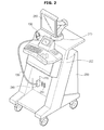
- FIG. 2 is a perspective view of a photoacoustic imaging apparatus having a built-in laser generator, according to an exemplary embodiment of the present invention.
- the photoacoustic imaging apparatus may include a main body 200, a photoacoustic probe, an input unit 250, a main display 260, and a sub display 270.
- the photoacoustic probe may include an ultrasonic probe 100.
- a controller for receiving photoacoustic signals collected by the ultrasonic probe 100 and converting the photoacoustic signals into photoacoustic images may be installed.
- a photoacoustic image has an advantage that it can show a functional image of tissues, based on a fact that tissues having different functional factors have different absorption rates with respect to a specific wavelength of laser although they have the same anatomical structure and accordingly cannot be distinguished by ultrasonic waves.
- One or more female connectors 245 are provided in one side of the main body 200.
- a male connector 240 connected to a cable 230 may be physically coupled with one of the female connectors 245.
- one or more optical fiber coupling terminals 220 with which one ends of optical fibers 120 (see FIG. 1 ) can be coupled may be provided.
- the optical fiber coupling terminals 220 may be connected to a laser generator installed inside or outside the photoacoustic imaging apparatus so that laser generated by the laser generator can be transferred to the photoacoustic probe along the optical fibers 120.
- the optical fibers 120 may be connected in series or in parallel to the laser generator through the optical fiber coupling terminals 220. That is, the photoacoustic probe may connect to the laser generator in an arbitrary manner.
- the input unit 250 allows a user to input commands for operating the photoacoustic imaging apparatus. For example, a user may input a command for starting photoacoustic diagnosis through the input unit 250, or may set a wavelength of light through the input unit 250. Commands input through the input unit 250 may be transmitted to the main body 200 through wired/wireless communication.
- the input unit 250 may include at least one of a keyboard, a foot switch, and a foot pedal.
- the keyboard may be hardwarily implemented and mounted on the upper part of the main body 200.
- the keyboard may include at least one of switches, keys, a joystick, and a trackball.
- the keyboard may be softwarily implemented like a Graphic User Interface (GUI).
- GUI Graphic User Interface
- the keyboard may be displayed on the screen of the main display 260 or the sub display270.
- the foot switch or the foot pedal may be provided in the lower part of the main body 200, and the user may control operations of the photoacoustic imaging apparatus using the foot pedal.
- the sub display 270 may be mounted on the main body 200. In the example of FIG. 2 , the sub display 270 is provided in the upper part of the input unit 250.
- the sub display 270 may display an application associated with operations of the photoacoustic imaging apparatus. For example, the sub display 270 may display a menu, guide information, and the like for photoacoustic diagnosis.
- the sub display 270 may be implemented as a Cathode Ray Tube (CRT), a Liquid Crystal Display (LCD), etc.
- the main display 260 may be provided in the main body 200.
- the main display 260 is positioned above the sub display 270.
- the main display 260 may display photoacoustic images acquired during photoacoustic diagnosis.
- the main display 260 may be, like the sub display 270, implemented as a CRT or a LCD.
- FIG. 2 shows a case in which the main display 260 is coupled with the main body 200, however, it is also possible that the main display 260 is detachably attached to the main body 200.
- the photoacoustic imaging apparatus includes both the main display 260 and the sub display 270.
- the sub display 270 may be omitted.
- the main display 260 may display applications, menus, etc., instead of the sub display 270.
- FIG. 3 is a top view of a photoacoustic probe in which an ultrasonic probe is combined with optical fibers.
- a ultrasonic probe 100 includes a piezoelectric module 102 to transmit and receive ultrasonic waves, an acoustic lens 101 disposed in front of the piezoelectric module 102 to focus ultrasonic waves, and optical fibers 120 to irradiate laser of a specific wavelength to a target.
- a laser generator for generating laser may be installed in a photoacoustic imaging apparatus, and a wavelength of laser that is to be generated by the laser generator may be appropriately selected in consideration of inside materials of a target.
- the photoacoustic imaging apparatus is an apparatus for imaging the inner tissue of a target using a photoacoustic effect, and since the photoacoustic imaging apparatus includes the ultrasonic probe 100 capable of transmitting and receiving ultrasonic waves, the photoacoustic imaging apparatus can also create a ultrasonic image of a target.
- the piezoelectric module 102 includes a piezoelectric layer for converting electrical signals into acoustic signals and vice versa, a matching layer disposed in front of the piezoelectric layer, and a backing layer disposed behind the piezoelectric layer.
- piezoelectric effect A phenomenon in which a voltage is generated when a mechanical pressure is applied to a specific material is called a piezoelectric effect, and a phenomenon in which mechanical deformation occurs when a voltage is applied to a specific material is called a converse piezoelectric effect.
- Materials having the piezoelectric effect and converse piezoelectric effect are piezoelectric materials. That is, piezoelectric materials are materials capable of converting electricity energy into mechanical vibration energy and vice versa.
- the piezoelectric layer which is made of a piezoelectric material, receives electrical signals, and converts the electrical signals into mechanical vibration to generate ultrasonic waves, and if receiving ultrasonic signals, the piezoelectric layer converts the ultrasonic signals into electrical signals.
- the piezoelectric material forming the piezoelectric layer may include ceramic of lead zirconate titanate (PZT), PMN-PT single crystals consisting of a solid solution of lead magnesium niobate (PMN) and lead titanate (PT), and PZN-PT single crystals consisting of a solid solution of lead zinc niobate (PZN) and lead titanate (PT).
- PZT lead zirconate titanate
- PMN-PT single crystals consisting of a solid solution of lead magnesium niobate (PMN) and lead titanate
- PT lead titanate
- the matching layer is disposed in front of the piezoelectric layer, and reduces a difference in acoustic impedance between the piezoelectric layer and a target so that ultrasonic waves generated by the piezoelectric layer can be effectively transferred to the target.
- the matching layer may be comprised of one or more layers, and may be divided into a plurality of units each having a predetermined width, together with the piezoelectric layer, by a dicing process.
- the backing layer is disposed behind the piezoelectric layer, and absorbs ultrasonic waves generated by the piezoelectric layer to block the ultrasonic waves from being transferred behind the piezoelectric layer, thereby preventing image distortion.
- the backing layer may be comprised of a plurality of layers in order to improve an attenuation/blocking effect with respect to ultrasonic waves.
- the acoustic lens 101 is disposed in front of the piezoelectric module 102, specifically, in front of the matching layer, to focus ultrasonic waves that are to be transmitted or received ultrasonic waves.
- the optical fibers 120 irradiate laser of a specific wavelength generated by the laser generator to a target. An alignment of the optical fibers 120 will be described later.
- the laser generator may generate single-wavelength laser or multi-wavelength laser. Also, the laser generator may generate pulsed laser or continuous laser. That is, the laser generator may generate various kinds or properties of laser. Accordingly, the laser generator may be a light-emitting device capable of generating a specific wavelength component or single-color light having such a specific wavelength component, such as a Laser Diode (LD), a Light-Emitting Diode (LED), a solid-state laser, and a gas laser.
- LD Laser Diode
- LED Light-Emitting Diode
- solid-state laser a gas laser.
- a Nd:YAG laser (a solid-state laser) capable of generating laser having a wavelength of about 1,000nm or a He-Ne gas laser capable of generating laser having a wavelength of 633nm is used to generate a laser beam having a pulse width of about 10nsec.
- a Nd:YAG laser a solid-state laser
- He-Ne gas laser capable of generating laser having a wavelength of 633nm is used to generate a laser beam having a pulse width of about 10nsec.
- hemoglobin absorbs light ranging from 600nm to 1,000nm although the hemoglobin has different optical absorption properties according to its type.
- An emission wavelength ranging from 550nm to 650nm can be generated using a small light-emitting device, such as a LD or a LED, made of InGaAlP
- a small light-emitting device such as a LD or a LED
- an emission wavelength ranging from 650nm to 900nm can be generated using a small light-emitting device (a LD or a LED) made of GaAlAs
- an emission wavelength ranging from 900nm to 2,300nm can be generated using a small light-emitting device (a LD or a LED) made of InGaAs or InGaAsP.
- an Optical Parametrical Oscillators (OPO) laser capable of changing a wavelength using nonlinear photonic crystals may be used.
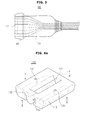
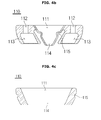
- FIGS. 4A , 4B, and 4C illustrate a photoacoustic bracket according to an exemplary embodiment of the present invention, wherein FIG. 4A is a perspective view of the photoacoustic bracket, FIG. 4B is a front sectional view of the photoacoustic bracket, and FIG. 4C is a side sectional view of the photoacoustic bracket.
- the front sectional view of the photoacoustic bracket is a sectional view appearing when the photoacoustic bracket illustrated in FIG. 4A is cut along a line A-A'
- the side sectional view of the photoacoustic bracket is a sectional view appearing when the photoacoustic bracket illustrated in FIG. 4A is cut along a line B-B'.
- the photoacoustic bracket has three grooves.
- a groove located in the center of the photoacoustic bracket is a probe coupling part 111 with which an ultrasonic probe 100 is coupled.
- the probe coupling part 111 may be formed in a specific shape corresponding to the ultrasonic probe 100 such that the ultrasonic probe 100 can be stably inserted in the probe coupling part 111.
- the external appearance of the photoacoustic bracket 110 may be formed in a specific shape such that the ultrasonic probe 100 can be stably fixed in the photoacoustic bracket 110 using a method such as interference fit or notch.
- Optical fiber coupling parts may be formed to be opposite to each other with the probe coupling part 111 in between.
- Each of the optical fiber coupling parts may include an optical fiber inserting hole 112 through which optical fibers are inserted and an inner space 113 in which one ends of the optical fibers are placed.
- the optical fiber inserting hole 112 When shown from the top, the optical fiber inserting hole 112 may be in the shape of a circle.
- the inner space 113 in which one ends of optical fibers are placed is formed with a wide area so that the optical fibers can be uniformly distributed over the wide area.
- the inner space 113 in which the ends of the optical fibers are placed helps laser output from the optical fibers arrive at a target without any interference.
- two optical fiber inserting holes 112 are provided, however, the number of optical fiber inserting holes is not limited so long as the photoacoustic bracket 110 includes one or more optical fiber inserting hole.
- a space may be formed below the acoustic lens 101 of the ultrasonic probe 100.
- the space is a space 114 in which a fluid-type light reflector 130 is to be placed.
- the depth of the space 114 decides the thickness of the light reflector 130 that is to beplaced.
- the light reflector 130 placed in the space 114 is fluid, and accordingly, the light reflector 130 may overflow or permeate through gaps of the photoacoustic bracket 110 to interfere with a transmission path of laser output from the optical fibers. Accordingly, in order to prevent the light reflector 130 from leaking into the inner spaces 113 in which the ends of the optical fibers are placed, a groove 115 for securely holding an inner cover may be formed.
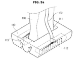
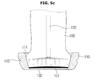
- FIGS. 5A , 5B , and 5C illustrate the photoacoustic probe according to an exemplary embodiment of the present invention when the optical fibers 120 and the ultrasonic probe 100 are coupled with the photoacoustic bracket 110, wherein FIG. 5A is a perspective view of the photoacoustic probe, FIG. 5B is a front sectional view of the photoacoustic probe, and FIG. 5C is a side sectional view of the photoacoustic probe.
- the ultrasonic probe 100 may be coupled with the probe coupling part 111 of the photoacoustic bracket 110. As described above, the ultrasonic probe 100 may be coupled with the photoacoustic bracket 110 using a method such as interference fit or notch.
- the ultrasonic probe 100 that is coupled with the photoacoustic bracket 110 may be a linear probe, a convex probe, or a phased array probe. That is, the kind of the ultrasonic probe 100 is not limited.
- the shape of the photoacoustic bracket 110 may depend on the kind of the ultrasonic probe 100 such that the ultrasonic probe 100 can be easily coupled with the photoacoustic bracket 110.
- Optical fibers may be inserted into optical fiber inserting holes 112.
- the optical fibers are provided as a plurality of bundles of optical fibers, and accordingly, the optical fibers may be uniformly distributed in the inner spaces 113 in which the ends of the optical fibers are placed.
- a fluid-type light reflector 130 may be placed in the space 114 formed below the acoustic lens 101 of the ultrasonic probe 100.
- the light reflector 130 reflects laser scattered from a target and then directed toward the acoustic lens 101 to redirect the laser toward the target, thereby minimizing generation of artifacts.
- the light reflector 130 may be a material having photoreflectance.
- the light reflector 130 may contain zinc oxide (ZnO) or titanium oxide (TiO) which is main ingredients of sunblock.
- ZnO zinc oxide
- TiO titanium oxide
- the light reflector 130 may be a material capable of minimizing or reducing scattering of ultrasonic waves while reflecting light.
- the light reflector 130 may be fluid.
- a solid-type light reflector requires a separate layer for impedance matching between the light reflector and an acoustic lens.
- a fluid-type light reflector requires no separate layer for impedance matching. The reason is because the light reflector itself acts as couplant for ultrasonic waves. Accordingly, photoacoustic ultrasonic waves can be generated without using any separate component in addition to attaching the ultrasonic probe 100 and the optical fibers 120 to the photoacoustic bracket 110.
- the light reflector 130 Since the light reflector 130 is fluid, as described above, the light reflector 130 may overflow to enter the inner spaces 113 in which the ends of the optical fibers are placed. Also, the light reflector 120 may permeate through gaps of the photoacoustic bracket 110 to interfere with the transmission path of laser irradiated from the optical fibers 120.
- the photoacoustic bracket 110 may include a groove 115 for holding an inner cover so as to prevent the light reflector 130 from leaking out.
- a method for holding an inner cover such that it is securely attached to the photoacoustic bracket 110 through the groove 115 will be described with reference to FIG. 6 , below.
- FIGS. 6A , 6B , and 6C illustrate the photoacoustic probe including the photoacoustic bracket 110 covered with an inner cover, according to an exemplary embodiment of the present invention, wherein FIG. 6A is a perspective view of the photoacoustic probe, FIG. 6B is a front sectional view of the photoacoustic probe, and FIG. 6C is a side sectional view of the photoacoustic probe.
- an inner cover 140 may be configured to surround the space 114 in which the light reflector 130 is placed in the photoacoustic bracket 110. As described above, the inner cover 140 is used to prevent the light reflector 130 from leaking into the inner spaces 113 in which the ends of optical fibers are placed.
- the inner cover 140 may include a circular loop for securely holding the inner cover 140 to the photoacoustic bracket 110.
- the circular loop is disposed along the groove 115 for holding the inner cover 140 so that the inner cover 140 is securely attached to the photoacoustic bracket 110 through the circular loop.
- the inner cover 140 may be made of a material that is the same as or similar to that of a cover for a conventional ultrasonic probe.
- the inner cover 140 may be made of polyurethane, latex, or polyethylene. Accordingly, the photoacoustic probe including the photoacoustic bracket 110 can perform diagnosis under the same conditions using the same method as the conventional ultrasonic probe.
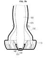
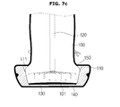
- FIGS. 7A , 7B , and 7C illustrate the photoacoustic probe including the photoacoustic bracket covered with an inner cover and an outer cover, according to an exemplary embodiment of the present invention, wherein FIG. 7A is a perspective view of the photoacoustic probe, FIG. 7B is a front sectional view of the photoacoustic probe, and FIG. 7C is a side sectional view of the photoacoustic probe.
- a need to disinfect a photoacoustic probe or to cover the photoacoustic probe with a probe cover is relatively low.
- a photoacoustic imaging apparatus is used in an operating room, there is a need to thoroughly manage and control the cleanliness of diagnostic equipment in order to avoid cross-contamination.
- a photoacoustic probe when used in an operating room, a photoacoustic probe should be thoroughly sterilized and disinfected before it enters the operating room, and also used after being entirely covered with a probe cover.
- an outer cover 150 to cover the photoacoustic probe is used.
- the outer cover 150 may wrap up the entire external surface of the photoacoustic probe, unlike the inner cover 140. Rubber bands may be used when wrapping up the photoacoustic probe with the outer cover 150 in order to securely hold the outer cover 150 on the photoacoustic probe while bringing it into close contact with the photoacoustic probe.
- the outer cover 150 may be, like the inner cover 140, made of a rubber material that is the same as or similar to that of a cover for a conventional ultrasonic probe.
- the outer cover 150 may be made of polyurethane, latex, or polyethylene.
- conventional couplant for ultrasonic waves may be used as couplant for photoacoustic waves for impedance matching. That is, the outer cover 150 made of the same material as the conventional cover for ultrasonic waves enables compatibility with other equipment (material) for ultrasonic diagnosis.
- the inner cover 140 and the outer cover 150 may constitute a single photoacoustic probe cover. That is, the inner cover 140 and the outer cover 150 may be produced as a single cover, or may be separately produced and then bonded later. When the inner cover 140 and the outer cover 150 are separately produced and then bonded, the inner cover 140 and the outer cover 150 may be bonded by Radio Frequency (RF) adhesion which is one of rubber adhesion processes. However, the inner cover 140 and the outer cover 150 may be bonded by any other rubber adhesion process.
- RF Radio Frequency
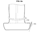
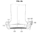
- FIGS. 8A and 8B illustrate a photoacoustic probe including a biopsy needle kit, according to an exemplary embodiment of the present invention, wherein FIG. 8A is a side view of the photoacoustic probe, and FIG. 8B is a side sectional view of the photoacoustic probe.
- a biopsy which is cytological examination is generally taken. If the tumor is seen with naked eyes or checked with hands from outside, a biopsy can be easily taken by inserting a biopsy needle into the tumor region without having to use ultrasonic waves. However, when the tumor is not seen with naked eyes or cannot be checked with hands from outside, a biopsy using an ultrasonic diagnosis apparatus is taken.
- a bracket enabling a biopsy needle kit to be coupled with an ultrasonic probe may be used.
- the bracket and the kit together guide the biopsy needle, thereby helping the biopsy needle be inserted into an exact lesion region, resulting in improvement of accuracy of biopsy.
- a biopsy needle kit coupler 160 for coupling with a biopsy needle kit 165 may be provided in one side of the photoacoustic bracket 110.
- the biopsy needle kit 165 is coupled with the biopsy kit coupler 160 of the photoacoustic bracket 110 to increase accuracy of diagnosis when photoacoustic diagonosis is performed together with a biopsy.
- the biopsy needle kit coupler 160 may be configured for the biopsy needle kit 165 to be coupled with the biopsy kit needle coupler 160 in the same coupling method in which a biopsy needle kit is coupled with a conventional bracket for an ultrasonic probe. Accordingly, the biopsy needle kit coupler 160 can be compatible with a biopsy needle kit for ultrasonic diagnosis. However, the biopsy needle kit coupler 160 may be coupled with a photoacoustic biopsy needle kit 165 in consideration of structural conditions.
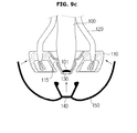
- FIGS. 9A , 9B , and 9C illustrate an order in which a conventional ultrasonic probe is used as the photoacoustic probe.
- FIG. 9A illustrates a step of inserting the ultrasonic probe 100 into the photoacoustic bracket 110.
- An ultrasonic probe 100 may be coupled with the probe coupling part 111 of the photoacoustic bracket 110.
- the ultrasonic probe 100 that is attached to the photoacoustic bracket 110 may be one of various kinds of conventional ultrasonic probes.
- the ultrasonic probe 100 may be coupled with the photoacoustic bracket 110 using a method such as interference fit or notch.
- the optical fibers 120 may be inserted into the optical fiber inserting holes 112 of the photoacoustic bracket 110.
- FIG. 9A shows a case in which two bundles of optical fibers 120 are respectively inserted in the optical fiber inserting holes 112, however, the number of optical fibers 120 that are inserted in the photoacoustic bracket 110 is not limited so long as one or more optical fibers 120 are inserted in the photoacoustic bracket 110.
- the optical fibers 120 may be uniformly distributed over wide areas in the inner spaces 113 in which ends of the optical fibers 120 are placed, so that laser can be irradiated to a wide region of a target.
- FIG. 9B illustrates a step of placing the fluid-type light reflector 130 into the photoacoustic bracket 110.
- the light reflector 130 may be placed into the space 114 formed below the acoustic lens 101 of the ultrasonic probe 100.
- the light reflector 130 again reflects the laser back toward the target to thus block the acoustic lens 101 from receiving the laser. Thereby, it is possible to reduce artifacts and increase accuracy of acoustic images.
- FIG. 9C illustrates a step of covering the photoacoustic probe with the inner cover 140 and the outer cover 150.
- the inner cover 140 may surround the space 114 in which the light reflector 130 is placed. Thereby, the inner cover 140 can prevent the light reflector 130 from interfering with a transmission path of laser irradiated from the optical fibers 120.
- the photoacoustic bracket 110 may include a groove 115 for securely holding the inner cover 140, and a circular loop of the inner cover 140 may be coupled with the groove 115 to securely hold the inner cover 140 to the photoacoustic bracket 110.
- the outer cover 150 may be used to wrap up the photoacoustic probe. By covering the photoacoustic probe with the outer cover 150 when the photoacoustic probe is used in an operating room with a higher risk of cross-contamination than in a general diagnosis room, the risk of cross-contamination can be minimized. Also, rubber bands to securely hold the outer cover 150 may be used.
- the inner cover 140 and the outer cover 150 may be made of the same rubber material as a cover for a conventional ultrasonic probe.
- the inner cover 140 and the outer cover 150 made of a rubber material enable compatibility with other equipment (material) for ultrasonic diagnosis.
- conventional couplant for ultrasonic waves may be used as couplant for the photoacoustic probe for impedance matching.
- the inner cover 140 and the outer cover 150 may constitute a single photoacoustic probe cover.
- the inner cover 140 and the outer cover 150 may be separately produced and then bonded later using a rubber adhesion process, for example, RF adhesion.
- the photoacoustic probe may be used for medical purposes, for example, diagnosis, treatment, operation, etc., targeting biologic tissues.
- the photoacoustic probe may be used in all behaviors targeting biologic tissues other than medical purposes.
- the photoacoustic probe may be used to examine non-biologic tissues when their photoacoustic images are needed.
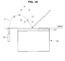
- FIG. 10 is a view for describing an effect of the photoacoustic probe including the light reflector 130, according to an exemplary embodiment of the present invention.
- a photoacoustic probe having no light reflector irradiates laser to a target
- a part of the irradiated laser is scattered by light scatterers 3 in the target.
- the scattered laser may be absorbed by the acoustic lens 101, and the acoustic lens 101 generates acoustic waves by absorbing the laser.
- the acoustic waves are again radiated, thereby making artifacts.
- the light reflector again reflects the scattered laser toward the target. Accordingly, the acoustic lens 101 generates no acoustic waves, which are generated when the acoustic lens 101 absorbs the scattered laser, resulting in reduction of artifacts.
Landscapes
- Health & Medical Sciences (AREA)
- Life Sciences & Earth Sciences (AREA)
- Physics & Mathematics (AREA)
- General Health & Medical Sciences (AREA)
- Pathology (AREA)
- Surgery (AREA)
- Biomedical Technology (AREA)
- Engineering & Computer Science (AREA)
- Veterinary Medicine (AREA)
- Heart & Thoracic Surgery (AREA)
- Medical Informatics (AREA)
- Molecular Biology (AREA)
- Animal Behavior & Ethology (AREA)
- Public Health (AREA)
- Biophysics (AREA)
- Nuclear Medicine, Radiotherapy & Molecular Imaging (AREA)
- Radiology & Medical Imaging (AREA)
- Acoustics & Sound (AREA)
- Chemical & Material Sciences (AREA)
- Analytical Chemistry (AREA)
- Biochemistry (AREA)
- General Physics & Mathematics (AREA)
- Immunology (AREA)
- Optics & Photonics (AREA)
- Ultra Sonic Daignosis Equipment (AREA)
- Investigating Or Analyzing Materials By The Use Of Ultrasonic Waves (AREA)
Applications Claiming Priority (1)
| Application Number | Priority Date | Filing Date | Title |
|---|---|---|---|
| KR1020130056659A KR102149322B1 (ko) | 2013-05-20 | 2013-05-20 | 광음향 프로브 어셈블리 및 이를 포함하는 광음향 영상 장치 |
Publications (3)
| Publication Number | Publication Date |
|---|---|
| EP2805672A2 true EP2805672A2 (fr) | 2014-11-26 |
| EP2805672A3 EP2805672A3 (fr) | 2015-04-08 |
| EP2805672B1 EP2805672B1 (fr) | 2017-08-30 |
Family
ID=50272318
Family Applications (1)
| Application Number | Title | Priority Date | Filing Date |
|---|---|---|---|
| EP14158077.9A Not-in-force EP2805672B1 (fr) | 2013-05-20 | 2014-03-06 | Support photo-acoustique, sonde photo-acoustique et appareil d'imagerie photo-acoustique en disposant |
Country Status (3)
| Country | Link |
|---|---|
| US (1) | US9702854B2 (fr) |
| EP (1) | EP2805672B1 (fr) |
| KR (1) | KR102149322B1 (fr) |
Cited By (5)
| Publication number | Priority date | Publication date | Assignee | Title |
|---|---|---|---|---|
| EP3243443A4 (fr) * | 2015-01-08 | 2018-08-15 | FUJIFILM Corporation | Sonde pour mesure photo-acoustique, unité de sonde la comprenant et dispositif de mesure photo-acoustique |
| CN109310395A (zh) * | 2016-06-20 | 2019-02-05 | 蝴蝶网络有限公司 | 通用超声装置以及相关设备和方法 |
| EP3646775A1 (fr) * | 2018-10-29 | 2020-05-06 | iThera Medical GmbH | Sonde et système d'imagerie opto-acoustique et procédé pour commander une telle sonde |
| US11344204B2 (en) | 2015-01-08 | 2022-05-31 | Fujifilm Corporation | Photoacoustic measurement probe and probe unit and photoacoustic measurement apparatus including the same |
| US11540805B2 (en) | 2016-06-20 | 2023-01-03 | Bfly Operations, Inc. | Universal ultrasound device and related apparatus and methods |
Families Citing this family (11)
| Publication number | Priority date | Publication date | Assignee | Title |
|---|---|---|---|---|
| JP6152079B2 (ja) * | 2014-08-29 | 2017-06-21 | プレキシオン株式会社 | 光音響画像化装置用プローブ |
| RU2603819C2 (ru) * | 2015-03-30 | 2016-11-27 | Федеральное государственное бюджетное образовательное учреждение высшего образования "Саратовский национальный исследовательский государственный университет имени Н.Г. Чернышевского" | Оптоакустический объектив |
| US11083437B2 (en) * | 2015-11-02 | 2021-08-10 | Purdue Research Foundation | Method and device for in situ cancer margin detection |
| KR101936120B1 (ko) | 2016-11-30 | 2019-01-08 | 부경대학교 산학협력단 | 광음향 단층촬영을 위한 프로브 및 실시간 광음향 단층촬영 장치 |
| US20190076123A1 (en) * | 2017-09-12 | 2019-03-14 | Colgate-Palmolive Company | Imaging System and Method Therefor |
| CN108888236A (zh) * | 2018-04-23 | 2018-11-27 | 深圳迈瑞生物医疗电子股份有限公司 | 一种多模态成像系统及方法 |
| CN108938079A (zh) * | 2018-08-16 | 2018-12-07 | 深圳先进技术研究院 | 一种探针及探针定位系统 |
| JP7221809B2 (ja) * | 2019-06-13 | 2023-02-14 | 富士フイルム株式会社 | アタッチメント及び超音波プローブ |
| CN112716529A (zh) * | 2019-10-28 | 2021-04-30 | 深圳市理邦精密仪器股份有限公司 | 眼球检测设备及其超声探头 |
| KR102511753B1 (ko) | 2020-11-19 | 2023-03-20 | 지앨에스 주식회사 | 의료용 진단장치 |
| WO2022141108A1 (fr) * | 2020-12-29 | 2022-07-07 | 深圳迈瑞生物医疗电子股份有限公司 | Sonde d'imagerie photoacoustique et système d'imagerie photoacoustique |
Family Cites Families (20)
| Publication number | Priority date | Publication date | Assignee | Title |
|---|---|---|---|---|
| NL7707065A (nl) * | 1976-06-28 | 1977-12-30 | Bicron Corp | Scintillatiedetector. |
| EP0131654A1 (fr) * | 1983-07-19 | 1985-01-23 | N.V. Optische Industrie "De Oude Delft" | Dispositif pour la destruction à distance des objets pierreux présents dans le corps par ondes de choc soniques |
| JP2002528202A (ja) * | 1998-10-23 | 2002-09-03 | コーニンクレッカ フィリップス エレクトロニクス エヌ ヴィ | 合成樹脂パネルが設けられた合成樹脂壁部を備えるハウジングを有する装置 |
| JP4820239B2 (ja) * | 2006-08-28 | 2011-11-24 | 公立大学法人大阪府立大学 | 光トモグラフィ装置用プローブ |
| US20090158821A1 (en) * | 2007-12-20 | 2009-06-25 | General Electric Company | Devices, methods and systems for measuring one or more characteristics of a suspension |
| JP2009240658A (ja) * | 2008-03-31 | 2009-10-22 | Fujinon Corp | 超音波プローブ用バルーン及び超音波内視鏡 |
| JP2010005194A (ja) * | 2008-06-27 | 2010-01-14 | Fujifilm Corp | レーザ治療装置 |
| JP4900979B2 (ja) * | 2008-08-27 | 2012-03-21 | キヤノン株式会社 | 光音響装置および光音響波を受信するための探触子 |
| US20100094134A1 (en) * | 2008-10-14 | 2010-04-15 | The University Of Connecticut | Method and apparatus for medical imaging using near-infrared optical tomography combined with photoacoustic and ultrasound guidance |
| US8068229B2 (en) * | 2009-04-30 | 2011-11-29 | Alcatel Lucent | Optofluidic devices |
| JP5709368B2 (ja) * | 2009-11-04 | 2015-04-30 | キヤノン株式会社 | 生体情報取得装置 |
| EP2501320A4 (fr) * | 2009-11-19 | 2014-03-26 | Univ Johns Hopkins | Systèmes de navigation et d'intervention guidés par image à faible coût utilisant des ensembles coopératifs de capteurs locaux |
| JP5743715B2 (ja) * | 2011-05-26 | 2015-07-01 | キヤノン株式会社 | 音響信号受信装置 |
| JP2012249739A (ja) * | 2011-06-01 | 2012-12-20 | Fujifilm Corp | 光音響撮像装置およびその作動方法 |
| JP5743957B2 (ja) * | 2011-06-07 | 2015-07-01 | 富士フイルム株式会社 | 光音響画像生成装置及び方法 |
| EP2548516A1 (fr) * | 2011-07-20 | 2013-01-23 | Universiteit Twente | Système pour faciliter la génération d'images photoacoustiques |
| JP2013056100A (ja) * | 2011-09-09 | 2013-03-28 | Canon Inc | 光音響整合材 |
| EP2763591A4 (fr) * | 2011-10-09 | 2015-05-06 | Clear Guide Medical Llc | Guidage d'images in situ interventionnelles par fusion d'une vidéo ultrasonore |
| JP5860822B2 (ja) * | 2012-02-13 | 2016-02-16 | 富士フイルム株式会社 | 音響波検出用のプローブおよびそれを備えた光音響計測装置 |
| US20140073899A1 (en) * | 2012-09-12 | 2014-03-13 | Nellcor Puritan Bennett LLC. | Photoacoustic sensor system |
-
2013
- 2013-05-20 KR KR1020130056659A patent/KR102149322B1/ko active IP Right Grant
-
2014
- 2014-03-06 EP EP14158077.9A patent/EP2805672B1/fr not_active Not-in-force
- 2014-05-15 US US14/279,108 patent/US9702854B2/en active Active
Non-Patent Citations (1)
| Title |
|---|
| None |
Cited By (7)
| Publication number | Priority date | Publication date | Assignee | Title |
|---|---|---|---|---|
| EP3243443A4 (fr) * | 2015-01-08 | 2018-08-15 | FUJIFILM Corporation | Sonde pour mesure photo-acoustique, unité de sonde la comprenant et dispositif de mesure photo-acoustique |
| US11344204B2 (en) | 2015-01-08 | 2022-05-31 | Fujifilm Corporation | Photoacoustic measurement probe and probe unit and photoacoustic measurement apparatus including the same |
| CN109310395A (zh) * | 2016-06-20 | 2019-02-05 | 蝴蝶网络有限公司 | 通用超声装置以及相关设备和方法 |
| US11446001B2 (en) | 2016-06-20 | 2022-09-20 | Bfly Operations, Inc. | Universal ultrasound device and related apparatus and methods |
| US11540805B2 (en) | 2016-06-20 | 2023-01-03 | Bfly Operations, Inc. | Universal ultrasound device and related apparatus and methods |
| US11712221B2 (en) | 2016-06-20 | 2023-08-01 | Bfly Operations, Inc. | Universal ultrasound device and related apparatus and methods |
| EP3646775A1 (fr) * | 2018-10-29 | 2020-05-06 | iThera Medical GmbH | Sonde et système d'imagerie opto-acoustique et procédé pour commander une telle sonde |
Also Published As
| Publication number | Publication date |
|---|---|
| KR102149322B1 (ko) | 2020-08-28 |
| EP2805672B1 (fr) | 2017-08-30 |
| US20140340685A1 (en) | 2014-11-20 |
| US9702854B2 (en) | 2017-07-11 |
| KR20140136305A (ko) | 2014-11-28 |
| EP2805672A3 (fr) | 2015-04-08 |
Similar Documents
| Publication | Publication Date | Title |
|---|---|---|
| US9702854B2 (en) | Photoacousticbracket, photoacoustic probe and photoacoustic imaging apparatus having the same | |
| CN100353910C (zh) | 非探入式受检体信息成象装置 | |
| US6979292B2 (en) | Method and apparatus for forming an image that shows information about a subject | |
| US10709419B2 (en) | Dual modality imaging system for coregistered functional and anatomical mapping | |
| JP4820239B2 (ja) | 光トモグラフィ装置用プローブ | |
| US10433732B2 (en) | Optoacoustic imaging system having handheld probe utilizing optically reflective material | |
| US20130301380A1 (en) | Method for dual modality optoacoustic imaging | |
| JP2016013479A (ja) | 対象体の断層光音響撮像用の手持ち式装置及び方法 | |
| AU2012332233A1 (en) | Dual modality imaging system for coregistered functional and anatomical mapping | |
| KR101994937B1 (ko) | 어레이 트랜듀서 기반 측면 스캔 광음향-초음파 내시경 시스템 | |
| JP5702313B2 (ja) | 光音響分析用プローブユニットおよび光音響分析装置 | |
| US20080097217A1 (en) | Ultrasound, Probe, Ultraonograph, And Ultrasonigraphy | |
| US10499887B2 (en) | Biopsy needle and photoacoustic measurement apparatus | |
| US10849507B2 (en) | Photoacoustic image generation apparatus and insert | |
| US20190150749A1 (en) | Optoacoustic probe | |
| US20220133273A1 (en) | Transparent ultrasound transducers for photoacoustic imaging | |
| JP2016144523A (ja) | 手持ち式プローブ | |
| KR20130081067A (ko) | 초음파 진단 장치 및 방법 | |
| US10722263B2 (en) | Biopsy needle and photoacoustic measurement apparatus | |
| JPWO2018061806A1 (ja) | 挿入物およびその挿入物を備えた光音響計測装置並びに挿入物の製造方法 | |
| CN115553817A (zh) | 血管内成像导管及血管内成像系统 | |
| KR20240070598A (ko) | 전립선 영상화를 위한 광음향 프로브 | |
| JP2014138883A (ja) | 生体検査装置 | |
| EP2773267B1 (fr) | Système d'imagerie bimodal pour cartographie fonctionnelle et cartographie anatomique co-enregistrées | |
| Guo | Integrated Active Ultrasound Systems for Medical Interventions |
Legal Events
| Date | Code | Title | Description |
|---|---|---|---|
| PUAI | Public reference made under article 153(3) epc to a published international application that has entered the european phase |
Free format text: ORIGINAL CODE: 0009012 |
|
| 17P | Request for examination filed |
Effective date: 20140306 |
|
| AK | Designated contracting states |
Kind code of ref document: A2 Designated state(s): AL AT BE BG CH CY CZ DE DK EE ES FI FR GB GR HR HU IE IS IT LI LT LU LV MC MK MT NL NO PL PT RO RS SE SI SK SM TR |
|
| AX | Request for extension of the european patent |
Extension state: BA ME |
|
| PUAL | Search report despatched |
Free format text: ORIGINAL CODE: 0009013 |
|
| AK | Designated contracting states |
Kind code of ref document: A3 Designated state(s): AL AT BE BG CH CY CZ DE DK EE ES FI FR GB GR HR HU IE IS IT LI LT LU LV MC MK MT NL NO PL PT RO RS SE SI SK SM TR |
|
| AX | Request for extension of the european patent |
Extension state: BA ME |
|
| RIC1 | Information provided on ipc code assigned before grant |
Ipc: A61B 17/34 20060101ALI20150302BHEP Ipc: A61B 8/00 20060101ALN20150302BHEP Ipc: A61B 5/00 20060101AFI20150302BHEP Ipc: G01N 29/24 20060101ALI20150302BHEP Ipc: G01N 21/17 20060101ALI20150302BHEP |
|
| R17P | Request for examination filed (corrected) |
Effective date: 20151008 |
|
| RBV | Designated contracting states (corrected) |
Designated state(s): AL AT BE BG CH CY CZ DE DK EE ES FI FR GB GR HR HU IE IS IT LI LT LU LV MC MK MT NL NO PL PT RO RS SE SI SK SM TR |
|
| 17Q | First examination report despatched |
Effective date: 20160622 |
|
| GRAP | Despatch of communication of intention to grant a patent |
Free format text: ORIGINAL CODE: EPIDOSNIGR1 |
|
| RIC1 | Information provided on ipc code assigned before grant |
Ipc: A61B 5/00 20060101AFI20170210BHEP Ipc: A61B 8/00 20060101ALN20170210BHEP Ipc: A61B 10/02 20060101ALI20170210BHEP Ipc: G01N 21/17 20060101ALI20170210BHEP Ipc: A61B 17/34 20060101ALI20170210BHEP Ipc: G01N 29/24 20060101ALI20170210BHEP |
|
| INTG | Intention to grant announced |
Effective date: 20170316 |
|
| GRAS | Grant fee paid |
Free format text: ORIGINAL CODE: EPIDOSNIGR3 |
|
| GRAA | (expected) grant |
Free format text: ORIGINAL CODE: 0009210 |
|
| AK | Designated contracting states |
Kind code of ref document: B1 Designated state(s): AL AT BE BG CH CY CZ DE DK EE ES FI FR GB GR HR HU IE IS IT LI LT LU LV MC MK MT NL NO PL PT RO RS SE SI SK SM TR |
|
| REG | Reference to a national code |
Ref country code: GB Ref legal event code: FG4D |
|
| REG | Reference to a national code |
Ref country code: CH Ref legal event code: EP |
|
| REG | Reference to a national code |
Ref country code: AT Ref legal event code: REF Ref document number: 922734 Country of ref document: AT Kind code of ref document: T Effective date: 20170915 |
|
| REG | Reference to a national code |
Ref country code: IE Ref legal event code: FG4D |
|
| REG | Reference to a national code |
Ref country code: DE Ref legal event code: R096 Ref document number: 602014013691 Country of ref document: DE |
|
| REG | Reference to a national code |
Ref country code: NL Ref legal event code: FP |
|
| REG | Reference to a national code |
Ref country code: LT Ref legal event code: MG4D |
|
| REG | Reference to a national code |
Ref country code: AT Ref legal event code: MK05 Ref document number: 922734 Country of ref document: AT Kind code of ref document: T Effective date: 20170830 |
|
| PG25 | Lapsed in a contracting state [announced via postgrant information from national office to epo] |
Ref country code: SE Free format text: LAPSE BECAUSE OF FAILURE TO SUBMIT A TRANSLATION OF THE DESCRIPTION OR TO PAY THE FEE WITHIN THE PRESCRIBED TIME-LIMIT Effective date: 20170830 Ref country code: HR Free format text: LAPSE BECAUSE OF FAILURE TO SUBMIT A TRANSLATION OF THE DESCRIPTION OR TO PAY THE FEE WITHIN THE PRESCRIBED TIME-LIMIT Effective date: 20170830 Ref country code: FI Free format text: LAPSE BECAUSE OF FAILURE TO SUBMIT A TRANSLATION OF THE DESCRIPTION OR TO PAY THE FEE WITHIN THE PRESCRIBED TIME-LIMIT Effective date: 20170830 Ref country code: NO Free format text: LAPSE BECAUSE OF FAILURE TO SUBMIT A TRANSLATION OF THE DESCRIPTION OR TO PAY THE FEE WITHIN THE PRESCRIBED TIME-LIMIT Effective date: 20171130 Ref country code: LT Free format text: LAPSE BECAUSE OF FAILURE TO SUBMIT A TRANSLATION OF THE DESCRIPTION OR TO PAY THE FEE WITHIN THE PRESCRIBED TIME-LIMIT Effective date: 20170830 Ref country code: AT Free format text: LAPSE BECAUSE OF FAILURE TO SUBMIT A TRANSLATION OF THE DESCRIPTION OR TO PAY THE FEE WITHIN THE PRESCRIBED TIME-LIMIT Effective date: 20170830 |
|
| REG | Reference to a national code |
Ref country code: FR Ref legal event code: PLFP Year of fee payment: 5 |
|
| PG25 | Lapsed in a contracting state [announced via postgrant information from national office to epo] |
Ref country code: GR Free format text: LAPSE BECAUSE OF FAILURE TO SUBMIT A TRANSLATION OF THE DESCRIPTION OR TO PAY THE FEE WITHIN THE PRESCRIBED TIME-LIMIT Effective date: 20171201 Ref country code: IS Free format text: LAPSE BECAUSE OF FAILURE TO SUBMIT A TRANSLATION OF THE DESCRIPTION OR TO PAY THE FEE WITHIN THE PRESCRIBED TIME-LIMIT Effective date: 20171230 Ref country code: BG Free format text: LAPSE BECAUSE OF FAILURE TO SUBMIT A TRANSLATION OF THE DESCRIPTION OR TO PAY THE FEE WITHIN THE PRESCRIBED TIME-LIMIT Effective date: 20171130 Ref country code: ES Free format text: LAPSE BECAUSE OF FAILURE TO SUBMIT A TRANSLATION OF THE DESCRIPTION OR TO PAY THE FEE WITHIN THE PRESCRIBED TIME-LIMIT Effective date: 20170830 Ref country code: RS Free format text: LAPSE BECAUSE OF FAILURE TO SUBMIT A TRANSLATION OF THE DESCRIPTION OR TO PAY THE FEE WITHIN THE PRESCRIBED TIME-LIMIT Effective date: 20170830 Ref country code: LV Free format text: LAPSE BECAUSE OF FAILURE TO SUBMIT A TRANSLATION OF THE DESCRIPTION OR TO PAY THE FEE WITHIN THE PRESCRIBED TIME-LIMIT Effective date: 20170830 |
|
| PG25 | Lapsed in a contracting state [announced via postgrant information from national office to epo] |
Ref country code: CZ Free format text: LAPSE BECAUSE OF FAILURE TO SUBMIT A TRANSLATION OF THE DESCRIPTION OR TO PAY THE FEE WITHIN THE PRESCRIBED TIME-LIMIT Effective date: 20170830 Ref country code: DK Free format text: LAPSE BECAUSE OF FAILURE TO SUBMIT A TRANSLATION OF THE DESCRIPTION OR TO PAY THE FEE WITHIN THE PRESCRIBED TIME-LIMIT Effective date: 20170830 Ref country code: RO Free format text: LAPSE BECAUSE OF FAILURE TO SUBMIT A TRANSLATION OF THE DESCRIPTION OR TO PAY THE FEE WITHIN THE PRESCRIBED TIME-LIMIT Effective date: 20170830 Ref country code: PL Free format text: LAPSE BECAUSE OF FAILURE TO SUBMIT A TRANSLATION OF THE DESCRIPTION OR TO PAY THE FEE WITHIN THE PRESCRIBED TIME-LIMIT Effective date: 20170830 |
|
| PG25 | Lapsed in a contracting state [announced via postgrant information from national office to epo] |
Ref country code: SM Free format text: LAPSE BECAUSE OF FAILURE TO SUBMIT A TRANSLATION OF THE DESCRIPTION OR TO PAY THE FEE WITHIN THE PRESCRIBED TIME-LIMIT Effective date: 20170830 Ref country code: EE Free format text: LAPSE BECAUSE OF FAILURE TO SUBMIT A TRANSLATION OF THE DESCRIPTION OR TO PAY THE FEE WITHIN THE PRESCRIBED TIME-LIMIT Effective date: 20170830 Ref country code: SK Free format text: LAPSE BECAUSE OF FAILURE TO SUBMIT A TRANSLATION OF THE DESCRIPTION OR TO PAY THE FEE WITHIN THE PRESCRIBED TIME-LIMIT Effective date: 20170830 |
|
| REG | Reference to a national code |
Ref country code: DE Ref legal event code: R097 Ref document number: 602014013691 Country of ref document: DE |
|
| PLBE | No opposition filed within time limit |
Free format text: ORIGINAL CODE: 0009261 |
|
| STAA | Information on the status of an ep patent application or granted ep patent |
Free format text: STATUS: NO OPPOSITION FILED WITHIN TIME LIMIT |
|
| 26N | No opposition filed |
Effective date: 20180531 |
|
| PG25 | Lapsed in a contracting state [announced via postgrant information from national office to epo] |
Ref country code: SI Free format text: LAPSE BECAUSE OF FAILURE TO SUBMIT A TRANSLATION OF THE DESCRIPTION OR TO PAY THE FEE WITHIN THE PRESCRIBED TIME-LIMIT Effective date: 20170830 |
|
| REG | Reference to a national code |
Ref country code: CH Ref legal event code: PL |
|
| GBPC | Gb: european patent ceased through non-payment of renewal fee |
Effective date: 20180306 |
|
| PG25 | Lapsed in a contracting state [announced via postgrant information from national office to epo] |
Ref country code: MC Free format text: LAPSE BECAUSE OF FAILURE TO SUBMIT A TRANSLATION OF THE DESCRIPTION OR TO PAY THE FEE WITHIN THE PRESCRIBED TIME-LIMIT Effective date: 20170830 |
|
| REG | Reference to a national code |
Ref country code: BE Ref legal event code: MM Effective date: 20180331 |
|
| REG | Reference to a national code |
Ref country code: IE Ref legal event code: MM4A |
|
| PG25 | Lapsed in a contracting state [announced via postgrant information from national office to epo] |
Ref country code: LU Free format text: LAPSE BECAUSE OF NON-PAYMENT OF DUE FEES Effective date: 20180306 |
|
| PG25 | Lapsed in a contracting state [announced via postgrant information from national office to epo] |
Ref country code: IE Free format text: LAPSE BECAUSE OF NON-PAYMENT OF DUE FEES Effective date: 20180306 |
|
| PG25 | Lapsed in a contracting state [announced via postgrant information from national office to epo] |
Ref country code: GB Free format text: LAPSE BECAUSE OF NON-PAYMENT OF DUE FEES Effective date: 20180306 Ref country code: CH Free format text: LAPSE BECAUSE OF NON-PAYMENT OF DUE FEES Effective date: 20180331 Ref country code: LI Free format text: LAPSE BECAUSE OF NON-PAYMENT OF DUE FEES Effective date: 20180331 Ref country code: BE Free format text: LAPSE BECAUSE OF NON-PAYMENT OF DUE FEES Effective date: 20180331 |
|
| PG25 | Lapsed in a contracting state [announced via postgrant information from national office to epo] |
Ref country code: MT Free format text: LAPSE BECAUSE OF NON-PAYMENT OF DUE FEES Effective date: 20180306 |
|
| PG25 | Lapsed in a contracting state [announced via postgrant information from national office to epo] |
Ref country code: TR Free format text: LAPSE BECAUSE OF FAILURE TO SUBMIT A TRANSLATION OF THE DESCRIPTION OR TO PAY THE FEE WITHIN THE PRESCRIBED TIME-LIMIT Effective date: 20170830 |
|
| PGFP | Annual fee paid to national office [announced via postgrant information from national office to epo] |
Ref country code: NL Payment date: 20200206 Year of fee payment: 7 |
|
| PG25 | Lapsed in a contracting state [announced via postgrant information from national office to epo] |
Ref country code: HU Free format text: LAPSE BECAUSE OF FAILURE TO SUBMIT A TRANSLATION OF THE DESCRIPTION OR TO PAY THE FEE WITHIN THE PRESCRIBED TIME-LIMIT; INVALID AB INITIO Effective date: 20140306 Ref country code: PT Free format text: LAPSE BECAUSE OF FAILURE TO SUBMIT A TRANSLATION OF THE DESCRIPTION OR TO PAY THE FEE WITHIN THE PRESCRIBED TIME-LIMIT Effective date: 20170830 |
|
| PG25 | Lapsed in a contracting state [announced via postgrant information from national office to epo] |
Ref country code: CY Free format text: LAPSE BECAUSE OF FAILURE TO SUBMIT A TRANSLATION OF THE DESCRIPTION OR TO PAY THE FEE WITHIN THE PRESCRIBED TIME-LIMIT Effective date: 20170830 Ref country code: MK Free format text: LAPSE BECAUSE OF NON-PAYMENT OF DUE FEES Effective date: 20170830 |
|
| PG25 | Lapsed in a contracting state [announced via postgrant information from national office to epo] |
Ref country code: AL Free format text: LAPSE BECAUSE OF FAILURE TO SUBMIT A TRANSLATION OF THE DESCRIPTION OR TO PAY THE FEE WITHIN THE PRESCRIBED TIME-LIMIT Effective date: 20170830 |
|
| PGFP | Annual fee paid to national office [announced via postgrant information from national office to epo] |
Ref country code: IT Payment date: 20210311 Year of fee payment: 8 Ref country code: FR Payment date: 20210216 Year of fee payment: 8 |
|
| PGFP | Annual fee paid to national office [announced via postgrant information from national office to epo] |
Ref country code: DE Payment date: 20210208 Year of fee payment: 8 |
|
| REG | Reference to a national code |
Ref country code: NL Ref legal event code: MM Effective date: 20210401 |
|
| PG25 | Lapsed in a contracting state [announced via postgrant information from national office to epo] |
Ref country code: NL Free format text: LAPSE BECAUSE OF NON-PAYMENT OF DUE FEES Effective date: 20210401 |
|
| REG | Reference to a national code |
Ref country code: DE Ref legal event code: R119 Ref document number: 602014013691 Country of ref document: DE |
|
| PG25 | Lapsed in a contracting state [announced via postgrant information from national office to epo] |
Ref country code: FR Free format text: LAPSE BECAUSE OF NON-PAYMENT OF DUE FEES Effective date: 20220331 Ref country code: DE Free format text: LAPSE BECAUSE OF NON-PAYMENT OF DUE FEES Effective date: 20221001 |
|
| PG25 | Lapsed in a contracting state [announced via postgrant information from national office to epo] |
Ref country code: IT Free format text: LAPSE BECAUSE OF NON-PAYMENT OF DUE FEES Effective date: 20220306 |